EP3819075A1 - Machining tool - Google Patents
Machining tool Download PDFInfo
- Publication number
- EP3819075A1 EP3819075A1 EP19831371.0A EP19831371A EP3819075A1 EP 3819075 A1 EP3819075 A1 EP 3819075A1 EP 19831371 A EP19831371 A EP 19831371A EP 3819075 A1 EP3819075 A1 EP 3819075A1
- Authority
- EP
- European Patent Office
- Prior art keywords
- steel ball
- spring
- clamp cover
- axial direction
- cylindrical part
- Prior art date
- Legal status (The legal status is an assumption and is not a legal conclusion. Google has not performed a legal analysis and makes no representation as to the accuracy of the status listed.)
- Granted
Links
Images



Classifications
-
- B—PERFORMING OPERATIONS; TRANSPORTING
- B23—MACHINE TOOLS; METAL-WORKING NOT OTHERWISE PROVIDED FOR
- B23B—TURNING; BORING
- B23B31/00—Chucks; Expansion mandrels; Adaptations thereof for remote control
- B23B31/02—Chucks
- B23B31/08—Chucks holding tools yieldably
- B23B31/083—Chucks holding tools yieldably axially
-
- B—PERFORMING OPERATIONS; TRANSPORTING
- B23—MACHINE TOOLS; METAL-WORKING NOT OTHERWISE PROVIDED FOR
- B23B—TURNING; BORING
- B23B31/00—Chucks; Expansion mandrels; Adaptations thereof for remote control
- B23B31/02—Chucks
-
- B—PERFORMING OPERATIONS; TRANSPORTING
- B23—MACHINE TOOLS; METAL-WORKING NOT OTHERWISE PROVIDED FOR
- B23B—TURNING; BORING
- B23B31/00—Chucks; Expansion mandrels; Adaptations thereof for remote control
- B23B31/02—Chucks
- B23B31/10—Chucks characterised by the retaining or gripping devices or their immediate operating means
- B23B31/107—Retention by laterally-acting detents, e.g. pins, screws, wedges; Retention by loose elements, e.g. balls
- B23B31/1071—Retention by balls
-
- B—PERFORMING OPERATIONS; TRANSPORTING
- B23—MACHINE TOOLS; METAL-WORKING NOT OTHERWISE PROVIDED FOR
- B23B—TURNING; BORING
- B23B2231/00—Details of chucks, toolholder shanks or tool shanks
- B23B2231/54—Chucks for taps
-
- B—PERFORMING OPERATIONS; TRANSPORTING
- B23—MACHINE TOOLS; METAL-WORKING NOT OTHERWISE PROVIDED FOR
- B23B—TURNING; BORING
- B23B2250/00—Compensating adverse effects during turning, boring or drilling
- B23B2250/12—Cooling and lubrication
-
- B—PERFORMING OPERATIONS; TRANSPORTING
- B23—MACHINE TOOLS; METAL-WORKING NOT OTHERWISE PROVIDED FOR
- B23B—TURNING; BORING
- B23B2260/00—Details of constructional elements
- B23B2260/136—Springs
-
- B—PERFORMING OPERATIONS; TRANSPORTING
- B23—MACHINE TOOLS; METAL-WORKING NOT OTHERWISE PROVIDED FOR
- B23B—TURNING; BORING
- B23B31/00—Chucks; Expansion mandrels; Adaptations thereof for remote control
- B23B31/02—Chucks
- B23B31/10—Chucks characterised by the retaining or gripping devices or their immediate operating means
- B23B31/12—Chucks with simultaneously-acting jaws, whether or not also individually adjustable
- B23B31/20—Longitudinally-split sleeves, e.g. collet chucks
Definitions
- the present invention relates to a machining tool, and more particularly to a machining tool capable of performing minute expansion and contraction in an axial direction.
- Patent Document 1 Japanese Unexamined Patent Application Publication No. 2012-11474 shows a machining tool (tapper) that is capable of performing minute expansion and contraction in an axial direction.
- the structure of this machining tool is shown in FIG. 8 .
- This machining tool consists of an upper body 1 and a holder body 2.
- the upper part of upper body 1 is configured to be attached to a machine tool spindle, and the lower end of holder body 2 is configured such that a tool (tap) is attached thereto.
- holder body 2 is supported by a first elastic body 32 and a second elastic body 33, both being ring-shaped, holder body 2 is capable of performing minute expansion and contraction of 0.1 to 0.5 mm when a screw hole is drilled in a workpiece with the tool (tap), so that holder body 2 is subjected to a push-back force or a tensile force caused by the tap.
- the first elastic body 32 shrinks by the push-back force 25 of the tap
- the second elastic body 33 shrinks by the tensile force 26 of the tap.
- the first and second elastic bodies 32 and 33 use oil-resistant rubber O-rings with variable modulus of elasticity, an accurate load calculation cannot be made with this machining tool.
- the use of rubber rings also makes the machining tool less durable.
- an elastic body made of rubber fails to have the property to perform minute expansion and contraction of 5 to 100 ⁇ m.
- Patent Document 2 Japanese Unexamined Patent Application Publication No. 2004-142033 discloses a machining tool that includes a first spring for extension use and a second spring for retraction use. The two springs balance opposite directional forces in an axial direction applied to a movable object to stop the object. In this structure, the amount of expansion-and-contraction of the movable body increases in proportion to the amount of the push-back force and tensile force caused by the springs. In machining tools, the rotation and feed of a tool have been synchronized, which has decreased the need for machining tools to perform large expansion and contraction, and has increased the need for machining tools to perform minute expansion and contraction.
- one of the objectives of the present invention is to provide a machining tool that is capable of performing accurate and stable minute expansion and contraction.
- a machining tool includes an upper body including a joining section that is configured to be attached to a host device, and a cylindrical part at a lower part thereof; a first spring that is provided to the cylindrical part on an outer periphery wall thereof; a holder body including a projection part around which a second spring is wound, a body part, which constitutes a central portion thereof, and a collet chuck configured to grip a tool at a lower end thereof, the holder body being configured to be removably attached to the cylindrical part of the upper body; a clamp cover configured to cover the first spring, and slidably mounted on an outside of the cylindrical part; at least one steel ball that is configured to be held in a through hole of the cylindrical part, one side of the steel ball facing the body part of the holder body, and the other side of the steel ball facing an inner periphery of the clamp cover; a V-shaped groove provided to an outer periphery wall of the body part to support the steel ball; an inclined surface that
- the clamp cover is preferably provided with a cavity that is configured to accommodate the steel ball moving towards the outside of the cylindrical part.
- a machining tool according to the present invention exhibits the following advantageous effects.
- the holder body can be detached from the upper body in such a way that the clamp cover is slid to allow the steel ball to be moved from the through hole into the cavity so that the steel ball is disengaged from the V-shaped groove. Conversely, if the removed holder body is attached again to the cylindrical part of the upper body, and the clamp cover is restored to the original position, the steel ball engages with the V-shaped groove, allowing the holder body to be attached to the upper body with one-touch action.
- the machining tool is configured such that if the push-back force is applied, the steel ball moves across the first gap ( ⁇ c) opposing the biasing force caused by the first spring and the second spring, the machining tool can perform minute expansion and contraction in response to a strong load of the push-back force, and a relatively weak load of the tensile force.
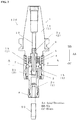
- FIG. 1 is an internal structure diagram of a machining tool 100 (Example 1) according to the present invention.
- Machining tool 100 includes an upper body 1, a holder body 2, a fastening nut 8, and a clamp cover 3.
- Upper body 1 is configured to be detachably connected to a host device such as a machine tool or a robot.
- FIG. 1 shows a shank, which is joining section 1a to be connected to a machine tool spindle.
- Upper body 1 has a cylindrical part 1b at the lower part of joining section 1a.
- Holder body 2 includes a projection part 2a, the upper part thereof, a body part 2b, the central part thereof, and a collet chuck 2c, the lower end thereof.
- Holder body 2 is attached to cylindrical part 1b of upper body 1 with projection part 2a being a head portion.
- body part 2b of holder body 2 is fitted into cylindrical part 1b of upper body 1.
- Collet chuck 2c grips a tool 20.
- tool 20 is a tap (a tool for drilling threaded holes), although the tool is not limited to this.
- Fastening nut 8 is configured to be screwed to the lower end of holder body 2 to fasten tool 20 to holder body 2.
- Clamp cover 3 is slidably mounted on the outside of cylindrical part 1b.
- Joining section 1a of upper body 1 is provided with a flow channel 10 of a coolant to cool a tool, cannel 10 being formed in a U-shape.
- upper body 1 is provided with a first spring 5, which is formed so as to wind around the outer periphery of cylindrical part 1b.
- Holder body 2 is provided with a second spring 6, which is formed so as to wind around the outer periphery of projection part 2a .
- a push-out fitting 4 is provided to the second spring 6.
- projection part 2a which is configured to be rod-shaped
- body part 2b which constitutes the central part of holder body 2
- Machining tool 100 includes steel balls 7, which are held in through holes 13, through holes 13 being provided to cylindrical part 1b.
- Each steel ball 7 protrudes from each through hole 13, one side of each steel ball 7 facing body part 2b of holder body 2, and the other side of each steel ball 7 facing the inner periphery of clamp cover 3.
- Body part 2b of holder body 2 is provided with V-shaped grooves 14 on the outer periphery of body part 2b. Each of grooves 14 is configured to support each steel ball 7.
- Clamp cover 3 is provided with inclined surfaces 15 on the inner periphery thereof. Each of the inclined surfaces 15 is configured to support each steel ball 7.
- FIG. 2 is an internal structure diagram of a machining tool 100 (Example 2) according to another embodiment of the present invention. Machining tool 100 of Example 2 differs from machining tool 100 of Example 1 shown in FIG. 1 only in the configuration of the upper part of a holder body 2.
- a projection part 2a configured to be rod-shaped is separately formed from a body part 2b, which is the central part of holder body 2, so that projection part 2a and body part 2b are not formed in one piece.
- the upper part of projection part 2a is fitted into a joining section 1a of an upper body 1, and the lower part of projection part 2a is fitted into a recessed part of body part 2b.
- Projection part 2a is axially provided with a flow channel 10 of a coolant in the center thereof, and U-shaped flow channel 10 is provided to body part 2b.
- the configuration of the other components in this example is the same as that of the example shown in FIG. 1 .
- FIG. 3 is an enlarged view of a steel ball 7 and its surrounding area shown FIG. 1 .
- both first spring 5 and second spring 6 are configured to downwardly bias clamp cover 3 and body part 2b respectively in an axial direction.
- One side of each V-shaped groove 14 has an angle of ⁇ 1 with respect to the axial direction, and the other side of each V-shaped groove 14 has an angle of ⁇ 2 with respect to the axial direction.
- the angles of ⁇ 1 and ⁇ 2 may be configured to be the same or different.
- Inclined surface 15 has an angle of ⁇ 3 with respect to the axial direction.
- first spring 5 and second spring 6 bias clamp cover 3 and body part 2b respectively in an axial direction towards tool 20, steel ball 7 is pushed downward towards tool 20 by way of inclined surface 15 having the angle ⁇ 3 and the side of groove 14 having the angle ⁇ 1, whereby steel ball 7 is held on the lower end surface of through hole 13.
- Cylindrical part 1b of upper body 1 is a fixed part, and body part 2b of holder body 2, which is a movable part, is held by steel balls 7.
- the weight of holder body 2 is applied to each of steel balls 7 at the point where one side of groove 14 forming the angle ⁇ 1 contacts with steel ball 7, and the weight of clamp cover 3 is applied to each of steel balls 7 at the point where inclined surface 15 contacts with steel ball 7.
- there is a second gap ⁇ t between the point where steel ball 7 contacts with inclined surface 15 and the end point of inclined surface 15.
- clamp cover 3 is provided with a cavity 11 that is formed into a hemispherical shape. Sliding the clamp cover upward to oppose the biasing force caused by first spring 5 allows steel ball 7 to be fitted into cavity 11. If steel ball 7 moves towards the outside of cylindrical part 1b, steel ball 7 is disengaged from V-shaped groove 14 of holder body 2. In this state, holder body 2 can be removed from upper body 1 by pulling down holder body 2.
- FIG. 4 is a view to illustrate the operation of the components shown in FIG. 3 .
- This view shows how the components operate when push-back force 25 caused by tool 20 is applied upwardly to holder body 2.
- Steel ball 7 is pushed at the point where the side of groove 14, which forms angle ⁇ 2, contacts with steel ball 7, and moves upwardly by first gap ⁇ c to contact with the upper end surface of through hole 13.
- Second spring 6 shrinks as holder body 2 is pushed upward.
- First spring 5 also shrinks as clamp cover 3 is pushed upwardly at the point where steel ball 7 contacts with inclined surface 15.
- Push-back force 25 results in the shrinking of both first spring 5 and second spring 6.
- Steel ball 7 moves upwardly in the axial direction, and does not move in the direction orthogonal to the axial direction.
- FIG. 5 is another view to illustrate the operation of the components shown in FIG. 3 .
- This view shows the operation of the components when tensile force 26 caused by tool 20 is applied downwardly to holder body 2.
- Steel ball 7 is pushed downward at the point where the side of groove 14, which forms the angle ⁇ 1, contacts with steel ball 7, but the lower end surface of through hole 13 prevents steel ball 7 from being moved in the axial direction. Therefore, steel ball 7 moves in the direction orthogonal to the axial direction by second gap ⁇ t.
- steel ball 7 pushes inclined surface 15 upwardly in the axial direction, by which first spring 5 shrinks, and second spring 6 extends downward.
- the tensile force causes first spring 5 to shrink and second spring 6 to extend.
- Steel ball 7 moves in the direction orthogonal to the axial direction, and does not move downwardly in the axial direction.
- FIG. 6 shows another example of a configuration formed by a clamp cover and a first spring.
- first spring 5 is configured to bias clamp cover 3 downwardly in the axial direction.
- first spring 5 is configured to bias a clamp cover 3 upwardly in the axial direction.
- hemispherical cavity 11 of clamp cover 3 is provided to the upper part of clamp cover 3. The description of the movement of steel ball 7 is omitted because this is the same as that described with reference to FIGS. 4 and 5 .
- FIG. 7 is a cross-sectional view taken along line A-A of FIG. 1 showing a circular shape, and illustrates the state where steel balls are mounted.
- Cylindrical part 1b, body part 2b, and clamp cover 3 are respectively configured to be in a circular shape. If a steel ball 7 rests in through hole 13, steel ball 7 will not exit from the inside of cylinder 1b because the walls of through hole 13 are configured to be tapered. Also, even if machining tool 100 bites into a workpiece to result in twisting of holder body 2, the positional relationships between cylindrical part 1b of upper body 1, holder body 2, and steel balls 7 are not changed.
- the present invention has various applications as a machining tool capable of performing minute expansion and contraction in an axial direction.
Landscapes
- Engineering & Computer Science (AREA)
- Mechanical Engineering (AREA)
- Gripping On Spindles (AREA)
- Jigs For Machine Tools (AREA)
Abstract
Description
- The present invention relates to a machining tool, and more particularly to a machining tool capable of performing minute expansion and contraction in an axial direction.
- Patent Document 1 (Japanese Unexamined Patent Application Publication No.
2012-11474 FIG. 8 . This machining tool consists of anupper body 1 and aholder body 2. The upper part ofupper body 1 is configured to be attached to a machine tool spindle, and the lower end ofholder body 2 is configured such that a tool (tap) is attached thereto. Becauseholder body 2 is supported by a firstelastic body 32 and a secondelastic body 33, both being ring-shaped,holder body 2 is capable of performing minute expansion and contraction of 0.1 to 0.5 mm when a screw hole is drilled in a workpiece with the tool (tap), so thatholder body 2 is subjected to a push-back force or a tensile force caused by the tap. Specifically, the firstelastic body 32 shrinks by the push-back force 25 of the tap, and the secondelastic body 33 shrinks by thetensile force 26 of the tap. However, because the first and secondelastic bodies - Patent Document 2 (Japanese Unexamined Patent Application Publication No.
2004-142033 -
- Patent Document 1: Japanese Unexamined Patent Application Publication No.
2012-11474 - Patent Document 2: Japanese Unexamined Patent Application Publication No.
2004-142033 - In order to address the aforesaid problems involving conventional machining tools, one of the objectives of the present invention is to provide a machining tool that is capable of performing accurate and stable minute expansion and contraction.
- According to an embodiment of the present invention, a machining tool includes an upper body including a joining section that is configured to be attached to a host device, and a cylindrical part at a lower part thereof; a first spring that is provided to the cylindrical part on an outer periphery wall thereof; a holder body including a projection part around which a second spring is wound, a body part, which constitutes a central portion thereof, and a collet chuck configured to grip a tool at a lower end thereof, the holder body being configured to be removably attached to the cylindrical part of the upper body; a clamp cover configured to cover the first spring, and slidably mounted on an outside of the cylindrical part; at least one steel ball that is configured to be held in a through hole of the cylindrical part, one side of the steel ball facing the body part of the holder body, and the other side of the steel ball facing an inner periphery of the clamp cover; a V-shaped groove provided to an outer periphery wall of the body part to support the steel ball; an inclined surface that is provided to an inner periphery of the clamp cover, configured to be inclined towards an axial direction, so as to support the steel ball; and wherein sliding the clamp cover in the axial direction allows the holder body to be attached to and detached from the upper body with one-touch action, wherein the through hole is provided with a first gap (Δc) that permits the steel ball to move in the axial direction, and the clamp cover is provided with a second gap (Δt) on the inside thereof, the second gap (Δt) permitting the steel ball to move in a direction orthogonal to the axial direction, wherein if a push-back force caused by the tool is applied, the steel ball moves across the first gap (Δc) in the axial direction with opposing the biasing force caused by the first spring and the second spring, and wherein if a tensile force caused by the tool is applied, the second spring extends, and the steel ball moves across the second gap (Δt) in the direction orthogonal to the axial direction with opposing the biasing force caused by the first spring.
- The clamp cover is preferably provided with a cavity that is configured to accommodate the steel ball moving towards the outside of the cylindrical part.
- A machining tool according to the present invention exhibits the following advantageous effects.
- 1. The machining tool is provided with a first spring, a second spring, and at least one steel ball, which enable the machining tool to perform minute expansion and contraction. The use of the springs does not cause sagging, and reduces the variability in elasticity, unlike a rubber used as an elastic body, which can provide accurate and stable minute expansion and contraction of the machining tool based on the modulus of elasticity.
- 2. The through hole is provided with a first gap (Δc) that permits the steel ball to move in the axial direction, and the clamp cover is provided with a second gap (Δt) on the inside thereof, the second gap (Δt) permitting the steel ball to move in a direction orthogonal to the axial direction. Because of these features, the machining tool can deal with two forces of a push-back force, and a tensile force caused by a tap.
- 3. The machining tool is provided with a configuration such that the steel ball is engaged with a V-shaped groove provided to the outer periphery of a body part, and the steel ball can be pushed into a cavity formed on the inner periphery of a clamp, so that the holder body can be easily attached to and detached from the upper body due to the movement of the steel ball.
- Because of the configuration in which the clamp cover is provided with the cavity that accommodates the steel ball moving towards the outside from the through hole, the holder body can be detached from the upper body in such a way that the clamp cover is slid to allow the steel ball to be moved from the through hole into the cavity so that the steel ball is disengaged from the V-shaped groove. Conversely, if the removed holder body is attached again to the cylindrical part of the upper body, and the clamp cover is restored to the original position, the steel ball engages with the V-shaped groove, allowing the holder body to be attached to the upper body with one-touch action.
- Because the machining tool is configured such that if the push-back force is applied, the steel ball moves across the first gap (Δc) opposing the biasing force caused by the first spring and the second spring, the machining tool can perform minute expansion and contraction in response to a strong load of the push-back force, and a relatively weak load of the tensile force.
-
-
FIG. 1 is an internal structure diagram of a machining tool (Example 1) according to the present invention. -
FIG. 2 is an internal structure diagram of a machining tool (Example 2) according to the present invention. -
FIG. 3 is an enlarged view of asteel ball 7 and its surrounding area shownFIG. 1 . -
FIG. 4 is a view to illustrate the operation of the components shown inFIG. 3 . -
FIG. 5 is another view to illustrate the operation of the components shown inFIG. 3 . -
FIG. 6 shows another example of a configuration formed by a clamp cover and a first spring. -
FIG. 7 is a cross-sectional view taken along line A-A ofFIG. 1 showing a circular shape, and illustrates the state where steel balls are mounted. -
FIG. 8 is an illustration drawing of a conventional machining tool capable of performing small expansion and contraction. - Hereinafter, a machining tool according to the present invention will be described in detail with reference to the accompanying drawings.
-
FIG. 1 is an internal structure diagram of a machining tool 100 (Example 1) according to the present invention.Machining tool 100 includes anupper body 1, aholder body 2, a fasteningnut 8, and aclamp cover 3.Upper body 1 is configured to be detachably connected to a host device such as a machine tool or a robot.FIG. 1 shows a shank, which is joining section 1a to be connected to a machine tool spindle.Upper body 1 has a cylindrical part 1b at the lower part of joining section 1a.Holder body 2 includes a projection part 2a, the upper part thereof, a body part 2b, the central part thereof, and a collet chuck 2c, the lower end thereof.Holder body 2 is attached to cylindrical part 1b ofupper body 1 with projection part 2a being a head portion. In this state whereholder body 2 has been attached to cylindrical part 1b, body part 2b ofholder body 2 is fitted into cylindrical part 1b ofupper body 1. Collet chuck 2c grips atool 20. In this example,tool 20 is a tap (a tool for drilling threaded holes), although the tool is not limited to this. Fasteningnut 8 is configured to be screwed to the lower end ofholder body 2 to fastentool 20 to holderbody 2.Clamp cover 3 is slidably mounted on the outside of cylindrical part 1b. Joining section 1a ofupper body 1 is provided with aflow channel 10 of a coolant to cool a tool,cannel 10 being formed in a U-shape. - As shown in
FIG. 1 ,upper body 1 is provided with afirst spring 5, which is formed so as to wind around the outer periphery of cylindrical part 1b.Holder body 2 is provided with asecond spring 6, which is formed so as to wind around the outer periphery of projection part 2a . In order to adjust the biasing force ofsecond spring 6, a push-out fitting 4 is provided to thesecond spring 6. In this example, projection part 2a, which is configured to be rod-shaped, and body part 2b, which constitutes the central part ofholder body 2, are formed in one piece.Machining tool 100 includessteel balls 7, which are held in throughholes 13, throughholes 13 being provided to cylindrical part 1b. Eachsteel ball 7 protrudes from each throughhole 13, one side of eachsteel ball 7 facing body part 2b ofholder body 2, and the other side of eachsteel ball 7 facing the inner periphery ofclamp cover 3. Body part 2b ofholder body 2 is provided with V-shapedgrooves 14 on the outer periphery of body part 2b. Each ofgrooves 14 is configured to support eachsteel ball 7.Clamp cover 3 is provided withinclined surfaces 15 on the inner periphery thereof. Each of theinclined surfaces 15 is configured to support eachsteel ball 7. -
FIG. 2 is an internal structure diagram of a machining tool 100 (Example 2) according to another embodiment of the present invention.Machining tool 100 of Example 2 differs from machiningtool 100 of Example 1 shown inFIG. 1 only in the configuration of the upper part of aholder body 2. In the example shown inFIG. 2 , a projection part 2a configured to be rod-shaped is separately formed from a body part 2b, which is the central part ofholder body 2, so that projection part 2a and body part 2b are not formed in one piece. The upper part of projection part 2a is fitted into a joining section 1a of anupper body 1, and the lower part of projection part 2a is fitted into a recessed part of body part 2b. Projection part 2a is axially provided with aflow channel 10 of a coolant in the center thereof, andU-shaped flow channel 10 is provided to body part 2b. The configuration of the other components in this example is the same as that of the example shown inFIG. 1 . -
FIG. 3 is an enlarged view of asteel ball 7 and its surrounding area shownFIG. 1 . As shown inFIG. 3 , in the state whereholder body 2 has been fitted intoupper body 1, bothfirst spring 5 andsecond spring 6 are configured to downwardlybias clamp cover 3 and body part 2b respectively in an axial direction. One side of each V-shapedgroove 14 has an angle of θ1 with respect to the axial direction, and the other side of each V-shapedgroove 14 has an angle of θ2 with respect to the axial direction. The angles of θ1 and θ2 may be configured to be the same or different.Inclined surface 15 has an angle of θ3 with respect to the axial direction. Becausefirst spring 5 andsecond spring 6bias clamp cover 3 and body part 2b respectively in an axial direction towardstool 20,steel ball 7 is pushed downward towardstool 20 by way ofinclined surface 15 having the angle θ3 and the side ofgroove 14 having the angle θ1, wherebysteel ball 7 is held on the lower end surface of throughhole 13. Cylindrical part 1b ofupper body 1 is a fixed part, and body part 2b ofholder body 2, which is a movable part, is held bysteel balls 7. Also, the weight ofholder body 2 is applied to each ofsteel balls 7 at the point where one side ofgroove 14 forming the angle θ1 contacts withsteel ball 7, and the weight ofclamp cover 3 is applied to each ofsteel balls 7 at the point whereinclined surface 15 contacts withsteel ball 7. In this state, there is a first gap Δc betweensteel ball 7 and the upper end surface of throughhole 13. Also, there is a second gap Δt between the point wheresteel ball 7 contacts withinclined surface 15 and the end point ofinclined surface 15. - As shown in
FIG. 3 , clampcover 3 is provided with a cavity 11 that is formed into a hemispherical shape. Sliding the clamp cover upward to oppose the biasing force caused byfirst spring 5 allowssteel ball 7 to be fitted into cavity 11. Ifsteel ball 7 moves towards the outside of cylindrical part 1b,steel ball 7 is disengaged from V-shapedgroove 14 ofholder body 2. In this state,holder body 2 can be removed fromupper body 1 by pulling downholder body 2. Conversely, if removedholder body 2 is attached again to cylindrical part 1b ofupper body 1, and clampcover 3 is restored to the original position by the force offirst spring 5,steel ball 7 engages with V-shapedgroove 14, so thatholder body 2 is locked ontoupper body 1, allowingholder body 2 to be attached toupper body 1 with one-touch action. -
FIG. 4 is a view to illustrate the operation of the components shown inFIG. 3 . This view shows how the components operate when push-back force 25 caused bytool 20 is applied upwardly toholder body 2.Steel ball 7 is pushed at the point where the side ofgroove 14, which forms angle θ2, contacts withsteel ball 7, and moves upwardly by first gap Δc to contact with the upper end surface of throughhole 13.Second spring 6 shrinks asholder body 2 is pushed upward.First spring 5 also shrinks asclamp cover 3 is pushed upwardly at the point wheresteel ball 7 contacts withinclined surface 15. Push-back force 25 results in the shrinking of bothfirst spring 5 andsecond spring 6.Steel ball 7 moves upwardly in the axial direction, and does not move in the direction orthogonal to the axial direction. -
FIG. 5 is another view to illustrate the operation of the components shown inFIG. 3 . This view shows the operation of the components whentensile force 26 caused bytool 20 is applied downwardly toholder body 2.Steel ball 7 is pushed downward at the point where the side ofgroove 14, which forms the angle θ1, contacts withsteel ball 7, but the lower end surface of throughhole 13 preventssteel ball 7 from being moved in the axial direction. Therefore,steel ball 7 moves in the direction orthogonal to the axial direction by second gap Δt. At the same time,steel ball 7 pushes inclinedsurface 15 upwardly in the axial direction, by whichfirst spring 5 shrinks, andsecond spring 6 extends downward. Thus, the tensile force causesfirst spring 5 to shrink andsecond spring 6 to extend.Steel ball 7 moves in the direction orthogonal to the axial direction, and does not move downwardly in the axial direction. -
FIG. 6 shows another example of a configuration formed by a clamp cover and a first spring. In the example shown inFIG. 3 , in the state whereholder body 2 has been fitted intoupper body 1,first spring 5 is configured to biasclamp cover 3 downwardly in the axial direction. However, as shown inFIG. 6 ,first spring 5 is configured to bias aclamp cover 3 upwardly in the axial direction. In such a case, hemispherical cavity 11 ofclamp cover 3 is provided to the upper part ofclamp cover 3. The description of the movement ofsteel ball 7 is omitted because this is the same as that described with reference toFIGS. 4 and5 . -
FIG. 7 is a cross-sectional view taken along line A-A ofFIG. 1 showing a circular shape, and illustrates the state where steel balls are mounted. Cylindrical part 1b, body part 2b, and clampcover 3 are respectively configured to be in a circular shape. If asteel ball 7 rests in throughhole 13,steel ball 7 will not exit from the inside of cylinder 1b because the walls of throughhole 13 are configured to be tapered. Also, even ifmachining tool 100 bites into a workpiece to result in twisting ofholder body 2, the positional relationships between cylindrical part 1b ofupper body 1,holder body 2, andsteel balls 7 are not changed. - The present invention has various applications as a machining tool capable of performing minute expansion and contraction in an axial direction.
-
- 1
- upper body
- 1a
- joining section
- 1b
- cylindrical part
- 2
- holder body
- 2a
- projection part
- 2b
- body part 2b
- 2c
- collet chuck
- 3
- clamp cover
- 4
- push-out fitting
- 5
- first spring
- 6
- second spring
- 7
- steel ball
- 8
- fastening nut
- 10
- flow channel
- 11
- hemispherical cavity
- 13
- through hole
- 14
- groove
- 15
- inclined surface
- 20
- tool (tap)
- 25
- push-back force
- 26
- tensile force
- Δc
- first gap
- Δt
- second gap
- 32
- first elastic body
- 33
- second elastic body
- 100
- machining tool
Claims (2)
- A machining tool comprising:an upper body comprising a joining section that is configured to be attached to a host device, and a cylindrical part at a lower part thereof;a first spring that is provided to the cylindrical part on an outer periphery wall thereof;a holder body comprising a projection part around which a second spring is wound, a body part, which constitutes a central portion thereof, and a collet chuck configured to grip a tool at a lower end thereof, the holder body being configured to be removably attached to the cylindrical part of the upper body;a clamp cover configured to cover the first spring, and slidably mounted on an outside of the cylindrical part;at least one steel ball that is configured to be held in a through hole of the cylindrical part, one side of the steel ball facing the body part of the holder body, and the other side of the steel ball facing an inner periphery of the clamp cover;a V-shaped groove provided to an outer periphery wall of the body part to support the steel ball;an inclined surface that is provided to an inner periphery of the clamp cover, configured to be inclined towards an axial direction, so as to support the steel ball;wherein sliding the clamp cover in the axial direction allows the holder body to be attached to and detached from the upper body with one-touch action,wherein the through hole is provided with a first gap (Δc) that permits the steel ball to move in the axial direction, and the clamp cover is provided with a second gap (Δt) on the inside thereof, the second gap (Δt) permitting the steel ball to move in a direction orthogonal to the axial direction,wherein if a push-back force caused by the tool is applied, the steel ball moves across the first gap (Δc) in the axial direction with opposition to the biasing force caused by the first spring and the second spring, andwherein if a tensile force caused by the tool is applied, the second spring extends, and the steel ball moves across the second gap (Δt) in the direction orthogonal to the axial direction with opposition to the biasing force caused by the first spring.
- The machining tool of Claim 1, wherein the clamp cover is provided with a cavity that is configured to accommodate the steel ball moving towards the outside of the cylindrical part.
Applications Claiming Priority (2)
| Application Number | Priority Date | Filing Date | Title |
|---|---|---|---|
| JP2018128243A JP6467546B1 (en) | 2018-07-05 | 2018-07-05 | Machining tools |
| PCT/JP2019/026917 WO2020009244A1 (en) | 2018-07-05 | 2019-07-05 | Machining tool |
Publications (4)
| Publication Number | Publication Date |
|---|---|
| EP3819075A1 true EP3819075A1 (en) | 2021-05-12 |
| EP3819075A4 EP3819075A4 (en) | 2022-03-30 |
| EP3819075C0 EP3819075C0 (en) | 2026-01-28 |
| EP3819075B1 EP3819075B1 (en) | 2026-01-28 |
Family
ID=65356006
Family Applications (1)
| Application Number | Title | Priority Date | Filing Date |
|---|---|---|---|
| EP19831371.0A Active EP3819075B1 (en) | 2018-07-05 | 2019-07-05 | Machining tool |
Country Status (4)
| Country | Link |
|---|---|
| EP (1) | EP3819075B1 (en) |
| JP (1) | JP6467546B1 (en) |
| CN (1) | CN112351860B (en) |
| WO (1) | WO2020009244A1 (en) |
Cited By (2)
| Publication number | Priority date | Publication date | Assignee | Title |
|---|---|---|---|---|
| EP4166263A1 (en) * | 2021-10-14 | 2023-04-19 | Sugino Machine Limited | Processing tool |
| US12661722B2 (en) * | 2022-08-30 | 2026-06-23 | Sugino Machine Limited | Deburring tool |
Families Citing this family (3)
| Publication number | Priority date | Publication date | Assignee | Title |
|---|---|---|---|---|
| JP6989196B1 (en) * | 2021-08-31 | 2022-01-05 | カトウ工機株式会社 | Deburring holder |
| JP7263582B1 (en) | 2022-03-01 | 2023-04-24 | 株式会社スギノマシン | processing tools |
| WO2025023488A1 (en) * | 2023-07-26 | 2025-01-30 | 삼성전자 주식회사 | Exterior cover and cutting device for manufacturing same |
Family Cites Families (17)
| Publication number | Priority date | Publication date | Assignee | Title |
|---|---|---|---|---|
| US3521314A (en) * | 1967-09-19 | 1970-07-21 | Numertap Inc | Torque limiting tool holder |
| JPS5124630Y2 (en) * | 1971-09-07 | 1976-06-23 | ||
| JPH0890313A (en) * | 1994-09-22 | 1996-04-09 | San Flex Kk | Flexible power transmission |
| JP3017951B2 (en) * | 1996-12-24 | 2000-03-13 | カトウ工機株式会社 | Tap holder device |
| DE69826014T2 (en) * | 1997-02-28 | 2005-09-15 | Kabushiki Kaisha Miyanaga, Miki | SHAFT MOUNTING STRUCTURE |
| DE19739466A1 (en) * | 1997-09-09 | 1999-03-11 | Franz Haimer | Tool holder arrangement for revolving tool, especially for thread cutting tool |
| JP2001028721A (en) * | 1999-07-14 | 2001-01-30 | Canon Inc | Electronic device and method for connecting external interface in electronic device |
| DE60040246D1 (en) * | 1999-10-19 | 2008-10-23 | Miyanaga Miki Kk | Cutting tool for quick change chuck |
| JP4344880B2 (en) * | 2002-10-24 | 2009-10-14 | カトウ工機株式会社 | Tap holder with axial micro-slide mechanism |
| JP5073321B2 (en) * | 2007-03-07 | 2012-11-14 | 株式会社マキタ | Bit setting device for rotary tools |
| CN100522427C (en) * | 2007-03-10 | 2009-08-05 | 朱明� | Machine tool quick changing chuck system |
| CN201613372U (en) * | 2009-12-29 | 2010-10-27 | 苏州宝时得电动工具有限公司 | Chuck and electric tool using same |
| JP5470659B2 (en) | 2010-06-29 | 2014-04-16 | カトウ工機株式会社 | Tap holder |
| JP2012240162A (en) * | 2011-05-20 | 2012-12-10 | Nachi Fujikoshi Corp | Quick changer device |
| CN102886541B (en) * | 2011-07-22 | 2015-12-23 | 昆山义成工具有限公司 | Clamping device |
| DE102013103937B4 (en) * | 2013-04-18 | 2014-12-04 | Bilz Werkzeugfabrik Gmbh & Co. Kg | Quick change system for a tool holder |
| US9561581B2 (en) * | 2015-01-22 | 2017-02-07 | Shu-Hui Yeh | Quick-removal socket tool |
-
2018
- 2018-07-05 JP JP2018128243A patent/JP6467546B1/en active Active
-
2019
- 2019-07-05 CN CN201980043321.0A patent/CN112351860B/en active Active
- 2019-07-05 EP EP19831371.0A patent/EP3819075B1/en active Active
- 2019-07-05 WO PCT/JP2019/026917 patent/WO2020009244A1/en not_active Ceased
Cited By (3)
| Publication number | Priority date | Publication date | Assignee | Title |
|---|---|---|---|---|
| EP4166263A1 (en) * | 2021-10-14 | 2023-04-19 | Sugino Machine Limited | Processing tool |
| US12623294B2 (en) | 2021-10-14 | 2026-05-12 | Sugino Machine Limited | Processing tool |
| US12661722B2 (en) * | 2022-08-30 | 2026-06-23 | Sugino Machine Limited | Deburring tool |
Also Published As
| Publication number | Publication date |
|---|---|
| CN112351860B (en) | 2022-10-25 |
| JP6467546B1 (en) | 2019-02-13 |
| EP3819075C0 (en) | 2026-01-28 |
| EP3819075B1 (en) | 2026-01-28 |
| CN112351860A (en) | 2021-02-09 |
| JP2020006460A (en) | 2020-01-16 |
| EP3819075A4 (en) | 2022-03-30 |
| WO2020009244A1 (en) | 2020-01-09 |
Similar Documents
| Publication | Publication Date | Title |
|---|---|---|
| EP3819075B1 (en) | Machining tool | |
| RU2342241C2 (en) | Clamp assembly | |
| EP1177847B2 (en) | Tap holder | |
| KR20140039214A (en) | Holder device | |
| JP3198457U (en) | Flare tool | |
| US11154937B2 (en) | Tool holder | |
| US5040931A (en) | Coupling mechanism | |
| KR101575567B1 (en) | The boring bar | |
| US6883407B2 (en) | Expanding collet assembly for pick-off spindle | |
| KR20160106416A (en) | Length adjustment structure of machine workpiece | |
| EP4566742A1 (en) | Machine tool, chuck gripping force detection method, and chuck fastening amount setting method | |
| US7708506B2 (en) | Self-synchronizing tap driver for rigid tapping with starting force adjustment | |
| JP2018192565A5 (en) | ||
| US8056905B1 (en) | Computerized numeric control toolholder tightening fixture | |
| KR101628015B1 (en) | The boring bar | |
| JP5504994B2 (en) | Tap holder | |
| CN109226799B (en) | Precise elastic chuck | |
| RU163809U1 (en) | BORING TOOL | |
| CN101422865B (en) | Clamping device and method for machining workpiece | |
| KR101581649B1 (en) | Method of moving saddle for boring bar and manufacturing method using that | |
| JPH04507381A (en) | Tools for use in machine tools | |
| JP2007054948A (en) | Diaphragm chuck | |
| JP6573300B1 (en) | Machining tools | |
| JP2016016494A (en) | Mounting device and mounting method of member to be mounted | |
| CN112276607A (en) | CNC adds clamping apparatus |
Legal Events
| Date | Code | Title | Description |
|---|---|---|---|
| STAA | Information on the status of an ep patent application or granted ep patent |
Free format text: STATUS: THE INTERNATIONAL PUBLICATION HAS BEEN MADE |
|
| PUAI | Public reference made under article 153(3) epc to a published international application that has entered the european phase |
Free format text: ORIGINAL CODE: 0009012 |
|
| STAA | Information on the status of an ep patent application or granted ep patent |
Free format text: STATUS: REQUEST FOR EXAMINATION WAS MADE |
|
| 17P | Request for examination filed |
Effective date: 20201215 |
|
| AK | Designated contracting states |
Kind code of ref document: A1 Designated state(s): AL AT BE BG CH CY CZ DE DK EE ES FI FR GB GR HR HU IE IS IT LI LT LU LV MC MK MT NL NO PL PT RO RS SE SI SK SM TR |
|
| DAV | Request for validation of the european patent (deleted) | ||
| DAX | Request for extension of the european patent (deleted) | ||
| REG | Reference to a national code |
Free format text: PREVIOUS MAIN CLASS: B23Q0003120000 Ipc: B23B0031107000 Ref country code: DE Ref legal event code: R079 Ref document number: 602019080835 Country of ref document: DE Free format text: PREVIOUS MAIN CLASS: B23Q0003120000 Ipc: B23B0031107000 |
|
| A4 | Supplementary search report drawn up and despatched |
Effective date: 20220228 |
|
| RIC1 | Information provided on ipc code assigned before grant |
Ipc: B23B 31/20 20060101ALI20220222BHEP Ipc: B23B 31/08 20060101ALI20220222BHEP Ipc: B23B 31/02 20060101ALI20220222BHEP Ipc: B23G 1/46 20060101ALI20220222BHEP Ipc: B23B 31/107 20060101AFI20220222BHEP |
|
| GRAP | Despatch of communication of intention to grant a patent |
Free format text: ORIGINAL CODE: EPIDOSNIGR1 |
|
| STAA | Information on the status of an ep patent application or granted ep patent |
Free format text: STATUS: GRANT OF PATENT IS INTENDED |
|
| INTG | Intention to grant announced |
Effective date: 20250926 |
|
| GRAS | Grant fee paid |
Free format text: ORIGINAL CODE: EPIDOSNIGR3 |
|
| GRAA | (expected) grant |
Free format text: ORIGINAL CODE: 0009210 |
|
| STAA | Information on the status of an ep patent application or granted ep patent |
Free format text: STATUS: THE PATENT HAS BEEN GRANTED |
|
| AK | Designated contracting states |
Kind code of ref document: B1 Designated state(s): AL AT BE BG CH CY CZ DE DK EE ES FI FR GB GR HR HU IE IS IT LI LT LU LV MC MK MT NL NO PL PT RO RS SE SI SK SM TR |
|
| REG | Reference to a national code |
Ref country code: CH Ref legal event code: F10 Free format text: ST27 STATUS EVENT CODE: U-0-0-F10-F00 (AS PROVIDED BY THE NATIONAL OFFICE) Effective date: 20260128 Ref country code: GB Ref legal event code: FG4D |
|
| REG | Reference to a national code |
Ref country code: DE Ref legal event code: R096 Ref document number: 602019080835 Country of ref document: DE |
|
| REG | Reference to a national code |
Ref country code: IE Ref legal event code: FG4D |
|
| U01 | Request for unitary effect filed |
Effective date: 20260227 |
|
| U07 | Unitary effect registered |
Designated state(s): AT BE BG DE DK EE FI FR IT LT LU LV MT NL PT RO SE SI Effective date: 20260305 |
|
| PG25 | Lapsed in a contracting state [announced via postgrant information from national office to epo] |
Ref country code: RS Free format text: LAPSE BECAUSE OF FAILURE TO SUBMIT A TRANSLATION OF THE DESCRIPTION OR TO PAY THE FEE WITHIN THE PRESCRIBED TIME-LIMIT Effective date: 20260428 |
|
| PG25 | Lapsed in a contracting state [announced via postgrant information from national office to epo] |
Ref country code: ES Free format text: LAPSE BECAUSE OF FAILURE TO SUBMIT A TRANSLATION OF THE DESCRIPTION OR TO PAY THE FEE WITHIN THE PRESCRIBED TIME-LIMIT Effective date: 20260128 |
|
| PG25 | Lapsed in a contracting state [announced via postgrant information from national office to epo] |
Ref country code: PL Free format text: LAPSE BECAUSE OF FAILURE TO SUBMIT A TRANSLATION OF THE DESCRIPTION OR TO PAY THE FEE WITHIN THE PRESCRIBED TIME-LIMIT Effective date: 20260128 |
|
| PG25 | Lapsed in a contracting state [announced via postgrant information from national office to epo] |
Ref country code: GR Free format text: LAPSE BECAUSE OF FAILURE TO SUBMIT A TRANSLATION OF THE DESCRIPTION OR TO PAY THE FEE WITHIN THE PRESCRIBED TIME-LIMIT Effective date: 20260429 |
|
| PG25 | Lapsed in a contracting state [announced via postgrant information from national office to epo] |
Ref country code: NO Free format text: LAPSE BECAUSE OF FAILURE TO SUBMIT A TRANSLATION OF THE DESCRIPTION OR TO PAY THE FEE WITHIN THE PRESCRIBED TIME-LIMIT Effective date: 20260428 |
|
| PG25 | Lapsed in a contracting state [announced via postgrant information from national office to epo] |
Ref country code: HR Free format text: LAPSE BECAUSE OF FAILURE TO SUBMIT A TRANSLATION OF THE DESCRIPTION OR TO PAY THE FEE WITHIN THE PRESCRIBED TIME-LIMIT Effective date: 20260128 |
|
| PG25 | Lapsed in a contracting state [announced via postgrant information from national office to epo] |
Ref country code: IS Free format text: LAPSE BECAUSE OF FAILURE TO SUBMIT A TRANSLATION OF THE DESCRIPTION OR TO PAY THE FEE WITHIN THE PRESCRIBED TIME-LIMIT Effective date: 20260528 |