EP3819063A1 - Manufacturing method for monolithic multi-pipe hydraulic devices shaped as solids of revolution , in particular heat exchangers - Google Patents
Manufacturing method for monolithic multi-pipe hydraulic devices shaped as solids of revolution , in particular heat exchangers Download PDFInfo
- Publication number
- EP3819063A1 EP3819063A1 EP20206036.4A EP20206036A EP3819063A1 EP 3819063 A1 EP3819063 A1 EP 3819063A1 EP 20206036 A EP20206036 A EP 20206036A EP 3819063 A1 EP3819063 A1 EP 3819063A1
- Authority
- EP
- European Patent Office
- Prior art keywords
- plates
- metallic
- ducted
- monolithic
- apertures
- Prior art date
- Legal status (The legal status is an assumption and is not a legal conclusion. Google has not performed a legal analysis and makes no representation as to the accuracy of the status listed.)
- Granted
Links
Images


Classifications
-
- F—MECHANICAL ENGINEERING; LIGHTING; HEATING; WEAPONS; BLASTING
- F28—HEAT EXCHANGE IN GENERAL
- F28D—HEAT-EXCHANGE APPARATUS, NOT PROVIDED FOR IN ANOTHER SUBCLASS, IN WHICH THE HEAT-EXCHANGE MEDIA DO NOT COME INTO DIRECT CONTACT
- F28D9/00—Heat-exchange apparatus having stationary plate-like or laminated conduit assemblies for both heat-exchange media, the media being in contact with different sides of a conduit wall
- F28D9/0031—Heat-exchange apparatus having stationary plate-like or laminated conduit assemblies for both heat-exchange media, the media being in contact with different sides of a conduit wall the conduits for one heat-exchange medium being formed by paired plates touching each other
- F28D9/0043—Heat-exchange apparatus having stationary plate-like or laminated conduit assemblies for both heat-exchange media, the media being in contact with different sides of a conduit wall the conduits for one heat-exchange medium being formed by paired plates touching each other the plates having openings therein for circulation of at least one heat-exchange medium from one conduit to another
- F28D9/005—Heat-exchange apparatus having stationary plate-like or laminated conduit assemblies for both heat-exchange media, the media being in contact with different sides of a conduit wall the conduits for one heat-exchange medium being formed by paired plates touching each other the plates having openings therein for circulation of at least one heat-exchange medium from one conduit to another the plates having openings therein for both heat-exchange media
-
- B—PERFORMING OPERATIONS; TRANSPORTING
- B23—MACHINE TOOLS; METAL-WORKING NOT OTHERWISE PROVIDED FOR
- B23K—SOLDERING OR UNSOLDERING; WELDING; CLADDING OR PLATING BY SOLDERING OR WELDING; CUTTING BY APPLYING HEAT LOCALLY, e.g. FLAME CUTTING; WORKING BY LASER BEAM
- B23K20/00—Non-electric welding by applying impact or other pressure, with or without the application of heat, e.g. cladding or plating
- B23K20/02—Non-electric welding by applying impact or other pressure, with or without the application of heat, e.g. cladding or plating by means of a press ; Diffusion bonding
- B23K20/021—Isostatic pressure welding
-
- B—PERFORMING OPERATIONS; TRANSPORTING
- B23—MACHINE TOOLS; METAL-WORKING NOT OTHERWISE PROVIDED FOR
- B23K—SOLDERING OR UNSOLDERING; WELDING; CLADDING OR PLATING BY SOLDERING OR WELDING; CUTTING BY APPLYING HEAT LOCALLY, e.g. FLAME CUTTING; WORKING BY LASER BEAM
- B23K20/00—Non-electric welding by applying impact or other pressure, with or without the application of heat, e.g. cladding or plating
- B23K20/22—Non-electric welding by applying impact or other pressure, with or without the application of heat, e.g. cladding or plating taking account of the properties of the materials to be welded
- B23K20/227—Non-electric welding by applying impact or other pressure, with or without the application of heat, e.g. cladding or plating taking account of the properties of the materials to be welded with ferrous layer
-
- F—MECHANICAL ENGINEERING; LIGHTING; HEATING; WEAPONS; BLASTING
- F28—HEAT EXCHANGE IN GENERAL
- F28F—DETAILS OF HEAT-EXCHANGE AND HEAT-TRANSFER APPARATUS, OF GENERAL APPLICATION
- F28F7/00—Elements not covered by group F28F1/00, F28F3/00 or F28F5/00
- F28F7/02—Blocks traversed by passages for heat-exchange media
-
- B—PERFORMING OPERATIONS; TRANSPORTING
- B23—MACHINE TOOLS; METAL-WORKING NOT OTHERWISE PROVIDED FOR
- B23K—SOLDERING OR UNSOLDERING; WELDING; CLADDING OR PLATING BY SOLDERING OR WELDING; CUTTING BY APPLYING HEAT LOCALLY, e.g. FLAME CUTTING; WORKING BY LASER BEAM
- B23K2101/00—Articles made by soldering, welding or cutting
- B23K2101/04—Tubular or hollow articles
- B23K2101/14—Heat exchangers
-
- B—PERFORMING OPERATIONS; TRANSPORTING
- B23—MACHINE TOOLS; METAL-WORKING NOT OTHERWISE PROVIDED FOR
- B23K—SOLDERING OR UNSOLDERING; WELDING; CLADDING OR PLATING BY SOLDERING OR WELDING; CUTTING BY APPLYING HEAT LOCALLY, e.g. FLAME CUTTING; WORKING BY LASER BEAM
- B23K2103/00—Materials to be soldered, welded or cut
- B23K2103/02—Iron or ferrous alloys
- B23K2103/04—Steel or steel alloys
-
- B—PERFORMING OPERATIONS; TRANSPORTING
- B23—MACHINE TOOLS; METAL-WORKING NOT OTHERWISE PROVIDED FOR
- B23K—SOLDERING OR UNSOLDERING; WELDING; CLADDING OR PLATING BY SOLDERING OR WELDING; CUTTING BY APPLYING HEAT LOCALLY, e.g. FLAME CUTTING; WORKING BY LASER BEAM
- B23K2103/00—Materials to be soldered, welded or cut
- B23K2103/18—Dissimilar materials
-
- B—PERFORMING OPERATIONS; TRANSPORTING
- B23—MACHINE TOOLS; METAL-WORKING NOT OTHERWISE PROVIDED FOR
- B23K—SOLDERING OR UNSOLDERING; WELDING; CLADDING OR PLATING BY SOLDERING OR WELDING; CUTTING BY APPLYING HEAT LOCALLY, e.g. FLAME CUTTING; WORKING BY LASER BEAM
- B23K2103/00—Materials to be soldered, welded or cut
- B23K2103/18—Dissimilar materials
- B23K2103/26—Alloys of Nickel and Cobalt and Chromium
-
- F—MECHANICAL ENGINEERING; LIGHTING; HEATING; WEAPONS; BLASTING
- F28—HEAT EXCHANGE IN GENERAL
- F28F—DETAILS OF HEAT-EXCHANGE AND HEAT-TRANSFER APPARATUS, OF GENERAL APPLICATION
- F28F2275/00—Fastening; Joining
-
- F—MECHANICAL ENGINEERING; LIGHTING; HEATING; WEAPONS; BLASTING
- F28—HEAT EXCHANGE IN GENERAL
- F28F—DETAILS OF HEAT-EXCHANGE AND HEAT-TRANSFER APPARATUS, OF GENERAL APPLICATION
- F28F2275/00—Fastening; Joining
- F28F2275/06—Fastening; Joining by welding
- F28F2275/061—Fastening; Joining by welding by diffusion bonding
-
- F—MECHANICAL ENGINEERING; LIGHTING; HEATING; WEAPONS; BLASTING
- F28—HEAT EXCHANGE IN GENERAL
- F28F—DETAILS OF HEAT-EXCHANGE AND HEAT-TRANSFER APPARATUS, OF GENERAL APPLICATION
- F28F9/00—Casings; Header boxes; Auxiliary supports for elements; Auxiliary members within casings
- F28F9/001—Casings in the form of plate-like arrangements; Frames enclosing a heat exchange core
-
- F—MECHANICAL ENGINEERING; LIGHTING; HEATING; WEAPONS; BLASTING
- F28—HEAT EXCHANGE IN GENERAL
- F28F—DETAILS OF HEAT-EXCHANGE AND HEAT-TRANSFER APPARATUS, OF GENERAL APPLICATION
- F28F9/00—Casings; Header boxes; Auxiliary supports for elements; Auxiliary members within casings
- F28F9/007—Auxiliary supports for elements
- F28F9/0075—Supports for plates or plate assemblies
Definitions
- This invention relates to a manufacturing method for monolithic multi-pipe hydraulic devices shaped as solids of revolution, in particular heat exchangers with cylindrical symmetry, intended to operate under conditions of elevated temperatures and pressures.
- “Diffusion bonding” technology or “diffusion welding” is a solid-state welding technique that is well known in engineering and used in metalworking; it is capable of joining two metals whether they are the same or not. It works on the principle of solid-state diffusion, in which atoms on two solid, metallic surfaces inter-diffuse over time.
- a type of heat exchanger obtained with this technology is the one called PCHE (Printed Circuit Heat Exchanger), in which the hydraulic circuit is made by superimposing ducted metallic plates, i.e. etched by means of printed circuit technology on one or both of their opposite flat faces, and which are then made monolithic by diffusion welding by applying one or more HUP (Hot Uniaxial Pressure) or HIP (Hot Isostatic pressure) cycles.
- PCHE Print Circuit Heat Exchanger
- HUP Hot Uniaxial Pressure
- HIP Hot Isostatic pressure
- two plates that have channels/grooves mirroring each other are coupled, so as to form a first fluid circuit.
- This element formed by two plates is sealed and degassed using a capsule; following this, a low-pressure HIP cycle is applied.
- the channels are then opened towards the outside by machining and a second, high-pressure HIP cycle is then applied.
- the resulting plates are then ducted on the two outer sides, thus forming a second fluid circuit.
- Multiple elements obtained using this method are stacked and a first HIP cycle is performed at low pressure with the channels of the second circuit closed. These channels are then opened and a final HIP cycle is performed at high pressure.
- the method described as well as all other methods currently used for implementing monolithic heat exchangers, have the limitation that the monolithic product that is obtained has a parallelepiped symmetry, i.e., it consists of a monolithic block formed from the union, by diffusion bonding, of multiple plates having a basically rectangular shape in plan, which have been stacked one on top of the other.
- This compulsory shape entails, on the one hand, with the same fluid flow capacity, a greater volume compared to conventional shell and tube heat exchangers, which have a cylindrical shape, and, on the other hand, make it more difficult to withstand the internal operating pressures, which are usually equal to or greater than 900 bars.
- the purpose of this invention is to provide a manufacturing method for monolithic multi-pipe hydraulic devices, in particular heat exchangers, free of the drawbacks of the prior art, by which a hydraulic device with good mechanical strength, low weight, and high thermal efficiency is obtained, all in a relatively simple, quick, and cost-effective manner.
- the reference number 1 here identifies, as a whole, a monolithic multi-pipe hydraulic device, in the illustrated example one consisting of a heat exchanger.
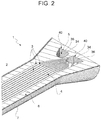
- the hydraulic device or heat exchanger 1 consists of a monolithic metallic block 2 basically shaped like a solid of revolution, in the illustrated example having substantially cylindrical symmetry, and internally provided ( Figure 6 ) with multiple pipes 3 configured ( Figure 2 ) to define at least one hydraulic circuit 4 or, preferably, a pair of hydraulic circuits 4 and 5 ( Figure 2 ), the circuit 5 being illustrated only in one of its end parts for simplicity, the circuits being arranged adjacent to each other inside the hydraulic device 1 so as to promote heat exchange.
- a lateral outer surface 6 of the monolithic metallic block 2, having the shape of a surface of revolution, is tightly wound by a metallic cable 7, preferably made of a steel, for example a stainless steel.
- the metallic cable 7 has been placed under mechanical tension at the time of winding on the lateral surface 6, whereby the metallic cable 7 is tensioned, i.e. statically subjected to a previously induced, and then locked, tensile stress.
- the metallic cable 7 has its opposite ends 8 and 9 firmly fixed, for example welded, to the lateral surface 6, or to respective front surfaces 10, 11 of opposite terminal ends 12, 13 of the monolithic metallic block 2.
- the monolithic hydraulic device 1 described is manufactured by means of a manufacturing method for monolithic multi-pipe hydraulic devices, in particular heat exchangers. This method is an integral part of the invention.
- the manufacturing method of the invention comprises the following steps.
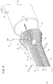
- the step of making/obtaining multiple ducted metallic plates preferably of a first type 14 and of a second type 15 ( Figures 3 and 4 ) each delimited by opposite flat faces 16 (of which only one is clearly visible in Figures 3 and 4 ) and provided, on at least one of these flat faces 16, with one or more grooves or channels 18 extending between first opposite ends 19 of the plates 14, 15 and parallel to second opposite ends 20, 21 of the plates 14, 15 arranged transversely to the first ends 19.
- the plates 14, 15 have a basically rectangular shape (except at the ends 19, where they are wider and basically trapezoidal-shaped) and the ends 20, 21 define opposite lateral sides of the plates 14, 15.
- the grooves or channels 18 are made so as to leave the second ends 20, 21 of the metallic plates 14, 15 solid and free of the grooves or channels 18.
- the stack 22 is subjected to at least one thermomechanical integration cycle by diffusion welding or "diffusion bonding", so as to obtain a single monolithic block from the overlapping metallic plates 14, 15, in this case the monolithic metallic block 2 within which the grooves or channels 18 form multiple pipes 3, forming the above-mentioned at least one hydraulic circuit 4, and preferably a pair of separate and adjacent hydraulic circuits 4, 5.
- the multiple ducted metallic plates 14, 15 have the same shape but are made two-by-two with a width, measured between the second ends 20, 21 thereof, progressively decreasing, starting from at least one first plate 14 or 15, or, in the example illustrated, from a first pair 24 ( Figure 5 ) of plates 14, 15 of identical width, arranged on a median plane ⁇ of the stack 22 (plane ⁇ to which the cross-section plane II-II in Figure 1 is perpendicular), the subsequent plates 14, 15 being arranged alternatively and symmetrically above and below the first plate 14, 15 or the first pair 24 of plates 14, 15.
- the width of the metallic plates 14, 15 is, in addition, made so that the monolithic block 2 obtained at the end of the diffusion welding step basically has the shape of a solid of revolution, in the non-limiting example illustrated a basically cylindrical shape, at least between the opposite ends 12, 13.
- the monolithic metallic block 2 with the solid of revolution shape obtained by the mutual "fusion" of the metallic plates 14, 15 is wrapped with a metallic cable 7.
- This metallic cable 7 is tightly wound in a spiral and/or with a winding laid on the lateral outer surface 6 of the monolithic metallic block 2 and is then firmly fixed to the latter.
- the step for winding the metallic cable 7 on the lateral outer surface 6 of the monolithic metallic block 2 is carried out by keeping the metallic cable 7 under mechanical tension.
- This step is schematised in Figure 1 , wherein the metallic cable 7, preferably made of steel, is wound under tension by means of a winding and tensioning device 30, for example held stationary at one end and unwound by a spindle 31 alternately movable along the monolithic block 2, for example according to what is indicated by the arrows in Figure 1 .
- a metallic cable in this winding and tensioning step a metallic cable is used that has a cross-section with a circular, oval, or elliptic shape or, in any case, a shape without edges.
- the grooves or channels 18 of the ducted metallic plates 14, 15 are formed ( Figures 3 and 4 ) in an intermediate portion 33 of the ducted plates 14, 15 between the first ends 19 thereof.
- first ends 19 of the ducted plates 14, 15 are internally provided with first through apertures 34 made perpendicular to the opposite flat faces 16 of the ducted plates 14, 15 and into which first through apertures 34 of each plate 14, 15 all the grooves or channels 18 present on the same plate 14, 15 debouch.
- the ducted metallic plates 14, 15 are also made so as to have their first ends 19 of a width, measured transversely to the second ends 20, 21, greater than that of the intermediate portion 33.
- the first ends 19 are preferably shaped so as to define, after joining the plates 14, 15 by diffusion welding, the respective opposite terminal ends 12, 13 of the monolithic metallic block 2, which, in the non-limiting example illustrated, are basically shaped like a truncated cone.
- the plates 14, 15, the pairs of plates 14, 15 that are stacked are, as one moves away from the first pair 24 of plates 14 and/or 15 of identical width, of a progressively smaller width and, therefore, are able to receive, for example by chemical or mechanical etching, according to the known PCHE technology, a progressively smaller number of grooves or channels 18 on one (or both) of their faces 16.
- the number of pipes 8 obtained at the end inside the metallic monolithic block 2 progressively decreases in the stacking direction, both above and below the first pair 24 of plates 14, 15, as is well illustrated in Figure 6 .
- non-ducted solid plates 35 ( Figure 5 ), i.e. those without any grooves 18, may be stacked in the stack 22, for example after plates 14, 15 of such a reduced width that they can only accommodate a single groove or channel 18, especially to complete the truncated-cone shape of the ends 12, 13.
- the first ends 19 of the ducted plates 14, 15 are also internally provided with second through apertures 36 drilled perpendicularly to the opposite flat faces 16 of the ducted plates 14, 15 and arranged alongside the first through apertures 34.
- the ducted plates 14 and 15, of the first and second types respectively have mirror-like symmetry being made so as to have the first through apertures 34 arranged in an opposite manner and are coupled in the stack 22 in pairs formed from a plate 14 of the first type and a plate 15 of the second type.
- the plates 14 of the first type have the first through apertures 34 arranged aligned at the second through apertures 36 of the plates 15 of the second type, and vice versa, so that the grooves or channels 18 of the plates 14, 15 internally form in the monolithic metallic block 2 pipes defining the above-mentioned first and second hydraulic circuit 4, 5, which are separate and adjacent to each other but ducted in an opposite manner.
- first and second through apertures 34, 36 also remain alternately aligned with each other, one aperture 34 above and/or below another aperture 36, and vice versa, and define, when plates 14, 15 are joined together by diffusion welding to form the monolithic metallic block 2, respective access conduits 40 to the hydraulic circuits 4 and 5.
- the channels or grooves 18 are in hydraulic communication with the outside of the stack 22 through the sequence of through apertures 34, 36 alternately aligned with each other and, when the monolithic block 2 is formed or, in any case, even only partially formed, the respective pipes 3 are hydraulically connected with the outside through the conduits 40.
- the through apertures 34 and/or 36 are preferably also used to insert alignment pins 41 in them ( Figure 5 ) to ensure the alignment of the plates 14, 15 during the stacking step for forming the stack 22; in practice, the pins 41 are inserted in one or more of those tubular recesses delimited by the through apertures 34, 36 arranged in sequence that will form the conduits 40 once the monolithic block 2 is formed.
- the ducted plates 14, 15, once stacked aligned with each other with all the apertures 34, 36 placed aligned in sequence, are held together by means of the alignment pins 41, which, for that matter, can also be inserted, instead of through the sequence of through apertures 34, 35, through appropriate through holes (not illustrated) which are drilled for this purpose through the plates 14, 15, preferably through the ends 19 (and which holes have therefore also to be arranged aligned with each other), or through perimetral welding points, for example made by means of appropriate welding torches or electrodes 42 ( Figure 5 ).
- the stack 22 is inserted into a capsule 43 designed for diffusion bonding, of generally known type, which is sealed and in which a vacuum is made through, for example, a little tube 44, so as to make a molecular vacuum even at an interface 45 between the opposite flat faces 16 of each pair of mutually contacting ducted plates 14 and/or 15.
- the degree of vacuum should preferably be at least 10 -4 millibars.
- the stack 22 is subjected to a low-pressure HIP (Hot Isostatic Pressure) cycle, for example ranging between 100 and 300 bars, operating at a temperature ranging between 900 and 1,300 °C depending on the metallic material with which the ducted plates 14, 15 are made (for example steel, Ni-Cr superalloy, etc.), so as to join the plates 14, 15 together by diffusion bonding to form an assembly 46 ( Figure 5 ) already basically monolithic or at least partially monolithic and to form the pipes 3.
- HIP Hot Isostatic Pressure
- the capsule 43 is opened and the assembly 46 is extracted; to aid extraction, the inner walls of the capsule 43 may be coated with a boron nitride powder.
- the lateral wall of the stack 22 shaped as a solid of revolution is in contact with the lateral wall of the capsule 43 so that the channels or grooves 18 are not in hydraulic communication with is the environment on the outside of the plates 14, 15.
- the assembly 46 is subjected to a high-pressure HIP cycle (a step known in the art and therefore not illustrated) by means of a gas heated to a temperature that depends on the metallic material with which the ducted plates are made and ranging between 900 and 1,300 °C.
- This gas is fed, pressurised, at a pressure in the order of a thousand bars so as to fill all the pipes 3 previously formed, the ducted plates 14, 15 having been made so that the pipes 3 be open towards the outside during this step, until the monolithic metallic block 2 in the shape of a solid of revolution is obtained.
- respective hydraulic connection accessories for connecting to the pipes 3 are welded to the monolithic metallic block 2.
- These accessories for example, consist of manifolds welded at the conduits 40, and then the monolithic metallic block 2 is subjected to the final winding phase with a tensioned metallic cable 7, preferably made of a steel, which is wound against the lateral surface 16 in one or more layers, taking care to wind it in a spiral with the coils in contact with each other or crossed.
- this is cut to form its opposite ends 8, 9, which are fixed/welded, so as to keep the cable 8 under tension, to the lateral surface 16 or to the front surfaces 10, 11, using, for example, welding torches 47.
- the surface area of the ducted plates is better utilised and the number of channels 18 per layer, consisting of a pair of stacked plates 14, 15 stacked in contact, is increased.
- the mechanical strength of the hydraulic device 1 is substantially increased, particularly having regard internal pressures.
- neutral plates i.e., non-ducted, solid plates, such as the plates 35
Landscapes
- Engineering & Computer Science (AREA)
- Mechanical Engineering (AREA)
- Physics & Mathematics (AREA)
- Thermal Sciences (AREA)
- General Engineering & Computer Science (AREA)
- Pressure Welding/Diffusion-Bonding (AREA)
Abstract

Description
- This patent application claims priority from Italian patent application no.
102019000020380 filed on November 5, 2019 - This invention relates to a manufacturing method for monolithic multi-pipe hydraulic devices shaped as solids of revolution, in particular heat exchangers with cylindrical symmetry, intended to operate under conditions of elevated temperatures and pressures.
- As is well known, in the processes of heat exchange between fluids, and more generally in the transport of fluids, where the fluids in question are at high pressures and temperatures, people increasingly wish to use, as an alternative to conventional tubular heat exchangers, in particular multi-pipe heat exchangers, hydraulic devices of the monolithic type, in which the hydraulic circuits are formed inside a metallic block, generally made of high-strength steel or super alloys, for example Ni-Cr.
- Since it would be difficult and costly to form these internal hydraulic circuits by machining a metallic monobloc, the technology called "diffusion bonding" is generally used to make several metallic sheets or plates monolithic. The sheets or plates are stacked one on top of the other and carry a part of the hydraulic circuit to be obtained on one or both of their faces.
- "Diffusion bonding" technology or "diffusion welding" is a solid-state welding technique that is well known in engineering and used in metalworking; it is capable of joining two metals whether they are the same or not. It works on the principle of solid-state diffusion, in which atoms on two solid, metallic surfaces inter-diffuse over time.
- A type of heat exchanger obtained with this technology is the one called PCHE (Printed Circuit Heat Exchanger), in which the hydraulic circuit is made by superimposing ducted metallic plates, i.e. etched by means of printed circuit technology on one or both of their opposite flat faces, and which are then made monolithic by diffusion welding by applying one or more HUP (Hot Uniaxial Pressure) or HIP (Hot Isostatic pressure) cycles.
- According to
US20160107274 , two plates that have channels/grooves mirroring each other are coupled, so as to form a first fluid circuit. This element formed by two plates is sealed and degassed using a capsule; following this, a low-pressure HIP cycle is applied. The channels are then opened towards the outside by machining and a second, high-pressure HIP cycle is then applied. The resulting plates are then ducted on the two outer sides, thus forming a second fluid circuit. Multiple elements obtained using this method are stacked and a first HIP cycle is performed at low pressure with the channels of the second circuit closed. These channels are then opened and a final HIP cycle is performed at high pressure. - The process described is laborious and time-consuming to implement. In addition, a very high level of accuracy is required to match the fluid circuits and several HIP cycles must be applied, which increases costs and may make this solution unviable.
- In any case, the method described, as well as all other methods currently used for implementing monolithic heat exchangers, have the limitation that the monolithic product that is obtained has a parallelepiped symmetry, i.e., it consists of a monolithic block formed from the union, by diffusion bonding, of multiple plates having a basically rectangular shape in plan, which have been stacked one on top of the other.
- This compulsory shape entails, on the one hand, with the same fluid flow capacity, a greater volume compared to conventional shell and tube heat exchangers, which have a cylindrical shape, and, on the other hand, make it more difficult to withstand the internal operating pressures, which are usually equal to or greater than 900 bars. In order to withstand these pressures, provision must be made around the heat exchange core, consisting of the portion of the monolithic block cross-section equipped with the pipes constituting the hydraulic conveying and/or heat exchange circuit(s), by means of a rather large (thick) "cortex" or outer covering layer of solid material (i.e., free of pipes or cavities) made according to one of the following methods:
- Use of neutral plates (i.e., without etching) positioned above and below the heat exchange core (consisting of ducted plates) and made monolithic with each other and with the ducted plates by diffusion welding;
- Creation of a neutral "technical" edge in the ducted plates themselves, i.e., leaving a continuous annular portion of each plate free of etching/channels along a whole peripheral edge of the ducted plates.
- In both cases, there is the drawback of obtaining a device that is heavy and less thermally efficient.
- The purpose of this invention is to provide a manufacturing method for monolithic multi-pipe hydraulic devices, in particular heat exchangers, free of the drawbacks of the prior art, by which a hydraulic device with good mechanical strength, low weight, and high thermal efficiency is obtained, all in a relatively simple, quick, and cost-effective manner.
- According to the invention, a manufacturing method for monolithic multi-pipe hydraulic devices, in particular heat exchangers with the characteristics set forth in the appended claims, is, therefore, provided.
- The invention will now be described with reference to the appended drawings, which illustrate a non-limiting embodiment thereof, wherein:
-
Figure 1 schematically illustrates a three-quarter perspective view from above of a monolithic hydraulic device, in this case a heat exchanger, produced according to the invention during a final manufacturing step of the same, only illustrated schematically; -
Figure 2 schematically illustrates a cross-section view according to a plane II-II of the hydraulic device inFigure 1 ; -
Figure 3 schematically illustrates a plan view from above of a first type of ducted plate forming part of the monolithic multi-pipe hydraulic device produced according to the invention; -
Figure 4 schematically illustrates a plan view from above of a second type of ducted plate forming part of the monolithic multi-pipe hydraulic device produced according to the invention; -
Figure 5 schematically illustrates a step in the manufacturing method for the monolithic multi-pipe hydraulic device according to the invention; and -
Figure 6 schematically illustrates a cross-section view according to a plane VI-VI of the hydraulic device inFigure 1 . - With reference to
Figures 1 and 6 , the reference number 1 here identifies, as a whole, a monolithic multi-pipe hydraulic device, in the illustrated example one consisting of a heat exchanger. - According to a first feature of the invention, the hydraulic device or heat exchanger 1 consists of a monolithic
metallic block 2 basically shaped like a solid of revolution, in the illustrated example having substantially cylindrical symmetry, and internally provided (Figure 6 ) withmultiple pipes 3 configured (Figure 2 ) to define at least onehydraulic circuit 4 or, preferably, a pair ofhydraulic circuits 4 and 5 (Figure 2 ), thecircuit 5 being illustrated only in one of its end parts for simplicity, the circuits being arranged adjacent to each other inside the hydraulic device 1 so as to promote heat exchange. - According to another aspect of the invention, moreover, a lateral
outer surface 6 of the monolithicmetallic block 2, having the shape of a surface of revolution, is tightly wound by ametallic cable 7, preferably made of a steel, for example a stainless steel. Themetallic cable 7 has been placed under mechanical tension at the time of winding on thelateral surface 6, whereby themetallic cable 7 is tensioned, i.e. statically subjected to a previously induced, and then locked, tensile stress. This is because, for example, themetallic cable 7 has itsopposite ends lateral surface 6, or torespective front surfaces opposite terminal ends metallic block 2. - The monolithic hydraulic device 1 described is manufactured by means of a manufacturing method for monolithic multi-pipe hydraulic devices, in particular heat exchangers. This method is an integral part of the invention.
- The manufacturing method of the invention comprises the following steps.
- Firstly, the step of making/obtaining multiple ducted metallic plates, preferably of a
first type 14 and of a second type 15 (Figures 3 and 4 ) each delimited by opposite flat faces 16 (of which only one is clearly visible inFigures 3 and 4 ) and provided, on at least one of theseflat faces 16, with one or more grooves orchannels 18 extending between firstopposite ends 19 of theplates opposite ends plates first ends 19. - In the illustrated non-limiting embodiment, the
plates ends 19, where they are wider and basically trapezoidal-shaped) and theends plates - The grooves or
channels 18 are made so as to leave thesecond ends metallic plates channels 18. - Next, the
plates Figure 5 ). - Finally, the
stack 22 is subjected to at least one thermomechanical integration cycle by diffusion welding or "diffusion bonding", so as to obtain a single monolithic block from the overlappingmetallic plates metallic block 2 within which the grooves orchannels 18 formmultiple pipes 3, forming the above-mentioned at least onehydraulic circuit 4, and preferably a pair of separate and adjacenthydraulic circuits - According to the invention, the multiple ducted
metallic plates second ends first plate Figure 5 ) ofplates Figure 1 is perpendicular), thesubsequent plates first plate first pair 24 ofplates - The width of the
metallic plates monolithic block 2 obtained at the end of the diffusion welding step basically has the shape of a solid of revolution, in the non-limiting example illustrated a basically cylindrical shape, at least between theopposite ends - Furthermore, according to another aspect of the invention, at the end of the step for joining the
metallic plates metallic block 2 with the solid of revolution shape obtained by the mutual "fusion" of themetallic plates metallic cable 7. - This
metallic cable 7 is tightly wound in a spiral and/or with a winding laid on the lateralouter surface 6 of the monolithicmetallic block 2 and is then firmly fixed to the latter. - In addition, the step for winding the
metallic cable 7 on the lateralouter surface 6 of the monolithicmetallic block 2 is carried out by keeping themetallic cable 7 under mechanical tension. - This step is schematised in
Figure 1 , wherein themetallic cable 7, preferably made of steel, is wound under tension by means of a winding andtensioning device 30, for example held stationary at one end and unwound by aspindle 31 alternately movable along themonolithic block 2, for example according to what is indicated by the arrows inFigure 1 . - According to one aspect of the invention, in this winding and tensioning step a metallic cable is used that has a cross-section with a circular, oval, or elliptic shape or, in any case, a shape without edges.
- The grooves or
channels 18 of the ductedmetallic plates Figures 3 and 4 ) in anintermediate portion 33 of theducted plates first ends 19 thereof. - In combination with this feature, in the preferred embodiment illustrated the
first ends 19 of theducted plates apertures 34 made perpendicular to the oppositeflat faces 16 of theducted plates apertures 34 of eachplate channels 18 present on thesame plate - According to a preferred embodiment of the invention, the ducted
metallic plates first ends 19 of a width, measured transversely to thesecond ends intermediate portion 33. - The
first ends 19 are preferably shaped so as to define, after joining theplates opposite terminal ends metallic block 2, which, in the non-limiting example illustrated, are basically shaped like a truncated cone. - In order to obtain the solid of revolution shape of the metallic monolithic block obtained from joining, by diffusion welding, the
plates plates first pair 24 ofplates 14 and/or 15 of identical width, of a progressively smaller width and, therefore, are able to receive, for example by chemical or mechanical etching, according to the known PCHE technology, a progressively smaller number of grooves orchannels 18 on one (or both) of theirfaces 16. Thus, the number ofpipes 8 obtained at the end inside the metallicmonolithic block 2 progressively decreases in the stacking direction, both above and below thefirst pair 24 ofplates Figure 6 . - In order to complete the solid of revolution shape of the final monolithic
metallic block 2, moreover, non-ducted solid plates 35 (Figure 5 ), i.e. those without anygrooves 18, may be stacked in thestack 22, for example afterplates channel 18, especially to complete the truncated-cone shape of theends - According to another aspect of the invention, in its preferred embodiment, the first ends 19 of the
ducted plates apertures 36 drilled perpendicularly to the opposite flat faces 16 of theducted plates apertures 34. - However, no grooves or
channels 18 debouch into the second throughapertures 36. - In practice, in the preferred embodiment, as is clearly visible in
Figures 3 and 4 , theducted plates apertures 34 arranged in an opposite manner and are coupled in thestack 22 in pairs formed from aplate 14 of the first type and aplate 15 of the second type. - In addition, the
plates 14 of the first type have the first throughapertures 34 arranged aligned at the second throughapertures 36 of theplates 15 of the second type, and vice versa, so that the grooves orchannels 18 of theplates metallic block 2 pipes defining the above-mentioned first and secondhydraulic circuit - In the
stack 22, the first and second throughapertures aperture 34 above and/or below anotheraperture 36, and vice versa, and define, whenplates metallic block 2,respective access conduits 40 to thehydraulic circuits - Therefore, as soon as the
stack 22 is formed, the channels orgrooves 18 are in hydraulic communication with the outside of thestack 22 through the sequence of throughapertures monolithic block 2 is formed or, in any case, even only partially formed, therespective pipes 3 are hydraulically connected with the outside through theconduits 40. - The through
apertures 34 and/or 36 are preferably also used to insert alignment pins 41 in them (Figure 5 ) to ensure the alignment of theplates stack 22; in practice, thepins 41 are inserted in one or more of those tubular recesses delimited by the throughapertures conduits 40 once themonolithic block 2 is formed. - The
ducted plates apertures apertures plates Figure 5 ). - Next, the
stack 22 is inserted into acapsule 43 designed for diffusion bonding, of generally known type, which is sealed and in which a vacuum is made through, for example, alittle tube 44, so as to make a molecular vacuum even at aninterface 45 between the opposite flat faces 16 of each pair of mutually contactingducted plates 14 and/or 15. The degree of vacuum should preferably be at least 10-4 millibars. - Later on, and inside the
capsule 43, thestack 22 is subjected to a low-pressure HIP (Hot Isostatic Pressure) cycle, for example ranging between 100 and 300 bars, operating at a temperature ranging between 900 and 1,300 °C depending on the metallic material with which theducted plates plates Figure 5 ) already basically monolithic or at least partially monolithic and to form thepipes 3. - As soon as the low-pressure HIP cycle is completed, the
capsule 43 is opened and theassembly 46 is extracted; to aid extraction, the inner walls of thecapsule 43 may be coated with a boron nitride powder. During this low-pressure HIP step, in fact, the lateral wall of thestack 22 shaped as a solid of revolution is in contact with the lateral wall of thecapsule 43 so that the channels orgrooves 18 are not in hydraulic communication with is the environment on the outside of theplates - Subsequently, after the opening of the
capsule 43, theassembly 46 is subjected to a high-pressure HIP cycle (a step known in the art and therefore not illustrated) by means of a gas heated to a temperature that depends on the metallic material with which the ducted plates are made and ranging between 900 and 1,300 °C. This gas is fed, pressurised, at a pressure in the order of a thousand bars so as to fill all thepipes 3 previously formed, theducted plates pipes 3 be open towards the outside during this step, until the monolithicmetallic block 2 in the shape of a solid of revolution is obtained. - Finally, at the end of the high-pressure HIP cycle, respective hydraulic connection accessories for connecting to the pipes 3 (known and not illustrated for simplicity) are welded to the monolithic
metallic block 2. These accessories, for example, consist of manifolds welded at theconduits 40, and then the monolithicmetallic block 2 is subjected to the final winding phase with a tensionedmetallic cable 7, preferably made of a steel, which is wound against thelateral surface 16 in one or more layers, taking care to wind it in a spiral with the coils in contact with each other or crossed. - At the end of the step for winding the
cable 7, this is cut to form its opposite ends 8, 9, which are fixed/welded, so as to keep thecable 8 under tension, to thelateral surface 16 or to thefront surfaces - In this way, the surface area of the ducted plates is better utilised and the number of
channels 18 per layer, consisting of a pair of stackedplates - Finally, fewer neutral plates (i.e., non-ducted, solid plates, such as the plates 35) are to be used for forming the "cortex" of the device 1 ensuring, for equal volume:
- Less weight
- Greater thermal efficiency
- All the purposes of the invention are, therefore, achieved.
Claims (10)
- A manufacturing method of multi-pipe monolithic hydraulic devices (1), in particular heat exchangers, comprising the steps of:i)- producing a plurality of ducted metallic plates (14, 15) delimited by opposite flat faces (16) and provided on at least one of said flat faces with one or more grooves or channels (18) which extend between first opposite ends (19) of the plates and parallel to second opposite ends (20, 21) of the plates arranged transversely to the first ends, leaving the second ends of the metallic plates solid and without grooves or channels;ii)- stacking the ducted metallic plates (14, 15) with the opposite flat faces rested directly one against the other to form a stack (22); andiii)- subjecting the stack (22) of ducted metallic plates to at least one thermomechanical integration cycle by diffusion bonding so as to obtain, from the metallic plates, a single monolithic block (2) within which the grooves or channels form a plurality of pipes (3) realizing at least one hydraulic circuit (4; 5); characterised in thativ)- said plurality of ducted metallic plates (14, 15) have the same shape but are made two-by-two with a width, measured between said second ends (20, 21) of the same, progressively decreasing, starting from at least a first plate, or a first couple (24) of plates having an identical width, arranged at a median plane (α) of the stack, the plurality of ducted metallic plates being arranged alternatively and symmetrically above and below the first plate or the first couple of plates; the width of the metallic plates (14, 15) being made so that the monolithic block (2) that is obtained at the end of step iii) of diffusion bonding has a shape that is substantially a solid of revolution;v)- at the end of step iii) of integrating, by diffusion bonding, the metallic plates (14, 15), winding a metallic cable (7) upon the monolithic metallic block (2) with a shape of a solid of revolution obtained from the metallic plates, the metallic cable (7) being tightly wound in a spiral and/or with a cross-winding on a lateral outer surface (6) of the monolithic metallic block and then being firmly fixed to the latter.
- The method according to claim 1, characterised in that the step of winding the metallic cable (7) on the lateral outer surface (6) of the monolithic metallic block (2) is achieved by keeping the metallic cable (7) under mechanical tension.
- The method according to claim 1 or 2, characterised in that in step v) a metallic cable (7) is used, having a cross-section having a circular, oval, or elliptic shape or, however, a shape without edges.
- The method according to one of the preceding claims, characterised in that said grooves or channels (18) of the ducted metallic plates are obtained in an intermediate portion (33) of the ducted plates comprised between said first ends (19) of the same; said first ends of the ducted plates being internally provided with first through apertures (34) bored perpendicularly to said opposite flat faces (16) of the ducted plates, said grooves or channels (18) debouching in said first through apertures.
- The method according to claim 4, characterised in that said ducted metallic plates (14, 15) are made so as to have their said first ends (19) of a width, measured transversely to the second ends, wider than that of said intermediate portion (33) of the ducted plates; said first ends (19) preferably being formed so as to define, after the integration of the plates, respective opposite terminal ends (12, 13) of the monolithic metallic block (2) basically shaped like a truncated cone.
- The method according to claim 4 or 5, characterised in that said first ends (19) of the ducted plates are internally provided with second through apertures (36) made perpendicularly to said opposite flat faces (16) of the ducted plates and arranged beside the first through apertures (34), none of said grooves or channels debouching in the second through apertures (36).
- The method according to claim 6, characterised in that the ducted metallic plates are made of a first (14) and of a second (15) type having the first through apertures (34) arranged in an opposed manner, and are coupled in the stack (22) in pairs formed by a plate of the first type (14) and by a plate of the second type (15); the plates of the first type (14) having the first through apertures (34) arranged aligned with the second through apertures (36) of the plates of a second type (15), so that the grooves or channels (18) of the plates form, inside the monolithic metallic block, pipes (3) defining a first and a second hydraulic circuit (4, 5) separate from one another, of which circuits the first (34) and second (36) through apertures, aligned alternatively with one another, define respective access conduits (40); said through apertures (14, 15) being preferably used also to insert therein alignment pins (41), to ensure the alignment of the plates during the stacking step.
- The method according to one of the preceding claims, characterised in that the ducted plates (14, 15), once stacked, are kept assembled together by means of perimetral welding points and/or by means of alignment pins (41) inserted in holes or in through apertures (34, 36) obtained through the ducted plates, preferably at the first ends (19) of the same, and the stack (22) is inserted in a capsule (43) which is sealed and in which the vacuum is made, so as to create vacuum also at an interface (45) between the opposite flat faces (16) of each pair of ducted plates in mutual contact; subsequently, the stack (22) is subjected, inside the capsule, to a low-pressure HIP cycle, for example comprised between 100 and 300 bar, so as to integrate the plates with one another in order to form an assembly (46) substantially monolithic and form said pipes (3), the capsule is opened and the assembly (46) is subjected to a high-pressure HIP cycle by means of a gas heated to a temperature depending on the metallic material with which the ducted plates are made and comprised between 900 and 1300°C, supplied under pressure at a pressure of the order of a thousand bar so as to fill all of said pipes (3), the ducted plates (14, 15) having been made so as to render, in this step, the pipes (3) open towards the outside, until said monolithic metallic block (2) shaped as a solid of revolution is obtained.
- The method according to claim 8, characterised in that at the end of the high-pressure HIP cycle respective hydraulic connection accessories to the pipes (3) are welded to the monolithic metallic block (2) and then the monolithic metallic block is subjected to the winding step with a tensioned metallic cable (7), preferably made of steel.
- A multi-pipe monolithic hydraulic device (1), in particular a heat exchanger, made according to the method of claims 1 to 9, characterised in that it is formed by a monolithic metallic block (2) having the shape of a solid of revolution and internally provided with a plurality of pipes (3) realizing at least one hydraulic circuit (4; 5); and in that the lateral outer surface (6) of the monolithic metallic block (2) having the shape of a surface of revolution is tightly wound by a tensioned steel cable (7).
Applications Claiming Priority (1)
| Application Number | Priority Date | Filing Date | Title |
|---|---|---|---|
| IT102019000020380A IT201900020380A1 (en) | 2019-11-05 | 2019-11-05 | METHOD FOR MANUFACTURING MONOLITHIC MULTI-PIPE HYDRAULIC DEVICES CONFORMED AS REVOLUTION SOLIDS, IN PARTICULAR HEAT EXCHANGERS |
Publications (2)
| Publication Number | Publication Date |
|---|---|
| EP3819063A1 true EP3819063A1 (en) | 2021-05-12 |
| EP3819063B1 EP3819063B1 (en) | 2023-06-07 |
Family
ID=69811668
Family Applications (1)
| Application Number | Title | Priority Date | Filing Date |
|---|---|---|---|
| EP20206036.4A Active EP3819063B1 (en) | 2019-11-05 | 2020-11-05 | Manufacturing method for monolithic multi-pipe hydraulic devices shaped as solids of revolution , in particular heat exchangers |
Country Status (2)
| Country | Link |
|---|---|
| EP (1) | EP3819063B1 (en) |
| IT (1) | IT201900020380A1 (en) |
Families Citing this family (1)
| Publication number | Priority date | Publication date | Assignee | Title |
|---|---|---|---|---|
| CN114131223B (en) * | 2021-10-29 | 2024-08-06 | 首都航天机械有限公司 | Joint state adjusting device of laser welding tube bundle type spray tube |
Citations (4)
| Publication number | Priority date | Publication date | Assignee | Title |
|---|---|---|---|---|
| US20080116246A1 (en) * | 2004-12-21 | 2008-05-22 | Emmanuel Rigal | Method for Making a Component Including Fluid Flow Channels |
| WO2013182584A1 (en) * | 2012-06-05 | 2013-12-12 | Société Technique pour l'Energie Atomique TECHNICATOME | Plate heat exchanger for homogeneous fluid flows between ducts |
| US20150176913A1 (en) * | 2013-12-19 | 2015-06-25 | Dana Canada Corporation | Conical Heat Exchanger |
| US20160107274A1 (en) | 2013-05-10 | 2016-04-21 | Commissariat A L'energie Atomique Et Aux Energies Alternatives | Method for producing a heat exchanger module having at least two fluid flow circuits |
-
2019
- 2019-11-05 IT IT102019000020380A patent/IT201900020380A1/en unknown
-
2020
- 2020-11-05 EP EP20206036.4A patent/EP3819063B1/en active Active
Patent Citations (4)
| Publication number | Priority date | Publication date | Assignee | Title |
|---|---|---|---|---|
| US20080116246A1 (en) * | 2004-12-21 | 2008-05-22 | Emmanuel Rigal | Method for Making a Component Including Fluid Flow Channels |
| WO2013182584A1 (en) * | 2012-06-05 | 2013-12-12 | Société Technique pour l'Energie Atomique TECHNICATOME | Plate heat exchanger for homogeneous fluid flows between ducts |
| US20160107274A1 (en) | 2013-05-10 | 2016-04-21 | Commissariat A L'energie Atomique Et Aux Energies Alternatives | Method for producing a heat exchanger module having at least two fluid flow circuits |
| US20150176913A1 (en) * | 2013-12-19 | 2015-06-25 | Dana Canada Corporation | Conical Heat Exchanger |
Also Published As
| Publication number | Publication date |
|---|---|
| EP3819063B1 (en) | 2023-06-07 |
| IT201900020380A1 (en) | 2021-05-05 |
Similar Documents
| Publication | Publication Date | Title |
|---|---|---|
| EP1136782B1 (en) | Plate type heat exchanger and method of manufacturing the heat exchanger | |
| US8371365B2 (en) | Heat exchange device and method for manufacture | |
| EP2623910B1 (en) | Multilayer heat exchanger and heat exchange system | |
| US10399191B2 (en) | Method for producing a heat exchanger module having at least two fluid flow circuits | |
| US7850061B2 (en) | Method for making a component including fluid flow channels | |
| JP7206609B2 (en) | Metal laminate and method for manufacturing metal laminate | |
| US9908206B2 (en) | Method for producing a heat exchanger module with at least two fluid circulation circuits and heat exchanger obtained using this method | |
| GB2303911A (en) | Heat exchanger having a sandwiched plate structure | |
| JP7714551B2 (en) | Block-type heat exchanger for heat pipe reactor | |
| JP6321067B2 (en) | Diffusion bonding type heat exchanger | |
| US20180045469A1 (en) | Heat exchanger device | |
| EP3819063B1 (en) | Manufacturing method for monolithic multi-pipe hydraulic devices shaped as solids of revolution , in particular heat exchangers | |
| JP2018179493A (en) | Heat exchanger manifold, heat exchanger, and method of manufacturing the same | |
| KR20120044793A (en) | Micro heat exchanger using clad metal bonding and manufacturing method thereof | |
| KR102813885B1 (en) | Hybrid heat exchanger | |
| US6732785B2 (en) | Tab joint in etched foil regenerator | |
| KR100437135B1 (en) | Micro Heat Exchanger And Manufacuring Method Thereof | |
| EP3598054B1 (en) | Fin-plate heat exchanger | |
| EP4343263B1 (en) | Heat exchanger module | |
| WO2015081274A1 (en) | Flattened envelope heat exchanger | |
| EP3819064A1 (en) | Method for the manufacture of monolithic multi-tube hydraulic devices, in particular heat exchangers | |
| KR102182352B1 (en) | Method for menufacturing print circuit type heat exchanger | |
| JP2019510189A (en) | Full connection of heat exchanger blocks by hydraulically expanding the pipe between the molded parts | |
| JP4409723B2 (en) | High pressure heat exchanger | |
| KR102811890B1 (en) | Micro Channel Heat Exchanger and Manufacturing Method Thereof |
Legal Events
| Date | Code | Title | Description |
|---|---|---|---|
| PUAI | Public reference made under article 153(3) epc to a published international application that has entered the european phase |
Free format text: ORIGINAL CODE: 0009012 |
|
| STAA | Information on the status of an ep patent application or granted ep patent |
Free format text: STATUS: THE APPLICATION HAS BEEN PUBLISHED |
|
| AK | Designated contracting states |
Kind code of ref document: A1 Designated state(s): AL AT BE BG CH CY CZ DE DK EE ES FI FR GB GR HR HU IE IS IT LI LT LU LV MC MK MT NL NO PL PT RO RS SE SI SK SM TR |
|
| STAA | Information on the status of an ep patent application or granted ep patent |
Free format text: STATUS: REQUEST FOR EXAMINATION WAS MADE |
|
| 17P | Request for examination filed |
Effective date: 20211109 |
|
| RBV | Designated contracting states (corrected) |
Designated state(s): AL AT BE BG CH CY CZ DE DK EE ES FI FR GB GR HR HU IE IS IT LI LT LU LV MC MK MT NL NO PL PT RO RS SE SI SK SM TR |
|
| GRAP | Despatch of communication of intention to grant a patent |
Free format text: ORIGINAL CODE: EPIDOSNIGR1 |
|
| STAA | Information on the status of an ep patent application or granted ep patent |
Free format text: STATUS: GRANT OF PATENT IS INTENDED |
|
| RIC1 | Information provided on ipc code assigned before grant |
Ipc: B23K 20/227 20060101ALI20221128BHEP Ipc: F28F 7/02 20060101ALI20221128BHEP Ipc: F28D 9/00 20060101ALI20221128BHEP Ipc: B23K 20/02 20060101AFI20221128BHEP |
|
| INTG | Intention to grant announced |
Effective date: 20221222 |
|
| GRAS | Grant fee paid |
Free format text: ORIGINAL CODE: EPIDOSNIGR3 |
|
| GRAA | (expected) grant |
Free format text: ORIGINAL CODE: 0009210 |
|
| STAA | Information on the status of an ep patent application or granted ep patent |
Free format text: STATUS: THE PATENT HAS BEEN GRANTED |
|
| AK | Designated contracting states |
Kind code of ref document: B1 Designated state(s): AL AT BE BG CH CY CZ DE DK EE ES FI FR GB GR HR HU IE IS IT LI LT LU LV MC MK MT NL NO PL PT RO RS SE SI SK SM TR |
|
| REG | Reference to a national code |
Ref country code: GB Ref legal event code: FG4D |
|
| REG | Reference to a national code |
Ref country code: CH Ref legal event code: EP Ref country code: AT Ref legal event code: REF Ref document number: 1573511 Country of ref document: AT Kind code of ref document: T Effective date: 20230615 |
|
| REG | Reference to a national code |
Ref country code: DE Ref legal event code: R096 Ref document number: 602020011763 Country of ref document: DE |
|
| REG | Reference to a national code |
Ref country code: LT Ref legal event code: MG9D |
|
| REG | Reference to a national code |
Ref country code: NL Ref legal event code: MP Effective date: 20230607 |
|
| PG25 | Lapsed in a contracting state [announced via postgrant information from national office to epo] |
Ref country code: SE Free format text: LAPSE BECAUSE OF FAILURE TO SUBMIT A TRANSLATION OF THE DESCRIPTION OR TO PAY THE FEE WITHIN THE PRESCRIBED TIME-LIMIT Effective date: 20230607 Ref country code: NO Free format text: LAPSE BECAUSE OF FAILURE TO SUBMIT A TRANSLATION OF THE DESCRIPTION OR TO PAY THE FEE WITHIN THE PRESCRIBED TIME-LIMIT Effective date: 20230907 Ref country code: ES Free format text: LAPSE BECAUSE OF FAILURE TO SUBMIT A TRANSLATION OF THE DESCRIPTION OR TO PAY THE FEE WITHIN THE PRESCRIBED TIME-LIMIT Effective date: 20230607 |
|
| REG | Reference to a national code |
Ref country code: AT Ref legal event code: MK05 Ref document number: 1573511 Country of ref document: AT Kind code of ref document: T Effective date: 20230607 |
|
| PG25 | Lapsed in a contracting state [announced via postgrant information from national office to epo] |
Ref country code: RS Free format text: LAPSE BECAUSE OF FAILURE TO SUBMIT A TRANSLATION OF THE DESCRIPTION OR TO PAY THE FEE WITHIN THE PRESCRIBED TIME-LIMIT Effective date: 20230607 Ref country code: NL Free format text: LAPSE BECAUSE OF FAILURE TO SUBMIT A TRANSLATION OF THE DESCRIPTION OR TO PAY THE FEE WITHIN THE PRESCRIBED TIME-LIMIT Effective date: 20230607 Ref country code: LV Free format text: LAPSE BECAUSE OF FAILURE TO SUBMIT A TRANSLATION OF THE DESCRIPTION OR TO PAY THE FEE WITHIN THE PRESCRIBED TIME-LIMIT Effective date: 20230607 Ref country code: LT Free format text: LAPSE BECAUSE OF FAILURE TO SUBMIT A TRANSLATION OF THE DESCRIPTION OR TO PAY THE FEE WITHIN THE PRESCRIBED TIME-LIMIT Effective date: 20230607 Ref country code: HR Free format text: LAPSE BECAUSE OF FAILURE TO SUBMIT A TRANSLATION OF THE DESCRIPTION OR TO PAY THE FEE WITHIN THE PRESCRIBED TIME-LIMIT Effective date: 20230607 Ref country code: GR Free format text: LAPSE BECAUSE OF FAILURE TO SUBMIT A TRANSLATION OF THE DESCRIPTION OR TO PAY THE FEE WITHIN THE PRESCRIBED TIME-LIMIT Effective date: 20230908 |
|
| PG25 | Lapsed in a contracting state [announced via postgrant information from national office to epo] |
Ref country code: FI Free format text: LAPSE BECAUSE OF FAILURE TO SUBMIT A TRANSLATION OF THE DESCRIPTION OR TO PAY THE FEE WITHIN THE PRESCRIBED TIME-LIMIT Effective date: 20230607 |
|
| PG25 | Lapsed in a contracting state [announced via postgrant information from national office to epo] |
Ref country code: SK Free format text: LAPSE BECAUSE OF FAILURE TO SUBMIT A TRANSLATION OF THE DESCRIPTION OR TO PAY THE FEE WITHIN THE PRESCRIBED TIME-LIMIT Effective date: 20230607 |
|
| PG25 | Lapsed in a contracting state [announced via postgrant information from national office to epo] |
Ref country code: IS Free format text: LAPSE BECAUSE OF FAILURE TO SUBMIT A TRANSLATION OF THE DESCRIPTION OR TO PAY THE FEE WITHIN THE PRESCRIBED TIME-LIMIT Effective date: 20231007 |
|
| PG25 | Lapsed in a contracting state [announced via postgrant information from national office to epo] |
Ref country code: SM Free format text: LAPSE BECAUSE OF FAILURE TO SUBMIT A TRANSLATION OF THE DESCRIPTION OR TO PAY THE FEE WITHIN THE PRESCRIBED TIME-LIMIT Effective date: 20230607 Ref country code: SK Free format text: LAPSE BECAUSE OF FAILURE TO SUBMIT A TRANSLATION OF THE DESCRIPTION OR TO PAY THE FEE WITHIN THE PRESCRIBED TIME-LIMIT Effective date: 20230607 Ref country code: RO Free format text: LAPSE BECAUSE OF FAILURE TO SUBMIT A TRANSLATION OF THE DESCRIPTION OR TO PAY THE FEE WITHIN THE PRESCRIBED TIME-LIMIT Effective date: 20230607 Ref country code: PT Free format text: LAPSE BECAUSE OF FAILURE TO SUBMIT A TRANSLATION OF THE DESCRIPTION OR TO PAY THE FEE WITHIN THE PRESCRIBED TIME-LIMIT Effective date: 20231009 Ref country code: IS Free format text: LAPSE BECAUSE OF FAILURE TO SUBMIT A TRANSLATION OF THE DESCRIPTION OR TO PAY THE FEE WITHIN THE PRESCRIBED TIME-LIMIT Effective date: 20231007 Ref country code: EE Free format text: LAPSE BECAUSE OF FAILURE TO SUBMIT A TRANSLATION OF THE DESCRIPTION OR TO PAY THE FEE WITHIN THE PRESCRIBED TIME-LIMIT Effective date: 20230607 Ref country code: CZ Free format text: LAPSE BECAUSE OF FAILURE TO SUBMIT A TRANSLATION OF THE DESCRIPTION OR TO PAY THE FEE WITHIN THE PRESCRIBED TIME-LIMIT Effective date: 20230607 Ref country code: AT Free format text: LAPSE BECAUSE OF FAILURE TO SUBMIT A TRANSLATION OF THE DESCRIPTION OR TO PAY THE FEE WITHIN THE PRESCRIBED TIME-LIMIT Effective date: 20230607 |
|
| PG25 | Lapsed in a contracting state [announced via postgrant information from national office to epo] |
Ref country code: PL Free format text: LAPSE BECAUSE OF FAILURE TO SUBMIT A TRANSLATION OF THE DESCRIPTION OR TO PAY THE FEE WITHIN THE PRESCRIBED TIME-LIMIT Effective date: 20230607 |
|
| REG | Reference to a national code |
Ref country code: DE Ref legal event code: R097 Ref document number: 602020011763 Country of ref document: DE |
|
| PLBE | No opposition filed within time limit |
Free format text: ORIGINAL CODE: 0009261 |
|
| STAA | Information on the status of an ep patent application or granted ep patent |
Free format text: STATUS: NO OPPOSITION FILED WITHIN TIME LIMIT |
|
| PG25 | Lapsed in a contracting state [announced via postgrant information from national office to epo] |
Ref country code: DK Free format text: LAPSE BECAUSE OF FAILURE TO SUBMIT A TRANSLATION OF THE DESCRIPTION OR TO PAY THE FEE WITHIN THE PRESCRIBED TIME-LIMIT Effective date: 20230607 |
|
| PG25 | Lapsed in a contracting state [announced via postgrant information from national office to epo] |
Ref country code: SI Free format text: LAPSE BECAUSE OF FAILURE TO SUBMIT A TRANSLATION OF THE DESCRIPTION OR TO PAY THE FEE WITHIN THE PRESCRIBED TIME-LIMIT Effective date: 20230607 |
|
| 26N | No opposition filed |
Effective date: 20240308 |
|
| PG25 | Lapsed in a contracting state [announced via postgrant information from national office to epo] |
Ref country code: SI Free format text: LAPSE BECAUSE OF FAILURE TO SUBMIT A TRANSLATION OF THE DESCRIPTION OR TO PAY THE FEE WITHIN THE PRESCRIBED TIME-LIMIT Effective date: 20230607 |
|
| REG | Reference to a national code |
Ref country code: DE Ref legal event code: R119 Ref document number: 602020011763 Country of ref document: DE |
|
| REG | Reference to a national code |
Ref country code: CH Ref legal event code: PL |
|
| PG25 | Lapsed in a contracting state [announced via postgrant information from national office to epo] |
Ref country code: MC Free format text: LAPSE BECAUSE OF FAILURE TO SUBMIT A TRANSLATION OF THE DESCRIPTION OR TO PAY THE FEE WITHIN THE PRESCRIBED TIME-LIMIT Effective date: 20230607 |
|
| PG25 | Lapsed in a contracting state [announced via postgrant information from national office to epo] |
Ref country code: LU Free format text: LAPSE BECAUSE OF NON-PAYMENT OF DUE FEES Effective date: 20231105 |
|
| PG25 | Lapsed in a contracting state [announced via postgrant information from national office to epo] |
Ref country code: CH Free format text: LAPSE BECAUSE OF NON-PAYMENT OF DUE FEES Effective date: 20231130 |
|
| PG25 | Lapsed in a contracting state [announced via postgrant information from national office to epo] |
Ref country code: MC Free format text: LAPSE BECAUSE OF FAILURE TO SUBMIT A TRANSLATION OF THE DESCRIPTION OR TO PAY THE FEE WITHIN THE PRESCRIBED TIME-LIMIT Effective date: 20230607 Ref country code: LU Free format text: LAPSE BECAUSE OF NON-PAYMENT OF DUE FEES Effective date: 20231105 Ref country code: CH Free format text: LAPSE BECAUSE OF NON-PAYMENT OF DUE FEES Effective date: 20231130 |
|
| REG | Reference to a national code |
Ref country code: BE Ref legal event code: MM Effective date: 20231130 |
|
| REG | Reference to a national code |
Ref country code: IE Ref legal event code: MM4A |
|
| PG25 | Lapsed in a contracting state [announced via postgrant information from national office to epo] |
Ref country code: IE Free format text: LAPSE BECAUSE OF NON-PAYMENT OF DUE FEES Effective date: 20231105 Ref country code: DE Free format text: LAPSE BECAUSE OF NON-PAYMENT OF DUE FEES Effective date: 20240601 |
|
| PG25 | Lapsed in a contracting state [announced via postgrant information from national office to epo] |
Ref country code: BE Free format text: LAPSE BECAUSE OF NON-PAYMENT OF DUE FEES Effective date: 20231130 |
|
| PG25 | Lapsed in a contracting state [announced via postgrant information from national office to epo] |
Ref country code: IE Free format text: LAPSE BECAUSE OF NON-PAYMENT OF DUE FEES Effective date: 20231105 Ref country code: DE Free format text: LAPSE BECAUSE OF NON-PAYMENT OF DUE FEES Effective date: 20240601 Ref country code: BE Free format text: LAPSE BECAUSE OF NON-PAYMENT OF DUE FEES Effective date: 20231130 |
|
| PG25 | Lapsed in a contracting state [announced via postgrant information from national office to epo] |
Ref country code: BG Free format text: LAPSE BECAUSE OF FAILURE TO SUBMIT A TRANSLATION OF THE DESCRIPTION OR TO PAY THE FEE WITHIN THE PRESCRIBED TIME-LIMIT Effective date: 20230607 |
|
| PG25 | Lapsed in a contracting state [announced via postgrant information from national office to epo] |
Ref country code: BG Free format text: LAPSE BECAUSE OF FAILURE TO SUBMIT A TRANSLATION OF THE DESCRIPTION OR TO PAY THE FEE WITHIN THE PRESCRIBED TIME-LIMIT Effective date: 20230607 |
|
| GBPC | Gb: european patent ceased through non-payment of renewal fee |
Effective date: 20241105 |
|
| PG25 | Lapsed in a contracting state [announced via postgrant information from national office to epo] |
Ref country code: CY Free format text: LAPSE BECAUSE OF FAILURE TO SUBMIT A TRANSLATION OF THE DESCRIPTION OR TO PAY THE FEE WITHIN THE PRESCRIBED TIME-LIMIT; INVALID AB INITIO Effective date: 20201105 |
|
| PG25 | Lapsed in a contracting state [announced via postgrant information from national office to epo] |
Ref country code: HU Free format text: LAPSE BECAUSE OF FAILURE TO SUBMIT A TRANSLATION OF THE DESCRIPTION OR TO PAY THE FEE WITHIN THE PRESCRIBED TIME-LIMIT; INVALID AB INITIO Effective date: 20201105 |
|
| PG25 | Lapsed in a contracting state [announced via postgrant information from national office to epo] |
Ref country code: GB Free format text: LAPSE BECAUSE OF NON-PAYMENT OF DUE FEES Effective date: 20241105 |
|
| PG25 | Lapsed in a contracting state [announced via postgrant information from national office to epo] |
Ref country code: TR Free format text: LAPSE BECAUSE OF FAILURE TO SUBMIT A TRANSLATION OF THE DESCRIPTION OR TO PAY THE FEE WITHIN THE PRESCRIBED TIME-LIMIT Effective date: 20230607 |
|
| PGFP | Annual fee paid to national office [announced via postgrant information from national office to epo] |
Ref country code: IT Payment date: 20251105 Year of fee payment: 6 |
|
| PGFP | Annual fee paid to national office [announced via postgrant information from national office to epo] |
Ref country code: FR Payment date: 20251124 Year of fee payment: 6 |