EP3819040B1 - Special hydraulic press for bulging pressing forming of automobile axle housing and pressing forming method - Google Patents
Special hydraulic press for bulging pressing forming of automobile axle housing and pressing forming method Download PDFInfo
- Publication number
- EP3819040B1 EP3819040B1 EP20190830.8A EP20190830A EP3819040B1 EP 3819040 B1 EP3819040 B1 EP 3819040B1 EP 20190830 A EP20190830 A EP 20190830A EP 3819040 B1 EP3819040 B1 EP 3819040B1
- Authority
- EP
- European Patent Office
- Prior art keywords
- die
- slider
- hydraulic cylinder
- vertical
- pressing
- Prior art date
- Legal status (The legal status is an assumption and is not a legal conclusion. Google has not performed a legal analysis and makes no representation as to the accuracy of the status listed.)
- Active
Links
Images

Classifications
-
- B—PERFORMING OPERATIONS; TRANSPORTING
- B21—MECHANICAL METAL-WORKING WITHOUT ESSENTIALLY REMOVING MATERIAL; PUNCHING METAL
- B21D—WORKING OR PROCESSING OF SHEET METAL OR METAL TUBES, RODS OR PROFILES WITHOUT ESSENTIALLY REMOVING MATERIAL; PUNCHING METAL
- B21D26/00—Shaping without cutting otherwise than using rigid devices or tools or yieldable or resilient pads, i.e. applying fluid pressure or magnetic forces
- B21D26/02—Shaping without cutting otherwise than using rigid devices or tools or yieldable or resilient pads, i.e. applying fluid pressure or magnetic forces by applying fluid pressure
- B21D26/033—Deforming tubular bodies
-
- B—PERFORMING OPERATIONS; TRANSPORTING
- B21—MECHANICAL METAL-WORKING WITHOUT ESSENTIALLY REMOVING MATERIAL; PUNCHING METAL
- B21D—WORKING OR PROCESSING OF SHEET METAL OR METAL TUBES, RODS OR PROFILES WITHOUT ESSENTIALLY REMOVING MATERIAL; PUNCHING METAL
- B21D26/00—Shaping without cutting otherwise than using rigid devices or tools or yieldable or resilient pads, i.e. applying fluid pressure or magnetic forces
- B21D26/02—Shaping without cutting otherwise than using rigid devices or tools or yieldable or resilient pads, i.e. applying fluid pressure or magnetic forces by applying fluid pressure
- B21D26/033—Deforming tubular bodies
- B21D26/043—Means for controlling the axial pusher
-
- B—PERFORMING OPERATIONS; TRANSPORTING
- B30—PRESSES
- B30B—PRESSES IN GENERAL
- B30B1/00—Presses, using a press ram, characterised by the features of the drive therefor, pressure being transmitted directly, or through simple thrust or tension members only, to the press ram or platen
- B30B1/32—Presses, using a press ram, characterised by the features of the drive therefor, pressure being transmitted directly, or through simple thrust or tension members only, to the press ram or platen by plungers under fluid pressure
- B30B1/34—Presses, using a press ram, characterised by the features of the drive therefor, pressure being transmitted directly, or through simple thrust or tension members only, to the press ram or platen by plungers under fluid pressure involving a plurality of plungers acting on the platen
-
- B—PERFORMING OPERATIONS; TRANSPORTING
- B21—MECHANICAL METAL-WORKING WITHOUT ESSENTIALLY REMOVING MATERIAL; PUNCHING METAL
- B21D—WORKING OR PROCESSING OF SHEET METAL OR METAL TUBES, RODS OR PROFILES WITHOUT ESSENTIALLY REMOVING MATERIAL; PUNCHING METAL
- B21D26/00—Shaping without cutting otherwise than using rigid devices or tools or yieldable or resilient pads, i.e. applying fluid pressure or magnetic forces
- B21D26/02—Shaping without cutting otherwise than using rigid devices or tools or yieldable or resilient pads, i.e. applying fluid pressure or magnetic forces by applying fluid pressure
- B21D26/033—Deforming tubular bodies
- B21D26/039—Means for controlling the clamping or opening of the moulds
-
- B—PERFORMING OPERATIONS; TRANSPORTING
- B21—MECHANICAL METAL-WORKING WITHOUT ESSENTIALLY REMOVING MATERIAL; PUNCHING METAL
- B21D—WORKING OR PROCESSING OF SHEET METAL OR METAL TUBES, RODS OR PROFILES WITHOUT ESSENTIALLY REMOVING MATERIAL; PUNCHING METAL
- B21D26/00—Shaping without cutting otherwise than using rigid devices or tools or yieldable or resilient pads, i.e. applying fluid pressure or magnetic forces
- B21D26/02—Shaping without cutting otherwise than using rigid devices or tools or yieldable or resilient pads, i.e. applying fluid pressure or magnetic forces by applying fluid pressure
- B21D26/033—Deforming tubular bodies
- B21D26/041—Means for controlling fluid parameters, e.g. pressure or temperature
-
- B—PERFORMING OPERATIONS; TRANSPORTING
- B21—MECHANICAL METAL-WORKING WITHOUT ESSENTIALLY REMOVING MATERIAL; PUNCHING METAL
- B21D—WORKING OR PROCESSING OF SHEET METAL OR METAL TUBES, RODS OR PROFILES WITHOUT ESSENTIALLY REMOVING MATERIAL; PUNCHING METAL
- B21D26/00—Shaping without cutting otherwise than using rigid devices or tools or yieldable or resilient pads, i.e. applying fluid pressure or magnetic forces
- B21D26/02—Shaping without cutting otherwise than using rigid devices or tools or yieldable or resilient pads, i.e. applying fluid pressure or magnetic forces by applying fluid pressure
- B21D26/033—Deforming tubular bodies
- B21D26/047—Mould construction
-
- B—PERFORMING OPERATIONS; TRANSPORTING
- B21—MECHANICAL METAL-WORKING WITHOUT ESSENTIALLY REMOVING MATERIAL; PUNCHING METAL
- B21D—WORKING OR PROCESSING OF SHEET METAL OR METAL TUBES, RODS OR PROFILES WITHOUT ESSENTIALLY REMOVING MATERIAL; PUNCHING METAL
- B21D37/00—Tools as parts of machines covered by this subclass
- B21D37/10—Die sets; Pillar guides
-
- B—PERFORMING OPERATIONS; TRANSPORTING
- B21—MECHANICAL METAL-WORKING WITHOUT ESSENTIALLY REMOVING MATERIAL; PUNCHING METAL
- B21D—WORKING OR PROCESSING OF SHEET METAL OR METAL TUBES, RODS OR PROFILES WITHOUT ESSENTIALLY REMOVING MATERIAL; PUNCHING METAL
- B21D53/00—Making other particular articles
- B21D53/88—Making other particular articles other parts for vehicles, e.g. cowlings, mudguards
- B21D53/90—Making other particular articles other parts for vehicles, e.g. cowlings, mudguards axle-housings
-
- B—PERFORMING OPERATIONS; TRANSPORTING
- B30—PRESSES
- B30B—PRESSES IN GENERAL
- B30B15/00—Details of, or accessories for, presses; Auxiliary measures in connection with pressing
- B30B15/02—Dies; Inserts therefor; Mounting thereof; Moulds
-
- B—PERFORMING OPERATIONS; TRANSPORTING
- B30—PRESSES
- B30B—PRESSES IN GENERAL
- B30B15/00—Details of, or accessories for, presses; Auxiliary measures in connection with pressing
- B30B15/04—Frames; Guides
- B30B15/041—Guides
-
- B—PERFORMING OPERATIONS; TRANSPORTING
- B30—PRESSES
- B30B—PRESSES IN GENERAL
- B30B9/00—Presses specially adapted for particular purposes
- B30B9/28—Presses specially adapted for particular purposes for forming shaped articles
Definitions
- the present invention relates to the field of automotive manufacturing technology, and in particular to a special hydraulic press for bulging pressing forming of an automobile axle housing and a pressing forming method of the automobile axle housing.
- an automobile axle housing has a complex geometric shape, and is a tube piece with a complex shape. Two ends of the tube piece are circular tubes, and the middle thereof is a bulge with a rear oil cap. Straight tubes with a square cross section are provided between the circular tubes at the two ends and the bulge.
- the performance of an automobile axle housing directly affects the safety and reliability of a transportation vehicle and needs to have sufficient strength and rigidity, and the mass of the automobile axle housing needs to be minimized to implement smoother driving of the vehicle.
- an automobile axle housing is mainly manufactured by using a method of casting, stamping, and welding. The wall thickness of a cast axle housing is adequately distributed. However, a manufactured part has large mass, and there is pollution in production.
- a stamped and welded axle housing has small mass.
- the utilization of materials is low, a manufactured part has a long weld seam, and the weak seam is prone to oil leakage.
- a steel-tube bulging pressing forming method of an automobile axle housing is disclosed recently, in which a seamless steel tube with particular specifications is chosen. Diameter reduction is first performed at two ends of the steel tube, and then hydraulic bulging is performed in the middle, to obtain an almost spheroidal preformed tube blank. Finally, liquid filling and pressing forming are performed to obtain an axle housing tube piece with a rear cover and an additional front cover. The additional front cover is cut to obtain an axle housing body.
- An axle housing manufactured by using the bulging pressing forming method is integrally formed and free of weld seams and has smaller mass than a cast axle housing and higher strength than a stamped and welded axle housing.
- Chinese Patent 201310019329.8 discloses a method for integrally forming an axle housing without a weld seam for light- and medium-duty trucks.
- a seamless steel circular tube is chosen.
- Early-stage diameter reduction is first performed at two ends of the circular tube, and hydraulic bulging is performed twice in the middle. Later-stage diameter reduction is then performed at the two ends to obtain an axially symmetrical or approximately axially symmetrical preformed tube blank.
- a pressing forming die is used on a four-direction hydraulic press to seal two end parts of the preformed tube blank.
- a liquid is filled inside the tube blank.
- Overall pressing forming is then performed in an upward direction, a downward direction, a forward direction, and a backward direction.
- Circular tube parts with the outer diameter de at the two end parts of the tube blank are not deformed.
- a circular tube with the outer diameter d1 on the inner side is deformed into an h 0 ⁇ b 0 rectangular tube.
- a single drum with one half larger than the other half on the central part is deformed into a semi-finished axle housing product with a hemispherical rear oil cap and an additional front cover. The additional front cover is cut off to obtain the axle housing product ( FIG. 1, FIG. 2, and FIG. 3 ).
- Cijk Patent 201610308062.8 ( CN 105728539 A ) discloses a liquid-filling pressing forming die of an axle housing tube piece for heavy- and medium-duty automobiles, which mainly includes components such as an upper die, a lower die, a front die, a rear die, a left pressing head, a right pressing head, an upper die base, a lower die base, a left die template, a right die template, hydraulic cylinders I and II, a liquid-filling high-pressure tube, a relief high-pressure tube, a top rod, and liquid collecting grooves I and II.
- the structures of the components of the die are disclosed.
- the liquid-filling pressing forming die of an axle housing tube piece for heavy- and medium-duty automobiles is mounted on a four-direction hydraulic press.
- the upper die is mounted on an upper slider of the hydraulic press through the upper die base.
- the lower die is mounted on a lower slider of the hydraulic press through the lower die base.
- the left (right) pressing head is mounted on a left (right) slider of the hydraulic press through the left (right) die template.
- the left slider and the right slider respectively drive the left pressing head and the right pressing head of the pressing forming die to perform a working feed from the left side and the right side toward the middle to seal two ends of the tube blank.
- the upper slider drives the upper die to press the tube blank from upward to downward.
- the lower slider drives the lower die to press the tube blank from downward to upward.
- the upper slider and the lower slider are respectively driven by two independent large hydraulic cylinders.
- working feed speeds of the upper slider and the lower slider need to be precisely controlled in the pressing forming process of the tube blank.
- An automobile drive axle has heavy dead weight.
- the structural size of an axle housing is large.
- the weight of a single large axle housing exceeds 100 kg.
- a pressing force required during liquid-filling pressing forming of a preformed tube blank by using the bulging pressing forming process is up to 3000 T.
- a downward pressing amount in the middle of the tube blank is different from downward pressing amounts at circular tubes at two ends thereof.
- the forming process needs to be precisely controlled, otherwise the left and right ends of the tube blank tend to bend to cause leakage of the sealing at the left pressing head and the right pressing head. As a result, an axle housing tube piece cannot be formed.
- the four-direction hydraulic press in Chinese Patent 201610308062.8 is used.
- the upper slider and the lower slider are respectively driven by two independent hydraulic systems. Two large hydraulic cylinders and fitting components are required.
- the equipment has a complex structure and a high manufacturing cost.
- the present invention provides a special hydraulic press for bulging pressing forming of an automobile axle housing, as described in claim 1, as well as advantageous embodiments as described in claims 2 to 4.
- the present invention further provides a pressing forming method of the automobile axle housing as described in claims 5 to 6.
- the technical solution adopted in the present invention to resolve the technical problem thereof is a special hydraulic press for bulging pressing forming of an automobile axle housing, including a hydraulic system, an electrical system, a pressurization system, front and rear high-pressure jacks, and a pressing forming die, where the pressing forming die includes an upper die, a lower die, a front die, a rear die, a left pressing head, a right pressing head, an upper die base, and a lower die base.
- a lower cross beam of the special hydraulic press is an inverted-"T"-shaped case structure
- an upper cross beam is a "T"-shaped case structure
- the front and rear ends of left and right stepped surfaces of the lower cross beam and the upper cross beam are respectively supported by four stand columns I, II, III, and IV to form a closed frame structure
- the upper cross beam and the lower cross beam are respectively connected in the vertical direction by four vertical pull rods I, II, III, and IV for balancing external forces applied to the upper cross beam and the lower cross beam in the vertical direction when the hydraulic press is operating
- the upper cross beam and the lower cross beam are respectively connected to upper end parts and lower end parts of the four stand columns I, II, III, and IV in the horizontal direction by four transverse pull rods I, II, III, and IV for balancing external forces applied to the four stand columns I, II, III, and IV in the left-right direction when the hydraulic press is operating;
- the upper die base is an inverted-U-shaped structure, the upper die is mounted in the lower plane of the pedestal of the upper die base, the lower die base is a U-shaped structure, the front and rear high-pressure jacks are mounted on inner side walls of the U-shaped structure, the lower die is mounted in the middle of the upper plane of the pedestal of the U-shaped structure, and the front die and the rear die are mounted on front and rear sides of the lower die.
- the front and rear high-pressure jacks drive the front die and the rear die to press a preformed tube blank from outside to inside on the upper plane of the lower die base.
- the pressurization system is formed by a low-pressure pressurizer, a high-pressure pressurizer and a high-pressure relief valve.
- a pressing forming method of a special hydraulic press for bulging pressing forming of an automobile axle housing includes the following steps:
- the main hydraulic cylinder drives the upper die through the main slider to press downward the middle of the preformed tube blank at a speed v 1
- the left vertical hydraulic cylinder and the right vertical hydraulic cylinder drive the left pressing head and the right pressing head through a left vertical slider and a right vertical slider to move downward at a speed v 2
- FIG. 1 shows a preformed tube blank 1 of a large automobile axle housing formed through bulging pressing.
- the outer diameter d e of circular tubes at two ends of the preformed tube blank 1 is equal to ⁇ 170 mm, and the outer diameter d 1 of a circular tube on the inner side of the circular tube at each of the two ends is equal to ⁇ 188 mm.
- FIG. 2 and FIG. 3 are respectively a front view and a top view of a large automobile axle housing formed through bulging pressing.
- the height h 0 of a straight tube with a square cross section on the inner side of the circular tube is equal to 158 mm, and the width b 0 is equal to 158 mm.
- a special hydraulic press for bulging pressing forming of an automobile axle housing is provided.
- the hydraulic press is formed by components such as a hydraulic press body, a hydraulic system, an electrical system, a pressing forming die, a pressurization system, and front and rear high-pressure jacks (26a, 26b).
- the pressing forming die is formed by an upper die base 22, a lower die base 20, an upper die 28, a lower die 27, a front die 21, a rear die 19, a left pressing head 6, and a right pressing head 15.
- the upper die base 22 is an inverted-U-shaped structure.
- the upper die 28 is mounted in the lower plane of the pedestal of the upper die base 22.
- the lower die base 20 is a U-shaped structure.
- the front and rear high-pressure jacks (26a, 26b) are mounted on inner side walls of the U-shaped structure.
- the lower die 27 is mounted in the middle of the upper plane of the pedestal of the U-shaped structure.
- the front die 21 and the rear die 19 are mounted on front and rear sides thereof.
- the pressurization system is formed by a low-pressure pressurizer, a high-pressure pressurizer and a high-pressure relief valve.
- the hydraulic press body includes an upper cross beam 10, a lower cross beam 4, four stand columns I, II, III, and IV (5a, 5b, 5c, 5d), four vertical pull rods I, II, III, and IV (11a, 11b, 11c, 11d), four transverse pull rods I, II, III, and IV (13a, 13b, 13c, 13d), a main slider 9, a main hydraulic cylinder 12, a left vertical slider 8, a right vertical slider 14, a left vertical hydraulic cylinder 25, a right vertical hydraulic cylinder 17, a left horizontal hydraulic cylinder 24, a right horizontal hydraulic cylinder 16, a left horizontal slider 7, a right horizontal slider 18, a worktable 23, and the like.
- the lower cross beam 4 is an inverted-"T"-shaped case.
- the upper cross beam 10 is a "T"-shaped case.
- the front and rear ends of left and right stepped surfaces (10a, 10b, 4a, 4b) of the upper cross beam 10 and the lower cross beam 4 are respectively supported by the four stand columns I, II, III, and IV (5a, 5b, 5c, 5d) to form a closed frame.
- the upper cross beam 10 and the lower cross beam 4 are respectively connected in the vertical direction by the four vertical pull rods I, II, III, and IV (11a, 11b, 11c, and 11d) for balancing external forces applied to the upper cross beam 10 and the lower cross beam 4 in the vertical direction when the hydraulic press is operating.
- the upper cross beam 10 and the lower cross beam 4 are respectively connected to upper end parts and lower end parts of the four stand columns I, II, III, and IV (5a, 5b, 5c, 5d) in the horizontal direction by the four transverse pull rods I, II, III, and IV (13a, 13b, 13c, 13d) for balancing external forces applied to the stand columns I, II, III, and IV (5a, 5b, 5c, 5d) in the left-right direction when the hydraulic press is operating.
- the main hydraulic cylinder 12 is mounted upside down on the upper cross beam 10, a lower end of a piston rod of the main hydraulic cylinder 12 is connected to the top surface of the main slider 9 by a flange, the main slider 9 is connected to the upper die base 22 of the pressing forming die, and the main hydraulic cylinder 12 drives the upper die base 22 and the upper die 28 to move in the vertical direction.
- the left vertical slider 8 is located between the two left stand columns I and II (5a, 5b).
- the right vertical slider 14 is located between the two right stand columns III and IV (5c, 5d).
- the left vertical slider 8 is movable in the vertical direction between the two left stand columns I and II (5a, 5b).
- the right vertical slider 14 is movable in the vertical direction between the two right stand columns III and IV (5c, 5d).
- the bottom surfaces of the left vertical slider 8 and the right vertical slider 14 are respectively connected to piston rods of the left vertical hydraulic cylinder 25 and the right vertical hydraulic cylinder 17.
- the left vertical hydraulic cylinder 25 and the right vertical hydraulic cylinder 17 are small hydraulic cylinders.
- the cylinder bottoms of the left vertical hydraulic cylinder 25 and the right vertical hydraulic cylinder 17 are respectively mounted in the middle of the left stepped surface 4a and the right stepped surface 4b of the lower cross beam 4.
- the left vertical slider 8 and the right vertical slider 14 are both case structures.
- the left horizontal hydraulic cylinder 24 and the right horizontal hydraulic cylinder 16 are respectively mounted in the middle of inner sides of the left vertical slider 8 and the right vertical slider 14.
- Guide sleeves I, II, III, and IV (29a, 29b, 29c, 29d) and guide sleeves V, VI, VII, and VIII (29e, 29f, 29g, 29h) are respectively disposed on the upper part and lower part of the left vertical slider 8 and the right vertical slider 14.
- Piston rods of the left horizontal hydraulic cylinder 24 and the right horizontal hydraulic cylinder 16 are respectively connected to the left horizontal slider 7 and the right horizontal slider 18 so as to drive the left pressing head 6 and the right pressing head 15 to move leftwards and rightwards in the horizontal direction.
- Left guide rods I, II, III, and IV (7a, 7b, 7c, 7d) and right guide rods V, VI, VII, and VIII (18a, 18b, 18c, 18d) are respectively provided at the upper part and lower part of the left horizontal slider 7 and the right horizontal slider 18, and slide in the guide sleeves I, II, III, and IV (29a, 29b, 29c, 29d) and the guide sleeves V, VI, VII, and VIII (29e, 29f, 29g, 29h) respectively disposed in the left vertical slider 8 and the right vertical slider 14.
- the worktable 23 is mounted in the middle of the upper plane of the lower cross beam 4.
- the lower die base 20 of the pressing forming die is mounted on the upper plane of the worktable 23.
- the front and rear high-pressure jacks (26a, 26b) mounted on the U-shaped inner side walls of the lower die base 20 during pressing forming drive the front die 21 and the rear die 19 to press the preformed tube blank 1 from outside to inside on the upper plane of the lower die base 20.
- a forming method of pressing an automobile axle housing by a special hydraulic press for bulging pressing forming of an automobile axle housing includes the following process steps:
- the main hydraulic cylinder 12 drives the upper die 28 through the main slider 9 to press downward the middle of the preformed tube blank 1 at a speed v 1
- the left vertical hydraulic cylinder 25 and the right vertical hydraulic cylinder 17 drive the left pressing head 6 and the right pressing head 15 of the pressing forming die through the left vertical slider 8 and the right vertical slider 14 to move downward at a speed v 2
Landscapes
- Engineering & Computer Science (AREA)
- Mechanical Engineering (AREA)
- Physics & Mathematics (AREA)
- Fluid Mechanics (AREA)
- Shaping Metal By Deep-Drawing, Or The Like (AREA)
Description
- The present invention relates to the field of automotive manufacturing technology, and in particular to a special hydraulic press for bulging pressing forming of an automobile axle housing and a pressing forming method of the automobile axle housing.
- As one of the major support members of an automobile, an automobile axle housing has a complex geometric shape, and is a tube piece with a complex shape. Two ends of the tube piece are circular tubes, and the middle thereof is a bulge with a rear oil cap. Straight tubes with a square cross section are provided between the circular tubes at the two ends and the bulge. The performance of an automobile axle housing directly affects the safety and reliability of a transportation vehicle and needs to have sufficient strength and rigidity, and the mass of the automobile axle housing needs to be minimized to implement smoother driving of the vehicle. At present, an automobile axle housing is mainly manufactured by using a method of casting, stamping, and welding. The wall thickness of a cast axle housing is adequately distributed. However, a manufactured part has large mass, and there is pollution in production. A stamped and welded axle housing has small mass. However, the utilization of materials is low, a manufactured part has a long weld seam, and the weak seam is prone to oil leakage. To completely change a conventional method for manufacturing an automobile axle housing and eliminate various disadvantages thereof, a steel-tube bulging pressing forming method of an automobile axle housing is disclosed recently, in which a seamless steel tube with particular specifications is chosen. Diameter reduction is first performed at two ends of the steel tube, and then hydraulic bulging is performed in the middle, to obtain an almost spheroidal preformed tube blank. Finally, liquid filling and pressing forming are performed to obtain an axle housing tube piece with a rear cover and an additional front cover. The additional front cover is cut to obtain an axle housing body. An axle housing manufactured by using the bulging pressing forming method is integrally formed and free of weld seams and has smaller mass than a cast axle housing and higher strength than a stamped and welded axle housing.
-
Chinese Patent 201310019329.8 FIG. 1, FIG. 2, and FIG. 3 ). -
Chinese Patent 201610308062.8 CN 105728539 A ) discloses a liquid-filling pressing forming die of an axle housing tube piece for heavy- and medium-duty automobiles, which mainly includes components such as an upper die, a lower die, a front die, a rear die, a left pressing head, a right pressing head, an upper die base, a lower die base, a left die template, a right die template, hydraulic cylinders I and II, a liquid-filling high-pressure tube, a relief high-pressure tube, a top rod, and liquid collecting grooves I and II. The structures of the components of the die are disclosed. The liquid-filling pressing forming die of an axle housing tube piece for heavy- and medium-duty automobiles is mounted on a four-direction hydraulic press. The upper die is mounted on an upper slider of the hydraulic press through the upper die base. The lower die is mounted on a lower slider of the hydraulic press through the lower die base. The left (right) pressing head is mounted on a left (right) slider of the hydraulic press through the left (right) die template. During pressing forming, the left slider and the right slider respectively drive the left pressing head and the right pressing head of the pressing forming die to perform a working feed from the left side and the right side toward the middle to seal two ends of the tube blank. The upper slider drives the upper die to press the tube blank from upward to downward. The lower slider drives the lower die to press the tube blank from downward to upward. The upper slider and the lower slider are respectively driven by two independent large hydraulic cylinders. In addition, working feed speeds of the upper slider and the lower slider need to be precisely controlled in the pressing forming process of the tube blank. - An automobile drive axle has heavy dead weight. The structural size of an axle housing is large. The weight of a single large axle housing exceeds 100 kg. A pressing force required during liquid-filling pressing forming of a preformed tube blank by using the bulging pressing forming process is up to 3000 T. In addition, in the pressing forming process of the preformed tube blank, a downward pressing amount in the middle of the tube blank is different from downward pressing amounts at circular tubes at two ends thereof. The forming process needs to be precisely controlled, otherwise the left and right ends of the tube blank tend to bend to cause leakage of the sealing at the left pressing head and the right pressing head. As a result, an axle housing tube piece cannot be formed. As for the special hydraulic press for bulging pressing forming of an automobile axle housing, the four-direction hydraulic press in
Chinese Patent 201610308062.8 - The present invention provides a special hydraulic press for bulging pressing forming of an automobile axle housing, as described in claim 1, as well as advantageous embodiments as described in claims 2 to 4.
The present invention further provides a pressing forming method of the automobile axle housing as described in claims 5 to 6. - The technical solution adopted in the present invention to resolve the technical problem thereof is a special hydraulic press for bulging pressing forming of an automobile axle housing, including a hydraulic system, an electrical system, a pressurization system, front and rear high-pressure jacks, and a pressing forming die, where the pressing forming die includes an upper die, a lower die, a front die, a rear die, a left pressing head, a right pressing head, an upper die base, and a lower die base. A lower cross beam of the special hydraulic press is an inverted-"T"-shaped case structure, an upper cross beam is a "T"-shaped case structure, the front and rear ends of left and right stepped surfaces of the lower cross beam and the upper cross beam are respectively supported by four stand columns I, II, III, and IV to form a closed frame structure, the upper cross beam and the lower cross beam are respectively connected in the vertical direction by four vertical pull rods I, II, III, and IV for balancing external forces applied to the upper cross beam and the lower cross beam in the vertical direction when the hydraulic press is operating, and the upper cross beam and the lower cross beam are respectively connected to upper end parts and lower end parts of the four stand columns I, II, III, and IV in the horizontal direction by four transverse pull rods I, II, III, and IV for balancing external forces applied to the four stand columns I, II, III, and IV in the left-right direction when the hydraulic press is operating;
- a main hydraulic cylinder is mounted upside down on the upper cross beam, a lower end of a piston rod of the main hydraulic cylinder is connected to the top surface of a main slider by a flange, the main slider is connected to the upper die base, and the main hydraulic cylinder drives the upper die base and the upper die to move in the vertical direction;
- a left vertical slider is located between the two left stand columns I and II, a right vertical slider is located between the two right stand columns III and IV, the left vertical slider is movable in the vertical direction between the two left stand columns I and II, the right vertical slider is movable in the vertical direction between the two right stand columns III and IV, the bottom surfaces of the left vertical slider and the right vertical slider are respectively connected to piston rods of a left vertical hydraulic cylinder and a right vertical hydraulic cylinder, the left vertical hydraulic cylinder and the right vertical hydraulic cylinder are small hydraulic cylinders, and the cylinder bottoms of the left vertical hydraulic cylinder and the right vertical hydraulic cylinder are respectively mounted in the middle of the left stepped surface and the right stepped surface of the lower cross beam;
- the left vertical slider and the right vertical slider are both case structures, a left horizontal hydraulic cylinder and a right horizontal hydraulic cylinder are respectively mounted in the middle of inner sides of the left vertical slider and the right vertical slider, and guide sleeves I, II, III, and IV and guide sleeves V, VI, VII, and VIII are respectively disposed on the upper part and lower part of the left vertical slider and the right vertical slider;
- piston rods of the left horizontal hydraulic cylinder and the right horizontal hydraulic cylinder are respectively connected to a left horizontal slider and a right horizontal slider so as to drive the left pressing head and the right pressing head to move leftwards and rightwards in the horizontal direction, left guide rods I, II, III, and IV and right guide rods V, VI, VII, and VIII are respectively provided at the upper part and lower part of the left horizontal slider and the right horizontal slider, and the left guide rods I, II, III, and IV and the right guide rods V, VI, VII, and VIII slide in the guide sleeves I, II, III, and IV and the guide sleeves V, VI, VII, and VIII respectively disposed in the left vertical slider and the right vertical slider; and
- a worktable is mounted in the middle of the upper plane of the lower cross beam, and the lower die base is mounted in the upper plane of the worktable.
- The upper die base is an inverted-U-shaped structure, the upper die is mounted in the lower plane of the pedestal of the upper die base, the lower die base is a U-shaped structure, the front and rear high-pressure jacks are mounted on inner side walls of the U-shaped structure, the lower die is mounted in the middle of the upper plane of the pedestal of the U-shaped structure, and the front die and the rear die are mounted on front and rear sides of the lower die.
- The front and rear high-pressure jacks drive the front die and the rear die to press a preformed tube blank from outside to inside on the upper plane of the lower die base.
- The pressurization system is formed by a low-pressure pressurizer, a high-pressure pressurizer and a high-pressure relief valve.
- A pressing forming method of a special hydraulic press for bulging pressing forming of an automobile axle housing includes the following steps:
- (1) placing a preformed tube blank of an automobile axle housing in a die cavity of a lower die, the tube blank being accurately positioned in the left-right direction and the front-rear direction;
- (2) operating left and right horizontal hydraulic cylinders of the hydraulic press so as to drive a left pressing head and a right pressing head to perform a working feed from outside to inside through left and right horizontal sliders, thereby sealing left and right end parts of the preformed tube blank;
- (3) operating front and rear high-pressure jacks operate so as to drive a front die and a rear die to press the preformed tube blank from outside to inside, until inner side planes of left and right end parts of the front die and the rear die contact outside surfaces at the left and right ends of the lower die;
- (4) operating a main hydraulic cylinder of the hydraulic press so as to drive an upper die base through a main slider to move downward and stop until a die cavity of an upper die contacts an upper curved surface of the preformed tube blank;
- (5) filling the preformed tube blank with a liquid through the left pressing head by using a low-pressure pressurizer of a pressurization system, and stopping filling the liquid when the pressure inside the tube blank reaches a pressure p0 = 6 MPa to 20 MPa;
- (6) operating the main hydraulic cylinder of the hydraulic press so as to drive the upper die to press downward the preformed tube blank at a speed v 1, simultaneously driving, by left and right vertical hydraulic cylinders, left and right vertical sliders to move downward at a speed v2, stopping the pressing of the upper die when a distance between two end surfaces of the upper die and two end surfaces of the lower die reaches b0, and keeping the pressure p0 inside the tube blank unchanged in the pressing process;
- (7) filling the preformed tube blank with a liquid through the left pressing head by using a high-pressure pressurizer of the pressurization system, and stopping filling the liquid when the pressure inside the tube blank reaches a pressure p1 = 60 MPa to 120 MPa;
- (8) operating a relief valve of the pressurization system mounted on the right pressing head so as to unload the high-pressure liquid inside a formed tube piece;
- (9) making the left and right horizontal hydraulic cylinders of the hydraulic press return so as to detach the left pressing head and the right pressing head from the end parts of the tube piece;
- (10) driving, by the main hydraulic cylinder of the hydraulic press, the upper die to return;
- (11) making the front and rear high-pressure jacks return so as to drive the front die and the rear die to return;
- (12) driving, by the left and right vertical hydraulic cylinders, the left and right vertical sliders to move upward so as to drive the left pressing head and the right pressing head to return to an initial position; and
- (13) retrieving the piece, and dumping the liquid in the formed tube piece.
- During the overall pressing forming of the preformed tube blank, the main hydraulic cylinder drives the upper die through the main slider to press downward the middle of the preformed tube blank at a speed v1 , and the left vertical hydraulic cylinder and the right vertical hydraulic cylinder drive the left pressing head and the right pressing head through a left vertical slider and a right vertical slider to move downward at a speed v2 , wherein the speed v2 needs to appropriately match the speed v1 , namely v 2 = (0.45 to 0.55)v 1, so as to ensure that the left end, the right end and the middle of the tube blank are prevented from bending in the pressing forming process.
- The beneficial effects of the present invention are as follows:
- (1) In the special hydraulic press for bulging pressing forming of an automobile axle housing, a closed frame formed by an upper cross beam, a lower cross beam, four stand columns, four vertical pull rods and four transverse pull rods is used for balancing a deformation force up to 3000 T in the vertical direction or the horizontal direction in the pressing forming process. In addition, only one large main hydraulic cylinder is used for providing a pressing force in the vertical direction. In addition, the present invention has advantages such as an optimized structure and low production and manufacturing costs.
- (2) In the overall pressing forming process of an axle housing tube piece of an automobile, an upper die is driven by one large main hydraulic cylinder to press downward the middle of a tube blank at a constant speed, and the downward speeds of small left and right vertical hydraulic cylinders are precisely controlled, so that a left pressing head and a right pressing head are controlled to drive the end parts of the tube blank to move downward, and it is ensured that the left end, the right end and the middle of the tube blank are prevented from bending in the pressing forming process.
-
-
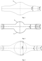
FIG. 1 illustrates a schematic diagram of a preformed tube blank of an automobile axle housing formed through bulging pressing; -
FIG. 2 illustrates a front view of a tube piece formed through pressing of an automobile axle housing formed through bulging pressing; -
FIG. 3 illustrates a top view of a tube piece formed through pressing of an automobile axle housing formed through bulging pressing; -
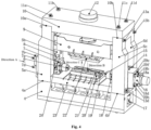
FIG. 4 illustrates a front view of a body structure of a special hydraulic press for bulging pressing forming of an automobile axle housing; -
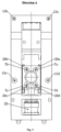
FIG. 5 illustrates a partial schematic structural diagram in a direction A of a front view of a body structure of a special hydraulic press for bulging pressing forming of an automobile axle housing; -
FIG. 6 illustrates a partial schematic structural diagram in a direction B of a front view of a body structure of a special hydraulic press for bulging pressing forming of an automobile axle housing; and -
FIG. 7 illustrates a partial schematic structural diagram in a direction C of a front view of a body structure of a special hydraulic press for bulging pressing forming of an automobile axle housing. - In the accompanying drawings: 1. preformed tube blank, 2. additional front cover of the automobile axle housing, 3. rear cover of the automobile axle housing, 4. lower cross beam, 4a. left stepped surface of the lower cross beam, 4b. right stepped surface of the lower cross beam, 5a. stand column I, 5b. stand column II, 5c. stand column III, 5d. stand column IV, 6. left pressing head, 7. left horizontal slider, 7a. left guide rod I, 7b. left guide rod II, 7c. left guide rod III, 7d. left guide rod IV, 8. left vertical slider, 9. main slider, 10. upper cross beam, 10a. left stepped surface of the upper cross beam, 10b. right stepped surface of the upper cross beam, 11a. vertical pull rod I, 11b. vertical pull rod II, 11c. vertical pull rod III, 11d. vertical pull rod IV, 12. main hydraulic cylinder, 13a. transverse pull rod I, 13b. transverse pull rod II, 13c. transverse pull rod III, 13d. transverse pull rod IV, 14. right vertical slider, 15. right pressing head, 16. right horizontal hydraulic cylinder, 17. right vertical hydraulic cylinder, 18. right horizontal slider, 18a. right guide rod I, 18b. right guide rod II, 18c. right guide rod III, 18d. right guide rod IV, 19. rear die, 20. lower die base, 21. front die, 22. upper die base, 23. worktable, 24. left horizontal hydraulic cylinder, 25. left vertical hydraulic cylinder, 26a, front high-pressure jack, 26b. rear high-pressure jack, 27. lower die, 28. upper die, 29a. guide sleeve I, 29b. guide sleeve II, 29c. guide sleeve III, 29d. guide sleeve IV, 29e. guide sleeve V, 29f. guide sleeve VI, 29g. guide sleeve VII, and 29h. guide sleeve VIII.
-
FIG. 1 shows a preformed tube blank 1 of a large automobile axle housing formed through bulging pressing. The outer diameter de of circular tubes at two ends of the preformed tube blank 1 is equal to Φ170 mm, and the outer diameter d 1 of a circular tube on the inner side of the circular tube at each of the two ends is equal to Φ188 mm.FIG. 2 and FIG. 3 are respectively a front view and a top view of a large automobile axle housing formed through bulging pressing. The height h 0 of a straight tube with a square cross section on the inner side of the circular tube is equal to 158 mm, and the width b 0 is equal to 158 mm. - A special hydraulic press for bulging pressing forming of an automobile axle housing is provided. The hydraulic press is formed by components such as a hydraulic press body, a hydraulic system, an electrical system, a pressing forming die, a pressurization system, and front and rear high-pressure jacks (26a, 26b). The pressing forming die is formed by an
upper die base 22, alower die base 20, anupper die 28, alower die 27, afront die 21, arear die 19, a leftpressing head 6, and a rightpressing head 15. Theupper die base 22 is an inverted-U-shaped structure. Theupper die 28 is mounted in the lower plane of the pedestal of theupper die base 22. Thelower die base 20 is a U-shaped structure. The front and rear high-pressure jacks (26a, 26b) are mounted on inner side walls of the U-shaped structure. Thelower die 27 is mounted in the middle of the upper plane of the pedestal of the U-shaped structure. The front die 21 and the rear die 19 are mounted on front and rear sides thereof. The pressurization system is formed by a low-pressure pressurizer, a high-pressure pressurizer and a high-pressure relief valve. The hydraulic press body includes anupper cross beam 10, alower cross beam 4, four stand columns I, II, III, and IV (5a, 5b, 5c, 5d), four vertical pull rods I, II, III, and IV (11a, 11b, 11c, 11d), four transverse pull rods I, II, III, and IV (13a, 13b, 13c, 13d), amain slider 9, a mainhydraulic cylinder 12, a left vertical slider 8, a rightvertical slider 14, a left verticalhydraulic cylinder 25, a right verticalhydraulic cylinder 17, a left horizontalhydraulic cylinder 24, a right horizontalhydraulic cylinder 16, a lefthorizontal slider 7, a righthorizontal slider 18, aworktable 23, and the like. - The
lower cross beam 4 is an inverted-"T"-shaped case. Theupper cross beam 10 is a "T"-shaped case. The front and rear ends of left and right stepped surfaces (10a, 10b, 4a, 4b) of theupper cross beam 10 and thelower cross beam 4 are respectively supported by the four stand columns I, II, III, and IV (5a, 5b, 5c, 5d) to form a closed frame. Theupper cross beam 10 and thelower cross beam 4 are respectively connected in the vertical direction by the four vertical pull rods I, II, III, and IV (11a, 11b, 11c, and 11d) for balancing external forces applied to theupper cross beam 10 and thelower cross beam 4 in the vertical direction when the hydraulic press is operating. Theupper cross beam 10 and thelower cross beam 4 are respectively connected to upper end parts and lower end parts of the four stand columns I, II, III, and IV (5a, 5b, 5c, 5d) in the horizontal direction by the four transverse pull rods I, II, III, and IV (13a, 13b, 13c, 13d) for balancing external forces applied to the stand columns I, II, III, and IV (5a, 5b, 5c, 5d) in the left-right direction when the hydraulic press is operating. - The main
hydraulic cylinder 12 is mounted upside down on theupper cross beam 10, a lower end of a piston rod of the mainhydraulic cylinder 12 is connected to the top surface of themain slider 9 by a flange, themain slider 9 is connected to theupper die base 22 of the pressing forming die, and the mainhydraulic cylinder 12 drives theupper die base 22 and theupper die 28 to move in the vertical direction. - The left vertical slider 8 is located between the two left stand columns I and II (5a, 5b). The right
vertical slider 14 is located between the two right stand columns III and IV (5c, 5d). The left vertical slider 8 is movable in the vertical direction between the two left stand columns I and II (5a, 5b). The rightvertical slider 14 is movable in the vertical direction between the two right stand columns III and IV (5c, 5d). The bottom surfaces of the left vertical slider 8 and the rightvertical slider 14 are respectively connected to piston rods of the left verticalhydraulic cylinder 25 and the right verticalhydraulic cylinder 17. The left verticalhydraulic cylinder 25 and the right verticalhydraulic cylinder 17 are small hydraulic cylinders. The cylinder bottoms of the left verticalhydraulic cylinder 25 and the right verticalhydraulic cylinder 17 are respectively mounted in the middle of the left steppedsurface 4a and the right steppedsurface 4b of thelower cross beam 4. - The left vertical slider 8 and the right
vertical slider 14 are both case structures. The left horizontalhydraulic cylinder 24 and the right horizontalhydraulic cylinder 16 are respectively mounted in the middle of inner sides of the left vertical slider 8 and the rightvertical slider 14. Guide sleeves I, II, III, and IV (29a, 29b, 29c, 29d) and guide sleeves V, VI, VII, and VIII (29e, 29f, 29g, 29h) are respectively disposed on the upper part and lower part of the left vertical slider 8 and the rightvertical slider 14. Piston rods of the left horizontalhydraulic cylinder 24 and the right horizontalhydraulic cylinder 16 are respectively connected to the lefthorizontal slider 7 and the righthorizontal slider 18 so as to drive theleft pressing head 6 and theright pressing head 15 to move leftwards and rightwards in the horizontal direction. Left guide rods I, II, III, and IV (7a, 7b, 7c, 7d) and right guide rods V, VI, VII, and VIII (18a, 18b, 18c, 18d) are respectively provided at the upper part and lower part of the lefthorizontal slider 7 and the righthorizontal slider 18, and slide in the guide sleeves I, II, III, and IV (29a, 29b, 29c, 29d) and the guide sleeves V, VI, VII, and VIII (29e, 29f, 29g, 29h) respectively disposed in the left vertical slider 8 and the rightvertical slider 14. - The
worktable 23 is mounted in the middle of the upper plane of thelower cross beam 4. Thelower die base 20 of the pressing forming die is mounted on the upper plane of theworktable 23. The front and rear high-pressure jacks (26a, 26b) mounted on the U-shaped inner side walls of thelower die base 20 during pressing forming drive the front die 21 and the rear die 19 to press the preformed tube blank 1 from outside to inside on the upper plane of thelower die base 20. - A forming method of pressing an automobile axle housing by a special hydraulic press for bulging pressing forming of an automobile axle housing includes the following process steps:
- (1) placing a preformed tube blank 1 of an automobile axle housing in a die cavity of a
lower die 27, the tube blank being accurately positioned in the left-right direction and the front-rear direction; - (2) operating left and right horizontal hydraulic cylinders (24, 16) of the hydraulic press so as to drive a left
pressing head 6 and a rightpressing head 15 of a pressing forming die to perform a working feed from outside to inside through left and right horizontal sliders (7, 18), thereby sealing left and right end parts of the preformed tube blank 1; - (3) operating front and rear high-pressure jacks (26a, 26b) so as to drive a
front die 21 and arear die 19 to press the preformed tube blank 1 from outside to inside, until inner side planes of left and right end parts of the front die 21 and the rear die 19 contact outside surfaces at the left and right ends of thelower die 27; - (4) operating a main
hydraulic cylinder 12 of the hydraulic press so as to drive anupper die base 22 through amain slider 9 to move downward and stop until a die cavity of anupper die 28 contacts an upper curved surface of the preformed tube blank 1; - (5) filling the preformed tube blank 1 with an emulsion through the left
pressing head 6 by using a low-pressure pressurizer of a pressurization system, and stopping filling the emulsion when the pressure inside the tube blank reaches a pressure p0 = 12 MPa; - (6) operating the main
hydraulic cylinder 12 of the hydraulic press so as to drive theupper die 28 to press downward the preformed tube blank 1 at a speed v1 equal to 3.5 mm/s, simultaneously driving, by left and right vertical hydraulic cylinders (25, 17), left and right vertical sliders (9, 14) to move downward at a speed v2 , stopping the pressing of theupper die 28 when a distance between two end surfaces of theupper die 28 and two end surfaces of thelower die 27 reaches b0, and keeping the pressure p0 inside the tube blank unchanged in the pressing process; - (7) filling the preformed tube blank 1 with an emulsion through the
right pressing head 15 by using a high-pressure pressurizer of the pressurization system, and stopping filling the emulsion when the pressure inside the tube blank reaches a pressure p1 = 80 MPa; - (8) operating a relief valve of the pressurization system mounted on the
right pressing head 15 so as to unload the high-pressure liquid inside a formed tube piece; - (9) making the left and right horizontal hydraulic cylinders (24, 16) of the hydraulic press return so as to detach the left
pressing head 6 and theright pressing head 15 from the end parts of the tube piece; - (10) driving, by the main
hydraulic cylinder 12 of the hydraulic press, theupper die 28 to return; - (11) making the front and rear high-pressure jacks (26a, 26b) return so as to drive the front die 21 and the rear die 19 to return;
- (12) driving, by the left and right vertical hydraulic cylinders (25, 17), the left and right vertical sliders (9, 14) to move upward so as to drive the
left pressing head 6 and theright pressing head 15 to return to an initial position; and - (13) retrieving the piece, and dumping the liquid in the formed tube piece.
- During the overall pressing forming of the preformed tube blank 1, the main
hydraulic cylinder 12 drives theupper die 28 through themain slider 9 to press downward the middle of the preformed tube blank 1 at a speed v1 , and the left verticalhydraulic cylinder 25 and the right verticalhydraulic cylinder 17 drive theleft pressing head 6 and theright pressing head 15 of the pressing forming die through the left vertical slider 8 and the rightvertical slider 14 to move downward at a speed v2 , wherein the speed v 2 ( v2 = 1.68 mm/s) needs to appropriately match the speed v1 , namely v2 = 0.48v1 , so as to ensure that the left end, the right end and the middle of the preformed tube blank 1 are prevented from bending in the pressing forming process.
Claims (6)
- A special hydraulic press for bulging pressing forming of an automobile axle housing, comprising a hydraulic system, an electrical system, a pressurization system, front and rear high-pressure jacks (26a, 26b), and a pressing forming die, the pressing forming die comprises an upper die (28), a lower die (27), a front die (21), a rear die (19), a left pressing head (6), a right pressing head (15), an upper die base (22) and a lower die base (20), characterized ina lower cross beam (4) is an inverted-"T"-shaped case structure, an upper cross beam (10) is a "T"-shaped case structure, the front and rear ends of left and right stepped surfaces (10a, 10b, 4a, 4b) of the lower cross beam (4) and the upper cross beam (10) are respectively supported by four stand columns I, II, III, and IV (5a, 5b, 5c, 5d) to form a closed frame structure, the upper cross beam (10) and the lower cross beam (4) are respectively connected in the vertical direction by four vertical pull rods I, II, III, and IV (11a, 11b, 11c, and 11d) for balancing external forces applied to the upper cross beam (10) and the lower cross beam (4) in the vertical direction when the hydraulic press is operating, and the upper cross beam (10) and the lower cross beam (4) are respectively connected to upper end parts and lower end parts of the four stand columns I, II, III, and IV (5a, 5b, 5c, 5d) in the horizontal direction by four transverse pull rods I, II, III, and IV (13a, 13b, 13c, 13d) for balancing external forces applied to the four stand columns I, II, III, and IV (5a, 5b, 5c, 5d) in the left-right direction when the hydraulic press is operating;a main hydraulic cylinder (12) is mounted upside down on the upper cross beam (10), a lower end of a piston rod of the main hydraulic cylinder (12) is connected to the top surface of a main slider (9) by a flange, the main slider (9) is connected to the upper die base (22), and the main hydraulic cylinder (12) drives the upper die base (22) and the upper die (28) to move in the vertical direction; whereina left vertical slider (8) is located between the two left stand columns I and II (5a, 5b), a right vertical slider (14) is located between the two right stand columns III and IV (5c, 5d), the left vertical slider (8) is movable in the vertical direction between the two left stand columns I and II (5a, 5b), the right vertical slider (14) is movable in the vertical direction between the two right stand columns III and IV (5c, 5d), the bottom surfaces of the left vertical slider (8) and the right vertical slider (14) are respectively connected to piston rods of a left vertical hydraulic cylinder (25) and a right vertical hydraulic cylinder (17), the left vertical hydraulic cylinder (25) and the right vertical hydraulic cylinder (17) are small hydraulic cylinders, and the cylinder bottoms of the left vertical hydraulic cylinder (25) and the right vertical hydraulic cylinder (17) are respectively mounted in the middle of the left stepped surface (4a) and the right stepped surface (4b) of the lower cross beam (4);the left vertical slider (8) and the right vertical slider (14) are both case structures, a left horizontal hydraulic cylinder (24) and a right horizontal hydraulic cylinder (16) are respectively mounted in the middle of inner sides of the left vertical slider (8) and the right vertical slider (14), and guide sleeves I, II, III, and IV(29a, 29b, 29c, 29d) and guide sleeves V, VI, VII, and VIII (29e, 29f, 29g, 29h) are respectively disposed on the upper part and lower part of the left vertical slider (8) and the right vertical slider (14);piston rods of the left horizontal hydraulic cylinder (24) and the right horizontal hydraulic cylinder (16) are respectively connected to a left horizontal slider (7) and a right horizontal slider (18) so as to drive the left pressing head (6) and the right pressing head (15) to move leftwards and rightwards in the horizontal direction, left guide rods I, II, III, and IV (7a, 7b, 7c, 7d) and right guide rods V, VI, VII, and VIII (18a, 18b, 18c, 18d) are respectively provided at the upper part and lower part of the left horizontal slider (7) and the right horizontal slider (18), and the left guide rods I, II, III, and IV (7a, 7b, 7c, 7d) and the right guide rods V, VI, VII, and VIII (18a, 18b, 18c, 18d) slide in the guide sleeves I, II, III, and IV (29a, 29b, 29c, 29d) and the guide sleeves V, VI, VII, and VIII (29e, 29f, 29g, 29h) are respectively disposed in the left vertical slider (8) and the right vertical slider (14); anda worktable (23) is mounted in the middle of the upper plane of the lower cross beam (4), and the lower die base (20) is mounted in the upper plane of the worktable (23).
- The special hydraulic press for bulging pressing forming of an automobile axle housing according to claim 1, wherein the upper die base (22) is an inverted-U-shaped structure, the upper die (28) is mounted in the lower plane of the pedestal of the upper die base (22), the lower die base (20) is an U-shaped structure, the front and rear high-pressure jacks (26a, 26b) are mounted on inner side walls of the U-shaped structure, the lower die (27) is mounted in the middle of the upper plane of the pedestal of the U-shaped structure, and the front die (21) and the rear die (19) are mounted on front and rear sides of the lower die (27).
- The special hydraulic press for bulging pressing forming of an automobile axle housing according to claim 1 or 2, wherein the front and rear high-pressure jacks (26a, 26b) drive the front die (21) and the rear die (19) to press a preformed tube blank (1) from outside to inside on the upper plane of the lower die base (20) .
- The special hydraulic press for bulging pressing forming of an automobile axle housing according to claim 1, wherein the pressurization system is formed by a low-pressure pressurizer, a high-pressure pressurizer and a high-pressure relief valve.
- A forming method of pressing an automobile axle housing by the special hydraulic press of any of claims 1 to 4 for bulging pressing forming of an automobile axle housing, wherein the forming method comprises the following steps:a. placing a preformed tube blank (1) of an automobile axle housing in a die cavity of a lower die (27), the tube blank (1) being accurately positioned in the left-right direction and the front-rear direction;b. operating left and right horizontal hydraulic cylinders (24, 16) of the hydraulic press so as to drive a left pressing head (6) and a right pressing head (15) to perform a working feed from outside to inside through left and right horizontal sliders (7, 18), thereby sealing left and right end parts of the preformed tube blank (1);c. operating front and rear high-pressure jacks (26a, 26b) so as to drive a front die (21) and a rear die (19) to press the preformed tube blank (1) from outside to inside, until inner side planes of left and right end parts of the front die (21) and the rear die (19) contact outside surfaces at the left and right ends of the lower die (27);d. operating a main hydraulic cylinder (12) of the hydraulic press so as to drive an upper die base (22) through a main slider (9) to move downward and stop until a die cavity of an upper die (28) contacts an upper curved surface of the preformed tube blank (1);e. filling the preformed tube blank (1) with a liquid through a left pressing head (6) by using a low-pressure pressurizer of a pressurization system, and stopping filling the liquid when the pressure inside the tube blank reaches a pressure p0 = 6 MPa to 20 MPa;f. operating the main hydraulic cylinder (12) of the hydraulic press so as to drive the upper die (28) to press downward the preformed tube blank (1) at a speed v 1, simultaneously driving, by left and right vertical hydraulic cylinders (25, 17), left and right vertical sliders (8, 14) to move downward at a speed v 2, stopping the pressing of the upper die (28) when a distance between two end surfaces of the upper die (28) and two end surfaces of the lower die (27) reaches b0, and keeping the pressure p0 inside the tube blank unchanged in the pressing process;g. filling the preformed tube blank (1) with the liquid through a right pressing head (15) by using a high-pressure pressurizer of the pressurization system, and stopping filling the liquid when the pressure inside the tube blank reaches a pressure p1 = 60 MPa to 120 MPa;h. operating a relief valve of the pressurization system mounted on the right pressing head (15) so as to unload the high-pressure liquid inside a formed tube piece;i. making the left and right horizontal hydraulic cylinders (24, 16) of the hydraulic press return so as to detach the left pressing head (6) and the right pressing head (15) from the end parts of the tube piece;j. driving, by the main hydraulic cylinder (12) of the hydraulic press, the upper die (22) to return;k. making the front and rear high-pressure jacks (26a, 26b) return so as to drive the front die (21) and the rear die (19) to return;l. driving, by the left and right vertical hydraulic cylinders (25, 17), the left and right vertical sliders (8, 14) to move upward so as to drive the left pressing head (6) and the right pressing head (15) to return to an initial position; andm. retrieving the piece, and dumping the liquid in the formed tube piece.
- The forming method of pressing an automobile axle housing by a special hydraulic press for bulging pressing forming of an automobile axle housing according to claim 5, wherein during the overall pressing forming of the preformed tube blank (1), the main hydraulic cylinder (12) drives the upper die (28) through the main slider (9) to press downward the middle of the preformed tube blank (1) at a speed v 1, and the left vertical hydraulic cylinder (25) and the right vertical hydraulic cylinder (17) drive the left pressing head (6) and the right pressing head (15) through the left vertical slider (8) and the right vertical slider (14) to move downward at a speed v 2, wherein the speed v 2 needs to appropriately match the speed v 1, namely v 2 = (0.45 to 0.55)vi, so as to ensure that the left end, the right end and the middle of the preformed tube blank are prevented from bending in the pressing forming process.
Applications Claiming Priority (1)
| Application Number | Priority Date | Filing Date | Title |
|---|---|---|---|
| CN201911070787.8A CN110773621B (en) | 2019-11-05 | 2019-11-05 | Special hydraulic press for automobile axle housing bulging forming and press forming method thereof |
Publications (2)
| Publication Number | Publication Date |
|---|---|
| EP3819040A1 EP3819040A1 (en) | 2021-05-12 |
| EP3819040B1 true EP3819040B1 (en) | 2023-03-22 |
Family
ID=69389089
Family Applications (1)
| Application Number | Title | Priority Date | Filing Date |
|---|---|---|---|
| EP20190830.8A Active EP3819040B1 (en) | 2019-11-05 | 2020-08-13 | Special hydraulic press for bulging pressing forming of automobile axle housing and pressing forming method |
Country Status (4)
| Country | Link |
|---|---|
| US (1) | US11801653B2 (en) |
| EP (1) | EP3819040B1 (en) |
| JP (1) | JP6979654B2 (en) |
| CN (1) | CN110773621B (en) |
Families Citing this family (18)
| Publication number | Priority date | Publication date | Assignee | Title |
|---|---|---|---|---|
| CN111389951B (en) | 2020-03-26 | 2020-12-25 | 燕山大学 | Tubular product rolls bloated forming hydraulic press |
| CN111390007B (en) * | 2020-04-01 | 2020-12-11 | 哈尔滨工大海卓智能成形科技有限公司 | Liquid-filled lateral extrusion forming device and method |
| CN111558665B (en) * | 2020-05-13 | 2021-10-29 | 燕山大学 | Forming Technology and Die of Axle Head of Hydraulic Bulging Drive Axle |
| CN113385605B (en) * | 2021-05-10 | 2023-08-04 | 中航西安飞机工业集团股份有限公司 | Liquid filling forming method for large-bow high multi-cavity thin-wall open-pore inner skin |
| CN114192715A (en) * | 2021-12-06 | 2022-03-18 | 河南省中晟智能科技有限公司 | Multidirectional die forging hydraulic press |
| CN114210833A (en) * | 2021-12-10 | 2022-03-22 | 江西江铃底盘股份有限公司 | Automobile rear axle control rod support forming die and machining process thereof |
| CN114713700B (en) * | 2021-12-21 | 2024-04-26 | 倍力汽车轻量化科技(潍坊)有限公司 | Method for integrally forming lightweight driving axle housing through hot air expansion |
| CN114669650A (en) * | 2021-12-21 | 2022-06-28 | 倍力汽车轻量化科技(潍坊)有限公司 | Expansion forming process for driving axle housing |
| CN114247814B (en) * | 2021-12-23 | 2023-12-05 | 湖南顶立科技有限公司 | Extrusion molding device and molding method |
| CN114798815B (en) * | 2022-06-06 | 2023-08-22 | 哈尔滨工业大学(威海) | Part sizing die |
| CN116174652A (en) * | 2022-12-19 | 2023-05-30 | 鹏驰五金制品(昆山)有限公司 | A special processing mold for headless screws |
| CN116197284A (en) * | 2022-12-28 | 2023-06-02 | 河北冀尚医疗器械有限公司 | Forming mechanism for processing walking stick |
| CN116274633B (en) * | 2023-02-27 | 2025-10-17 | 常州鑫邦装饰材料有限公司 | Sheet metal liquid filling forming punching processing equipment |
| CN116329414B (en) * | 2023-04-06 | 2026-02-10 | 燕山大学 | A method for manufacturing heavy truck axle housings |
| CN118950816A (en) * | 2024-08-26 | 2024-11-15 | 燕山大学 | Expansion forming method for automobile axle shell with upper and lower platforms in the middle bridge package |
| CN119794185B (en) * | 2025-03-11 | 2025-07-01 | 山东锣响汽车制造有限公司 | Double angle iron end forming die set with bridge type structure |
| CN120155488B (en) * | 2025-05-19 | 2025-08-01 | 东台市溱标不锈钢有限公司 | Method for high pressure forming of tee pipe fittings |
| CN120515884B (en) * | 2025-07-24 | 2025-11-21 | 沈阳宝驹汽车传动系统有限公司 | High-strength light-weight electric axle housing forming device |
Family Cites Families (8)
| Publication number | Priority date | Publication date | Assignee | Title |
|---|---|---|---|---|
| JP3710486B2 (en) * | 1996-08-26 | 2005-10-26 | コスマ インターナショナル インコーポレイテッド | Hydraulic forming die assembly and method of tube forming without pinching |
| CN1088634C (en) * | 1998-10-28 | 2002-08-07 | 辽源市重型机器厂 | Vehicle rear axle shell hydraulic expanding-forming process |
| JP3514159B2 (en) * | 1999-03-23 | 2004-03-31 | 住友金属工業株式会社 | Hydraulic bulging apparatus for metal pipe and method for manufacturing metal pipe |
| US7024897B2 (en) * | 1999-09-24 | 2006-04-11 | Hot Metal Gas Forming Intellectual Property, Inc. | Method of forming a tubular blank into a structural component and die therefor |
| US20120047979A1 (en) * | 2010-08-25 | 2012-03-01 | Schuler Inc. | Hydroforming die assembly and method for deforming a tube |
| CN102172704B (en) * | 2011-01-21 | 2012-11-07 | 西安交通大学 | Large-tonnage pipe internal high-pressure forming device |
| CN104085128B (en) * | 2014-06-30 | 2015-11-25 | 南京迪威尔高端制造股份有限公司 | Combined bidirectional prestressing force framework for support |
| CN105728539B (en) * | 2016-05-11 | 2018-02-06 | 燕山大学 | The compressing mould of big-and-middle-sized automobile axle housing pipe fitting topping up |
-
2019
- 2019-11-05 CN CN201911070787.8A patent/CN110773621B/en active Active
-
2020
- 2020-08-13 EP EP20190830.8A patent/EP3819040B1/en active Active
- 2020-08-27 JP JP2020143930A patent/JP6979654B2/en active Active
- 2020-09-07 US US17/013,777 patent/US11801653B2/en active Active
Also Published As
| Publication number | Publication date |
|---|---|
| JP6979654B2 (en) | 2021-12-15 |
| EP3819040A1 (en) | 2021-05-12 |
| CN110773621B (en) | 2021-06-01 |
| US11801653B2 (en) | 2023-10-31 |
| JP2021074774A (en) | 2021-05-20 |
| US20210129472A1 (en) | 2021-05-06 |
| CN110773621A (en) | 2020-02-11 |
Similar Documents
| Publication | Publication Date | Title |
|---|---|---|
| US11801653B2 (en) | Special hydraulic press for bulging pressing forming of automobile axle housing and pressing forming method | |
| CN110935779B (en) | Pipe liquid-filling multidirectional extrusion forming device and method | |
| CN105728539B (en) | The compressing mould of big-and-middle-sized automobile axle housing pipe fitting topping up | |
| CA2498825C (en) | Mechanical press apparatus | |
| CN103084460B (en) | Monolithic molding method of light duty truck weldless axle case | |
| CN103252404B (en) | The integral forming method of heavy truck no-welding-seam axle housing | |
| EP1638713A1 (en) | Hydroforming apparatus with stacked dies | |
| CN209349444U (en) | A kind of big variable diameter automobile half shaft tube hot-extrusion die | |
| US20030074948A1 (en) | Machine press | |
| CN101927299A (en) | Mechanical pipe fitting bulging device | |
| CN107639144A (en) | A kind of Drive axle housing hydraulic forming method using high intensity welded tube and without annealing | |
| CN206392667U (en) | A kind of high-pressure forming equipment | |
| US5463892A (en) | Hydraulic press | |
| CN101637792B (en) | Punch forming device of guide grooves of energy-absorbing box of automobile anti-collision rod | |
| CN212019277U (en) | Multidirectional die forging equipment | |
| CN207668267U (en) | A kind of Drive axle housing hydraulic bulging device | |
| CN114670479A (en) | High-pressure quick long-stroke hydraulic machine | |
| CN201455082U (en) | Device for molding guiding groove of energy-absorbing box in bumper of automobile | |
| CN110369594A (en) | A kind of manufacturing process manufacturing banjo type housing part | |
| CN201714739U (en) | Composite oil cylinder | |
| CN110899411B (en) | Bending forming system and method for bent arm knuckle | |
| CN111390007B (en) | Liquid-filled lateral extrusion forming device and method | |
| CN220311512U (en) | Axle housing tube blank mould for plate forming | |
| CN215544176U (en) | Integral type hydraulic pressure tapered wedge device | |
| CN205763387U (en) | A kind of axle housing shaping mould |
Legal Events
| Date | Code | Title | Description |
|---|---|---|---|
| PUAI | Public reference made under article 153(3) epc to a published international application that has entered the european phase |
Free format text: ORIGINAL CODE: 0009012 |
|
| STAA | Information on the status of an ep patent application or granted ep patent |
Free format text: STATUS: REQUEST FOR EXAMINATION WAS MADE |
|
| 17P | Request for examination filed |
Effective date: 20200813 |
|
| AK | Designated contracting states |
Kind code of ref document: A1 Designated state(s): AL AT BE BG CH CY CZ DE DK EE ES FI FR GB GR HR HU IE IS IT LI LT LU LV MC MK MT NL NO PL PT RO RS SE SI SK SM TR |
|
| GRAP | Despatch of communication of intention to grant a patent |
Free format text: ORIGINAL CODE: EPIDOSNIGR1 |
|
| STAA | Information on the status of an ep patent application or granted ep patent |
Free format text: STATUS: GRANT OF PATENT IS INTENDED |
|
| INTG | Intention to grant announced |
Effective date: 20221122 |
|
| GRAS | Grant fee paid |
Free format text: ORIGINAL CODE: EPIDOSNIGR3 |
|
| GRAA | (expected) grant |
Free format text: ORIGINAL CODE: 0009210 |
|
| STAA | Information on the status of an ep patent application or granted ep patent |
Free format text: STATUS: THE PATENT HAS BEEN GRANTED |
|
| AK | Designated contracting states |
Kind code of ref document: B1 Designated state(s): AL AT BE BG CH CY CZ DE DK EE ES FI FR GB GR HR HU IE IS IT LI LT LU LV MC MK MT NL NO PL PT RO RS SE SI SK SM TR |
|
| REG | Reference to a national code |
Ref country code: GB Ref legal event code: FG4D |
|
| REG | Reference to a national code |
Ref country code: CH Ref legal event code: EP |
|
| REG | Reference to a national code |
Ref country code: DE Ref legal event code: R096 Ref document number: 602020008983 Country of ref document: DE |
|
| REG | Reference to a national code |
Ref country code: IE Ref legal event code: FG4D |
|
| REG | Reference to a national code |
Ref country code: AT Ref legal event code: REF Ref document number: 1554970 Country of ref document: AT Kind code of ref document: T Effective date: 20230415 |
|
| REG | Reference to a national code |
Ref country code: SE Ref legal event code: TRGR |
|
| REG | Reference to a national code |
Ref country code: LT Ref legal event code: MG9D |
|
| REG | Reference to a national code |
Ref country code: NL Ref legal event code: MP Effective date: 20230322 |
|
| PG25 | Lapsed in a contracting state [announced via postgrant information from national office to epo] |
Ref country code: RS Free format text: LAPSE BECAUSE OF FAILURE TO SUBMIT A TRANSLATION OF THE DESCRIPTION OR TO PAY THE FEE WITHIN THE PRESCRIBED TIME-LIMIT Effective date: 20230322 Ref country code: NO Free format text: LAPSE BECAUSE OF FAILURE TO SUBMIT A TRANSLATION OF THE DESCRIPTION OR TO PAY THE FEE WITHIN THE PRESCRIBED TIME-LIMIT Effective date: 20230622 Ref country code: LV Free format text: LAPSE BECAUSE OF FAILURE TO SUBMIT A TRANSLATION OF THE DESCRIPTION OR TO PAY THE FEE WITHIN THE PRESCRIBED TIME-LIMIT Effective date: 20230322 Ref country code: LT Free format text: LAPSE BECAUSE OF FAILURE TO SUBMIT A TRANSLATION OF THE DESCRIPTION OR TO PAY THE FEE WITHIN THE PRESCRIBED TIME-LIMIT Effective date: 20230322 Ref country code: HR Free format text: LAPSE BECAUSE OF FAILURE TO SUBMIT A TRANSLATION OF THE DESCRIPTION OR TO PAY THE FEE WITHIN THE PRESCRIBED TIME-LIMIT Effective date: 20230322 |
|
| REG | Reference to a national code |
Ref country code: AT Ref legal event code: MK05 Ref document number: 1554970 Country of ref document: AT Kind code of ref document: T Effective date: 20230322 |
|
| PG25 | Lapsed in a contracting state [announced via postgrant information from national office to epo] |
Ref country code: NL Free format text: LAPSE BECAUSE OF FAILURE TO SUBMIT A TRANSLATION OF THE DESCRIPTION OR TO PAY THE FEE WITHIN THE PRESCRIBED TIME-LIMIT Effective date: 20230322 Ref country code: GR Free format text: LAPSE BECAUSE OF FAILURE TO SUBMIT A TRANSLATION OF THE DESCRIPTION OR TO PAY THE FEE WITHIN THE PRESCRIBED TIME-LIMIT Effective date: 20230623 Ref country code: FI Free format text: LAPSE BECAUSE OF FAILURE TO SUBMIT A TRANSLATION OF THE DESCRIPTION OR TO PAY THE FEE WITHIN THE PRESCRIBED TIME-LIMIT Effective date: 20230322 |
|
| PG25 | Lapsed in a contracting state [announced via postgrant information from national office to epo] |
Ref country code: SM Free format text: LAPSE BECAUSE OF FAILURE TO SUBMIT A TRANSLATION OF THE DESCRIPTION OR TO PAY THE FEE WITHIN THE PRESCRIBED TIME-LIMIT Effective date: 20230322 Ref country code: RO Free format text: LAPSE BECAUSE OF FAILURE TO SUBMIT A TRANSLATION OF THE DESCRIPTION OR TO PAY THE FEE WITHIN THE PRESCRIBED TIME-LIMIT Effective date: 20230322 Ref country code: PT Free format text: LAPSE BECAUSE OF FAILURE TO SUBMIT A TRANSLATION OF THE DESCRIPTION OR TO PAY THE FEE WITHIN THE PRESCRIBED TIME-LIMIT Effective date: 20230724 Ref country code: ES Free format text: LAPSE BECAUSE OF FAILURE TO SUBMIT A TRANSLATION OF THE DESCRIPTION OR TO PAY THE FEE WITHIN THE PRESCRIBED TIME-LIMIT Effective date: 20230322 Ref country code: EE Free format text: LAPSE BECAUSE OF FAILURE TO SUBMIT A TRANSLATION OF THE DESCRIPTION OR TO PAY THE FEE WITHIN THE PRESCRIBED TIME-LIMIT Effective date: 20230322 Ref country code: AT Free format text: LAPSE BECAUSE OF FAILURE TO SUBMIT A TRANSLATION OF THE DESCRIPTION OR TO PAY THE FEE WITHIN THE PRESCRIBED TIME-LIMIT Effective date: 20230322 |
|
| PG25 | Lapsed in a contracting state [announced via postgrant information from national office to epo] |
Ref country code: SK Free format text: LAPSE BECAUSE OF FAILURE TO SUBMIT A TRANSLATION OF THE DESCRIPTION OR TO PAY THE FEE WITHIN THE PRESCRIBED TIME-LIMIT Effective date: 20230322 Ref country code: PL Free format text: LAPSE BECAUSE OF FAILURE TO SUBMIT A TRANSLATION OF THE DESCRIPTION OR TO PAY THE FEE WITHIN THE PRESCRIBED TIME-LIMIT Effective date: 20230322 Ref country code: IS Free format text: LAPSE BECAUSE OF FAILURE TO SUBMIT A TRANSLATION OF THE DESCRIPTION OR TO PAY THE FEE WITHIN THE PRESCRIBED TIME-LIMIT Effective date: 20230722 |
|
| REG | Reference to a national code |
Ref country code: DE Ref legal event code: R097 Ref document number: 602020008983 Country of ref document: DE |
|
| PLBE | No opposition filed within time limit |
Free format text: ORIGINAL CODE: 0009261 |
|
| STAA | Information on the status of an ep patent application or granted ep patent |
Free format text: STATUS: NO OPPOSITION FILED WITHIN TIME LIMIT |
|
| PG25 | Lapsed in a contracting state [announced via postgrant information from national office to epo] |
Ref country code: SI Free format text: LAPSE BECAUSE OF FAILURE TO SUBMIT A TRANSLATION OF THE DESCRIPTION OR TO PAY THE FEE WITHIN THE PRESCRIBED TIME-LIMIT Effective date: 20230322 Ref country code: DK Free format text: LAPSE BECAUSE OF FAILURE TO SUBMIT A TRANSLATION OF THE DESCRIPTION OR TO PAY THE FEE WITHIN THE PRESCRIBED TIME-LIMIT Effective date: 20230322 Ref country code: CZ Free format text: LAPSE BECAUSE OF FAILURE TO SUBMIT A TRANSLATION OF THE DESCRIPTION OR TO PAY THE FEE WITHIN THE PRESCRIBED TIME-LIMIT Effective date: 20230322 |
|
| 26N | No opposition filed |
Effective date: 20240102 |
|
| PG25 | Lapsed in a contracting state [announced via postgrant information from national office to epo] |
Ref country code: MC Free format text: LAPSE BECAUSE OF FAILURE TO SUBMIT A TRANSLATION OF THE DESCRIPTION OR TO PAY THE FEE WITHIN THE PRESCRIBED TIME-LIMIT Effective date: 20230322 |
|
| REG | Reference to a national code |
Ref country code: CH Ref legal event code: PL |
|
| PG25 | Lapsed in a contracting state [announced via postgrant information from national office to epo] |
Ref country code: MC Free format text: LAPSE BECAUSE OF FAILURE TO SUBMIT A TRANSLATION OF THE DESCRIPTION OR TO PAY THE FEE WITHIN THE PRESCRIBED TIME-LIMIT Effective date: 20230322 |
|
| PG25 | Lapsed in a contracting state [announced via postgrant information from national office to epo] |
Ref country code: LU Free format text: LAPSE BECAUSE OF NON-PAYMENT OF DUE FEES Effective date: 20230813 |
|
| PG25 | Lapsed in a contracting state [announced via postgrant information from national office to epo] |
Ref country code: LU Free format text: LAPSE BECAUSE OF NON-PAYMENT OF DUE FEES Effective date: 20230813 Ref country code: CH Free format text: LAPSE BECAUSE OF NON-PAYMENT OF DUE FEES Effective date: 20230831 |
|
| REG | Reference to a national code |
Ref country code: BE Ref legal event code: MM Effective date: 20230831 |
|
| REG | Reference to a national code |
Ref country code: IE Ref legal event code: MM4A |
|
| PG25 | Lapsed in a contracting state [announced via postgrant information from national office to epo] |
Ref country code: IT Free format text: LAPSE BECAUSE OF FAILURE TO SUBMIT A TRANSLATION OF THE DESCRIPTION OR TO PAY THE FEE WITHIN THE PRESCRIBED TIME-LIMIT Effective date: 20230322 |
|
| PG25 | Lapsed in a contracting state [announced via postgrant information from national office to epo] |
Ref country code: IE Free format text: LAPSE BECAUSE OF NON-PAYMENT OF DUE FEES Effective date: 20230813 |
|
| PG25 | Lapsed in a contracting state [announced via postgrant information from national office to epo] |
Ref country code: IE Free format text: LAPSE BECAUSE OF NON-PAYMENT OF DUE FEES Effective date: 20230813 Ref country code: FR Free format text: LAPSE BECAUSE OF NON-PAYMENT OF DUE FEES Effective date: 20230831 |
|
| PG25 | Lapsed in a contracting state [announced via postgrant information from national office to epo] |
Ref country code: BE Free format text: LAPSE BECAUSE OF NON-PAYMENT OF DUE FEES Effective date: 20230831 |
|
| PG25 | Lapsed in a contracting state [announced via postgrant information from national office to epo] |
Ref country code: BG Free format text: LAPSE BECAUSE OF FAILURE TO SUBMIT A TRANSLATION OF THE DESCRIPTION OR TO PAY THE FEE WITHIN THE PRESCRIBED TIME-LIMIT Effective date: 20230322 |
|
| PG25 | Lapsed in a contracting state [announced via postgrant information from national office to epo] |
Ref country code: BG Free format text: LAPSE BECAUSE OF FAILURE TO SUBMIT A TRANSLATION OF THE DESCRIPTION OR TO PAY THE FEE WITHIN THE PRESCRIBED TIME-LIMIT Effective date: 20230322 |
|
| GBPC | Gb: european patent ceased through non-payment of renewal fee |
Effective date: 20240813 |
|
| PG25 | Lapsed in a contracting state [announced via postgrant information from national office to epo] |
Ref country code: GB Free format text: LAPSE BECAUSE OF NON-PAYMENT OF DUE FEES Effective date: 20240813 |
|
| PG25 | Lapsed in a contracting state [announced via postgrant information from national office to epo] |
Ref country code: CY Free format text: LAPSE BECAUSE OF FAILURE TO SUBMIT A TRANSLATION OF THE DESCRIPTION OR TO PAY THE FEE WITHIN THE PRESCRIBED TIME-LIMIT; INVALID AB INITIO Effective date: 20200813 |
|
| PG25 | Lapsed in a contracting state [announced via postgrant information from national office to epo] |
Ref country code: HU Free format text: LAPSE BECAUSE OF FAILURE TO SUBMIT A TRANSLATION OF THE DESCRIPTION OR TO PAY THE FEE WITHIN THE PRESCRIBED TIME-LIMIT; INVALID AB INITIO Effective date: 20200813 |
|
| PGFP | Annual fee paid to national office [announced via postgrant information from national office to epo] |
Ref country code: DE Payment date: 20250812 Year of fee payment: 6 |
|
| PGFP | Annual fee paid to national office [announced via postgrant information from national office to epo] |
Ref country code: SE Payment date: 20250826 Year of fee payment: 6 |
|
| PG25 | Lapsed in a contracting state [announced via postgrant information from national office to epo] |
Ref country code: TR Free format text: LAPSE BECAUSE OF FAILURE TO SUBMIT A TRANSLATION OF THE DESCRIPTION OR TO PAY THE FEE WITHIN THE PRESCRIBED TIME-LIMIT Effective date: 20230322 |
|
| REG | Reference to a national code |
Ref country code: DE Ref legal event code: R081 Ref document number: 602020008983 Country of ref document: DE Owner name: QINHUANGDAO TONGQIAO TECHNOLOGY CO., LTD., QIN, CN Free format text: FORMER OWNERS: QINHUANGDAO TONGQIAO TECHNOLOGY CO., LTD., QINHUANGDAO, HEBEI, CN; YANSHAN UNIVERSITY, QINHUANGDAO, HEBEI, CN |