EP3819001A1 - Pneumatic connector apparatus and method - Google Patents
Pneumatic connector apparatus and method Download PDFInfo
- Publication number
- EP3819001A1 EP3819001A1 EP20205983.8A EP20205983A EP3819001A1 EP 3819001 A1 EP3819001 A1 EP 3819001A1 EP 20205983 A EP20205983 A EP 20205983A EP 3819001 A1 EP3819001 A1 EP 3819001A1
- Authority
- EP
- European Patent Office
- Prior art keywords
- barbed
- receiver disk
- respiratory
- disk
- conduits
- Prior art date
- Legal status (The legal status is an assumption and is not a legal conclusion. Google has not performed a legal analysis and makes no representation as to the accuracy of the status listed.)
- Granted
Links
Images


Classifications
-
- A—HUMAN NECESSITIES
- A61—MEDICAL OR VETERINARY SCIENCE; HYGIENE
- A61M—DEVICES FOR INTRODUCING MEDIA INTO, OR ONTO, THE BODY; DEVICES FOR TRANSDUCING BODY MEDIA OR FOR TAKING MEDIA FROM THE BODY; DEVICES FOR PRODUCING OR ENDING SLEEP OR STUPOR
- A61M16/00—Devices for influencing the respiratory system of patients by gas treatment, e.g. ventilators; Tracheal tubes
- A61M16/08—Bellows; Connecting tubes ; Water traps; Patient circuits
- A61M16/0816—Joints or connectors
-
- A—HUMAN NECESSITIES
- A61—MEDICAL OR VETERINARY SCIENCE; HYGIENE
- A61M—DEVICES FOR INTRODUCING MEDIA INTO, OR ONTO, THE BODY; DEVICES FOR TRANSDUCING BODY MEDIA OR FOR TAKING MEDIA FROM THE BODY; DEVICES FOR PRODUCING OR ENDING SLEEP OR STUPOR
- A61M16/00—Devices for influencing the respiratory system of patients by gas treatment, e.g. ventilators; Tracheal tubes
- A61M16/021—Devices for influencing the respiratory system of patients by gas treatment, e.g. ventilators; Tracheal tubes operated by electrical means
- A61M16/022—Control means therefor
-
- A—HUMAN NECESSITIES
- A61—MEDICAL OR VETERINARY SCIENCE; HYGIENE
- A61M—DEVICES FOR INTRODUCING MEDIA INTO, OR ONTO, THE BODY; DEVICES FOR TRANSDUCING BODY MEDIA OR FOR TAKING MEDIA FROM THE BODY; DEVICES FOR PRODUCING OR ENDING SLEEP OR STUPOR
- A61M16/00—Devices for influencing the respiratory system of patients by gas treatment, e.g. ventilators; Tracheal tubes
- A61M16/08—Bellows; Connecting tubes ; Water traps; Patient circuits
- A61M16/0875—Connecting tubes
-
- F—MECHANICAL ENGINEERING; LIGHTING; HEATING; WEAPONS; BLASTING
- F16—ENGINEERING ELEMENTS AND UNITS; GENERAL MEASURES FOR PRODUCING AND MAINTAINING EFFECTIVE FUNCTIONING OF MACHINES OR INSTALLATIONS; THERMAL INSULATION IN GENERAL
- F16L—PIPES; JOINTS OR FITTINGS FOR PIPES; SUPPORTS FOR PIPES, CABLES OR PROTECTIVE TUBING; MEANS FOR THERMAL INSULATION IN GENERAL
- F16L37/00—Couplings of the quick-acting type
- F16L37/56—Couplings of the quick-acting type for double-walled or multi-channel pipes or pipe assemblies
-
- F—MECHANICAL ENGINEERING; LIGHTING; HEATING; WEAPONS; BLASTING
- F16—ENGINEERING ELEMENTS AND UNITS; GENERAL MEASURES FOR PRODUCING AND MAINTAINING EFFECTIVE FUNCTIONING OF MACHINES OR INSTALLATIONS; THERMAL INSULATION IN GENERAL
- F16L—PIPES; JOINTS OR FITTINGS FOR PIPES; SUPPORTS FOR PIPES, CABLES OR PROTECTIVE TUBING; MEANS FOR THERMAL INSULATION IN GENERAL
- F16L37/00—Couplings of the quick-acting type
- F16L37/60—Couplings of the quick-acting type with plug and fixed wall housing
-
- A—HUMAN NECESSITIES
- A61—MEDICAL OR VETERINARY SCIENCE; HYGIENE
- A61M—DEVICES FOR INTRODUCING MEDIA INTO, OR ONTO, THE BODY; DEVICES FOR TRANSDUCING BODY MEDIA OR FOR TAKING MEDIA FROM THE BODY; DEVICES FOR PRODUCING OR ENDING SLEEP OR STUPOR
- A61M2202/00—Special media to be introduced, removed or treated
- A61M2202/02—Gases
- A61M2202/0208—Oxygen
-
- A—HUMAN NECESSITIES
- A61—MEDICAL OR VETERINARY SCIENCE; HYGIENE
- A61M—DEVICES FOR INTRODUCING MEDIA INTO, OR ONTO, THE BODY; DEVICES FOR TRANSDUCING BODY MEDIA OR FOR TAKING MEDIA FROM THE BODY; DEVICES FOR PRODUCING OR ENDING SLEEP OR STUPOR
- A61M2205/00—General characteristics of the apparatus
- A61M2205/02—General characteristics of the apparatus characterised by a particular materials
-
- A—HUMAN NECESSITIES
- A61—MEDICAL OR VETERINARY SCIENCE; HYGIENE
- A61M—DEVICES FOR INTRODUCING MEDIA INTO, OR ONTO, THE BODY; DEVICES FOR TRANSDUCING BODY MEDIA OR FOR TAKING MEDIA FROM THE BODY; DEVICES FOR PRODUCING OR ENDING SLEEP OR STUPOR
- A61M2205/00—General characteristics of the apparatus
- A61M2205/02—General characteristics of the apparatus characterised by a particular materials
- A61M2205/025—Materials providing resistance against corrosion
-
- A—HUMAN NECESSITIES
- A61—MEDICAL OR VETERINARY SCIENCE; HYGIENE
- A61M—DEVICES FOR INTRODUCING MEDIA INTO, OR ONTO, THE BODY; DEVICES FOR TRANSDUCING BODY MEDIA OR FOR TAKING MEDIA FROM THE BODY; DEVICES FOR PRODUCING OR ENDING SLEEP OR STUPOR
- A61M39/00—Tubes, tube connectors, tube couplings, valves, access sites or the like, specially adapted for medical use
- A61M39/10—Tube connectors or tube couplings
- A61M39/105—Multi-channel connectors or couplings, e.g. for connecting multi-lumen tubes
Definitions
- the present disclosure relates to a multiple conduit connector that may be used for simultaneously interconnecting multiple tubes. More particularly, the present disclosure relates to a multiple conduit connector including a quick action lock/release mechanism having a self-alignment feature enhancing proper interconnection for each of the individual tubes.
- Multiple tube connectors typically employ at least two coupling parts having paths for the flow of gas or liquid therethrough which are suitably connected to the ends of the tubing and then interconnected to one another so as to provide gas or liquid communication between the two sets of tubing. Oftentimes, one of the coupling parts is mounted on a panel.
- Threaded fasteners sometimes require a substantial amount of time to be threaded to connect multiple tube connectors.
- threaded fasteners that are threaded at an incorrect angle may become cross-threaded and damaged.
- threaded fasteners may be connected incorrectly, such that the two coupling parts connect the wrong tubes to each other.
- the threaded fasteners need to be properly tightened.
- the degree to which the coupling parts are tightened may vary substantially.
- Some multiple tube connectors are made from plastics materials and are injection molded to form a one piece multiple tube connector. These types of multiple tube connectors may break during use leaving the device unusable until a new multiple tube connector is installed to replace the broken multiple tube connector.
- a multi-port connector for a respiratory therapy device includes a connector base, a receiver disk coupled to the connector base, and a plurality of barbed conduits.
- the receiver disk being formed to include a plurality of apertures with a first diameter, each of the plurality of barbed conduits including a retainer section with a second diameter that is greater than the first diameter so that each barbed conduit forms a friction-interference fit between the receiver disk and each retainer section.
- the receiver disk is coupled to the connector base for pivotable movement relative to the connector base about an axis between an unlocked orientation and a locked orientation and an adaptor is configured to be coupled to the plurality of barbed conduits when the receiver disk is in the unlocked orientation.
- the connector base includes a body plate with a central opening sized to receive the receiver disk and first and second retainer tabs coupled to the body plate on opposite sides of the central opening, the first and second retainer tabs providing first and second slots between the body plate and first and second retainer tabs.
- the adaptor includes an adaptor body and first and second lock tabs coupled to opposite sides of the adaptor body and that extend radially outward from the adaptor body in opposite directions, the first and second lock tabs being sized to extend into the first and second slots when the adaptor is coupled to the plurality of barbed conduits and the receiver disk is subsequently rotated to the locked orientation.
- the receiver disk and the plurality of barbed conduits comprise metallic materials. In some embodiments of the first aspect, the receiver disk and the plurality of barbed conduits comprise stainless steel.
- the second diameter is sized selectively so that the friction-interference fit is able to withstand a predetermined pull force.
- the predetermined pull force is at least 200 Newtons.
- the second diameter is about 0.34% larger than the first diameter to provide the friction-interference fit.
- the receiver disk is formed to include a first detent notch and a second detent notch spaced apart circumferentially from the first detent notch by about 45 degrees about the axis.
- the first detent notch and the second detent notch are formed in a back side of the receiver disk and extend inwardly from an outer edge of the receiver disk toward the axis.
- the connector base includes a detent tab that engages the first detent notch when the receiver disk is in the unlocked orientation and engages the second detent notch when the receiver disk is in the locked orientation.
- each of the plurality of barbed conduits includes a first spot weld and a second spot weld each located at interface points between the receiver disk and the retainer section along a back side of the receiver disk.
- the first spot weld and the second spot weld are located on opposite sides of each barbed conduit.
- each of the plurality of barbed conduits further includes a slot section directly adjacent to the retainer section, and each slot section is sized to receive a clip that engages a back side of the receiver disk and an edge of the slot section.
- the receiver disk is formed to include a guide slot with a first rectangular portion that extends along a first axis and second portion opening into the first portion that extends along a second axis that is perpendicular to the first axis.
- the adaptor includes a guide post with a shape that matches the guide slot.
- a respiratory therapy device includes a respiratory control unit, a respiratory circuit, and a multi-port connector.
- the respiratory control unit is configured to provide at least one respiratory therapy for a user.
- the respiratory circuit is coupled to the respiratory control unit to deliver the respiratory therapy to the user and includes an adaptor configured to be coupled to the connector base.
- the multi-port connector interconnecting the respiratory circuit to the respiratory control unit.
- the multi-port connector includes a connector base coupled to the respiratory control unit, a receiver disk coupled to the connector base, and a plurality of barbed conduits coupled to the receiver disk.
- the receiver disk is formed to include a plurality of apertures with a first diameter.
- Each of the plurality of barbed conduits include a retainer section with a second diameter greater than the first diameter so that each barbed conduit forms a friction-interference fit between the receiver disk and the retainer section.
- the receiver disk is coupled to the connector base for pivotable movement relative to the connector base about an axis between an unlocked orientation and a locked orientation and the adaptor is configured to be coupled to the plurality of barbed conduits when the receiver disk is in the unlocked orientation.
- the connector base includes a body plate with a central opening sized to receive the receiver disk and first and second retainer tabs coupled to the body plate on opposite sides of the central opening, the first and second retainer tabs providing first and second slots between the body plate and first and second retainer tabs.
- the adaptor includes an adaptor body and first and second lock tabs coupled to opposite sides of the adaptor body and that extend radially outward from the adaptor body in opposite directions, the first and second lock tabs being sized to extend into the first and second slots when the adaptor is coupled to the plurality of barbed conduits and the receiver disk is subsequently rotated to the locked orientation.
- the receiver disk and the plurality of barbed conduits comprise metallic materials. In some embodiments of the second aspect, the receiver disk and the plurality of barbed conduits comprise stainless steel.
- the second diameter is sized selectively so that the friction-interference fit is able to withstand a predetermined pull force.
- the predetermined pull force is at least 200 Newtons.
- the second diameter is about 0.34% larger than the first diameter to provide the friction-interference fit.
- the receiver disk is formed to include a first detent notch and a second detent notch spaced apart circumferentially from the first detent notch by about 45 degrees about the axis.
- the first detent notch and the second detent notch are formed in a back side of the receiver disk and extend inwardly from an outer edge of the receiver disk toward the axis.
- the connector base includes a detent tab that engages the first detent notch when the receiver disk is in the unlocked orientation and engages the second detent notch when the receiver disk is in the locked orientation.
- each of the plurality of barbed conduits includes a first spot weld and a second spot weld each located at interface points between the receiver disk and the retainer section along a back side of the receiver disk.
- the first spot weld and the second spot weld are located on opposite sides of each barbed conduit.
- each of the plurality of barbed conduits further includes a slot section directly adjacent to the retainer section, and each slot section is sized to receive a clip that engages a back side of the receiver disk and an edge of the slot section.
- the receiver disk is formed to include a guide slot with a first rectangular portion that extends along a first axis and second portion opening into the first portion that extends along a second axis that is perpendicular to the first axis.
- the adaptor includes a guide post with a shape that matches the guide slot.
- a method of forming a quick disconnect multi-port connector for a respiratory therapy device includes providing a disk made from metallic materials. The method may further include machining a plurality of apertures through the disk. The method may further include providing a plurality of tubes made from metallic materials. The method may further include machining each of the tubes to include an outer surface with a plurality of barb sections and an inner surface defining a fluid passageway that extends through each of the tubes, one of the barb sections forming a retainer section with an outer diameter that is greater than each of the apertures formed in the disk.
- the method may further include inserting one of the plurality of tubes into each aperture formed in the disk, the retainer section of each of the plurality of tubes interfacing with a wall defining each aperture to form a friction-interference fit between the disk and the retainer section to couple each tube to the disk.
- the step of spot welding each of the tubes to the disk at an interface point between the retainer section and the disk is
- each tube has a first spot weld on a first side of the tube at the interface point between the retainer section and the disk and a second spot weld on a second side of the tube opposite the first side at the interface point between the retainer section and the disk.
- the step of machining each of the tubes further includes machining a slot section into each tube adjacent to each retainer section and the step of inserting further includes inserting a clip into the slot section between the disk and an edge of the slot section.
- the step of machining the apertures in the disk further includes polishing the walls defining each of the apertures to remove sharp edges.
- the metallic materials of the disk and the plurality of tubes comprise stainless steel.
- a respiratory therapy device 10 is shown and is used by a respiratory therapist to deliver one or more respiratory therapies to a patient.
- the respiratory therapy device 10 includes respiratory control unit 12, a respiratory circuit 14, and a multi-port connector 16.
- the respiratory control unit 12 is configured to provide the respiratory therapy.
- the respiratory therapy may include delivering a medicated aerosol or applying a composite therapy involving alternation between continuous high frequency oscillation (CHFO) therapy and continuous positive expiratory pressure (CPEP) therapy each in conjunction with the aerosol delivery.
- the respiratory circuit 14 is configured to deliver the respiratory therapy to the patient from the respiratory control unit 12.
- An example of a suitable respiratory control unit 12 and associated respiratory circuit 14 is shown and described in U.S. Patent No. 9,675,775, issued on June 13, 2017 , which is expressly incorporated by reference herein in its entirety for the purpose of describing a suitable respiratory control unit 12 and respiratory circuit 14.
- the respiratory control unit 12 includes a housing 18 that contains associated control unit equipment (not shown) for providing the respiratory therapy.
- the respiratory control unit 12 further includes a plurality of visible components on an outer surface 24 of the housing 18.
- the visible components include a pressure manometer 26, an intensity switch 28 for selecting between a higher and lower percussive intensity, a mode selector 30 for selecting between modes, an oxygen gas connector 32, and a flow adjustor 34 for regulating an amount of oxygen flow when in the CPEP mode.
- the oxygen gas connector 32 is configured to be coupled to an external gas source such as a canister or a port on a wall in a healthcare facility.
- the respiratory circuit 14 includes an adaptor 36 that is configured to be coupled removably with the multi-port connector 16 as show in Fig. 1 .
- the respiratory circuit 14 further includes a handset 38, a nebulizer unit 40, and a plurality of tubular conduits 42 interconnecting the adaptor 36 to the handset 38 and nebulizer unit 40.
- the handset 38 includes a mouthpiece 44 that the patient uses to receive the respiratory therapy when the respiratory circuit 14 is coupled to the respiratory control unit 12 and the respiratory control unit 12 is on.
- the nebulizer unit 40 is configured to convert a liquid medication into a mist so that the patient may breathe the medication into their lungs for the treatment of various conditions. However, in some embodiments, the respiratory circuit 14 may not include the nebulizer unit 40.
- the plurality of conduits 42 are configured to transfer fluid, i.e. oxygen, from the respiratory control unit 12 to the handset 38 and/or the nebulizer unit 40.
- fluid i.e. oxygen
- one of the conduits 42 is used for pressure sensing while the remaining two conduits 42 conduct the fluid therethrough for treatment purposes.
- the multi-port connector 16 is also mounted to the outer surface 24 of the housing 18 and is configured to receive the adaptor 36 of the respiratory circuit 14 to couple the respiratory circuit 14 to the respiratory control unit 12.
- the multi-port connector includes a connector base 46, a receiver disk 48, and a plurality of barbed conduits 50 as shown in Figs. 2-4 .
- the connector base 46 is mounted to the respiratory control unit 12 in a generally central, accessible area.
- the receiver disk 48 coupled to the connector base 46 for pivotable movement relative to the connector base 46 about an axis 20 between an unlocked orientation and a locked orientation.
- the plurality of barbed conduits 50 are coupled to the receiver disk 48 for movement with the receiver disk 48 relative to the connector base 46 between the unlocked orientation and the locked orientation.
- the multi-port connector 16 and the adaptor 36 cooperate to provide a quick connect system for the coupling the respiratory circuit 14 to the respiratory control unit 12.
- the plurality of barbed conduits 50 illustratively include three barbed conduits 54, 56, 58 mounted on the receiver disk 48 in a generally triangular arrangement.
- the adaptor 36 is formed to include three corresponding openings 60, 62, 64 that are each sized and arranged to receive one of the barbed conduits 54, 56, 58 when the receiver disk 48 is in arranged in the unlocked orientation.
- the adaptor 36 may be pressed onto the multi-port connector such that a portion of each barbed conduit 54, 56, 58 extends into each corresponding opening 60, 62, 64.
- Each of the barbed conduits 54, 56, 58 is configured to receive a seal ring (not shown) in a slot 66 to provide an annular sealing interface between an inner surface defining each opening 60, 62, 64 and the barbed conduits 54, 56, 58.
- the connector base 46 cooperates with the adaptor 36 to block removal of the adaptor 36 from the multi-port connector 16 in the locked orientation.
- the connector base 46 includes a body plate 70 that is formed to include a central aperture 72, a first retainer tab 74, and a second retainer tab 76.
- the body plate 70 is mounted to the housing 18 of the respiratory control unit 12 and is configured to retain the receiver disk 48 in the central aperture 72.
- the first retainer tab 74 is coupled to an external surface of the body plate 70 on a first side of the central aperture 72.
- the second retainer tab 76 is coupled to the external surface of the body plate 70 on a second side of the central aperture 72 opposite the first side.
- Each retainer tab 74, 76 defines a slot 78, 80 between the body plate 70 and the retainer tab 74, 76.
- the slots 78, 80 open radially inwardly toward the axis 20.
- the slot 78 defined by the first retainer tab 74 opens downwardly while the slot 80 defined by the second retainer tab 76 opens upwardly.
- the adaptor 36 includes an adaptor body 82 and first and second lock tabs 84, 86 that extend outwardly from the adaptor body 82.
- the first and second lock tabs 84, 86 are sized to correspond with the slots 78, 80 defined by the first and second retainer tabs 74, 76.
- the retainer tabs 74, 76 block the adaptor 36 from being coupled with the plurality of barbed conduits 50 when the receiver disk 48 is arranged in the locked orientation. In the unlocked orientation, the lock tabs 84, 86 are offset from the retainer tabs 74, 76 and the adaptor 36 may be coupled with the plurality of barbed conduits 50.
- the adaptor 36 and the receiver disk 48 may be rotated in a clockwise direction to the locked orientation so that the lock tabs 84, 86 are moved into each corresponding slot 78, 80.
- the retainer tabs 74, 76 block movement of the lock tabs 84, 86 along the axis 20 to block removal of the adaptor 36 from the plurality of barbed conduits 50.
- the receiver disk 48 and each of the barbed conduits 54, 56, 58 are formed as separate components from one another.
- the receiver disk 48 and each of the barbed conduits 54, 56, 58 are assembled subsequently to facilitate manufacture of the receiver disk 48 and each of the barbed conduits 54, 56, 58.
- the receiver disk 48 and each of the barbed conduits 54, 56, 58 are made from metallic materials such as stainless steel, for example.
- the materials forming the receiver disk 48 and each of the barbed conduits 54, 56, 58 consist of stainless steel.
- the metallic materials provide a robust receiver disk 48 and conduits 50 which would be subject to wear and tear if made from plastics materials and formed as one piece.
- the receiver disk 48 is illustratively formed as a metallic plate and is machined so that it is formed to include a plurality of conduit apertures 88, 90, 92 as shown in Figs. 3 and 4 .
- Each aperture 88, 90, 92 is sized to receive a corresponding barbed conduit 54, 56, 58 and couple each of the barbed conduits 54, 56, 58 to the receiver disk 48 with a friction-interference fit.
- the friction-interference fit between the receiver disk 48 and each of the barbed conduits 54, 56, 58 is designed to withstand a predetermined pull force.
- the predetermined pull force is designed to prevent the barbed conduits 54, 56, 58 from being removed from the receiver disk while de-coupling the adaptor 36 from the barbed conduits 54, 56, 58. In some embodiments, the predetermined pull force is at least 200 Newtons.
- the barbed conduit 54 includes a generally cylindrical head section 94, a barbed section 96, and a retainer section 98 as shown in Figs. 5-8 .
- the head section 94 protrudes axially away from from the receiver disk 48 relative to the axis 20 so that it is accessible at an exterior of the housing 18 for receiving the adaptor 36.
- the barbed section 96 extends axially away from the receiver disk 48 into the housing 18.
- the barbed section 96 is configured receive a corresponding conduit 100 for conducting fluid through the multi-port connector 16 from the respiratory control unit 12 to the respiratory circuit 14.
- the retainer section 98 interconnects the head section 94 and the barbed section 96 and engages the receiver disk 48 to provide the friction-interference fit between the barbed conduit 54 and the receiver disk 48.
- the retainer section 98 has an outer diameter 102 while the corresponding aperture 88 that receives the barbed conduit 54 is defined by a wall 104 with an inner diameter 106 as shown in Fig. 8 .
- the outer diameter 102 of the retainer section 98 is greater than the inner diameter 106 of the wall 104 defining the aperture 88.
- the outer diameter 102 of the retainer section and the inner diameter 106 of the wall 104 defining the aperture 88 are sized selectively to provide the friction-interference fit that withstands the predetermined pull force.
- the outer diameter 102 is greater than or equal to about 5.8 mm. In some embodiments, the outer diameter 102 is within a range of 5.819 mm to 5.827 mm. In the illustrative embodiment, the inner diameter 106 is equal to about 5.8 mm. In some embodiments, the outer diameter 102 is within a range of 5.8 mm to 5.812 mm. In some embodiments, the outer diameter 102 is about 0.34% larger than the inner diameter 106 to provide the friction-interference fit with the predetermine pull force. The percent difference between the outer diameter 102 and the inner diameter 106 may vary due to the tolerances described above.
- An outermost diameter 108 of the barbed section 96 is less than the inner diameter 106 so that the barbed conduit 54 may be inserted through the aperture 88 with the barbed section 96 extending therethrough first.
- the head section 94 includes a shoulder 110 positioned directly adjacent to the retainer section 98.
- the shoulder 110 has an outer diameter 112 that is greater than the outer diameter 102 of the retainer section 98.
- the retainer section 98 of the barbed conduit 54 is press fit through the aperture 88 to provide the friction-interference fit until an outer surface 114 of the receiver disk 48 engages the shoulder 110 of the head section 94.
- the shoulder 110 may be omitted and the retainer section 98 may gradually increase in diameter such that, when press fit through the aperture 88, the increase in diameter stops further insertion of the barbed conduit 54 at a predetermined point.
- a fluid passageway 107 extends through the barbed conduit 54 and has a substantially constant diameter 109 as shown in Fig. 8 .
- the diameter 109 in the illustrative embodiment is equal to about 2.25 mm with a bi-directional tolerance of about 0.05 mm.
- the diameter 109 is sized to conduct fluid therethrough in a manner that provides the adequate respiratory therapy performance from the respiratory control unit 12. In other embodiments, the diameter 109 may vary to provide desired fluid properties for other settings in which the multi-port connector 16 is used.
- the receiver disk 48 is also formed to include a first detent notch 116 and a second detent notch 118 spaced apart circumferentially from the first detent notch 116 about the axis 20 as shown in Fig. 6 .
- the first detent notch 116 and the second detent notch 118 are formed in a back side 120 of the receiver disk and extend inwardly from an outer edge 122 of the receiver disk 48 toward the axis 20.
- the first and second detent notches 116, 118 are spaced apart from one another by about 45 degrees.
- the connector base 46 includes a fixed detent tab 124 that engages the first detent notch 116 when the receiver disk 48 is in the unlocked orientation and engaged the second detent notch 118 when the receiver disk 48 is in the locked orientation as shown in Fig. 4 .
- the receiver disk 48 is also formed to include a guide slot 126 as shown in Figs. 3-6 .
- the guide slot 126 is defined by a first rectangular portion 128 and second arm portion 130.
- the rectangular portion 128 extends transversely along the receiver disk 48 and has a length 132 and a height 133.
- the arm portion 130 opens into the rectangular portion 128 and extends away from the rectangular portion 128 generally perpendicular to the rectangular portion 128.
- the arm portion 130 is located about midway along the length 132 of the rectangular portion 128 and has a length 134 and a height 135.
- the length 132 of the rectangular portion 128 is greater than the length 134 of the arm portion 130.
- the height 133 of the rectangular portion 128 is greater than the height 135 of the arm portion 130.
- the adaptor 36 further includes a guide post 136 with a shape that matches the guide slot 126 as shown in Fig. 4 .
- the guide post 136 facilitates coupling of the adaptor 36 with the plurality of barbed conduits 50 in the proper orientation.
- the guide post 136 also supports loads acting on the adaptor 36 as the adaptor 36 and the receiver disk 48 are moved between the unlocked orientation and the locked orientation.
- the friction-interference fit between each of the barbed conduits 54, 56, 58 and the receiver disk 48 may be reinforced as shown in Figs. 9 and 10 .
- the barbed conduit 54 may include at least one spot weld 138, 140 between the receiver disk 48 and the barbed conduit 54.
- a first spot weld 138 and a second spot weld 140 are located at interface points between the receiver disk 48 and the retainer section along the back side 120 of the receiver disk 48.
- the first spot weld 138 and the second spot weld 140 are located on opposite sides of the barbed conduit 54 from one another. It should be appreciated that any suitable number of spot welds may be used.
- Other types of metal joining processes may also be used such as brazing and soldering, for example.
- the multi-port connector 16 is used with a respiratory therapy device 10.
- the illustrative multi-port connector 16 described herein may be used in other settings that require a multi-port connection.
- FIG. 10 Another embodiment of a barbed conduit 254 is shown in Fig. 10 .
- the barbed conduit 254 is similar to barbed conduit 54 shown in Figs. 3-9 and described above.
- the barbed conduit 254 includes a head section 294, a barbed section 296, a retainer section 298, and a slot section 299.
- the slot section 299 is positioned directly adjacent to the retainer section 298 and the back side 120 of the receiver disk 48.
- the slot section 299 is sized to receive a clip 301 that engages the back side 120 of the receiver disk 48 and an edge 303 of the slot section 299.
- the clip 301 is illustratively embodied as a circlip and helps retain the barbed conduit 254 to the receiver disk 48 in conjunction with the friction-interference fit between the retainer section 298 and the receiver disk 48.
Landscapes
- Health & Medical Sciences (AREA)
- Engineering & Computer Science (AREA)
- Life Sciences & Earth Sciences (AREA)
- Animal Behavior & Ethology (AREA)
- Anesthesiology (AREA)
- Biomedical Technology (AREA)
- Heart & Thoracic Surgery (AREA)
- Hematology (AREA)
- Emergency Medicine (AREA)
- Pulmonology (AREA)
- General Health & Medical Sciences (AREA)
- Public Health (AREA)
- Veterinary Medicine (AREA)
- General Engineering & Computer Science (AREA)
- Mechanical Engineering (AREA)
- Quick-Acting Or Multi-Walled Pipe Joints (AREA)
- Respiratory Apparatuses And Protective Means (AREA)
- Infusion, Injection, And Reservoir Apparatuses (AREA)
Abstract
Description
- The present disclosure relates to a multiple conduit connector that may be used for simultaneously interconnecting multiple tubes. More particularly, the present disclosure relates to a multiple conduit connector including a quick action lock/release mechanism having a self-alignment feature enhancing proper interconnection for each of the individual tubes.
- Many applications involve numerous tubes or hoses for conveying gases, liquids, and the like. For example, in robotics numerous tubes or hoses are sometimes needed to provide the desired control and operation of the multiplicity of movements involved. In many hospitals and medical offices in which numerous tools are used, there is a need for a multiplicity of tubes carrying the various control and operating gases or liquids to each of the individual tools or patient interfaces. Regardless of the application, it is oftentimes very desirable to be able to simultaneously disconnect or connect a multiplicity of the individual tubes.
- As a result of this need, multiple tube connectors have been developed. Multiple tube connectors typically employ at least two coupling parts having paths for the flow of gas or liquid therethrough which are suitably connected to the ends of the tubing and then interconnected to one another so as to provide gas or liquid communication between the two sets of tubing. Oftentimes, one of the coupling parts is mounted on a panel.
- There are several problems noted with current multiple tube connectors. For example, many multiple tube connectors have a threaded fastener to connect the two coupling parts. Threaded fasteners sometimes require a substantial amount of time to be threaded to connect multiple tube connectors. Furthermore, threaded fasteners that are threaded at an incorrect angle may become cross-threaded and damaged. Additionally, threaded fasteners may be connected incorrectly, such that the two coupling parts connect the wrong tubes to each other. Moreover, if an appropriate substantially gas-tight or liquid-tight seal is desired between the coupling parts, the threaded fasteners need to be properly tightened. Depending on the person tightening the fasteners and/or the tools available, the degree to which the coupling parts are tightened may vary substantially.
- Some multiple tube connectors are made from plastics materials and are injection molded to form a one piece multiple tube connector. These types of multiple tube connectors may break during use leaving the device unusable until a new multiple tube connector is installed to replace the broken multiple tube connector.
- The present application discloses one or more the following features alone or in any combination.
- In a first aspect of the present disclosure, a multi-port connector for a respiratory therapy device includes a connector base, a receiver disk coupled to the connector base, and a plurality of barbed conduits. The receiver disk being formed to include a plurality of apertures with a first diameter, each of the plurality of barbed conduits including a retainer section with a second diameter that is greater than the first diameter so that each barbed conduit forms a friction-interference fit between the receiver disk and each retainer section.
- In some embodiments of the first aspect, the receiver disk is coupled to the connector base for pivotable movement relative to the connector base about an axis between an unlocked orientation and a locked orientation and an adaptor is configured to be coupled to the plurality of barbed conduits when the receiver disk is in the unlocked orientation.
- In some embodiments of the first aspect, the connector base includes a body plate with a central opening sized to receive the receiver disk and first and second retainer tabs coupled to the body plate on opposite sides of the central opening, the first and second retainer tabs providing first and second slots between the body plate and first and second retainer tabs.
- In some embodiments of the first aspect, the adaptor includes an adaptor body and first and second lock tabs coupled to opposite sides of the adaptor body and that extend radially outward from the adaptor body in opposite directions, the first and second lock tabs being sized to extend into the first and second slots when the adaptor is coupled to the plurality of barbed conduits and the receiver disk is subsequently rotated to the locked orientation.
- In some embodiments of the first aspect, the receiver disk and the plurality of barbed conduits comprise metallic materials. In some embodiments of the first aspect, the receiver disk and the plurality of barbed conduits comprise stainless steel.
- In some embodiments of the first aspect, the second diameter is sized selectively so that the friction-interference fit is able to withstand a predetermined pull force. In some embodiments of the first aspect, the predetermined pull force is at least 200 Newtons. In some embodiments of the first aspect, the second diameter is about 0.34% larger than the first diameter to provide the friction-interference fit.
- In some embodiments of the first aspect, the receiver disk is formed to include a first detent notch and a second detent notch spaced apart circumferentially from the first detent notch by about 45 degrees about the axis. In some embodiments of the first aspect, the first detent notch and the second detent notch are formed in a back side of the receiver disk and extend inwardly from an outer edge of the receiver disk toward the axis.
- In some embodiments of the first aspect, the connector base includes a detent tab that engages the first detent notch when the receiver disk is in the unlocked orientation and engages the second detent notch when the receiver disk is in the locked orientation.
- In some embodiments of the first aspect, each of the plurality of barbed conduits includes a first spot weld and a second spot weld each located at interface points between the receiver disk and the retainer section along a back side of the receiver disk.
- In some embodiments of the first aspect, the first spot weld and the second spot weld are located on opposite sides of each barbed conduit.
- In some embodiments of the first aspect, each of the plurality of barbed conduits further includes a slot section directly adjacent to the retainer section, and each slot section is sized to receive a clip that engages a back side of the receiver disk and an edge of the slot section.
- In some embodiments of the first aspect, the receiver disk is formed to include a guide slot with a first rectangular portion that extends along a first axis and second portion opening into the first portion that extends along a second axis that is perpendicular to the first axis. In some embodiments of the first aspect, the adaptor includes a guide post with a shape that matches the guide slot.
- According to a second aspect of the present disclosure, a respiratory therapy device includes a respiratory control unit, a respiratory circuit, and a multi-port connector. The respiratory control unit is configured to provide at least one respiratory therapy for a user. The respiratory circuit is coupled to the respiratory control unit to deliver the respiratory therapy to the user and includes an adaptor configured to be coupled to the connector base. The multi-port connector interconnecting the respiratory circuit to the respiratory control unit.
- In some embodiments of the second aspect, the multi-port connector includes a connector base coupled to the respiratory control unit, a receiver disk coupled to the connector base, and a plurality of barbed conduits coupled to the receiver disk. The receiver disk is formed to include a plurality of apertures with a first diameter. Each of the plurality of barbed conduits include a retainer section with a second diameter greater than the first diameter so that each barbed conduit forms a friction-interference fit between the receiver disk and the retainer section.
- In some embodiments of the second aspect, the receiver disk is coupled to the connector base for pivotable movement relative to the connector base about an axis between an unlocked orientation and a locked orientation and the adaptor is configured to be coupled to the plurality of barbed conduits when the receiver disk is in the unlocked orientation.
- In some embodiments of the second aspect, the connector base includes a body plate with a central opening sized to receive the receiver disk and first and second retainer tabs coupled to the body plate on opposite sides of the central opening, the first and second retainer tabs providing first and second slots between the body plate and first and second retainer tabs.
- In some embodiments of the second aspect, the adaptor includes an adaptor body and first and second lock tabs coupled to opposite sides of the adaptor body and that extend radially outward from the adaptor body in opposite directions, the first and second lock tabs being sized to extend into the first and second slots when the adaptor is coupled to the plurality of barbed conduits and the receiver disk is subsequently rotated to the locked orientation.
- In some embodiments of the second aspect, the receiver disk and the plurality of barbed conduits comprise metallic materials. In some embodiments of the second aspect, the receiver disk and the plurality of barbed conduits comprise stainless steel.
- In some embodiments of the second aspect, the second diameter is sized selectively so that the friction-interference fit is able to withstand a predetermined pull force. In some embodiments of the second aspect, the predetermined pull force is at least 200 Newtons. In some embodiments of the second aspect, the second diameter is about 0.34% larger than the first diameter to provide the friction-interference fit.
- In some embodiments of the second aspect, the receiver disk is formed to include a first detent notch and a second detent notch spaced apart circumferentially from the first detent notch by about 45 degrees about the axis. In some embodiments of the second aspect, the first detent notch and the second detent notch are formed in a back side of the receiver disk and extend inwardly from an outer edge of the receiver disk toward the axis. In some embodiments of the second aspect, the connector base includes a detent tab that engages the first detent notch when the receiver disk is in the unlocked orientation and engages the second detent notch when the receiver disk is in the locked orientation.
- In some embodiments of the second aspect, each of the plurality of barbed conduits includes a first spot weld and a second spot weld each located at interface points between the receiver disk and the retainer section along a back side of the receiver disk. In some embodiments of the second aspect, the first spot weld and the second spot weld are located on opposite sides of each barbed conduit.
- In some embodiments of the second aspect, each of the plurality of barbed conduits further includes a slot section directly adjacent to the retainer section, and each slot section is sized to receive a clip that engages a back side of the receiver disk and an edge of the slot section.
- In some embodiments of the second aspect, the receiver disk is formed to include a guide slot with a first rectangular portion that extends along a first axis and second portion opening into the first portion that extends along a second axis that is perpendicular to the first axis. In some embodiments of the second aspect, the adaptor includes a guide post with a shape that matches the guide slot.
- According to a third aspect of the present disclosure, a method of forming a quick disconnect multi-port connector for a respiratory therapy device includes providing a disk made from metallic materials. The method may further include machining a plurality of apertures through the disk. The method may further include providing a plurality of tubes made from metallic materials. The method may further include machining each of the tubes to include an outer surface with a plurality of barb sections and an inner surface defining a fluid passageway that extends through each of the tubes, one of the barb sections forming a retainer section with an outer diameter that is greater than each of the apertures formed in the disk. The method may further include inserting one of the plurality of tubes into each aperture formed in the disk, the retainer section of each of the plurality of tubes interfacing with a wall defining each aperture to form a friction-interference fit between the disk and the retainer section to couple each tube to the disk.
- In some embodiments of the third aspect, the step of spot welding each of the tubes to the disk at an interface point between the retainer section and the disk.
- In some embodiments of the third aspect, each tube has a first spot weld on a first side of the tube at the interface point between the retainer section and the disk and a second spot weld on a second side of the tube opposite the first side at the interface point between the retainer section and the disk.
- In some embodiments of the third aspect, the step of machining each of the tubes further includes machining a slot section into each tube adjacent to each retainer section and the step of inserting further includes inserting a clip into the slot section between the disk and an edge of the slot section.
- In some embodiments of the third aspect, the step of machining the apertures in the disk further includes polishing the walls defining each of the apertures to remove sharp edges.
- In some embodiments of the third aspect, the metallic materials of the disk and the plurality of tubes comprise stainless steel.
- The invention will now be further described by way of example with reference to the accompanying drawings, in which:
-
Fig. 1 is a perspective view of a respiratory therapy device in accordance with the present disclosure, including a respiratory control unit and a respiratory circuit coupled to the respiratory control unit; -
Fig. 2 is an enlarged view of the respiratory control unit fromFig. 1 with the respiratory circuit de-coupled from the respiratory control unit to show a portion of a multi-port connector coupled to the respiratory control unit; -
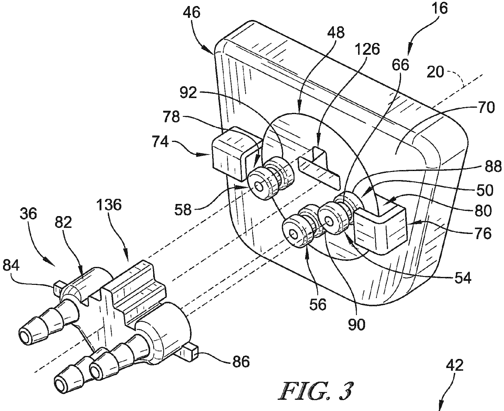
Fig. 3 is an exploded assembly view of the multi-port connector including an adaptor coupled to the respiratory circuit and a connector base coupled to the respiratory control unit; -
Fig. 4 is another exploded assembly view of the multi-port connector in a different orientation; -
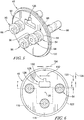
Fig. 5 is an enlarged perspective view of a receiver disk included in the connector base ofFigs. 3 and 4 ; -
Fig. 6 is an elevation view of the receiver disk showing that the receiver disks is formed to include a guide slot; -
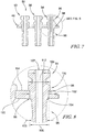
Fig. 7 is a sectional view taken along line 7-7 inFig. 6 showing that the receiver disk includes a disk body and a plurality of barbed conduits; -
Fig. 8 is an enlarged sectional view of the circled region inFig. 7 showing one of the plurality of barbed conduits coupled to the disk body with a friction-interference fit; -
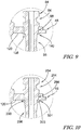
Fig. 9 is an enlarged sectional view similar toFig. 8 showing one of the plurality of barbed conduits coupled to the disk body with a friction-interference fit and with a pair of spot welds; and -
Fig. 10 is an enlarged sectional view similar toFigs. 7 and 8 showing another embodiment of a barbed conduit coupled to the disk body using a clip. - Referring to
Fig. 1 , arespiratory therapy device 10 is shown and is used by a respiratory therapist to deliver one or more respiratory therapies to a patient. Therespiratory therapy device 10 includesrespiratory control unit 12, arespiratory circuit 14, and amulti-port connector 16. Therespiratory control unit 12 is configured to provide the respiratory therapy. The respiratory therapy may include delivering a medicated aerosol or applying a composite therapy involving alternation between continuous high frequency oscillation (CHFO) therapy and continuous positive expiratory pressure (CPEP) therapy each in conjunction with the aerosol delivery. Therespiratory circuit 14 is configured to deliver the respiratory therapy to the patient from therespiratory control unit 12. An example of a suitablerespiratory control unit 12 and associatedrespiratory circuit 14 is shown and described inU.S. Patent No. 9,675,775, issued on June 13, 2017 respiratory control unit 12 andrespiratory circuit 14. - The
respiratory control unit 12 includes ahousing 18 that contains associated control unit equipment (not shown) for providing the respiratory therapy. Therespiratory control unit 12 further includes a plurality of visible components on an outer surface 24 of thehousing 18. The visible components include apressure manometer 26, anintensity switch 28 for selecting between a higher and lower percussive intensity, amode selector 30 for selecting between modes, anoxygen gas connector 32, and aflow adjustor 34 for regulating an amount of oxygen flow when in the CPEP mode. Theoxygen gas connector 32 is configured to be coupled to an external gas source such as a canister or a port on a wall in a healthcare facility. - The
respiratory circuit 14 includes anadaptor 36 that is configured to be coupled removably with themulti-port connector 16 as show inFig. 1 . Therespiratory circuit 14 further includes ahandset 38, anebulizer unit 40, and a plurality oftubular conduits 42 interconnecting theadaptor 36 to thehandset 38 andnebulizer unit 40. Thehandset 38 includes amouthpiece 44 that the patient uses to receive the respiratory therapy when therespiratory circuit 14 is coupled to therespiratory control unit 12 and therespiratory control unit 12 is on. Thenebulizer unit 40 is configured to convert a liquid medication into a mist so that the patient may breathe the medication into their lungs for the treatment of various conditions. However, in some embodiments, therespiratory circuit 14 may not include thenebulizer unit 40. The plurality ofconduits 42 are configured to transfer fluid, i.e. oxygen, from therespiratory control unit 12 to thehandset 38 and/or thenebulizer unit 40. In the illustrative embodiment, one of theconduits 42 is used for pressure sensing while the remaining twoconduits 42 conduct the fluid therethrough for treatment purposes. - The
multi-port connector 16 is also mounted to the outer surface 24 of thehousing 18 and is configured to receive theadaptor 36 of therespiratory circuit 14 to couple therespiratory circuit 14 to therespiratory control unit 12. The multi-port connector includes aconnector base 46, areceiver disk 48, and a plurality ofbarbed conduits 50 as shown inFigs. 2-4 . Theconnector base 46 is mounted to therespiratory control unit 12 in a generally central, accessible area. Thereceiver disk 48 coupled to theconnector base 46 for pivotable movement relative to theconnector base 46 about anaxis 20 between an unlocked orientation and a locked orientation. The plurality ofbarbed conduits 50 are coupled to thereceiver disk 48 for movement with thereceiver disk 48 relative to theconnector base 46 between the unlocked orientation and the locked orientation. - The
multi-port connector 16 and theadaptor 36 cooperate to provide a quick connect system for the coupling therespiratory circuit 14 to therespiratory control unit 12. The plurality ofbarbed conduits 50 illustratively include threebarbed conduits receiver disk 48 in a generally triangular arrangement. Theadaptor 36 is formed to include three correspondingopenings barbed conduits receiver disk 48 is in arranged in the unlocked orientation. With theopenings barbed conduits adaptor 36 may be pressed onto the multi-port connector such that a portion of eachbarbed conduit corresponding opening barbed conduits slot 66 to provide an annular sealing interface between an inner surface defining eachopening barbed conduits barbed conduits 50, theadaptor 36 andreceiver disk 48 may be rotated from the unlocked orientation to the locked orientation to block removal of theadaptor 36 from themulti-port connector 16. - The
connector base 46 cooperates with theadaptor 36 to block removal of theadaptor 36 from themulti-port connector 16 in the locked orientation. Theconnector base 46 includes abody plate 70 that is formed to include a central aperture 72, afirst retainer tab 74, and asecond retainer tab 76. Thebody plate 70 is mounted to thehousing 18 of therespiratory control unit 12 and is configured to retain thereceiver disk 48 in the central aperture 72. Thefirst retainer tab 74 is coupled to an external surface of thebody plate 70 on a first side of the central aperture 72. Thesecond retainer tab 76 is coupled to the external surface of thebody plate 70 on a second side of the central aperture 72 opposite the first side. Eachretainer tab slot body plate 70 and theretainer tab slots axis 20. Theslot 78 defined by thefirst retainer tab 74 opens downwardly while theslot 80 defined by thesecond retainer tab 76 opens upwardly. - The
adaptor 36 includes anadaptor body 82 and first andsecond lock tabs adaptor body 82. The first andsecond lock tabs slots second retainer tabs retainer tabs adaptor 36 from being coupled with the plurality ofbarbed conduits 50 when thereceiver disk 48 is arranged in the locked orientation. In the unlocked orientation, thelock tabs retainer tabs adaptor 36 may be coupled with the plurality ofbarbed conduits 50. Once coupled with the plurality ofbarbed conduits 50, theadaptor 36 and thereceiver disk 48 may be rotated in a clockwise direction to the locked orientation so that thelock tabs corresponding slot retainer tabs lock tabs axis 20 to block removal of theadaptor 36 from the plurality ofbarbed conduits 50. - In the illustrative embodiment, the
receiver disk 48 and each of thebarbed conduits receiver disk 48 and each of thebarbed conduits receiver disk 48 and each of thebarbed conduits receiver disk 48 and each of thebarbed conduits receiver disk 48 and each of thebarbed conduits robust receiver disk 48 andconduits 50 which would be subject to wear and tear if made from plastics materials and formed as one piece. - The
receiver disk 48 is illustratively formed as a metallic plate and is machined so that it is formed to include a plurality ofconduit apertures Figs. 3 and 4 . Eachaperture barbed conduit barbed conduits receiver disk 48 with a friction-interference fit. In the illustrative embodiment, the friction-interference fit between thereceiver disk 48 and each of thebarbed conduits barbed conduits adaptor 36 from thebarbed conduits - Each of the barbed conduits in the illustrative embodiment are identical. Accordingly, only one
barbed conduit 54 is described below and the features described forbarbed conduit 54 are hereby incorporated by reference forbarbed conduits barbed conduit 54 includes a generallycylindrical head section 94, abarbed section 96, and aretainer section 98 as shown inFigs. 5-8 . Thehead section 94 protrudes axially away from from thereceiver disk 48 relative to theaxis 20 so that it is accessible at an exterior of thehousing 18 for receiving theadaptor 36. Thebarbed section 96 extends axially away from thereceiver disk 48 into thehousing 18. Thebarbed section 96 is configured receive acorresponding conduit 100 for conducting fluid through themulti-port connector 16 from therespiratory control unit 12 to therespiratory circuit 14. Theretainer section 98 interconnects thehead section 94 and thebarbed section 96 and engages thereceiver disk 48 to provide the friction-interference fit between thebarbed conduit 54 and thereceiver disk 48. - The
retainer section 98 has anouter diameter 102 while the correspondingaperture 88 that receives thebarbed conduit 54 is defined by awall 104 with aninner diameter 106 as shown inFig. 8 . Theouter diameter 102 of theretainer section 98 is greater than theinner diameter 106 of thewall 104 defining theaperture 88. Theouter diameter 102 of the retainer section and theinner diameter 106 of thewall 104 defining theaperture 88 are sized selectively to provide the friction-interference fit that withstands the predetermined pull force. - In the illustrative embodiment, the
outer diameter 102 is greater than or equal to about 5.8 mm. In some embodiments, theouter diameter 102 is within a range of 5.819 mm to 5.827 mm. In the illustrative embodiment, theinner diameter 106 is equal to about 5.8 mm. In some embodiments, theouter diameter 102 is within a range of 5.8 mm to 5.812 mm. In some embodiments, theouter diameter 102 is about 0.34% larger than theinner diameter 106 to provide the friction-interference fit with the predetermine pull force. The percent difference between theouter diameter 102 and theinner diameter 106 may vary due to the tolerances described above. - An
outermost diameter 108 of thebarbed section 96 is less than theinner diameter 106 so that thebarbed conduit 54 may be inserted through theaperture 88 with thebarbed section 96 extending therethrough first. Thehead section 94 includes ashoulder 110 positioned directly adjacent to theretainer section 98. Theshoulder 110 has anouter diameter 112 that is greater than theouter diameter 102 of theretainer section 98. Theretainer section 98 of thebarbed conduit 54 is press fit through theaperture 88 to provide the friction-interference fit until anouter surface 114 of thereceiver disk 48 engages theshoulder 110 of thehead section 94. In some embodiments, theshoulder 110 may be omitted and theretainer section 98 may gradually increase in diameter such that, when press fit through theaperture 88, the increase in diameter stops further insertion of thebarbed conduit 54 at a predetermined point. - A
fluid passageway 107 extends through thebarbed conduit 54 and has a substantiallyconstant diameter 109 as shown inFig. 8 . Thediameter 109 in the illustrative embodiment is equal to about 2.25 mm with a bi-directional tolerance of about 0.05 mm. Thediameter 109 is sized to conduct fluid therethrough in a manner that provides the adequate respiratory therapy performance from therespiratory control unit 12. In other embodiments, thediameter 109 may vary to provide desired fluid properties for other settings in which themulti-port connector 16 is used. - The
receiver disk 48 is also formed to include afirst detent notch 116 and asecond detent notch 118 spaced apart circumferentially from thefirst detent notch 116 about theaxis 20 as shown inFig. 6 . Thefirst detent notch 116 and thesecond detent notch 118 are formed in aback side 120 of the receiver disk and extend inwardly from anouter edge 122 of thereceiver disk 48 toward theaxis 20. In the illustrative embodiment, the first andsecond detent notches connector base 46 includes a fixeddetent tab 124 that engages thefirst detent notch 116 when thereceiver disk 48 is in the unlocked orientation and engaged thesecond detent notch 118 when thereceiver disk 48 is in the locked orientation as shown inFig. 4 . - In the illustrative embodiment, the
receiver disk 48 is also formed to include aguide slot 126 as shown inFigs. 3-6 . Theguide slot 126 is defined by a firstrectangular portion 128 andsecond arm portion 130. Therectangular portion 128 extends transversely along thereceiver disk 48 and has alength 132 and aheight 133. Thearm portion 130 opens into therectangular portion 128 and extends away from therectangular portion 128 generally perpendicular to therectangular portion 128. Thearm portion 130 is located about midway along thelength 132 of therectangular portion 128 and has alength 134 and aheight 135. Thelength 132 of therectangular portion 128 is greater than thelength 134 of thearm portion 130. Theheight 133 of therectangular portion 128 is greater than theheight 135 of thearm portion 130. - The
adaptor 36 further includes aguide post 136 with a shape that matches theguide slot 126 as shown inFig. 4 . Theguide post 136 facilitates coupling of theadaptor 36 with the plurality ofbarbed conduits 50 in the proper orientation. Theguide post 136 also supports loads acting on theadaptor 36 as theadaptor 36 and thereceiver disk 48 are moved between the unlocked orientation and the locked orientation. - In some embodiments, the friction-interference fit between each of the
barbed conduits receiver disk 48 may be reinforced as shown inFigs. 9 and 10 . For example, thebarbed conduit 54 may include at least onespot weld receiver disk 48 and thebarbed conduit 54. In the illustrative embodiment shown inFig. 9 , afirst spot weld 138 and asecond spot weld 140 are located at interface points between thereceiver disk 48 and the retainer section along theback side 120 of thereceiver disk 48. Thefirst spot weld 138 and thesecond spot weld 140 are located on opposite sides of thebarbed conduit 54 from one another. It should be appreciated that any suitable number of spot welds may be used. Other types of metal joining processes may also be used such as brazing and soldering, for example. - In the illustrative embodiment, the
multi-port connector 16 is used with arespiratory therapy device 10. However, it should be appreciated that the illustrativemulti-port connector 16 described herein may be used in other settings that require a multi-port connection. - Another embodiment of a
barbed conduit 254 is shown inFig. 10 . Thebarbed conduit 254 is similar tobarbed conduit 54 shown inFigs. 3-9 and described above. Thebarbed conduit 254 includes ahead section 294, abarbed section 296, aretainer section 298, and aslot section 299. Theslot section 299 is positioned directly adjacent to theretainer section 298 and theback side 120 of thereceiver disk 48. Theslot section 299 is sized to receive aclip 301 that engages theback side 120 of thereceiver disk 48 and anedge 303 of theslot section 299. Theclip 301 is illustratively embodied as a circlip and helps retain thebarbed conduit 254 to thereceiver disk 48 in conjunction with the friction-interference fit between theretainer section 298 and thereceiver disk 48. - Although certain illustrative embodiments have been described in detail above, variations and modifications exist.
- Embodiments of the invention can be described with reference to the following numbered clauses, with preferred features laid out in the dependent clauses:
- 1. A multi-port connector for a respiratory therapy device comprising
a connector base,
a receiver disk coupled to the connector base, and
a plurality of barbed conduits, the receiver disk being formed to include a plurality of apertures with a first diameter, each of the plurality of barbed conduits including a retainer section with a second diameter that is greater than the first diameter so that each barbed conduit forms a friction-interference fit between the receiver disk and each retainer section. - 2. The multi-port connector of clause 1, wherein the receiver disk is coupled to the connector base for pivotable movement relative to the connector base about an axis between an unlocked orientation and a locked orientation and an adaptor is configured to be coupled to the plurality of barbed conduits when the receiver disk is in the unlocked orientation.
- 3. The multi-port connector of clause 2, wherein the connector base includes a body plate with a central opening sized to receive the receiver disk and first and second retainer tabs coupled to the body plate on opposite sides of the central opening, the first and second retainer tabs providing first and second slots between the body plate and first and second retainer tabs.
- 4. The multi-port connector of clause 3, wherein the adaptor includes an adaptor body and first and second lock tabs coupled to opposite sides of the adaptor body and that extend radially outward from the adaptor body in opposite directions, the first and second lock tabs being sized to extend into the first and second slots when the adaptor is coupled to the plurality of barbed conduits and the receiver disk is subsequently rotated to the locked orientation.
- 5. The multi-port connector of any preceding clause, wherein the receiver disk and the plurality of barbed conduits comprise metallic materials.
- 6. The multi-port connector of clause 5, wherein the receiver disk and the plurality of barbed conduits comprise stainless steel.
- 7. The multi-port connector of any preceding clause, wherein the second diameter is sized selectively so that the friction-interference fit is able to withstand a predetermined pull force.
- 8. The multi-port connector of
clause 7, wherein the predetermined pull force is at least 200 Newtons. - 9. The multi-port connector of clause 8, wherein the second diameter is about 0.34% larger than the first diameter to provide the friction-interference fit.
- 10. The multi-port connector of any preceding clause, wherein the receiver disk is formed to include a first detent notch and a second detent notch spaced apart circumferentially from the first detent notch by about 45 degrees about the axis.
- 11. The multi-port connector of
clause 10, wherein the first detent notch and the second detent notch are formed in a back side of the receiver disk and extend inwardly from an outer edge of the receiver disk toward the axis. - 12. The multi-port connector of either
clause 10 or clause 11, wherein the connector base includes a detent tab that engages the first detent notch when the receiver disk is in the unlocked orientation and engages the second detent notch when the receiver disk is in the locked orientation. - 13. The multi-port connector of any preceding clause, wherein each of the plurality of barbed conduits includes a first spot weld and a second spot weld each located at interface points between the receiver disk and the retainer section along a back side of the receiver disk.
- 14. The multi-port connector of clause 13, wherein the first spot weld and the second spot weld are located on opposite sides of each barbed conduit.
- 15. The multi-port connector of any preceding clause, wherein each of the plurality of barbed conduits further includes a slot section directly adjacent to the retainer section, and each slot section is sized to receive a clip that engages a back side of the receiver disk and an edge of the slot section.
- 16. The multi-port connector of any preceding clause, wherein the receiver disk is formed to include a guide slot with a first rectangular portion that extends along a first axis and second portion opening into the first portion that extends along a second axis that is perpendicular to the first axis.
- 17. The multi-port connector of
clause 16, wherein the adaptor includes a guide post with a shape that matches the guide slot. - 18. A respiratory therapy device comprising
a respiratory control unit configured to provide at least one respiratory therapy for a user,
a respiratory circuit coupled to the respiratory control unit to deliver the respiratory therapy to the user, the respiratory circuit including an adaptor configured to be coupled to the connector base, and
a multi-port connector interconnecting the respiratory circuit to the respiratory control unit, the multi-port connector comprising,
a connector base coupled to the respiratory control unit,
a receiver disk coupled to the connector base, and
a plurality of barbed conduits coupled to the receiver disk, the receiver disk being formed to include a plurality of apertures with a first diameter, and each of the plurality of barbed conduits including a retainer section with a second diameter greater than the first diameter so that each barbed conduit forms a friction-interference fit between the receiver disk and the retainer section. - 19. The respiratory therapy device of
clause 18, wherein the receiver disk is coupled to the connector base for pivotable movement relative to the connector base about an axis between an unlocked orientation and a locked orientation and the adaptor is configured to be coupled to the plurality of barbed conduits when the receiver disk is in the unlocked orientation. - 20. The respiratory therapy device of clause 19, wherein the connector base includes a body plate with a central opening sized to receive the receiver disk and first and second retainer tabs coupled to the body plate on opposite sides of the central opening, the first and second retainer tabs providing first and second slots between the body plate and first and second retainer tabs.
- 21. The respiratory therapy device of
clause 20, wherein the adaptor includes an adaptor body and first and second lock tabs coupled to opposite sides of the adaptor body and that extend radially outward from the adaptor body in opposite directions, the first and second lock tabs being sized to extend into the first and second slots when the adaptor is coupled to the plurality of barbed conduits and the receiver disk is subsequently rotated to the locked orientation. - 22. The respiratory therapy device of any one of
clauses 18 to 21, wherein the receiver disk and the plurality of barbed conduits comprise metallic materials. - 23. The respiratory therapy device of clause 22, wherein the receiver disk and the plurality of barbed conduits comprise stainless steel.
- 24. The respiratory therapy device of any one of
clauses 18 to 23, wherein the second diameter is sized selectively so that the friction-interference fit is able to withstand a predetermined pull force. - 25. The respiratory therapy device of clause 24, wherein the predetermined pull force is at least 200 Newtons.
- 26. The respiratory therapy device of clause 25, wherein the second diameter is about 0.34% larger than the first diameter to provide the friction-interference fit.
- 27. The respiratory therapy device of any one of
clauses 18 to 26, wherein the receiver disk is formed to include a first detent notch and a second detent notch spaced apart circumferentially from the first detent notch by about 45 degrees about the axis. - 28. The respiratory therapy device of clause 27, wherein the first detent notch and the second detent notch are formed in a back side of the receiver disk and extend inwardly from an outer edge of the receiver disk toward the axis.
- 29. The respiratory therapy device of either clause 27 or
clause 28, wherein the connector base includes a detent tab that engages the first detent notch when the receiver disk is in the unlocked orientation and engages the second detent notch when the receiver disk is in the locked orientation. - 30. The respiratory therapy device of any one of
clauses 18 to 29, wherein each of the plurality of barbed conduits includes a first spot weld and a second spot weld each located at interface points between the receiver disk and the retainer section along a back side of the receiver disk. - 31. The respiratory therapy device of
clause 30, wherein the first spot weld and the second spot weld are located on opposite sides of each barbed conduit. - 32. The respiratory therapy device of any one of
clauses 18 to 31, wherein each of the plurality of barbed conduits further includes a slot section directly adjacent to the retainer section, and each slot section is sized to receive a clip that engages a back side of the receiver disk and an edge of the slot section. - 33. The respiratory therapy device of any one of
clauses 18 to 32, wherein the receiver disk is formed to include a guide slot with a first rectangular portion that extends along a first axis and second portion opening into the first portion that extends along a second axis that is perpendicular to the first axis. - 34. The respiratory therapy device of clause 33, wherein the adaptor includes a guide post with a shape that matches the guide slot.
- 35. The respiratory therapy device of any one of
clauses 18 to 34, wherein each of the plurality of barbed conduits has a fluid passageway extending therethrough with a substantially constant diameter that is equal to about 2.25 mm. - 36. A method of forming a quick disconnect multi-port connector for a respiratory therapy device, the method comprising
providing a disk made from metallic materials,
machining a plurality of apertures through the disk,
providing a plurality of tubes made from metallic materials,
machining each of the tubes to include an outer surface with a plurality of barb sections and an inner surface defining a fluid passageway that extends through each of the tubes, one of the barb sections forming a retainer section with an outer diameter that is greater than each of the apertures formed in the disk,
inserting one of the plurality of tubes into each aperture formed in the disk, the retainer section of each of the plurality of tubes interfacing with a wall defining each aperture to form a friction-interference fit between the disk and the retainer section to couple each tube to the disk. - 37. The method of
clause 36, further comprising the step of spot welding each of the tubes to the disk at an interface point between the retainer section and the disk. - 38. The method of clause 37, wherein each tube has a first spot weld on a first side of the tube at the interface point between the retainer section and the disk and a second spot weld on a second side of the tube opposite the first side at the interface point between the retainer section and the disk.
- 39. The method of any one of
clauses 36 to 38, wherein the step of machining each of the tubes further includes machining a slot section into each tube adjacent to each retainer section and the step of inserting further includes inserting a clip into the slot section between the disk and an edge of the slot section. - 40. The method of any one of
clauses 36 to 39, wherein the step of machining the apertures in the disk further includes polishing the walls defining each of the apertures to remove sharp edges. - 41. The method of any one of
clauses 36 to 40, wherein the metallic materials of the disk and the plurality of tubes comprise stainless steel.
Claims (15)
- A respiratory therapy device comprising
a respiratory control unit configured to provide at least one respiratory therapy for a user,
a respiratory circuit coupled to the respiratory control unit to deliver the respiratory therapy to the user, the respiratory circuit including an adaptor configured to be coupled to the connector base, and
a multi-port connector interconnecting the respiratory circuit to the respiratory control unit, the multi-port connector comprising,a connector base coupled to the respiratory control unit,a receiver disk coupled to the connector base, anda plurality of barbed conduits coupled to the receiver disk, the receiver disk being formed to include a plurality of apertures with a first diameter, and each of the plurality of barbed conduits including a retainer section with a second diameter greater than the first diameter so that each barbed conduit forms a friction-interference fit between the receiver disk and the retainer section. - The respiratory therapy device of claim 1, wherein the receiver disk is coupled to the connector base for pivotable movement relative to the connector base about an axis between an unlocked orientation and a locked orientation and the adaptor is configured to be coupled to the plurality of barbed conduits when the receiver disk is in the unlocked orientation.
- The respiratory therapy device of claim 2, wherein the connector base includes a body plate with a central opening sized to receive the receiver disk and first and second retainer tabs coupled to the body plate on opposite sides of the central opening, the first and second retainer tabs providing first and second slots between the body plate and first and second retainer tabs.
- The respiratory therapy device of claim 3, wherein the adaptor includes an adaptor body and first and second lock tabs coupled to opposite sides of the adaptor body and that extend radially outward from the adaptor body in opposite directions, the first and second lock tabs being sized to extend into the first and second slots when the adaptor is coupled to the plurality of barbed conduits and the receiver disk is subsequently rotated to the locked orientation.
- The respiratory therapy device of any preceding claim, wherein the receiver disk and the plurality of barbed conduits comprise metallic materials,
and wherein preferably the receiver disk and the plurality of barbed conduits comprise stainless steel. - The respiratory therapy device of any preceding claim, wherein the second diameter is sized selectively so that the friction-interference fit is able to withstand a predetermined pull force,
and wherein preferably the predetermined pull force is at least 200 Newtons. - The respiratory therapy device of claim 6, wherein the second diameter is about 0.34% larger than the first diameter to provide the friction-interference fit.
- The respiratory therapy device of any preceding claim, wherein the receiver disk is formed to include a first detent notch and a second detent notch spaced apart circumferentially from the first detent notch by about 45 degrees about the axis.
- The respiratory therapy device of claim 8, wherein the first detent notch and the second detent notch are formed in a back side of the receiver disk and extend inwardly from an outer edge of the receiver disk toward the axis.
- The respiratory therapy device of either claim 8 or claim 9, wherein the connector base includes a detent tab that engages the first detent notch when the receiver disk is in the unlocked orientation and engages the second detent notch when the receiver disk is in the locked orientation.
- The respiratory therapy device of any preceding claim, wherein each of the plurality of barbed conduits includes a first spot weld and a second spot weld each located at interface points between the receiver disk and the retainer section along a back side of the receiver disk,
and wherein preferably the first spot weld and the second spot weld are located on opposite sides of each barbed conduit. - The respiratory therapy device of any preceding claim, wherein each of the plurality of barbed conduits further includes a slot section directly adjacent to the retainer section, and each slot section is sized to receive a clip that engages a back side of the receiver disk and an edge of the slot section.
- The respiratory therapy device of any preceding claim, wherein the receiver disk is formed to include a guide slot with a first rectangular portion that extends along a first axis and second portion opening into the first portion that extends along a second axis that is perpendicular to the first axis.
- The respiratory therapy device of claim 13, wherein the adaptor includes a guide post with a shape that matches the guide slot.
- The respiratory therapy device of any preceding claim, wherein each of the plurality of barbed conduits has a fluid passageway extending therethrough with a substantially constant diameter that is equal to about 2.25 mm.
Applications Claiming Priority (1)
| Application Number | Priority Date | Filing Date | Title |
|---|---|---|---|
| US201962933569P | 2019-11-11 | 2019-11-11 |
Publications (2)
| Publication Number | Publication Date |
|---|---|
| EP3819001A1 true EP3819001A1 (en) | 2021-05-12 |
| EP3819001B1 EP3819001B1 (en) | 2025-09-10 |
Family
ID=73138735
Family Applications (1)
| Application Number | Title | Priority Date | Filing Date |
|---|---|---|---|
| EP20205983.8A Active EP3819001B1 (en) | 2019-11-11 | 2020-11-05 | Respiratory therapy device with multi-port connector |
Country Status (4)
| Country | Link |
|---|---|
| US (1) | US12070554B2 (en) |
| EP (1) | EP3819001B1 (en) |
| JP (1) | JP2021087770A (en) |
| CN (1) | CN213941772U (en) |
Citations (3)
| Publication number | Priority date | Publication date | Assignee | Title |
|---|---|---|---|---|
| EP2317200A1 (en) * | 2009-11-02 | 2011-05-04 | Comedica Incorporated | Multiple conduit connector apparatus |
| US20140144446A1 (en) * | 2012-11-26 | 2014-05-29 | John Alan Bobey | Respiratory therapy device and filtration units therefor |
| WO2015197605A1 (en) * | 2014-06-25 | 2015-12-30 | Intersurgical Ag | Respiratory connector |
Family Cites Families (176)
| Publication number | Priority date | Publication date | Assignee | Title |
|---|---|---|---|---|
| US402779A (en) | 1889-05-07 | Emphysema | ||
| US1150238A (en) | 1915-02-06 | 1915-08-17 | Dave Winbray | Aerating device. |
| US2475468A (en) | 1945-11-02 | 1949-07-05 | M O Valve Co Ltd | Detachable union for cooling systems |
| US2510125A (en) | 1946-07-30 | 1950-06-06 | Lawrence W Meakin | Connector for fluid or electrical lines or both |
| US2837749A (en) | 1954-07-22 | 1958-06-10 | Gross Lothar | Multiple water pipe connecting device |
| US2788991A (en) | 1955-04-04 | 1957-04-16 | Reda Turner Mfg Company Inc | Disconnecting adapter for adjacent joints of parallel pipes |
| US3083707A (en) | 1956-02-13 | 1963-04-02 | Henry W Seeler | Device for treatment of pulmonary diseases |
| SE221323C1 (en) | 1962-10-25 | 1968-07-02 | Carl-Gunnar Daniel Engstroem | Device for imparting a content of aerosol in a respirator gas |
| US3301255A (en) | 1963-10-18 | 1967-01-31 | Harris A Thompson | Method and apparatus for application of nebulized medication in positive pressure respiratory equipment |
| DE1575050A1 (en) | 1966-01-12 | 1972-04-13 | Misto Gen Equipment Co | Ultrasonic fog generator |
| GB1138274A (en) | 1966-03-04 | 1968-12-27 | Liston Fletcher Inc | Therapeutic respirator |
| US3469863A (en) | 1967-04-05 | 1969-09-30 | Trico Products Corp | Fluid coupling assembly |
| US3561444A (en) | 1968-05-22 | 1971-02-09 | Bio Logics Inc | Ultrasonic drug nebulizer |
| US3584621A (en) | 1968-10-31 | 1971-06-15 | Bird F M | Respiratory apparatus |
| US4182599A (en) | 1973-10-02 | 1980-01-08 | Chemetron Corporation | Volume-rate respirator system and method |
| US4054134A (en) | 1975-09-15 | 1977-10-18 | Kritzer Richard W | Respirators |
| US4062358A (en) | 1976-04-21 | 1977-12-13 | Kritzer Richard W | Respirators |
| US4436090A (en) | 1979-01-22 | 1984-03-13 | Darling Phillip H | Piston actuated, pilot valve operated breathing regulator |
| US4245633A (en) | 1979-01-31 | 1981-01-20 | Erceg Graham W | PEEP providing circuit for anesthesia systems |
| DE3023648A1 (en) | 1980-06-24 | 1982-01-21 | Jaeger, Erich, 8700 Würzburg | DEVICE FOR EXAMINING THE RESPIRATORY RESPIRATORY SENSITIVITY |
| US4770164A (en) | 1980-10-16 | 1988-09-13 | Lach Ralph D | Resuscitation method and apparatus |
| US4635857A (en) | 1980-12-08 | 1987-01-13 | Vortran Corporation | Atomizing apparatus |
| SE430213B (en) | 1981-03-10 | 1983-10-31 | Siemens Elema Ab | RESPIRATOR INTENDED TO BE CONNECTED TO THE HUMAN OR ANIMAL PATIENTS |
| US4601465A (en) | 1984-03-22 | 1986-07-22 | Roy Jean Yves | Device for stimulating the human respiratory system |
| US4630847A (en) | 1984-10-05 | 1986-12-23 | Colder Products Company | Multiple tube connector |
| US4703957A (en) | 1984-10-05 | 1987-11-03 | Colder Products Company | Miniature tube fitting having a barbed stem portion surrounded by a protective shroud and method for making same |
| US5150291A (en) | 1986-03-31 | 1992-09-22 | Puritan-Bennett Corporation | Respiratory ventilation apparatus |
| GB8704104D0 (en) | 1987-02-21 | 1987-03-25 | Manitoba University Of | Respiratory system load apparatus |
| US4981295A (en) | 1987-05-11 | 1991-01-01 | City Of Hope | Respiratory training using feedback |
| US5322057A (en) | 1987-07-08 | 1994-06-21 | Vortran Medical Technology, Inc. | Intermittent signal actuated nebulizer synchronized to operate in the exhalation phase, and its method of use |
| ATE67686T1 (en) | 1987-10-22 | 1991-10-15 | Varioraw Percutive Sa | ANTI-EXHALATION RESISTANCE DEVICE TO IMPROVE LUNG VENTILATION. |
| DK168888A (en) | 1988-03-25 | 1989-09-26 | Ambu Int As | RESPIRATION TRAINING DEVICE |
| US4951659A (en) | 1988-11-04 | 1990-08-28 | Automatic Liquid Packaging, Inc. | Nebulizer with cooperating disengageable on-line heater |
| EP0372148A1 (en) | 1988-12-09 | 1990-06-13 | Erik Folke Norell | Lung exercising device |
| US4964404A (en) | 1989-04-19 | 1990-10-23 | Stone William C | Breathing apparatus |
| BE1004384A3 (en) | 1989-08-03 | 1992-11-10 | Labaere Emmanuel | Device for applying on and techniques exhalation. |
| US5632269A (en) | 1989-09-22 | 1997-05-27 | Respironics Inc. | Breathing gas delivery method and apparatus |
| US5069449A (en) | 1990-01-26 | 1991-12-03 | Wardwell Mary M | Strap device for increasing lung capacity |
| US5127400A (en) | 1990-03-23 | 1992-07-07 | Bird Products Corp. | Ventilator exhalation valve |
| DE69103061T2 (en) | 1990-03-27 | 1994-11-17 | Boc Group Plc | Anesthetic evaporator. |
| US5027809A (en) | 1990-05-17 | 1991-07-02 | Robinson Pat D | "Peeper" performance hand held nebuilizer attachment with adjustability of expiratory pressures and expiratory restriction |
| AU641268B2 (en) | 1990-07-27 | 1993-09-16 | Franco Del Bon | Inhalation device |
| US5938117A (en) | 1991-04-24 | 1999-08-17 | Aerogen, Inc. | Methods and apparatus for dispensing liquids as an atomized spray |
| US6540154B1 (en) | 1991-04-24 | 2003-04-01 | Aerogen, Inc. | Systems and methods for controlling fluid feed to an aerosol generator |
| US5277175A (en) | 1991-07-12 | 1994-01-11 | Riggs John H | Continuous flow nebulizer apparatus and method, having means maintaining a constant-level reservoir |
| US5261394A (en) | 1991-09-30 | 1993-11-16 | Triangle Research And Development Corporation | Percussive aid for the treatment of chronic lung disease |
| CH685475A5 (en) | 1992-04-10 | 1995-07-31 | Varioraw Percutive Sa | specific therapeutic device in the respiratory field. |
| GB2273660B (en) | 1992-09-11 | 1996-07-17 | Aid Medic Ltd | Drug delivery arrangement |
| FR2695830B1 (en) | 1992-09-18 | 1994-12-30 | Pierre Medical Sa | Breathing aid device. |
| DE4232298A1 (en) | 1992-09-26 | 1994-03-31 | Lang Volker | Flow and volumetric measuring device for artificial respirator - has flow sensor which is automatically switched to carry out automatic calibration by alternately switching from patient to calibration lung |
| US5439430A (en) | 1993-05-10 | 1995-08-08 | Rubens; Louis C. | Respiratory exerciser |
| GB2279014B (en) | 1993-06-02 | 1997-07-16 | Niall Keaney | Device for controlling delivery of respiratory drugs |
| US5398676A (en) | 1993-09-30 | 1995-03-21 | Press; Roman J. | Portable emergency respirator |
| US6425393B1 (en) | 1993-11-09 | 2002-07-30 | Cprx Llc | Automatic variable positive expiratory pressure valve and methods |
| US6604523B2 (en) | 1993-11-09 | 2003-08-12 | Cprx Llc | Apparatus and methods for enhancing cardiopulmonary blood flow and ventilation |
| US5570682A (en) | 1993-12-14 | 1996-11-05 | Ethex International, Inc. | Passive inspiratory nebulizer system |
| ATE178498T1 (en) | 1994-01-12 | 1999-04-15 | Saime Sarl | VENTILATORY USING A LOW PRESSURE RESPIRATORY SUPPORT METHOD |
| US5562618A (en) | 1994-01-21 | 1996-10-08 | Sims Deltec, Inc. | Portal assembly and catheter connector |
| US5598839A (en) | 1994-04-20 | 1997-02-04 | Diemolding Corporation | Positive expiratory pressure device |
| US5535738A (en) | 1994-06-03 | 1996-07-16 | Respironics, Inc. | Method and apparatus for providing proportional positive airway pressure to treat sleep disordered breathing |
| US6932084B2 (en) | 1994-06-03 | 2005-08-23 | Ric Investments, Inc. | Method and apparatus for providing positive airway pressure to a patient |
| US6105575A (en) | 1994-06-03 | 2000-08-22 | Respironics, Inc. | Method and apparatus for providing positive airway pressure to a patient |
| US5642730A (en) | 1994-06-17 | 1997-07-01 | Trudell Medical Limited | Catheter system for delivery of aerosolized medicine for use with pressurized propellant canister |
| ZA954936B (en) | 1994-06-17 | 1996-02-27 | Trudell Medical Ltd | Nebulizing catheter system and methods of use and manufacture |
| US6729334B1 (en) | 1994-06-17 | 2004-05-04 | Trudell Medical Limited | Nebulizing catheter system and methods of use and manufacture |
| EP0814861B1 (en) | 1995-03-14 | 2002-06-05 | Siemens Aktiengesellschaft | Ultrasonic atomizer device with removable precision dosing unit |
| IL117473A (en) | 1995-03-14 | 2001-08-26 | Siemens Ag | Ultrasonic atomizer device with removable precision dosating unit |
| US6085740A (en) | 1996-02-21 | 2000-07-11 | Aerogen, Inc. | Liquid dispensing apparatus and methods |
| US5666945A (en) | 1995-06-07 | 1997-09-16 | Salter Labs | Pneumatically-operated gas demand apparatus |
| US5617847A (en) | 1995-10-12 | 1997-04-08 | Howe; Stephen L. | Assisted breathing apparatus and tubing therefore |
| FR2740691B1 (en) | 1995-11-02 | 1998-01-09 | France Etat | MODULATOR BACK PRESSURE CARTRIDGE FOR RESPIRATORY MASK |
| US6463930B2 (en) | 1995-12-08 | 2002-10-15 | James W. Biondi | System for automatically weaning a patient from a ventilator, and method thereof |
| US5823179A (en) | 1996-02-13 | 1998-10-20 | 1263152 Ontario Inc. | Nebulizer apparatus and method |
| US5906198A (en) | 1996-07-16 | 1999-05-25 | Flickinger; William J. | Nasal nebulizer |
| US6152134A (en) | 1996-10-18 | 2000-11-28 | Invacare Corporation | Oxygen conserving device |
| US6058932A (en) | 1997-04-21 | 2000-05-09 | Hughes; Arthur R. | Acoustic transceiver respiratory therapy apparatus |
| US5829429A (en) | 1997-04-21 | 1998-11-03 | Hughes; Arthur R. | Acoustic respiratory therapy apparatus |
| US6571790B1 (en) | 1997-05-12 | 2003-06-03 | Robert E. Weinstein | Method and device for organizing and coordinating the combined use of liquid medications for continuous nebulization for the treatment of respiratory disorders |
| US6076520A (en) | 1997-05-12 | 2000-06-20 | Cooper; Emily L. | Device for nasal therapeutic inhalation |
| US6044841A (en) | 1997-08-29 | 2000-04-04 | 1263152 Ontario Inc. | Breath actuated nebulizer with valve assembly having a relief piston |
| US6598603B1 (en) | 1997-12-31 | 2003-07-29 | Astra Aktiebolag | Method for treating respiratory diseases |
| US5992894A (en) * | 1998-03-05 | 1999-11-30 | Eaton Corporation | Plural conduit quick-connect |
| US6085746A (en) | 1998-03-17 | 2000-07-11 | Sensormedics Corporation | Oscillating ventilator apparatus and method |
| US6170882B1 (en) | 1998-04-13 | 2001-01-09 | J. David Prest | Coupling for waste water outlets |
| US6550476B1 (en) | 1998-05-21 | 2003-04-22 | Steven L. Ryder | Heat-moisture exchanger and nebulization device |
| US6908416B2 (en) * | 1998-07-23 | 2005-06-21 | Unisen, Inc. | Exercise and therapeutic trainer |
| SE9802827D0 (en) | 1998-08-25 | 1998-08-25 | Siemens Elema Ab | ventilator |
| US6234167B1 (en) | 1998-10-14 | 2001-05-22 | Chrysalis Technologies, Incorporated | Aerosol generator and methods of making and using an aerosol generator |
| US6575164B1 (en) | 1998-10-15 | 2003-06-10 | Ntc Technology, Inc. | Reliability-enhanced apparatus operation for re-breathing and methods of effecting same |
| AU1210500A (en) | 1998-10-21 | 2000-05-08 | Airsep Corporation | Combined oxygen regulator and conservation device |
| EP1126890A4 (en) | 1998-11-06 | 2003-08-13 | Salter Labs | MOUTHPIECE AND ACCESSORIES FOR NEBULIZER |
| DE1005917T1 (en) | 1998-12-01 | 2001-01-11 | Microflow Engineering S.A., Neuenburg/Neuchatel | Inhaler with ultrasonic atomizer, the spray openings of which are superimposed on the maximum amplitudes of a standing wave pattern |
| US6102042A (en) | 1998-12-22 | 2000-08-15 | Respironics, Inc. | Insufflation system, attachment and method |
| EP2263730A3 (en) | 1999-01-15 | 2017-03-15 | Resmed Limited | Method and apparatus to counterbalance intrinsic positive end expiratory pressure |
| US6240919B1 (en) | 1999-06-07 | 2001-06-05 | Macdonald John J. | Method for providing respiratory airway support pressure |
| US6920875B1 (en) | 1999-06-15 | 2005-07-26 | Respironics, Inc. | Average volume ventilation |
| US6615831B1 (en) | 1999-07-02 | 2003-09-09 | Respironics, Inc. | Pressure support system and method and a pressure control valve for use in such system and method |
| SE9902627D0 (en) | 1999-07-08 | 1999-07-08 | Siemens Elema Ab | Medical nebulizer |
| US6805120B1 (en) | 1999-09-20 | 2004-10-19 | Fisher & Paykel Healthcare Limited | Breathing assistance apparatus |
| US6694969B1 (en) | 1999-09-22 | 2004-02-24 | Instrumentarium Corp. | Method to improve oxygenation in subjects suffering impaired oxygenation |
| US6581596B1 (en) | 1999-09-24 | 2003-06-24 | Respironics, Inc. | Apparatus and method of providing high frequency variable pressure to a patient |
| US6415791B1 (en) | 1999-10-04 | 2002-07-09 | American Biosystems, Inc. | Airway treatment apparatus with cough inducement |
| WO2001026721A1 (en) | 1999-10-14 | 2001-04-19 | The Trustees Of Boston University | Variable peak pressure ventilation method and system |
| WO2001028887A1 (en) * | 1999-10-16 | 2001-04-26 | Glaxo Group Limited | Device housing for an aerosol container |
| US7059324B2 (en) | 1999-11-24 | 2006-06-13 | Smiths Medical Asd, Inc. | Positive expiratory pressure device with bypass |
| US6776159B2 (en) | 1999-11-24 | 2004-08-17 | Dhd Healthcare Corporation | Positive expiratory pressure device with bypass |
| US6581598B1 (en) | 1999-11-24 | 2003-06-24 | Dhd Healthcare Corporation | Positive expiratory pressure device |
| US6412481B1 (en) | 1999-12-23 | 2002-07-02 | Robert Bienvenu | Sealed backpressure attachment device for nebulizer |
| DE19962280A1 (en) | 1999-12-23 | 2001-07-12 | Draeger Medizintech Gmbh | Ultrasonic evaporator for liquids has exciter circuit to operate transducer at optimum vibration range |
| US6755446B2 (en) | 2000-02-11 | 2004-06-29 | Superior Workshop Tool Company | Waste pipe connector |
| CA2635489A1 (en) | 2000-02-11 | 2001-08-16 | Respironics Respiratory Drug Delivery (Uk) Ltd | Drug delivery apparatus |
| CA2826724C (en) | 2000-04-11 | 2016-02-02 | Trudell Medical International | Aerosol delivery apparatus with positive expiratory pressure capacity |
| US7971588B2 (en) | 2000-05-05 | 2011-07-05 | Novartis Ag | Methods and systems for operating an aerosol generator |
| US7600511B2 (en) | 2001-11-01 | 2009-10-13 | Novartis Pharma Ag | Apparatus and methods for delivery of medicament to a respiratory system |
| US6355002B1 (en) | 2000-05-22 | 2002-03-12 | Comedica Technologies Incorporated | Lung inflection point monitor apparatus and method |
| US7204245B2 (en) | 2000-07-06 | 2007-04-17 | Clinical Technologies, Inc | Aerosol enhancement device |
| US6363932B1 (en) | 2000-07-06 | 2002-04-02 | Clinical Technologies, Inc. | Aerosol enhancement device |
| US6532960B1 (en) | 2000-07-10 | 2003-03-18 | Respironics, Inc. | Automatic rise time adjustment for bi-level pressure support system |
| US6568387B2 (en) | 2000-07-19 | 2003-05-27 | University Of Florida | Method for treating chronic obstructive pulmonary disorder |
| US20030140925A1 (en) | 2000-07-19 | 2003-07-31 | Sapienza Christine A. | System for conditioning expiratory muscles for an improved respiratory system |
| AU2001280917A1 (en) | 2000-08-02 | 2002-02-13 | Research Development Foundation | Jet nebulizer assembly for home administration of drugs in aerosols |
| US6752151B2 (en) | 2000-09-25 | 2004-06-22 | Respironics, Inc. | Method and apparatus for providing variable positive airway pressure |
| US6644310B1 (en) | 2000-09-29 | 2003-11-11 | Mallinckrodt Inc. | Apparatus and method for providing a breathing gas employing a bi-level flow generator with an AC synchronous motor |
| US6588421B1 (en) | 2000-09-29 | 2003-07-08 | Dhd Healthcare Corporation | HME bypass system |
| US6626175B2 (en) | 2000-10-06 | 2003-09-30 | Respironics, Inc. | Medical ventilator triggering and cycling method and mechanism |
| US6595203B1 (en) | 2000-11-28 | 2003-07-22 | Forrest M. Bird | Apparatus for administering intermittent percussive ventilation and unitary breathing head assembly for use therein |
| US6644311B1 (en) | 2001-02-21 | 2003-11-11 | Respironics, Inc. | Monitoring fluid flow in a pressure support system |
| US6546927B2 (en) | 2001-03-13 | 2003-04-15 | Aerogen, Inc. | Methods and apparatus for controlling piezoelectric vibration |
| US6550472B2 (en) | 2001-03-16 | 2003-04-22 | Aerogen, Inc. | Devices and methods for nebulizing fluids using flow directors |
| US6702998B2 (en) | 2001-05-15 | 2004-03-09 | Gregory E. Conner | Methods and devices for treating lung dysfunction |
| CA2446904A1 (en) | 2001-05-24 | 2003-04-03 | Alexza Pharmaceuticals, Inc. | Delivery of drug esters through an inhalation route |
| US6851425B2 (en) | 2001-05-25 | 2005-02-08 | Respironics, Inc. | Exhaust port assembly for a pressure support system |
| US6581600B2 (en) | 2001-07-13 | 2003-06-24 | Forrest M. Bird | Interface apparatus and combination and method |
| IL145461A (en) | 2001-09-16 | 2006-09-05 | Alyn Woldenberg Family Hospita | Inexsufflator |
| US6708688B1 (en) | 2001-12-11 | 2004-03-23 | Darren Rubin | Metered dosage inhaler system with variable positive pressure settings |
| JP4761709B2 (en) | 2002-01-15 | 2011-08-31 | エアロジェン,インコーポレイテッド | Method and system for operating an aerosol generator |
| DE60311969T2 (en) | 2002-03-08 | 2007-10-31 | Kaerys S.A. | AIR SUPPORT APPARATUS FOR FAST PRESSURE INCREASE AND REDUCTION DURING A PATIENT BREATHING |
| US6718969B1 (en) | 2002-05-28 | 2004-04-13 | Darren Rubin | Medication dosage inhaler system |
| US7232417B2 (en) | 2002-11-13 | 2007-06-19 | Dymedso Inc. | Acoustic therapeutic device and method for treating cystic fibrosis and other respiratory pathologies |
| WO2004084982A1 (en) | 2003-03-24 | 2004-10-07 | Societe D'applications Industrielles Medicales Et Electroniques (Saime) | Breathing assistance apparatus |
| US7766011B2 (en) | 2003-04-28 | 2010-08-03 | Advanced Circulatory Systems, Inc. | Positive pressure systems and methods for increasing blood pressure and circulation |
| US20070089740A1 (en) | 2003-04-28 | 2007-04-26 | Chi, Llc | Pursed lip breathing device |
| AU2003903138A0 (en) | 2003-06-20 | 2003-07-03 | Resmed Limited | Method and apparatus for improving the comfort of cpap |
| ES2592262T3 (en) | 2003-08-04 | 2016-11-29 | Carefusion 203, Inc. | Portable respirator system |
| US7241269B2 (en) | 2003-09-02 | 2007-07-10 | Respiratory Management Technology | Apparatus and method for delivery of an aerosol |
| US20050082828A1 (en) * | 2003-09-12 | 2005-04-21 | Wicks Jeffrey C. | Releasable connection assembly for joining tubing sections |
| US7191780B2 (en) | 2003-09-22 | 2007-03-20 | Comedica Incorporated | Continuous high-frequency oscillation breathing treatment apparatus |
| US20050137614A1 (en) * | 2003-10-08 | 2005-06-23 | Porter Christopher H. | System and method for connecting implanted conduits |
| EP1680166B1 (en) | 2003-10-17 | 2019-09-18 | ResMed Pty Ltd | Apparatus for heart failure treatment |
| US7802571B2 (en) | 2003-11-21 | 2010-09-28 | Tehrani Fleur T | Method and apparatus for controlling a ventilator |
| US6799605B1 (en) | 2003-11-24 | 2004-10-05 | Perfecting Coupling Company | Quick-action multi-port fluid coupler |
| US7866318B2 (en) | 2004-01-07 | 2011-01-11 | Resmed Limited | Methods for providing expiratory pressure relief in positive airway pressure therapy |
| US7083201B2 (en) | 2004-03-23 | 2006-08-01 | National Coupling Company, Inc. | Junction plate assembly for undersea hydraulic couplings |
| US7472702B2 (en) | 2004-03-25 | 2009-01-06 | Maquet Critical Care Ab | Method and device responsive to diaphragmatic activity for adjusting positive pressure assist during expiration |
| US7036500B2 (en) | 2004-04-21 | 2006-05-02 | Smiths Medical Asd, Inc. | Nebulizer with auxiliary inlet port |
| US7191776B2 (en) | 2004-05-10 | 2007-03-20 | Smiths Medical Asd, Inc. | Nebulizer breathing system |
| AU2005256138B2 (en) | 2004-06-23 | 2012-03-08 | ResMed Pty Ltd | Methods and apparatus with improved ventilatory support cycling |
| WO2006012205A2 (en) | 2004-06-24 | 2006-02-02 | Convergent Engineering, Inc. | METHOD AND APPARATUS FOR NON-INVASIVE PREDICTION OF INTRINSIC POSITIVE END-EXPIRATORY PRESSURE (PEEPi) IN PATIENTS RECEIVING VENTILATOR SUPPORT |
| US7302949B2 (en) | 2004-12-03 | 2007-12-04 | Smiths Medical Asd, Inc. | High flow humidifier for delivering heated and humidified breathing gases |
| US7798148B2 (en) | 2004-12-08 | 2010-09-21 | Ventus Medical, Inc. | Respiratory devices |
| US20060178245A1 (en) | 2005-02-07 | 2006-08-10 | Sage Dynamics, L.P. | Breathing exerciser and method of forming thereof |
| ATE449625T1 (en) | 2005-03-02 | 2009-12-15 | Concept 2 Manufacture Design O | BREATHING GAS PRESERVATION DEVICE |
| US7721729B2 (en) | 2005-03-09 | 2010-05-25 | Ric Investments, Llc | Nebulizing drug delivery device for ventilator |
| US8056557B2 (en) | 2005-03-09 | 2011-11-15 | Ric Investments, Llc | Nebulizing drug delivery device with barrier |
| US20060243282A1 (en) * | 2005-04-29 | 2006-11-02 | Sackman Susan M | Automated oxygen hose reel |
| AU2006313454A1 (en) | 2005-09-26 | 2007-05-18 | Innovent Medical Solutions, Inc. | Combined ventilator inexsufflator |
| DE102006010165B4 (en) | 2006-03-06 | 2013-06-27 | Festo Ag & Co. Kg | Multiple clutch device |
| DE102006010164B4 (en) | 2006-03-06 | 2010-02-04 | Festo Ag & Co. Kg | Multiple clutch device |
| US8460223B2 (en) | 2006-03-15 | 2013-06-11 | Hill-Rom Services Pte. Ltd. | High frequency chest wall oscillation system |
| US8316858B2 (en) * | 2006-04-06 | 2012-11-27 | Airway Technologies, Llc | System for coupling an oral appliance to a medical mask |
| US8312879B2 (en) | 2006-10-16 | 2012-11-20 | General Electric Company | Method and apparatus for airway compensation control |
| US8424920B2 (en) | 2008-03-07 | 2013-04-23 | The Gates Corporation | Multi-port fluid connectors, systems and methods |
| US7926854B2 (en) * | 2008-10-10 | 2011-04-19 | Denso International America, Inc. | Pipe joint block for fluid transfer |
| US9046205B2 (en) | 2009-12-09 | 2015-06-02 | Nordson Corporation | Fluid connector latches with profile lead-ins |
| US20180050183A1 (en) * | 2016-08-17 | 2018-02-22 | Kristine Marie Taylor | Internal bottle adapter for material transfer |
| CN108297751B (en) * | 2016-09-20 | 2021-11-19 | 福特环球技术公司 | Vehicle seat assembly |
-
2020
- 2020-10-28 US US17/082,200 patent/US12070554B2/en active Active
- 2020-10-30 JP JP2020182356A patent/JP2021087770A/en active Pending
- 2020-11-03 CN CN202022504399.0U patent/CN213941772U/en active Active
- 2020-11-05 EP EP20205983.8A patent/EP3819001B1/en active Active
Patent Citations (4)
| Publication number | Priority date | Publication date | Assignee | Title |
|---|---|---|---|---|
| EP2317200A1 (en) * | 2009-11-02 | 2011-05-04 | Comedica Incorporated | Multiple conduit connector apparatus |
| US20140144446A1 (en) * | 2012-11-26 | 2014-05-29 | John Alan Bobey | Respiratory therapy device and filtration units therefor |
| US9675775B2 (en) | 2012-11-26 | 2017-06-13 | Hill-Rom Services Pte Limited | Filtration unit useable in a respiratory therapy device |
| WO2015197605A1 (en) * | 2014-06-25 | 2015-12-30 | Intersurgical Ag | Respiratory connector |
Also Published As
| Publication number | Publication date |
|---|---|
| US12070554B2 (en) | 2024-08-27 |
| US20210138175A1 (en) | 2021-05-13 |
| EP3819001B1 (en) | 2025-09-10 |
| JP2021087770A (en) | 2021-06-10 |
| CN213941772U (en) | 2021-08-13 |
Similar Documents
| Publication | Publication Date | Title |
|---|---|---|
| EP2317200A1 (en) | Multiple conduit connector apparatus | |
| US10823319B2 (en) | Connector for multiple sized connections | |
| EP1461105B1 (en) | Medical connector for a respiratory assembly | |
| US9687249B2 (en) | Safety connector assembly | |
| US6923792B2 (en) | Medical device with high pressure quick disconnect handpiece | |
| US6488026B2 (en) | Universal oxygen connector | |
| US12011205B2 (en) | Universal adaptor for gas scavenging systems | |
| US10828402B2 (en) | Collar connector | |
| MX2009000738A (en) | FLUID CONNECTOR SYSTEM. | |
| US20070267025A1 (en) | Method and Apparatus for Transnasal Ventilation | |
| US7270348B2 (en) | Releasable connector including swivel | |
| CA2732216C (en) | Medical air tubing connection system | |
| US12070554B2 (en) | Pneumatic connector apparatus and method | |
| US20110148097A1 (en) | Specifically Compatible Connectors for Administration of Stored Gases | |
| WO1993025259A1 (en) | Connector for endotracheal tubes | |
| EP2777760B1 (en) | Valve device for control of fluid flow through multiple converging paths | |
| US20180094730A1 (en) | Gas concentrator apparatus and method of use thereof | |
| US20120161432A1 (en) | Pneumatic connector device | |
| CN118576855A (en) | A visual breathing tube connector and breathing equipment |
Legal Events
| Date | Code | Title | Description |
|---|---|---|---|
| PUAI | Public reference made under article 153(3) epc to a published international application that has entered the european phase |
Free format text: ORIGINAL CODE: 0009012 |
|
| STAA | Information on the status of an ep patent application or granted ep patent |
Free format text: STATUS: THE APPLICATION HAS BEEN PUBLISHED |
|
| AK | Designated contracting states |
Kind code of ref document: A1 Designated state(s): AL AT BE BG CH CY CZ DE DK EE ES FI FR GB GR HR HU IE IS IT LI LT LU LV MC MK MT NL NO PL PT RO RS SE SI SK SM TR |
|
| STAA | Information on the status of an ep patent application or granted ep patent |
Free format text: STATUS: REQUEST FOR EXAMINATION WAS MADE |
|
| 17P | Request for examination filed |
Effective date: 20211112 |
|
| RBV | Designated contracting states (corrected) |
Designated state(s): AL AT BE BG CH CY CZ DE DK EE ES FI FR GB GR HR HU IE IS IT LI LT LU LV MC MK MT NL NO PL PT RO RS SE SI SK SM TR |
|
| STAA | Information on the status of an ep patent application or granted ep patent |
Free format text: STATUS: EXAMINATION IS IN PROGRESS |
|
| 17Q | First examination report despatched |
Effective date: 20230131 |
|
| GRAP | Despatch of communication of intention to grant a patent |
Free format text: ORIGINAL CODE: EPIDOSNIGR1 |
|
| STAA | Information on the status of an ep patent application or granted ep patent |
Free format text: STATUS: GRANT OF PATENT IS INTENDED |
|
| INTG | Intention to grant announced |
Effective date: 20250402 |
|
| RIN1 | Information on inventor provided before grant (corrected) |
Inventor name: MALLIKARJUNAGOUD |
|
| GRAS | Grant fee paid |
Free format text: ORIGINAL CODE: EPIDOSNIGR3 |
|
| GRAA | (expected) grant |
Free format text: ORIGINAL CODE: 0009210 |
|
| STAA | Information on the status of an ep patent application or granted ep patent |
Free format text: STATUS: THE PATENT HAS BEEN GRANTED |
|
| AK | Designated contracting states |
Kind code of ref document: B1 Designated state(s): AL AT BE BG CH CY CZ DE DK EE ES FI FR GB GR HR HU IE IS IT LI LT LU LV MC MK MT NL NO PL PT RO RS SE SI SK SM TR |
|
| REG | Reference to a national code |
Ref country code: GB Ref legal event code: FG4D |
|
| REG | Reference to a national code |
Ref country code: CH Ref legal event code: EP |
|
| P01 | Opt-out of the competence of the unified patent court (upc) registered |
Free format text: CASE NUMBER: UPC_APP_2900_3819001/2025 Effective date: 20250808 |
|
| REG | Reference to a national code |
Ref country code: DE Ref legal event code: R096 Ref document number: 602020058428 Country of ref document: DE |
|
| REG | Reference to a national code |
Ref country code: IE Ref legal event code: FG4D |
|
| PGFP | Annual fee paid to national office [announced via postgrant information from national office to epo] |
Ref country code: DE Payment date: 20251022 Year of fee payment: 6 |
|
| PGFP | Annual fee paid to national office [announced via postgrant information from national office to epo] |
Ref country code: GB Payment date: 20251023 Year of fee payment: 6 |
|
| PG25 | Lapsed in a contracting state [announced via postgrant information from national office to epo] |
Ref country code: NO Free format text: LAPSE BECAUSE OF FAILURE TO SUBMIT A TRANSLATION OF THE DESCRIPTION OR TO PAY THE FEE WITHIN THE PRESCRIBED TIME-LIMIT Effective date: 20251210 |
|
| REG | Reference to a national code |
Ref country code: LT Ref legal event code: MG9D |
|
| PG25 | Lapsed in a contracting state [announced via postgrant information from national office to epo] |
Ref country code: FI Free format text: LAPSE BECAUSE OF FAILURE TO SUBMIT A TRANSLATION OF THE DESCRIPTION OR TO PAY THE FEE WITHIN THE PRESCRIBED TIME-LIMIT Effective date: 20250910 |
|
| REG | Reference to a national code |
Ref country code: NL Ref legal event code: MP Effective date: 20250910 |
|
| PG25 | Lapsed in a contracting state [announced via postgrant information from national office to epo] |
Ref country code: HR Free format text: LAPSE BECAUSE OF FAILURE TO SUBMIT A TRANSLATION OF THE DESCRIPTION OR TO PAY THE FEE WITHIN THE PRESCRIBED TIME-LIMIT Effective date: 20250910 |
|
| PGFP | Annual fee paid to national office [announced via postgrant information from national office to epo] |
Ref country code: FR Payment date: 20251022 Year of fee payment: 6 |
|
| PG25 | Lapsed in a contracting state [announced via postgrant information from national office to epo] |
Ref country code: GR Free format text: LAPSE BECAUSE OF FAILURE TO SUBMIT A TRANSLATION OF THE DESCRIPTION OR TO PAY THE FEE WITHIN THE PRESCRIBED TIME-LIMIT Effective date: 20251211 |
|
| PG25 | Lapsed in a contracting state [announced via postgrant information from national office to epo] |
Ref country code: SE Free format text: LAPSE BECAUSE OF FAILURE TO SUBMIT A TRANSLATION OF THE DESCRIPTION OR TO PAY THE FEE WITHIN THE PRESCRIBED TIME-LIMIT Effective date: 20250910 |
|
| PG25 | Lapsed in a contracting state [announced via postgrant information from national office to epo] |
Ref country code: LV Free format text: LAPSE BECAUSE OF FAILURE TO SUBMIT A TRANSLATION OF THE DESCRIPTION OR TO PAY THE FEE WITHIN THE PRESCRIBED TIME-LIMIT Effective date: 20250910 |
|
| PG25 | Lapsed in a contracting state [announced via postgrant information from national office to epo] |
Ref country code: BG Free format text: LAPSE BECAUSE OF FAILURE TO SUBMIT A TRANSLATION OF THE DESCRIPTION OR TO PAY THE FEE WITHIN THE PRESCRIBED TIME-LIMIT Effective date: 20250910 Ref country code: PL Free format text: LAPSE BECAUSE OF FAILURE TO SUBMIT A TRANSLATION OF THE DESCRIPTION OR TO PAY THE FEE WITHIN THE PRESCRIBED TIME-LIMIT Effective date: 20250910 |
|
| PG25 | Lapsed in a contracting state [announced via postgrant information from national office to epo] |
Ref country code: RS Free format text: LAPSE BECAUSE OF FAILURE TO SUBMIT A TRANSLATION OF THE DESCRIPTION OR TO PAY THE FEE WITHIN THE PRESCRIBED TIME-LIMIT Effective date: 20251210 |
|
| PG25 | Lapsed in a contracting state [announced via postgrant information from national office to epo] |
Ref country code: ES Free format text: LAPSE BECAUSE OF FAILURE TO SUBMIT A TRANSLATION OF THE DESCRIPTION OR TO PAY THE FEE WITHIN THE PRESCRIBED TIME-LIMIT Effective date: 20250910 |
|
| REG | Reference to a national code |
Ref country code: AT Ref legal event code: MK05 Ref document number: 1835238 Country of ref document: AT Kind code of ref document: T Effective date: 20250910 |
|
| PG25 | Lapsed in a contracting state [announced via postgrant information from national office to epo] |
Ref country code: NL Free format text: LAPSE BECAUSE OF FAILURE TO SUBMIT A TRANSLATION OF THE DESCRIPTION OR TO PAY THE FEE WITHIN THE PRESCRIBED TIME-LIMIT Effective date: 20250910 |
|
| PG25 | Lapsed in a contracting state [announced via postgrant information from national office to epo] |
Ref country code: SM Free format text: LAPSE BECAUSE OF FAILURE TO SUBMIT A TRANSLATION OF THE DESCRIPTION OR TO PAY THE FEE WITHIN THE PRESCRIBED TIME-LIMIT Effective date: 20250910 |
|
| PG25 | Lapsed in a contracting state [announced via postgrant information from national office to epo] |
Ref country code: AT Free format text: LAPSE BECAUSE OF FAILURE TO SUBMIT A TRANSLATION OF THE DESCRIPTION OR TO PAY THE FEE WITHIN THE PRESCRIBED TIME-LIMIT Effective date: 20250910 |
|
| PG25 | Lapsed in a contracting state [announced via postgrant information from national office to epo] |
Ref country code: IT Free format text: LAPSE BECAUSE OF FAILURE TO SUBMIT A TRANSLATION OF THE DESCRIPTION OR TO PAY THE FEE WITHIN THE PRESCRIBED TIME-LIMIT Effective date: 20250910 Ref country code: RO Free format text: LAPSE BECAUSE OF FAILURE TO SUBMIT A TRANSLATION OF THE DESCRIPTION OR TO PAY THE FEE WITHIN THE PRESCRIBED TIME-LIMIT Effective date: 20250910 |
|
| PG25 | Lapsed in a contracting state [announced via postgrant information from national office to epo] |
Ref country code: IS Free format text: LAPSE BECAUSE OF FAILURE TO SUBMIT A TRANSLATION OF THE DESCRIPTION OR TO PAY THE FEE WITHIN THE PRESCRIBED TIME-LIMIT Effective date: 20260110 |
|
| PG25 | Lapsed in a contracting state [announced via postgrant information from national office to epo] |
Ref country code: CZ Free format text: LAPSE BECAUSE OF FAILURE TO SUBMIT A TRANSLATION OF THE DESCRIPTION OR TO PAY THE FEE WITHIN THE PRESCRIBED TIME-LIMIT Effective date: 20250910 Ref country code: PT Free format text: LAPSE BECAUSE OF FAILURE TO SUBMIT A TRANSLATION OF THE DESCRIPTION OR TO PAY THE FEE WITHIN THE PRESCRIBED TIME-LIMIT Effective date: 20260112 |
|
| PG25 | Lapsed in a contracting state [announced via postgrant information from national office to epo] |
Ref country code: SK Free format text: LAPSE BECAUSE OF FAILURE TO SUBMIT A TRANSLATION OF THE DESCRIPTION OR TO PAY THE FEE WITHIN THE PRESCRIBED TIME-LIMIT Effective date: 20250910 Ref country code: EE Free format text: LAPSE BECAUSE OF FAILURE TO SUBMIT A TRANSLATION OF THE DESCRIPTION OR TO PAY THE FEE WITHIN THE PRESCRIBED TIME-LIMIT Effective date: 20250910 |
|
| REG | Reference to a national code |
Ref country code: DE Ref legal event code: R097 Ref document number: 602020058428 Country of ref document: DE |
|
| REG | Reference to a national code |
Ref country code: CH Ref legal event code: H13 Free format text: ST27 STATUS EVENT CODE: U-0-0-H10-H13 (AS PROVIDED BY THE NATIONAL OFFICE) Effective date: 20260623 |
|
| PG25 | Lapsed in a contracting state [announced via postgrant information from national office to epo] |
Ref country code: LT Free format text: LAPSE BECAUSE OF FAILURE TO SUBMIT A TRANSLATION OF THE DESCRIPTION OR TO PAY THE FEE WITHIN THE PRESCRIBED TIME-LIMIT Effective date: 20250910 Ref country code: MC Free format text: LAPSE BECAUSE OF FAILURE TO SUBMIT A TRANSLATION OF THE DESCRIPTION OR TO PAY THE FEE WITHIN THE PRESCRIBED TIME-LIMIT Effective date: 20250910 |
|
| PG25 | Lapsed in a contracting state [announced via postgrant information from national office to epo] |
Ref country code: DK Free format text: LAPSE BECAUSE OF FAILURE TO SUBMIT A TRANSLATION OF THE DESCRIPTION OR TO PAY THE FEE WITHIN THE PRESCRIBED TIME-LIMIT Effective date: 20250910 |
|
| PG25 | Lapsed in a contracting state [announced via postgrant information from national office to epo] |
Ref country code: LU Free format text: LAPSE BECAUSE OF NON-PAYMENT OF DUE FEES Effective date: 20251105 Ref country code: CH Free format text: LAPSE BECAUSE OF NON-PAYMENT OF DUE FEES Effective date: 20251130 |
|
| PLBE | No opposition filed within time limit |
Free format text: ORIGINAL CODE: 0009261 |
|
| STAA | Information on the status of an ep patent application or granted ep patent |
Free format text: STATUS: NO OPPOSITION FILED WITHIN TIME LIMIT |
|
| REG | Reference to a national code |
Ref country code: CH Ref legal event code: L10 Free format text: ST27 STATUS EVENT CODE: U-0-0-L10-L00 (AS PROVIDED BY THE NATIONAL OFFICE) Effective date: 20260722 |