EP3818970B1 - Support pad coupling mechanism for surgical table extension unit, and surgical table - Google Patents
Support pad coupling mechanism for surgical table extension unit, and surgical table Download PDFInfo
- Publication number
- EP3818970B1 EP3818970B1 EP20203102.7A EP20203102A EP3818970B1 EP 3818970 B1 EP3818970 B1 EP 3818970B1 EP 20203102 A EP20203102 A EP 20203102A EP 3818970 B1 EP3818970 B1 EP 3818970B1
- Authority
- EP
- European Patent Office
- Prior art keywords
- support pad
- surgical table
- coupling
- extension unit
- unit according
- Prior art date
- Legal status (The legal status is an assumption and is not a legal conclusion. Google has not performed a legal analysis and makes no representation as to the accuracy of the status listed.)
- Active
Links
Images



Classifications
-
- A—HUMAN NECESSITIES
- A61—MEDICAL OR VETERINARY SCIENCE; HYGIENE
- A61G—TRANSPORT, PERSONAL CONVEYANCES, OR ACCOMMODATION SPECIALLY ADAPTED FOR PATIENTS OR DISABLED PERSONS; OPERATING TABLES OR CHAIRS; CHAIRS FOR DENTISTRY; FUNERAL DEVICES
- A61G13/00—Operating tables; Auxiliary appliances therefor
- A61G13/10—Parts, details or accessories
- A61G13/12—Rests specially adapted therefor; Arrangements of patient-supporting surfaces
- A61G13/126—Rests specially adapted therefor; Arrangements of patient-supporting surfaces with specific supporting surface
-
- A—HUMAN NECESSITIES
- A61—MEDICAL OR VETERINARY SCIENCE; HYGIENE
- A61G—TRANSPORT, PERSONAL CONVEYANCES, OR ACCOMMODATION SPECIALLY ADAPTED FOR PATIENTS OR DISABLED PERSONS; OPERATING TABLES OR CHAIRS; CHAIRS FOR DENTISTRY; FUNERAL DEVICES
- A61G13/00—Operating tables; Auxiliary appliances therefor
- A61G13/10—Parts, details or accessories
- A61G13/12—Rests specially adapted therefor; Arrangements of patient-supporting surfaces
- A61G13/128—Rests specially adapted therefor; Arrangements of patient-supporting surfaces with mechanical surface adaptations
- A61G13/129—Rests specially adapted therefor; Arrangements of patient-supporting surfaces with mechanical surface adaptations having surface parts for adaptation of the size, e.g. for extension or reduction
-
- A—HUMAN NECESSITIES
- A61—MEDICAL OR VETERINARY SCIENCE; HYGIENE
- A61G—TRANSPORT, PERSONAL CONVEYANCES, OR ACCOMMODATION SPECIALLY ADAPTED FOR PATIENTS OR DISABLED PERSONS; OPERATING TABLES OR CHAIRS; CHAIRS FOR DENTISTRY; FUNERAL DEVICES
- A61G13/00—Operating tables; Auxiliary appliances therefor
- A61G13/02—Adjustable operating tables; Controls therefor
-
- A—HUMAN NECESSITIES
- A61—MEDICAL OR VETERINARY SCIENCE; HYGIENE
- A61G—TRANSPORT, PERSONAL CONVEYANCES, OR ACCOMMODATION SPECIALLY ADAPTED FOR PATIENTS OR DISABLED PERSONS; OPERATING TABLES OR CHAIRS; CHAIRS FOR DENTISTRY; FUNERAL DEVICES
- A61G13/00—Operating tables; Auxiliary appliances therefor
- A61G13/10—Parts, details or accessories
- A61G13/101—Clamping means for connecting accessories to the operating table
-
- A—HUMAN NECESSITIES
- A61—MEDICAL OR VETERINARY SCIENCE; HYGIENE
- A61G—TRANSPORT, PERSONAL CONVEYANCES, OR ACCOMMODATION SPECIALLY ADAPTED FOR PATIENTS OR DISABLED PERSONS; OPERATING TABLES OR CHAIRS; CHAIRS FOR DENTISTRY; FUNERAL DEVICES
- A61G13/00—Operating tables; Auxiliary appliances therefor
- A61G13/10—Parts, details or accessories
-
- A—HUMAN NECESSITIES
- A61—MEDICAL OR VETERINARY SCIENCE; HYGIENE
- A61G—TRANSPORT, PERSONAL CONVEYANCES, OR ACCOMMODATION SPECIALLY ADAPTED FOR PATIENTS OR DISABLED PERSONS; OPERATING TABLES OR CHAIRS; CHAIRS FOR DENTISTRY; FUNERAL DEVICES
- A61G13/00—Operating tables; Auxiliary appliances therefor
- A61G13/10—Parts, details or accessories
- A61G13/12—Rests specially adapted therefor; Arrangements of patient-supporting surfaces
- A61G13/128—Rests specially adapted therefor; Arrangements of patient-supporting surfaces with mechanical surface adaptations
-
- A—HUMAN NECESSITIES
- A61—MEDICAL OR VETERINARY SCIENCE; HYGIENE
- A61G—TRANSPORT, PERSONAL CONVEYANCES, OR ACCOMMODATION SPECIALLY ADAPTED FOR PATIENTS OR DISABLED PERSONS; OPERATING TABLES OR CHAIRS; CHAIRS FOR DENTISTRY; FUNERAL DEVICES
- A61G13/00—Operating tables; Auxiliary appliances therefor
- A61G13/10—Parts, details or accessories
- A61G13/12—Rests specially adapted therefor; Arrangements of patient-supporting surfaces
- A61G13/128—Rests specially adapted therefor; Arrangements of patient-supporting surfaces with mechanical surface adaptations
- A61G13/1285—Rests specially adapted therefor; Arrangements of patient-supporting surfaces with mechanical surface adaptations having modular surface parts, e.g. being replaceable or turnable
Definitions
- the present disclosure relates to a surgical table, and more specifically relates to a support pad coupling mechanism for a surgical table extension unit, and a surgical table.
- a surgical table is a platform for performing surgical operations and is used to support a patient during surgical operations. During surgery, the surgical table needs to be adjusted to positions as needed in order to fully expose the surgical field of view. Most of the existing surgical tables adopt a modular design, and various modules can be selected according to needs so that diversified surgical requirements can be met. Some surgical tables are also equipped with an expansion unit, which can be easily expanded.
- the expansion unit generally includes a detachable support pad.
- existing support pad coupling mechanisms have complex structure and high cost problems.
- US 2010/011504 A1 provides a guiding device for a mobile operating table comprising at least one lateral rail for accessories, the aforementioned device comprising at least one guiding arm stretching along an axis and presenting an extremity fitted with a fastening mechanism permitting a detachable fixing of the aforementioned guide arm on the rail of the operating table, characterized in that the fastening means consist of at least one notch oriented along an axis substantially perpendicular to the axis of the guiding arm, said notch being capable of accommodating a spacer linking the side rail to the operating table, and a blocking element configured to block the guide arm on the rail by pressure of the aforementioned blocking element.
- GB 2516109 A provides a tabletop for a surgical table comprising two parts, the first of which has a hook for receiving a connecting peg of the second, and a locking pin which can hold the connecting peg in the hook.
- the locking pin may make a linear movement in a plane in which the hook lies in and may be controlled by a switch moving in a perpendicular plane and the switch may be biased to a closed position.
- One of the objects of the present disclosure is to provide a support pad coupling mechanism which is simple in structure and low in cost, and can help to lower the cost of surgical tables, and make the operation of a support pad simpler and more reliable.
- a support pad coupling mechanism for a surgical table extension unit includes an extension adapter and a support pad.
- the support pad coupling mechanism comprises two coupling plates configured to be coupled to a lower side of the support pad so as to be perpendicular to the support pad.
- Each coupling plate is provided with a hook portion and a first position-limiting post.
- Each first position-limiting post extends along a direction perpendicular to a respective one of the coupling plates.
- the support pad coupling mechanism further comprises two second position-limiting posts configured to be provided on the extension adapter, the two second position-limiting posts respectively configured to cooperate with a respective hook portion, and two position-limiting recessed portions configured to be provided on the extension adapter, the two position-limiting recessed portions respectively configured to cooperate with a respective one of the first position-limiting posts.
- the two position-limiting recessed portions are in the shape of a circular arc.
- the coupling mechanism comprises two coupling portions configured to be provided on the extension adapter, the two coupling portions configured to cooperate with the two coupling plates respectively.
- Each of the coupling portions is provided with a cooperating face that cooperates with a respective one of the coupling plates.
- the second position-limiting posts may be provided on and perpendicular to the cooperating faces respectively.
- the position-limiting recessed portions may be formed on upper surfaces of the coupling portions respectively.
- the present invention provides a surgical table extension unit comprising an extension adapter, a support pad, and a support pad coupling mechanism according to the first aspect of the present application.
- the two coupling plates of the support pad coupling mechanism are parallel to each other and are disposed close to one end of the support pad.
- the two coupling plates are disposed close to two side edges of the support pad respectively.
- the surgical table extension unit further includes an extension beam coupled with the extension adapter.
- the lower side of the support pad may be provided with a cushion block, and the cushion block may be provided with a groove that fits to the extension beam.
- One of the objects of the present disclosure is to also provide a surgical table.
- the surgical table is provided with the above-mentioned support pad coupling mechanism for a surgical table extension unit.
- the support pad coupling mechanism for a surgical table extension unit and the surgical table of the present disclosure has the following beneficial effects: the support pad coupling mechanism of the present disclosure is simple in structure, easy to operate, and can effectively lower the cost.
- FIGS. 1-4 are schematic diagrams of a support pad coupling mechanism for a surgical table extension unit according to an embodiment of the present disclosure.
- the surgical table extension unit includes an extension adapter 1 and a support pad 2.
- the surgical table extension unit is used for extending the function of the surgical table. Certain functional components may be added on the surgical table extension unit to satisfy surgical needs.
- the support pad 2 may be detachably connected with the extension adapter 1.
- the extension adapter 1 may be connected with an upright column (not shown) of the surgical table.
- a lower side of the support pad 2 is provided with two coupling plates 20 that are perpendicular to the support pad 2.
- the coupling plates 20 can be mounted on the support pad 2 using various types of mechanical fasteners (for example, screws, bolts, rivets, etc.) and/or bonding part (for example, thermal bonding part, welding).
- Each coupling plate 20 is provided with a hook portion 21 and a first position-limiting post 22.
- Each first position-limiting post 22 extends along a direction perpendicular to a respective one of the coupling plates 20.
- the first position-limiting posts 22 can be mounted on the coupling plates 20 by screw threads, or welding, or any other appropriate method.
- the two coupling plates 20 may be parallel to each other and disposed close to one end of the support pad 2.
- the two coupling plates 20 may be disposed close to two side edges of the support pad 2 respectively.
- the extension adapter 1 is provided with two second position-limiting posts 12 that respectively cooperate with a respective hook portion 21, and two position-limiting recessed portions 13 that respectively cooperate with a respective first position-limiting post 22.
- the first position-limiting posts 22 of the coupling plates 20 are positioned in the position-limiting recessed portions 13, and the hook portions 21 of the coupling plates 20 are hooked onto the second position-limiting posts 12.
- the extension adapter 1 includes two coupling portions 10 that cooperate with the two coupling plates 20 respectively.
- Each of the coupling portions 10 may be provided with a cooperating face 11 that cooperates with a respective one of the coupling plates 20.
- the second position-limiting posts 12 are provided on and perpendicular to the cooperating faces 11 respectively.
- the second position-limiting posts 12 can be connected on the cooperating faces 11 by screw threads, or welding, or any other appropriate method.
- the position-limiting recessed portions 13 are formed on upper surfaces 14 of the coupling portions 10 respectively.
- the position-limiting recessed portions 13 may be in the shape of a circular arc.
- the support pad 2 when attaching the support pad 2 to the extension adapter 1, the support pad 2 is placed on the extension adapter 1 at an angle.
- the two first position-limiting posts 22 of the two coupling plates 20 of the support pad 2 are first put into the two position-limiting recessed portions 13 of the two coupling portions 10 of the extension adapter 1.
- the support pad 2 is then placed horizontally so that the hook portions 21 of the two coupling plates 20 are hooked onto the two second position-limiting posts 12, thereby attaching the support pad 2 on the extension adapter 1.
- a reverse order of the attaching procedure can be carried out.
- the surgical table extension unit further includes an extension beam 3 that is coupled with the extension adapter 1.
- the extension beam 3 extends outwardly from the extension adapter 1.
- the extension beam 3 can be used for mounting thereon extension components in order to satisfy certain functional needs.
- the lower side of the support pad 2 may be provided with a cushion block 23, and the cushion block 23 may be provided with a groove 231 that fits to the extension beam 3.
- the extension beam 3 is located in the groove 231 such that the support pad 2 can have a better support and can be more stable.
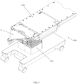
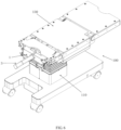
- FIGS. 5-7 are schematic diagrams of a surgical table according to an embodiment of the present disclosure.
- the surgical table 100 includes an upright column 110, and a surgical table extension unit mounted on the upright column 110.
- This surgical table extension unit is the surgical table extension unit shown in FIGS. 1-4 .
- the extension adapter 1 can be detachably connected with the upright column 110, and can be locked on the upright column 110.
- the upright column 110 can be extended and retracted along a vertical direction.
- a top end of the upright column 110 is provided with a bed body 130 for supporting a patient.
- the surgical table extension unit of the surgical table 100 shown in FIGS. 5-7 includes an extension adapter 1 and a support pad 2.
- the support pad 2 can be detachably connected with the extension adapter 1.
- the coupling structures of the support pad 2 and the extension adapter 1 are shown in FIGS. 1-4 and the above related description, and will not be repeated here.
- the support pad coupling mechanism of the present disclosure is simple in structure, easy to operate, and can effectively lower the cost.
Landscapes
- Health & Medical Sciences (AREA)
- Engineering & Computer Science (AREA)
- Biomedical Technology (AREA)
- Life Sciences & Earth Sciences (AREA)
- Animal Behavior & Ethology (AREA)
- General Health & Medical Sciences (AREA)
- Public Health (AREA)
- Veterinary Medicine (AREA)
- Accommodation For Nursing Or Treatment Tables (AREA)
Description
- The present disclosure relates to a surgical table, and more specifically relates to a support pad coupling mechanism for a surgical table extension unit, and a surgical table.
- A surgical table is a platform for performing surgical operations and is used to support a patient during surgical operations. During surgery, the surgical table needs to be adjusted to positions as needed in order to fully expose the surgical field of view. Most of the existing surgical tables adopt a modular design, and various modules can be selected according to needs so that diversified surgical requirements can be met. Some surgical tables are also equipped with an expansion unit, which can be easily expanded. The expansion unit generally includes a detachable support pad. However, existing support pad coupling mechanisms have complex structure and high cost problems.
-
US 2010/011504 A1 provides a guiding device for a mobile operating table comprising at least one lateral rail for accessories, the aforementioned device comprising at least one guiding arm stretching along an axis and presenting an extremity fitted with a fastening mechanism permitting a detachable fixing of the aforementioned guide arm on the rail of the operating table, characterized in that the fastening means consist of at least one notch oriented along an axis substantially perpendicular to the axis of the guiding arm, said notch being capable of accommodating a spacer linking the side rail to the operating table, and a blocking element configured to block the guide arm on the rail by pressure of the aforementioned blocking element. -
GB 2516109 A - One of the objects of the present disclosure is to provide a support pad coupling mechanism which is simple in structure and low in cost, and can help to lower the cost of surgical tables, and make the operation of a support pad simpler and more reliable.
- In a first aspect of the present application, there is provided a support pad coupling mechanism for a surgical table extension unit, the surgical table extension unit includes an extension adapter and a support pad. The support pad coupling mechanism comprises two coupling plates configured to be coupled to a lower side of the support pad so as to be perpendicular to the support pad. Each coupling plate is provided with a hook portion and a first position-limiting post. Each first position-limiting post extends along a direction perpendicular to a respective one of the coupling plates. The support pad coupling mechanism further comprises two second position-limiting posts configured to be provided on the extension adapter, the two second position-limiting posts respectively configured to cooperate with a respective hook portion, and two position-limiting recessed portions configured to be provided on the extension adapter, the two position-limiting recessed portions respectively configured to cooperate with a respective one of the first position-limiting posts. The two position-limiting recessed portions are in the shape of a circular arc. When the support pad and the extension adapter are coupled together by the support pad coupling mechanism, the first position-limiting posts of the coupling plates are positioned in the position-limiting recessed portions, and the hook portions of the coupling plates are hooked onto the second position-limiting posts.
- In another embodiment of the support pad coupling mechanism for a surgical table extension unit according to the present application, the coupling mechanism comprises two coupling portions configured to be provided on the extension adapter, the two coupling portions configured to cooperate with the two coupling plates respectively. Each of the coupling portions is provided with a cooperating face that cooperates with a respective one of the coupling plates. The second position-limiting posts may be provided on and perpendicular to the cooperating faces respectively. The position-limiting recessed portions may be formed on upper surfaces of the coupling portions respectively.
- In a further aspect of the present application, the present invention provides a surgical table extension unit comprising an extension adapter, a support pad, and a support pad coupling mechanism according to the first aspect of the present application.
- In another embodiment of the surgical table extension unit according to the present application, the two coupling plates of the support pad coupling mechanism are parallel to each other and are disposed close to one end of the support pad.
- In another embodiment of the surgical table extension unit according to the present application, the two coupling plates are disposed close to two side edges of the support pad respectively.
- In another embodiment of the surgical table extension unit according to the present application, the surgical table extension unit further includes an extension beam coupled with the extension adapter. The lower side of the support pad may be provided with a cushion block, and the cushion block may be provided with a groove that fits to the extension beam.
- One of the objects of the present disclosure is to also provide a surgical table. The surgical table is provided with the above-mentioned support pad coupling mechanism for a surgical table extension unit.
- The implementation of the support pad coupling mechanism for a surgical table extension unit and the surgical table of the present disclosure has the following beneficial effects: the support pad coupling mechanism of the present disclosure is simple in structure, easy to operate, and can effectively lower the cost.
- The present disclosure will be further explained below in conjunction with the embodiments and the drawings, wherein:
-
FIG. 1 is a schematic diagram showing the assembling of a support pad coupling mechanism for a surgical table extension unit according to an embodiment of the present disclosure; -
FIG. 2 is a schematic diagram of the support pad coupling mechanism for a surgical table extension unit, after assembly, according to an embodiment of the present disclosure; -
FIG. 3 is a schematic diagram showing a rear view of the support pad coupling mechanism for a surgical table extension unit according to an embodiment of the present disclosure; -
FIG. 4 is a schematic diagram showing a side view of the support pad coupling mechanism for a surgical table extension unit according to an embodiment of the present disclosure; -
FIG. 5 is a schematic perspective view of a surgical table according to an embodiment of the present disclosure; -
FIG. 6 is a schematic perspective view of the surgical table, shown inFIG. 5 , after the support pad is detached; and -
FIG. 7 is a partial enlarged view of the surgical table shown inFIG. 6 . - In order to have a clear understanding of the technical features, objectives, and advantages of the present disclosure, specific embodiments of the present disclosure will be described in detail below with reference to the accompanying drawings.
- The embodiments of the support pad coupling mechanism for a surgical table extension unit and the surgical table of the present disclosure are described below in detail. Examples of these embodiments are shown in the accompanying drawings. The same or similar reference numeral denotes the same or similar elements, or elements having the same or similar function throughout the specification.
- In the description of the support pad coupling mechanism for a surgical table extension unit and the surgical table of the present disclosure, it should be understood that the terms "front", "rear", "upper", "lower", "upper end", "lower end", "upper portion", "lower portion", etc. indicate spatial relationship that is based on the orientation or positional relationship shown in the drawings, and are only used for the convenience of describing the present disclosure and simplifying the description, rather than indicating or implying that the device or element referred to must have a specific orientation and be constructed and operated in a specific orientation. Therefore, these terms cannot be understood as a limitation to the present disclosure. In addition, the terms "first" and "second" are used for descriptive purposes only, and cannot be understood as indicating or implying relative importance.
-
FIGS. 1-4 are schematic diagrams of a support pad coupling mechanism for a surgical table extension unit according to an embodiment of the present disclosure. In the present embodiment, the surgical table extension unit includes anextension adapter 1 and asupport pad 2. The surgical table extension unit is used for extending the function of the surgical table. Certain functional components may be added on the surgical table extension unit to satisfy surgical needs. Thesupport pad 2 may be detachably connected with theextension adapter 1. Theextension adapter 1 may be connected with an upright column (not shown) of the surgical table. - Referring to
FIGS. 1-4 , a lower side of thesupport pad 2 is provided with twocoupling plates 20 that are perpendicular to thesupport pad 2. Thecoupling plates 20 can be mounted on thesupport pad 2 using various types of mechanical fasteners (for example, screws, bolts, rivets, etc.) and/or bonding part (for example, thermal bonding part, welding). Eachcoupling plate 20 is provided with ahook portion 21 and a first position-limitingpost 22. Each first position-limitingpost 22 extends along a direction perpendicular to a respective one of thecoupling plates 20. The first position-limitingposts 22 can be mounted on thecoupling plates 20 by screw threads, or welding, or any other appropriate method. The twocoupling plates 20 may be parallel to each other and disposed close to one end of thesupport pad 2. The twocoupling plates 20 may be disposed close to two side edges of thesupport pad 2 respectively. - Referring to
FIGS. 1-4 , theextension adapter 1 is provided with two second position-limitingposts 12 that respectively cooperate with arespective hook portion 21, and two position-limiting recessedportions 13 that respectively cooperate with a respective first position-limitingpost 22. When thesupport pad 2 and theextension adapter 1 are coupled together, the first position-limitingposts 22 of thecoupling plates 20 are positioned in the position-limiting recessedportions 13, and thehook portions 21 of thecoupling plates 20 are hooked onto the second position-limitingposts 12. Specifically, in the present embodiment, theextension adapter 1 includes twocoupling portions 10 that cooperate with the twocoupling plates 20 respectively. Each of thecoupling portions 10 may be provided with a cooperatingface 11 that cooperates with a respective one of thecoupling plates 20. The second position-limitingposts 12 are provided on and perpendicular to the cooperating faces 11 respectively. The second position-limitingposts 12 can be connected on the cooperating faces 11 by screw threads, or welding, or any other appropriate method. The position-limiting recessedportions 13 are formed onupper surfaces 14 of thecoupling portions 10 respectively. The position-limiting recessedportions 13 may be in the shape of a circular arc. - Referring to
FIG. 1 , when attaching thesupport pad 2 to theextension adapter 1, thesupport pad 2 is placed on theextension adapter 1 at an angle. The two first position-limitingposts 22 of the twocoupling plates 20 of thesupport pad 2 are first put into the two position-limiting recessedportions 13 of the twocoupling portions 10 of theextension adapter 1. Thesupport pad 2 is then placed horizontally so that thehook portions 21 of the twocoupling plates 20 are hooked onto the two second position-limitingposts 12, thereby attaching thesupport pad 2 on theextension adapter 1. To detach thesupport pad 2 from theextension adapter 1, a reverse order of the attaching procedure can be carried out. - Referring to
FIGS. 1 and3 , the surgical table extension unit further includes anextension beam 3 that is coupled with theextension adapter 1. Theextension beam 3 extends outwardly from theextension adapter 1. Theextension beam 3 can be used for mounting thereon extension components in order to satisfy certain functional needs. The lower side of thesupport pad 2 may be provided with acushion block 23, and thecushion block 23 may be provided with agroove 231 that fits to theextension beam 3. When thesupport pad 2 is mounted on theextension adapter 1, theextension beam 3 is located in thegroove 231 such that thesupport pad 2 can have a better support and can be more stable. -
FIGS. 5-7 are schematic diagrams of a surgical table according to an embodiment of the present disclosure. In this embodiment, the surgical table 100 includes anupright column 110, and a surgical table extension unit mounted on theupright column 110. This surgical table extension unit is the surgical table extension unit shown inFIGS. 1-4 . In the present embodiment, theextension adapter 1 can be detachably connected with theupright column 110, and can be locked on theupright column 110. Theupright column 110 can be extended and retracted along a vertical direction. A top end of theupright column 110 is provided with abed body 130 for supporting a patient. The surgical table extension unit of the surgical table 100 shown inFIGS. 5-7 includes anextension adapter 1 and asupport pad 2. Thesupport pad 2 can be detachably connected with theextension adapter 1. The coupling structures of thesupport pad 2 and theextension adapter 1 are shown inFIGS. 1-4 and the above related description, and will not be repeated here. - The support pad coupling mechanism of the present disclosure is simple in structure, easy to operate, and can effectively lower the cost.
- The embodiments of the present disclosure are described above with reference to the accompanying drawings. However, the present disclosure is not limited to the above-mentioned specific embodiments. The above-mentioned specific embodiments are only illustrative and not restrictive. Under the enlightenment of the present disclosure, a person of ordinary skill in the art can make many forms, without departing from the purpose of the present disclosure and the scope of protection of the claims, and all of these forms shall fall within the protection of the present disclosure.
Claims (15)
- A support pad coupling mechanism for a surgical table extension unit, the surgical table extension unit including an extension adapter (1) and a support pad (2), the coupling mechanism comprising:two coupling plates (20) configured to be coupled to a lower side of the support pad (2) so as to be perpendicular to the support pad (2),
wherein each coupling plate (20) is provided with a hook portion (21) and a first position-limiting post (22), each first position-limiting post (22) extending along a direction perpendicular to a respective one of the coupling plates (20);two second position-limiting posts (12) configured to be provided on the extension adapter (1), the two second position-limiting posts (12) respectively configured to cooperate with a respective one of the hook portions (21); andtwo position-limiting recessed portions (13) configured to be provided on the extension adapter (1), the two position-limiting recessed portions (13) respectively configured to cooperate with a respective one of the first position-limiting posts (22), wherein the two position-limiting recessed portions (13) are in a shape of a circular arc,
wherein, when the support pad (2) and the extension adapter (1) are coupled together by the support pad coupling mechanism, the first position-limiting posts (22) of the coupling plates (20) are positioned in the two position-limiting recessed portions (13), and the hook portions (21) of the coupling plates (20) are hooked onto the two second position-limiting posts (12). - The support pad coupling mechanism for a surgical table extension unit according to claim 1, comprising two coupling portions (10) configured to be provided on the extension adapter (1), the two coupling portions (10) configured to cooperate with the two coupling plates (20) respectively, each of the coupling portions (10) being provided with a cooperating face (11) that cooperates with a respective one of the coupling plates (20).
- The support pad coupling mechanism for a surgical table extension unit according to claim 2, characterized in that the two second position-limiting posts (12) are provided on, and perpendicular to, the cooperating faces (11) respectively.
- The support pad coupling mechanism for a surgical table extension unit according to claim 2 or 3, characterized in that the two position-limiting recessed portions (13) are formed on upper surfaces (14) of the two coupling portions (10) respectively.
- A surgical table extension unit comprising:an extension adapter (1);a support pad (2); anda support pad coupling mechanism according to any of claims 1 to 4.
- The surgical table extension unit according to claim 5, wherein the two coupling plates (20) of the support pad coupling mechanism are parallel to each other and are disposed close to one end of the support pad (2).
- The surgical table extension unit according to claim 5 or 6, characterized in that the two coupling plates (20) are disposed close to two side edges of the support pad (2) respectively.
- The surgical table extension unit according to any one of claims 5 to 7, characterized in that the support pad (2) is detachably connected with the extension adapter (1).
- The surgical table extension unit according to any one of claims 5 to 8, characterized in that the surgical table extension unit further comprises an extension beam (3) coupled with the extension adapter (1) for supporting the support pad (2).
- The surgical table extension unit according to claim 9, characterized in that the lower side of the support pad (2) is provided with a cushion block (23).
- The surgical table extension unit according to claim 10, characterized in that the cushion block (23) is provided with a groove (231) that fits to the extension beam (3).
- The surgical table extension unit according to any one of claims 9 to 11, characterized in that the extension beam (3) extends outwardly from the extension adapter (1).
- The surgical table extension unit according to any one of claims 5 to 12, characterized in that the coupling plates (20) are mounted on the support pad (2) by thermal bonding.
- The surgical table extension unit according to any one of claims 5 to 12, characterized in that the coupling plates (20) are mounted on the support pad (2) by welding.
- The support pad coupling mechanism according to anyone of claims 1 to 4 or a surgical table extension unit according to any one of claims 5 to 14, characterized in that the first position-limiting posts (22) are mounted on the coupling plates (20) by welding.
Applications Claiming Priority (1)
| Application Number | Priority Date | Filing Date | Title |
|---|---|---|---|
| CN201921893872.XU CN211356501U (en) | 2019-11-05 | 2019-11-05 | Supporting plate connecting device of operating table extension unit and operating table |
Publications (2)
| Publication Number | Publication Date |
|---|---|
| EP3818970A1 EP3818970A1 (en) | 2021-05-12 |
| EP3818970B1 true EP3818970B1 (en) | 2023-05-03 |
Family
ID=72158674
Family Applications (1)
| Application Number | Title | Priority Date | Filing Date |
|---|---|---|---|
| EP20203102.7A Active EP3818970B1 (en) | 2019-11-05 | 2020-10-21 | Support pad coupling mechanism for surgical table extension unit, and surgical table |
Country Status (3)
| Country | Link |
|---|---|
| US (1) | US12036157B2 (en) |
| EP (1) | EP3818970B1 (en) |
| CN (1) | CN211356501U (en) |
Family Cites Families (17)
| Publication number | Priority date | Publication date | Assignee | Title |
|---|---|---|---|---|
| US2638606A (en) * | 1948-07-13 | 1953-05-19 | Dwight E Austin | Bed bottom |
| US2717593A (en) * | 1952-08-22 | 1955-09-13 | Owen K Murphy | Table type of motor operated kinesitherapy device |
| US3732860A (en) * | 1971-07-21 | 1973-05-15 | G Thurmer | Vibrating massage device |
| US4077664A (en) * | 1974-12-16 | 1978-03-07 | Coach And Car Equipment Corporation | Seat with cushioned grab bar |
| US5103513A (en) * | 1988-08-25 | 1992-04-14 | King E Autry | Magnetic-cushioned support for bed or seat |
| US6754923B2 (en) * | 1997-11-07 | 2004-06-29 | Hill-Rom Services, Inc. | Leg section support for a surgical table |
| BR9916131A (en) | 1998-12-11 | 2001-11-06 | Hill Rom Co Inc | Bed mounts, patient support for an articulated bed and articulated push handle for hospital beds, and hospital bed |
| DE20009875U1 (en) | 2000-06-02 | 2000-10-26 | Schindler, Rolf, Dr., 97424 Schweinfurt | Positioning aid for tomographic functional examination of the cervical spine |
| DE102005054174A1 (en) | 2005-11-14 | 2007-05-16 | Maquet Gmbh & Co Kg | Patient storage area for an operating table |
| DE102005054175A1 (en) | 2005-11-14 | 2007-05-16 | Maquet Gmbh & Co Kg | Joint arrangement for connecting two segments of a patient support surface |
| FR2901122B1 (en) * | 2006-05-18 | 2008-08-22 | Steris Surgical Technologies Sas | GUIDE DEVICE FOR OPERATING TABLE COMPRISING GUIDING ARMS SUITABLE TO BE FIXED REMOVABLY ON THE TABLE, AND OPERATING TABLE COMPRISING SUCH GUIDING ARMS |
| DK177246B1 (en) | 2008-06-27 | 2012-08-06 | Guldmann V As | Clutch |
| KR101332637B1 (en) * | 2011-11-09 | 2013-11-25 | 제이더블유중외메디칼 주식회사 | Separation type bed |
| US8997281B2 (en) * | 2012-03-23 | 2015-04-07 | Trumpf Medizin Systeme Gmbh + Co. Kg | Operating table top assemblies and related devices |
| US9730851B2 (en) * | 2012-09-07 | 2017-08-15 | Allen Medical Systems, Inc. | Surgical support system |
| GB2535054B (en) | 2013-07-12 | 2017-01-11 | Eschmann Holdings Ltd | Tabletop sections for surgical tables |
| US10267350B2 (en) | 2015-08-12 | 2019-04-23 | Semler Technologies, Inc. | Integrated armboard and wrist support apparatuses and methods of use |
-
2019
- 2019-11-05 CN CN201921893872.XU patent/CN211356501U/en active Active
-
2020
- 2020-10-21 EP EP20203102.7A patent/EP3818970B1/en active Active
- 2020-11-05 US US17/090,507 patent/US12036157B2/en active Active
Also Published As
| Publication number | Publication date |
|---|---|
| EP3818970A1 (en) | 2021-05-12 |
| US12036157B2 (en) | 2024-07-16 |
| CN211356501U (en) | 2020-08-28 |
| US20210128385A1 (en) | 2021-05-06 |
Similar Documents
| Publication | Publication Date | Title |
|---|---|---|
| US9476575B2 (en) | Video display module support assembly | |
| US9894988B2 (en) | Stand for supporting a computing device | |
| KR20110035971A (en) | Wall mount | |
| US20050005356A1 (en) | Radiotherapy treatment and imaging patient support table | |
| JP2005521535A (en) | Operating table transfer system | |
| JP2018161461A (en) | Bracket and slide rail assembly using the same | |
| KR101948743B1 (en) | Joint Assembly For Connecting A Long Extension Panel To A Patient Support Panel Of A Radiation Therapy Table And A Two-Piece Patient Support Table Formed Thereby | |
| EP3958812B1 (en) | Shoulder hold-down and locking mechanism therefor for use with a surgical frame | |
| CN218383625U (en) | Lens adjustment mechanism and projection equipment | |
| EP3818970A1 (en) | Support pad coupling mechanism for surgical table extension unit, and surgical table | |
| JP2019126358A (en) | Fixing device | |
| CN119344819B (en) | Osteotomy tools | |
| TW202539547A (en) | Slide rail assembly | |
| US4640346A (en) | Tube lane manipulator for the high-pressure blow-down of heat exchangers | |
| CN222899595U (en) | Quick detach mechanism and operating table | |
| CN114431926A (en) | Lithotripsy equipment treatment bed | |
| CN221490241U (en) | Supporting device and interventional medical system | |
| CN215688403U (en) | Minimally invasive surgery doctor operating table handrail and minimally invasive surgery doctor operating table | |
| US20100064442A1 (en) | Patient load support for use with elongate beds | |
| CN111096550B (en) | Table (Table) | |
| KR102539632B1 (en) | The top board combination structure of table | |
| CN214404206U (en) | A positioning combined metal part | |
| CN216464737U (en) | Quick change robot calibration tooling | |
| CN223687516U (en) | Turnover device | |
| JP4057272B2 (en) | Furniture system |
Legal Events
| Date | Code | Title | Description |
|---|---|---|---|
| PUAI | Public reference made under article 153(3) epc to a published international application that has entered the european phase |
Free format text: ORIGINAL CODE: 0009012 |
|
| STAA | Information on the status of an ep patent application or granted ep patent |
Free format text: STATUS: THE APPLICATION HAS BEEN PUBLISHED |
|
| AK | Designated contracting states |
Kind code of ref document: A1 Designated state(s): AL AT BE BG CH CY CZ DE DK EE ES FI FR GB GR HR HU IE IS IT LI LT LU LV MC MK MT NL NO PL PT RO RS SE SI SK SM TR |
|
| STAA | Information on the status of an ep patent application or granted ep patent |
Free format text: STATUS: REQUEST FOR EXAMINATION WAS MADE |
|
| 17P | Request for examination filed |
Effective date: 20211112 |
|
| RBV | Designated contracting states (corrected) |
Designated state(s): AL AT BE BG CH CY CZ DE DK EE ES FI FR GB GR HR HU IE IS IT LI LT LU LV MC MK MT NL NO PL PT RO RS SE SI SK SM TR |
|
| GRAP | Despatch of communication of intention to grant a patent |
Free format text: ORIGINAL CODE: EPIDOSNIGR1 |
|
| STAA | Information on the status of an ep patent application or granted ep patent |
Free format text: STATUS: GRANT OF PATENT IS INTENDED |
|
| INTG | Intention to grant announced |
Effective date: 20221124 |
|
| GRAS | Grant fee paid |
Free format text: ORIGINAL CODE: EPIDOSNIGR3 |
|
| GRAA | (expected) grant |
Free format text: ORIGINAL CODE: 0009210 |
|
| STAA | Information on the status of an ep patent application or granted ep patent |
Free format text: STATUS: THE PATENT HAS BEEN GRANTED |
|
| RAP3 | Party data changed (applicant data changed or rights of an application transferred) |
Owner name: BAXTER MEDICAL SYSTEMS GMBH + CO. KG |
|
| AK | Designated contracting states |
Kind code of ref document: B1 Designated state(s): AL AT BE BG CH CY CZ DE DK EE ES FI FR GB GR HR HU IE IS IT LI LT LU LV MC MK MT NL NO PL PT RO RS SE SI SK SM TR |
|
| REG | Reference to a national code |
Ref country code: GB Ref legal event code: FG4D |
|
| REG | Reference to a national code |
Ref country code: DE Ref legal event code: R096 Ref document number: 602020010354 Country of ref document: DE |
|
| REG | Reference to a national code |
Ref country code: AT Ref legal event code: REF Ref document number: 1563979 Country of ref document: AT Kind code of ref document: T Effective date: 20230515 Ref country code: CH Ref legal event code: EP |
|
| REG | Reference to a national code |
Ref country code: IE Ref legal event code: FG4D |
|
| REG | Reference to a national code |
Ref country code: LT Ref legal event code: MG9D |
|
| REG | Reference to a national code |
Ref country code: NL Ref legal event code: MP Effective date: 20230503 |
|
| REG | Reference to a national code |
Ref country code: AT Ref legal event code: MK05 Ref document number: 1563979 Country of ref document: AT Kind code of ref document: T Effective date: 20230503 |
|
| PG25 | Lapsed in a contracting state [announced via postgrant information from national office to epo] |
Ref country code: SE Free format text: LAPSE BECAUSE OF FAILURE TO SUBMIT A TRANSLATION OF THE DESCRIPTION OR TO PAY THE FEE WITHIN THE PRESCRIBED TIME-LIMIT Effective date: 20230503 Ref country code: PT Free format text: LAPSE BECAUSE OF FAILURE TO SUBMIT A TRANSLATION OF THE DESCRIPTION OR TO PAY THE FEE WITHIN THE PRESCRIBED TIME-LIMIT Effective date: 20230904 Ref country code: NO Free format text: LAPSE BECAUSE OF FAILURE TO SUBMIT A TRANSLATION OF THE DESCRIPTION OR TO PAY THE FEE WITHIN THE PRESCRIBED TIME-LIMIT Effective date: 20230803 Ref country code: NL Free format text: LAPSE BECAUSE OF FAILURE TO SUBMIT A TRANSLATION OF THE DESCRIPTION OR TO PAY THE FEE WITHIN THE PRESCRIBED TIME-LIMIT Effective date: 20230503 Ref country code: ES Free format text: LAPSE BECAUSE OF FAILURE TO SUBMIT A TRANSLATION OF THE DESCRIPTION OR TO PAY THE FEE WITHIN THE PRESCRIBED TIME-LIMIT Effective date: 20230503 Ref country code: AT Free format text: LAPSE BECAUSE OF FAILURE TO SUBMIT A TRANSLATION OF THE DESCRIPTION OR TO PAY THE FEE WITHIN THE PRESCRIBED TIME-LIMIT Effective date: 20230503 |
|
| PG25 | Lapsed in a contracting state [announced via postgrant information from national office to epo] |
Ref country code: RS Free format text: LAPSE BECAUSE OF FAILURE TO SUBMIT A TRANSLATION OF THE DESCRIPTION OR TO PAY THE FEE WITHIN THE PRESCRIBED TIME-LIMIT Effective date: 20230503 Ref country code: PL Free format text: LAPSE BECAUSE OF FAILURE TO SUBMIT A TRANSLATION OF THE DESCRIPTION OR TO PAY THE FEE WITHIN THE PRESCRIBED TIME-LIMIT Effective date: 20230503 Ref country code: LV Free format text: LAPSE BECAUSE OF FAILURE TO SUBMIT A TRANSLATION OF THE DESCRIPTION OR TO PAY THE FEE WITHIN THE PRESCRIBED TIME-LIMIT Effective date: 20230503 Ref country code: LT Free format text: LAPSE BECAUSE OF FAILURE TO SUBMIT A TRANSLATION OF THE DESCRIPTION OR TO PAY THE FEE WITHIN THE PRESCRIBED TIME-LIMIT Effective date: 20230503 Ref country code: IS Free format text: LAPSE BECAUSE OF FAILURE TO SUBMIT A TRANSLATION OF THE DESCRIPTION OR TO PAY THE FEE WITHIN THE PRESCRIBED TIME-LIMIT Effective date: 20230903 Ref country code: HR Free format text: LAPSE BECAUSE OF FAILURE TO SUBMIT A TRANSLATION OF THE DESCRIPTION OR TO PAY THE FEE WITHIN THE PRESCRIBED TIME-LIMIT Effective date: 20230503 Ref country code: GR Free format text: LAPSE BECAUSE OF FAILURE TO SUBMIT A TRANSLATION OF THE DESCRIPTION OR TO PAY THE FEE WITHIN THE PRESCRIBED TIME-LIMIT Effective date: 20230804 |
|
| PG25 | Lapsed in a contracting state [announced via postgrant information from national office to epo] |
Ref country code: FI Free format text: LAPSE BECAUSE OF FAILURE TO SUBMIT A TRANSLATION OF THE DESCRIPTION OR TO PAY THE FEE WITHIN THE PRESCRIBED TIME-LIMIT Effective date: 20230503 |
|
| PG25 | Lapsed in a contracting state [announced via postgrant information from national office to epo] |
Ref country code: SK Free format text: LAPSE BECAUSE OF FAILURE TO SUBMIT A TRANSLATION OF THE DESCRIPTION OR TO PAY THE FEE WITHIN THE PRESCRIBED TIME-LIMIT Effective date: 20230503 |
|
| PG25 | Lapsed in a contracting state [announced via postgrant information from national office to epo] |
Ref country code: SM Free format text: LAPSE BECAUSE OF FAILURE TO SUBMIT A TRANSLATION OF THE DESCRIPTION OR TO PAY THE FEE WITHIN THE PRESCRIBED TIME-LIMIT Effective date: 20230503 Ref country code: SK Free format text: LAPSE BECAUSE OF FAILURE TO SUBMIT A TRANSLATION OF THE DESCRIPTION OR TO PAY THE FEE WITHIN THE PRESCRIBED TIME-LIMIT Effective date: 20230503 Ref country code: RO Free format text: LAPSE BECAUSE OF FAILURE TO SUBMIT A TRANSLATION OF THE DESCRIPTION OR TO PAY THE FEE WITHIN THE PRESCRIBED TIME-LIMIT Effective date: 20230503 Ref country code: EE Free format text: LAPSE BECAUSE OF FAILURE TO SUBMIT A TRANSLATION OF THE DESCRIPTION OR TO PAY THE FEE WITHIN THE PRESCRIBED TIME-LIMIT Effective date: 20230503 Ref country code: DK Free format text: LAPSE BECAUSE OF FAILURE TO SUBMIT A TRANSLATION OF THE DESCRIPTION OR TO PAY THE FEE WITHIN THE PRESCRIBED TIME-LIMIT Effective date: 20230503 Ref country code: CZ Free format text: LAPSE BECAUSE OF FAILURE TO SUBMIT A TRANSLATION OF THE DESCRIPTION OR TO PAY THE FEE WITHIN THE PRESCRIBED TIME-LIMIT Effective date: 20230503 |
|
| REG | Reference to a national code |
Ref country code: DE Ref legal event code: R097 Ref document number: 602020010354 Country of ref document: DE |
|
| PLBE | No opposition filed within time limit |
Free format text: ORIGINAL CODE: 0009261 |
|
| STAA | Information on the status of an ep patent application or granted ep patent |
Free format text: STATUS: NO OPPOSITION FILED WITHIN TIME LIMIT |
|
| 26N | No opposition filed |
Effective date: 20240206 |
|
| PG25 | Lapsed in a contracting state [announced via postgrant information from national office to epo] |
Ref country code: SI Free format text: LAPSE BECAUSE OF FAILURE TO SUBMIT A TRANSLATION OF THE DESCRIPTION OR TO PAY THE FEE WITHIN THE PRESCRIBED TIME-LIMIT Effective date: 20230503 |
|
| PG25 | Lapsed in a contracting state [announced via postgrant information from national office to epo] |
Ref country code: SI Free format text: LAPSE BECAUSE OF FAILURE TO SUBMIT A TRANSLATION OF THE DESCRIPTION OR TO PAY THE FEE WITHIN THE PRESCRIBED TIME-LIMIT Effective date: 20230503 Ref country code: IT Free format text: LAPSE BECAUSE OF FAILURE TO SUBMIT A TRANSLATION OF THE DESCRIPTION OR TO PAY THE FEE WITHIN THE PRESCRIBED TIME-LIMIT Effective date: 20230503 Ref country code: MC Free format text: LAPSE BECAUSE OF FAILURE TO SUBMIT A TRANSLATION OF THE DESCRIPTION OR TO PAY THE FEE WITHIN THE PRESCRIBED TIME-LIMIT Effective date: 20230503 |
|
| REG | Reference to a national code |
Ref country code: CH Ref legal event code: PL |
|
| REG | Reference to a national code |
Ref country code: BE Ref legal event code: MM Effective date: 20231031 |
|
| PG25 | Lapsed in a contracting state [announced via postgrant information from national office to epo] |
Ref country code: LU Free format text: LAPSE BECAUSE OF NON-PAYMENT OF DUE FEES Effective date: 20231021 |
|
| PG25 | Lapsed in a contracting state [announced via postgrant information from national office to epo] |
Ref country code: LU Free format text: LAPSE BECAUSE OF NON-PAYMENT OF DUE FEES Effective date: 20231021 |
|
| PG25 | Lapsed in a contracting state [announced via postgrant information from national office to epo] |
Ref country code: CH Free format text: LAPSE BECAUSE OF NON-PAYMENT OF DUE FEES Effective date: 20231031 |
|
| PG25 | Lapsed in a contracting state [announced via postgrant information from national office to epo] |
Ref country code: CH Free format text: LAPSE BECAUSE OF NON-PAYMENT OF DUE FEES Effective date: 20231031 |
|
| PG25 | Lapsed in a contracting state [announced via postgrant information from national office to epo] |
Ref country code: BE Free format text: LAPSE BECAUSE OF NON-PAYMENT OF DUE FEES Effective date: 20231031 |
|
| PG25 | Lapsed in a contracting state [announced via postgrant information from national office to epo] |
Ref country code: IE Free format text: LAPSE BECAUSE OF NON-PAYMENT OF DUE FEES Effective date: 20231021 |
|
| PG25 | Lapsed in a contracting state [announced via postgrant information from national office to epo] |
Ref country code: IE Free format text: LAPSE BECAUSE OF NON-PAYMENT OF DUE FEES Effective date: 20231021 |
|
| PG25 | Lapsed in a contracting state [announced via postgrant information from national office to epo] |
Ref country code: BG Free format text: LAPSE BECAUSE OF FAILURE TO SUBMIT A TRANSLATION OF THE DESCRIPTION OR TO PAY THE FEE WITHIN THE PRESCRIBED TIME-LIMIT Effective date: 20230503 |
|
| PG25 | Lapsed in a contracting state [announced via postgrant information from national office to epo] |
Ref country code: BG Free format text: LAPSE BECAUSE OF FAILURE TO SUBMIT A TRANSLATION OF THE DESCRIPTION OR TO PAY THE FEE WITHIN THE PRESCRIBED TIME-LIMIT Effective date: 20230503 |
|
| PG25 | Lapsed in a contracting state [announced via postgrant information from national office to epo] |
Ref country code: CY Free format text: LAPSE BECAUSE OF FAILURE TO SUBMIT A TRANSLATION OF THE DESCRIPTION OR TO PAY THE FEE WITHIN THE PRESCRIBED TIME-LIMIT; INVALID AB INITIO Effective date: 20201021 |
|
| PG25 | Lapsed in a contracting state [announced via postgrant information from national office to epo] |
Ref country code: HU Free format text: LAPSE BECAUSE OF FAILURE TO SUBMIT A TRANSLATION OF THE DESCRIPTION OR TO PAY THE FEE WITHIN THE PRESCRIBED TIME-LIMIT; INVALID AB INITIO Effective date: 20201021 |
|
| PGFP | Annual fee paid to national office [announced via postgrant information from national office to epo] |
Ref country code: GB Payment date: 20250923 Year of fee payment: 6 |
|
| PGFP | Annual fee paid to national office [announced via postgrant information from national office to epo] |
Ref country code: FR Payment date: 20250924 Year of fee payment: 6 |
|
| PG25 | Lapsed in a contracting state [announced via postgrant information from national office to epo] |
Ref country code: TR Free format text: LAPSE BECAUSE OF FAILURE TO SUBMIT A TRANSLATION OF THE DESCRIPTION OR TO PAY THE FEE WITHIN THE PRESCRIBED TIME-LIMIT Effective date: 20230503 |
|
| PGFP | Annual fee paid to national office [announced via postgrant information from national office to epo] |
Ref country code: DE Payment date: 20250923 Year of fee payment: 6 |