EP3818965A1 - Spinal intervertebral body fusion device - Google Patents
Spinal intervertebral body fusion device Download PDFInfo
- Publication number
- EP3818965A1 EP3818965A1 EP19219449.6A EP19219449A EP3818965A1 EP 3818965 A1 EP3818965 A1 EP 3818965A1 EP 19219449 A EP19219449 A EP 19219449A EP 3818965 A1 EP3818965 A1 EP 3818965A1
- Authority
- EP
- European Patent Office
- Prior art keywords
- supporting plate
- plate portion
- piece
- fusion device
- pushing piece
- Prior art date
- Legal status (The legal status is an assumption and is not a legal conclusion. Google has not performed a legal analysis and makes no representation as to the accuracy of the status listed.)
- Granted
Links
Images








Classifications
-
- A—HUMAN NECESSITIES
- A61—MEDICAL OR VETERINARY SCIENCE; HYGIENE
- A61F—FILTERS IMPLANTABLE INTO BLOOD VESSELS; PROSTHESES; DEVICES PROVIDING PATENCY TO, OR PREVENTING COLLAPSING OF, TUBULAR STRUCTURES OF THE BODY, e.g. STENTS; ORTHOPAEDIC, NURSING OR CONTRACEPTIVE DEVICES; FOMENTATION; TREATMENT OR PROTECTION OF EYES OR EARS; BANDAGES, DRESSINGS OR ABSORBENT PADS; FIRST-AID KITS
- A61F2/00—Filters implantable into blood vessels; Prostheses, i.e. artificial substitutes or replacements for parts of the body; Appliances for connecting them with the body; Devices providing patency to, or preventing collapsing of, tubular structures of the body, e.g. stents
- A61F2/02—Prostheses implantable into the body
- A61F2/30—Joints
- A61F2/44—Joints for the spine, e.g. vertebrae, spinal discs
- A61F2/4455—Joints for the spine, e.g. vertebrae, spinal discs for the fusion of spinal bodies, e.g. intervertebral fusion of adjacent spinal bodies, e.g. fusion cages
-
- A—HUMAN NECESSITIES
- A61—MEDICAL OR VETERINARY SCIENCE; HYGIENE
- A61F—FILTERS IMPLANTABLE INTO BLOOD VESSELS; PROSTHESES; DEVICES PROVIDING PATENCY TO, OR PREVENTING COLLAPSING OF, TUBULAR STRUCTURES OF THE BODY, e.g. STENTS; ORTHOPAEDIC, NURSING OR CONTRACEPTIVE DEVICES; FOMENTATION; TREATMENT OR PROTECTION OF EYES OR EARS; BANDAGES, DRESSINGS OR ABSORBENT PADS; FIRST-AID KITS
- A61F2/00—Filters implantable into blood vessels; Prostheses, i.e. artificial substitutes or replacements for parts of the body; Appliances for connecting them with the body; Devices providing patency to, or preventing collapsing of, tubular structures of the body, e.g. stents
- A61F2/02—Prostheses implantable into the body
- A61F2/30—Joints
- A61F2/30721—Accessories
- A61F2/30724—Spacers for centering an implant in a bone cavity, e.g. in a cement-receiving cavity
-
- A—HUMAN NECESSITIES
- A61—MEDICAL OR VETERINARY SCIENCE; HYGIENE
- A61F—FILTERS IMPLANTABLE INTO BLOOD VESSELS; PROSTHESES; DEVICES PROVIDING PATENCY TO, OR PREVENTING COLLAPSING OF, TUBULAR STRUCTURES OF THE BODY, e.g. STENTS; ORTHOPAEDIC, NURSING OR CONTRACEPTIVE DEVICES; FOMENTATION; TREATMENT OR PROTECTION OF EYES OR EARS; BANDAGES, DRESSINGS OR ABSORBENT PADS; FIRST-AID KITS
- A61F2/00—Filters implantable into blood vessels; Prostheses, i.e. artificial substitutes or replacements for parts of the body; Appliances for connecting them with the body; Devices providing patency to, or preventing collapsing of, tubular structures of the body, e.g. stents
- A61F2/02—Prostheses implantable into the body
- A61F2/30—Joints
- A61F2/3094—Designing or manufacturing processes
- A61F2/30942—Designing or manufacturing processes for designing or making customized prostheses, e.g. using templates, CT or NMR scans, finite-element analysis or CAD-CAM techniques
-
- A—HUMAN NECESSITIES
- A61—MEDICAL OR VETERINARY SCIENCE; HYGIENE
- A61F—FILTERS IMPLANTABLE INTO BLOOD VESSELS; PROSTHESES; DEVICES PROVIDING PATENCY TO, OR PREVENTING COLLAPSING OF, TUBULAR STRUCTURES OF THE BODY, e.g. STENTS; ORTHOPAEDIC, NURSING OR CONTRACEPTIVE DEVICES; FOMENTATION; TREATMENT OR PROTECTION OF EYES OR EARS; BANDAGES, DRESSINGS OR ABSORBENT PADS; FIRST-AID KITS
- A61F2/00—Filters implantable into blood vessels; Prostheses, i.e. artificial substitutes or replacements for parts of the body; Appliances for connecting them with the body; Devices providing patency to, or preventing collapsing of, tubular structures of the body, e.g. stents
- A61F2/02—Prostheses implantable into the body
- A61F2/30—Joints
- A61F2/44—Joints for the spine, e.g. vertebrae, spinal discs
- A61F2/4455—Joints for the spine, e.g. vertebrae, spinal discs for the fusion of spinal bodies, e.g. intervertebral fusion of adjacent spinal bodies, e.g. fusion cages
- A61F2/447—Joints for the spine, e.g. vertebrae, spinal discs for the fusion of spinal bodies, e.g. intervertebral fusion of adjacent spinal bodies, e.g. fusion cages substantially parallelepipedal, e.g. having a rectangular or trapezoidal cross-section
-
- A—HUMAN NECESSITIES
- A61—MEDICAL OR VETERINARY SCIENCE; HYGIENE
- A61F—FILTERS IMPLANTABLE INTO BLOOD VESSELS; PROSTHESES; DEVICES PROVIDING PATENCY TO, OR PREVENTING COLLAPSING OF, TUBULAR STRUCTURES OF THE BODY, e.g. STENTS; ORTHOPAEDIC, NURSING OR CONTRACEPTIVE DEVICES; FOMENTATION; TREATMENT OR PROTECTION OF EYES OR EARS; BANDAGES, DRESSINGS OR ABSORBENT PADS; FIRST-AID KITS
- A61F2/00—Filters implantable into blood vessels; Prostheses, i.e. artificial substitutes or replacements for parts of the body; Appliances for connecting them with the body; Devices providing patency to, or preventing collapsing of, tubular structures of the body, e.g. stents
- A61F2/02—Prostheses implantable into the body
- A61F2/30—Joints
- A61F2002/30001—Additional features of subject-matter classified in A61F2/28, A61F2/30 and subgroups thereof
- A61F2002/30316—The prosthesis having different structural features at different locations within the same prosthesis; Connections between prosthetic parts; Special structural features of bone or joint prostheses not otherwise provided for
- A61F2002/30329—Connections or couplings between prosthetic parts, e.g. between modular parts; Connecting elements
- A61F2002/30383—Connections or couplings between prosthetic parts, e.g. between modular parts; Connecting elements made by laterally inserting a protrusion, e.g. a rib into a complementarily-shaped groove
- A61F2002/3039—Connections or couplings between prosthetic parts, e.g. between modular parts; Connecting elements made by laterally inserting a protrusion, e.g. a rib into a complementarily-shaped groove with possibility of relative movement of the rib within the groove
- A61F2002/30398—Sliding
- A61F2002/304—Sliding with additional means for limiting said sliding
-
- A—HUMAN NECESSITIES
- A61—MEDICAL OR VETERINARY SCIENCE; HYGIENE
- A61F—FILTERS IMPLANTABLE INTO BLOOD VESSELS; PROSTHESES; DEVICES PROVIDING PATENCY TO, OR PREVENTING COLLAPSING OF, TUBULAR STRUCTURES OF THE BODY, e.g. STENTS; ORTHOPAEDIC, NURSING OR CONTRACEPTIVE DEVICES; FOMENTATION; TREATMENT OR PROTECTION OF EYES OR EARS; BANDAGES, DRESSINGS OR ABSORBENT PADS; FIRST-AID KITS
- A61F2/00—Filters implantable into blood vessels; Prostheses, i.e. artificial substitutes or replacements for parts of the body; Appliances for connecting them with the body; Devices providing patency to, or preventing collapsing of, tubular structures of the body, e.g. stents
- A61F2/02—Prostheses implantable into the body
- A61F2/30—Joints
- A61F2002/30001—Additional features of subject-matter classified in A61F2/28, A61F2/30 and subgroups thereof
- A61F2002/30316—The prosthesis having different structural features at different locations within the same prosthesis; Connections between prosthetic parts; Special structural features of bone or joint prostheses not otherwise provided for
- A61F2002/30329—Connections or couplings between prosthetic parts, e.g. between modular parts; Connecting elements
- A61F2002/30476—Connections or couplings between prosthetic parts, e.g. between modular parts; Connecting elements locked by an additional locking mechanism
- A61F2002/30507—Connections or couplings between prosthetic parts, e.g. between modular parts; Connecting elements locked by an additional locking mechanism using a threaded locking member, e.g. a locking screw or a set screw
-
- A—HUMAN NECESSITIES
- A61—MEDICAL OR VETERINARY SCIENCE; HYGIENE
- A61F—FILTERS IMPLANTABLE INTO BLOOD VESSELS; PROSTHESES; DEVICES PROVIDING PATENCY TO, OR PREVENTING COLLAPSING OF, TUBULAR STRUCTURES OF THE BODY, e.g. STENTS; ORTHOPAEDIC, NURSING OR CONTRACEPTIVE DEVICES; FOMENTATION; TREATMENT OR PROTECTION OF EYES OR EARS; BANDAGES, DRESSINGS OR ABSORBENT PADS; FIRST-AID KITS
- A61F2/00—Filters implantable into blood vessels; Prostheses, i.e. artificial substitutes or replacements for parts of the body; Appliances for connecting them with the body; Devices providing patency to, or preventing collapsing of, tubular structures of the body, e.g. stents
- A61F2/02—Prostheses implantable into the body
- A61F2/30—Joints
- A61F2002/30001—Additional features of subject-matter classified in A61F2/28, A61F2/30 and subgroups thereof
- A61F2002/30316—The prosthesis having different structural features at different locations within the same prosthesis; Connections between prosthetic parts; Special structural features of bone or joint prostheses not otherwise provided for
- A61F2002/30329—Connections or couplings between prosthetic parts, e.g. between modular parts; Connecting elements
- A61F2002/30476—Connections or couplings between prosthetic parts, e.g. between modular parts; Connecting elements locked by an additional locking mechanism
- A61F2002/30515—Connections or couplings between prosthetic parts, e.g. between modular parts; Connecting elements locked by an additional locking mechanism using a locking wedge or block
-
- A—HUMAN NECESSITIES
- A61—MEDICAL OR VETERINARY SCIENCE; HYGIENE
- A61F—FILTERS IMPLANTABLE INTO BLOOD VESSELS; PROSTHESES; DEVICES PROVIDING PATENCY TO, OR PREVENTING COLLAPSING OF, TUBULAR STRUCTURES OF THE BODY, e.g. STENTS; ORTHOPAEDIC, NURSING OR CONTRACEPTIVE DEVICES; FOMENTATION; TREATMENT OR PROTECTION OF EYES OR EARS; BANDAGES, DRESSINGS OR ABSORBENT PADS; FIRST-AID KITS
- A61F2/00—Filters implantable into blood vessels; Prostheses, i.e. artificial substitutes or replacements for parts of the body; Appliances for connecting them with the body; Devices providing patency to, or preventing collapsing of, tubular structures of the body, e.g. stents
- A61F2/02—Prostheses implantable into the body
- A61F2/30—Joints
- A61F2002/30001—Additional features of subject-matter classified in A61F2/28, A61F2/30 and subgroups thereof
- A61F2002/30316—The prosthesis having different structural features at different locations within the same prosthesis; Connections between prosthetic parts; Special structural features of bone or joint prostheses not otherwise provided for
- A61F2002/30535—Special structural features of bone or joint prostheses not otherwise provided for
- A61F2002/30537—Special structural features of bone or joint prostheses not otherwise provided for adjustable
- A61F2002/30538—Special structural features of bone or joint prostheses not otherwise provided for adjustable for adjusting angular orientation
-
- A—HUMAN NECESSITIES
- A61—MEDICAL OR VETERINARY SCIENCE; HYGIENE
- A61F—FILTERS IMPLANTABLE INTO BLOOD VESSELS; PROSTHESES; DEVICES PROVIDING PATENCY TO, OR PREVENTING COLLAPSING OF, TUBULAR STRUCTURES OF THE BODY, e.g. STENTS; ORTHOPAEDIC, NURSING OR CONTRACEPTIVE DEVICES; FOMENTATION; TREATMENT OR PROTECTION OF EYES OR EARS; BANDAGES, DRESSINGS OR ABSORBENT PADS; FIRST-AID KITS
- A61F2/00—Filters implantable into blood vessels; Prostheses, i.e. artificial substitutes or replacements for parts of the body; Appliances for connecting them with the body; Devices providing patency to, or preventing collapsing of, tubular structures of the body, e.g. stents
- A61F2/02—Prostheses implantable into the body
- A61F2/30—Joints
- A61F2002/30001—Additional features of subject-matter classified in A61F2/28, A61F2/30 and subgroups thereof
- A61F2002/30316—The prosthesis having different structural features at different locations within the same prosthesis; Connections between prosthetic parts; Special structural features of bone or joint prostheses not otherwise provided for
- A61F2002/30535—Special structural features of bone or joint prostheses not otherwise provided for
- A61F2002/30537—Special structural features of bone or joint prostheses not otherwise provided for adjustable
- A61F2002/30556—Special structural features of bone or joint prostheses not otherwise provided for adjustable for adjusting thickness
-
- A—HUMAN NECESSITIES
- A61—MEDICAL OR VETERINARY SCIENCE; HYGIENE
- A61F—FILTERS IMPLANTABLE INTO BLOOD VESSELS; PROSTHESES; DEVICES PROVIDING PATENCY TO, OR PREVENTING COLLAPSING OF, TUBULAR STRUCTURES OF THE BODY, e.g. STENTS; ORTHOPAEDIC, NURSING OR CONTRACEPTIVE DEVICES; FOMENTATION; TREATMENT OR PROTECTION OF EYES OR EARS; BANDAGES, DRESSINGS OR ABSORBENT PADS; FIRST-AID KITS
- A61F2/00—Filters implantable into blood vessels; Prostheses, i.e. artificial substitutes or replacements for parts of the body; Appliances for connecting them with the body; Devices providing patency to, or preventing collapsing of, tubular structures of the body, e.g. stents
- A61F2/02—Prostheses implantable into the body
- A61F2/30—Joints
- A61F2/30767—Special external or bone-contacting surface, e.g. coating for improving bone ingrowth
- A61F2/30771—Special external or bone-contacting surface, e.g. coating for improving bone ingrowth applied in original prostheses, e.g. holes or grooves
- A61F2002/30904—Special external or bone-contacting surface, e.g. coating for improving bone ingrowth applied in original prostheses, e.g. holes or grooves serrated profile, i.e. saw-toothed
-
- A—HUMAN NECESSITIES
- A61—MEDICAL OR VETERINARY SCIENCE; HYGIENE
- A61F—FILTERS IMPLANTABLE INTO BLOOD VESSELS; PROSTHESES; DEVICES PROVIDING PATENCY TO, OR PREVENTING COLLAPSING OF, TUBULAR STRUCTURES OF THE BODY, e.g. STENTS; ORTHOPAEDIC, NURSING OR CONTRACEPTIVE DEVICES; FOMENTATION; TREATMENT OR PROTECTION OF EYES OR EARS; BANDAGES, DRESSINGS OR ABSORBENT PADS; FIRST-AID KITS
- A61F2/00—Filters implantable into blood vessels; Prostheses, i.e. artificial substitutes or replacements for parts of the body; Appliances for connecting them with the body; Devices providing patency to, or preventing collapsing of, tubular structures of the body, e.g. stents
- A61F2/02—Prostheses implantable into the body
- A61F2/30—Joints
- A61F2/3094—Designing or manufacturing processes
- A61F2002/30985—Designing or manufacturing processes using three dimensional printing [3DP]
Definitions
- a spinal intervertebral body fusion device including an adjustable spacer, a first pushing piece, a second pushing piece, and an operative piece.
- the adjustable spacer includes a first supporting plate portion and a second supporting plate portion.
- the first supporting plate portion is movably installed on the second supporting plate portion.
- the first supporting plate portion and the second supporting plate portion together form a first opening and a second opening which are respectively located at two opposite sides of the adjustable spacer.
- the first pushing piece is located at the first opening and partially located between and clamped by the first supporting plate portion and the second supporting plate portion.
- the second pushing piece is located at the second opening and partially located between and clamped by the first supporting plate portion and the second supporting plate portion.
- the first engagement arm portion 113a of the first supporting body 110a is movably engaged into the gap between the engaging structures 1231a of the second engagement arm portion 123a of the second supporting body 120a, such that the first engagement arm portion 113a and the second engagement arm portion 123a are allowed to slide with each other along their extension directions.
- the first supporting body 110a and the second supporting body 120a are movable toward or away from each other, making the adjustable spacer 10a switchable between an expanded status (as shown in FIGS. 1-2 ) and an unexpanded status (as shown in FIGS. 6-7 mentioned in later paragraphs).
- the usage of the spinal intervertebral body fusion device 1a may be used as a reference to define the spatial terms "front side” and "back side” used below.
- the front side of the spinal intervertebral body fusion device 1a may indicate the left part of the figure
- the back side of the spinal intervertebral body fusion device 1a may indicate the right part of the figure.
- These spatial terms also apply to the components of the spinal intervertebral body fusion device 1a, but these terms are merely for the purpose of clear illustration, but disclosure is not limited thereto.
- the first pushing piece 20a, the second pushing piece 30a, and operative piece 40a can achieve the status switching of the adjustable spacer 10a between the expanded status and the unexpanded status.
- the first supporting plate portion 111a of the first supporting body 110a of the adjustable spacer 10a has at least one first inclined contact surface 1111 respectively located at the front side and the back side of the first supporting plate portion 111a;
- the second supporting plate portion 121a of the second supporting body 120a of the adjustable spacer 10a has at least one second inclined contact surface 1211 respectively located at the front side and the back side of the second supporting plate portion 121a.
- the first supporting plate portion 111a and the second supporting plate portion 121a together form a first opening O1 and a second opening O2 respectively located at the front side and the back side of the adjustable spacer 10a, as shown in FIGS. 2-3 , the first opening O1 and the second opening O2 are respectively located at two opposite sides of the adjustable spacer 10a and are tapered towards each other. Note that the size of the first opening O1 and the second opening O2 changes as the adjustable spacer 10a switches between the expanded status and the unexpanded status.
- the first pushing piece 20a is located at the first opening O1 .
- the first pushing piece 20a has a first push surface 201 configured to contact and push the first inclined contact surface 1111 of the first supporting plate portion 111a and the second inclined contact surface 1211 of the second supporting plate portion 121a that are located at the front side.
- the second pushing piece 30a is located at the second opening O2.
- the second pushing piece 30a has a second push surface 301 configured to contact and push the first inclined contact surface 1111 of the first supporting plate portion 111a and the second inclined contact surface 1211 of the second supporting plate portion 121a that are located at the back side.
- the operative piece 40a is movably disposed through a second mounting hole 302 of the second pushing piece 30a and the space (not numbered) between the first supporting plate portion 111a and the second supporting plate portion 121a, and is screwed to a first mounting hole 202 of the first pushing piece 20a.
- the operative piece 40a is forced to rotate with respect to the adjustable spacer 10a, the operative piece 40a is able to force the first pushing piece 20a and the second pushing piece 30a to move away from each other so as to switch the adjustable spacer 10a from the expanded status to the unexpanded status.
- the operative piece 40a is an integrally formed single piece and at least includes a head portion 411, a neck portion 413, and a threaded portion 415.
- the head portion 411 is located at the back side of the spinal intervertebral body fusion device 1a and is configured for the surgeon to manually operate the spinal intervertebral body fusion device 1a.
- the neck portion 413 is connected to and located between the head portion 411 and the threaded portion 415. Part of the head portion 411 and part of the neck portion 413 are disposed through the second mounting hole 302 of the second pushing piece 30a.
- the neck portion 413 has pores 4131, and the pores 4131 allow the nearby tissues to grow into the spinal intervertebral body fusion device 1a so as to aid the fusion process.
- the size and shape of the pores 4131 and the distance among the pores 4131 are not limited and may be modified according to actual requirements.
- the head portion 411 of the operative piece 40a may also have the pores 4131 to further aid the fusion process.
- the threaded portion 415 has an external thread (not numbered) and is configured to be screwed into the first mounting hole 202 of the first pushing piece 20a. As shown, there is an internal thread (not numbered) in the first mounting hole 202 for the engagement with the threaded portion 415 of the operative piece 40a.
- the second pushing piece 30a and the operative piece 40a may be 3D printed in the same step; that is, the second pushing piece 30a and the operative piece 40a were 3D printed together at the same time. As such, when the second pushing piece 30a and the operative piece 40a are formed, they also self-assemble to form the arrangement shown in FIG. 5 .
- first engagement arm portion 113a of the first supporting body 110a and the second engagement arm portion 123a of the second supporting body 120a are moved along each other so as to ensure the predetermined paths of the first supporting plate portion 111a and the second supporting plate portion 121a.
- the distance between the first supporting plate portion 111a of the first supporting body 110a and the second supporting plate portion 121a of the second supporting body 120a can be adjusted by rotating the operative piece 40a to change the relative position of the first pushing piece 20a and the second pushing piece 30a.
- the end portion of the first engagement arm portion 113a has at least one first stopping surface 1131
- the end portion of the engaging structure 1231a of the second engagement arm portion 123a has a second stopping surface 12311, where the first stopping surface 1131 substantially faces away from the second supporting plate portion 121a of the second supporting body 120a, and the second stopping surface 12311 substantially faces away from the first supporting plate portion 111a of the first supporting body 110a .
- the surgeon is allowed to simply rotate the operative piece 40a to adjust the size of the spinal intervertebral body fusion device 1a to fit the required disc space.
- This not only facilitates the implantation operation but also provides proper support to the vertebral body and maintains the desired position of the vertebral body.
- the cooperation of the operative piece 40a and the first pushing piece 20a achieves a stepless adjustment of the size of the spinal intervertebral body fusion device 1a, enabling a precise adjustment of the size of the spinal intervertebral body fusion device 1a to provide optimal support to the adjacent vertebral bodies.
- the first supporting plate portion 111a of the first supporting body 110a has a plurality of first protrusion 1110 formed on a side of the first supporting plate portion 111a facing away from the second supporting plate portion 121a
- the second supporting plate portion 121a of the second supporting body 120a has a plurality of second protrusions 1210 formed on the side of the second supporting plate portion 121a facing away from the first supporting plate portion 111a.
- the first protrusions 1110 and the second protrusions 1210 can increase the contact area of the spinal intervertebral body fusion device 1a and the adjacent vertebral bodies 91 to improve the fusion process.
- the shape and size of the first protrusions 1110 and the second protrusions 1210 are not limited.
- first supporting body 110a and the second supporting body 120a of the adjustable spacer 10a may also have pores (not shown) to allow the nearby tissues to grow into the spinal intervertebral body fusion device 1a to further aid the fusion process.
- the spinal intervertebral body fusion device may have a porosity of approximately 20%-60%, but the disclosure is not limited thereto.
- the spinal intervertebral body fusion device 1a has a leading end 50 to facilitate the insertion of the spinal intervertebral body fusion device 1a into the space between the vertebral bodies 91.
- the leading end 50 is located at the side of the first pushing piece 20a facing away from the second pushing piece 30a.
- the leading end 50 and the first pushing piece 20a may be an integrally formed single piece.
- the leading end 50 may have a leading structure 501 protruding in a direction away from the second pushing piece 30a and in a shape suitable for invading the space between the vertebral bodies 91, facilitating the placement of the spinal intervertebral body fusion device 1a.
- FIG. 6 depicts the spinal intervertebral body fusion device 1a in FIG. 2 before the spinal intervertebral body fusion device is expanded
- FIG. 7 is a perspective view of the spinal intervertebral body fusion device 1a in FIG. 6 .
- the first supporting plate portion 111a of the first supporting body 110a and the second supporting plate portion 121a of the second supporting body 120a are in a position to be able to engage with each other, such that the spinal intervertebral body fusion device 1a is able to stay in the current status by itself.
- the first supporting plate portion 111a of the first supporting body 110a of the adjustable spacer 10a further has at least one first inclined stopping surface 1112 respectively located at two opposite sides of the first engagement arm portion 113a and respectively corresponding to the engaging structures 1231a of the second engagement arm portion 123a of the second supporting body 120a.
- the end of the second engagement arm portion 123a is located between the second supporting plate portion 121a and the first inclined stopping surfaces 1112, thus the first inclined stopping surfaces 1112 are at the end of the travel path of the second engagement arm portion 123a.
- the first supporting plate portion 111a and the second supporting plate portion 121a of the adjustable spacer 10a are allowed to move towards each other, such that the adjustable spacer 10a can be switched to the unexpanded status.
- the first engagement arm portions 113a of the first supporting body 110a press against the second inclined stopping surfaces 1212 of the second supporting plate portion 121a of the second supporting body 120a, and the engaging structures 1231a of the second engagement arm portions 123a of the second supporting body 120a presses against the first inclined stopping surfaces 1112 of the first supporting plate portion 111a of the first supporting body 110a.
- the friction between the first engagement arm portions 113a and the second inclined stopping surfaces 1212 and the engaging structures 1231a and the first inclined stopping surfaces 1112 may cause the first supporting body 110a and the second supporting body 120a of the adjustable spacer 10a to temporarily fix to each other. This makes the spinal intervertebral body fusion device 1a stay in the current status itself.
- first inclined stopping surfaces 1112 can stop the second engagement arm portion 123a from sticking out of the outer surface of the first supporting plate portion 111a
- second inclined stopping surfaces 1212 can stop the first engagement arm portions 113a from sticking out of the outer surface of the second supporting plate portion 121a.
- the spinal intervertebral body fusion device 1a Before the usage of the spinal intervertebral body fusion device 1a, the spinal intervertebral body fusion device 1a is able to stay in the unexpanded status by itself. In the unexpanded status, the spinal intervertebral body fusion device 1a is in its possible smallest volume, and its components are all fixed to one another. Therefore, the spinal intervertebral body fusion device 1a in the unexpanded status is much compact in size so that it is good for storage and carry.
- first inclined stopping surfaces 1112 and the second inclined stopping surfaces 1212 may be approximately at 80-95 degrees respectively to the first supporting plate portion 111a and the second supporting plate portion 121a, but the inclinations of the first inclined stopping surfaces 1112 and the second inclined stopping surfaces 1212 are not limited and may be modified according to actual requirements.
- the spinal intervertebral body fusion device 1a has a certain amount of change in its shape for achieving the purpose of fitting the required disc space between the vertebral bodies.
- the lengths of the first engagement arm portion, the second engagement arm portion, and/or the operative piece may be modified to obtain a proper adjustment range of the spinal intervertebral body fusion device.
- the height of the spinal intervertebral body fusion device, from the unexpanded status to the expanded status may increase from approximately 5 millimeters to 8 millimeters; that is, the spinal intervertebral body fusion device at least has approximately 3 millimeters of change in height.
- the spinal intervertebral body fusion device 1a can also be used to correct the spinal-related symptoms, such as lordosis.
- the thicknesses of the first supporting plate portion 111a of the first supporting body 110a and the second supporting plate portion 121a of the second supporting body 120a decrease from the first opening O1 toward the second opening O2, such that the spinal intervertebral body fusion device 1a is tapered from the front side towards the back side.
- the spinal intervertebral body fusion device 1a is able to push the vertebral bodies 91 to the desired positions to improve the lordosis.
- the spinal intervertebral body fusion device is not restricted to be shaped for the lordosis.
- a spinal intervertebral body fusion device 1b is provided for correcting kyphosis.
- One of the main differences between this and the previous embodiments is the thickness of the first and second supporting bodies, thus the same and similar parts will not be repeated hereinafter.
- the thicknesses of a first supporting plate portion 111b of a first supporting body 110 b and a second supporting plate portion 121b of a second supporting body 120 b increase from the first opening O1 towards the second opening O2, such that the spinal intervertebral body fusion device 1b is tapered from the back side towards the front side.
- the spinal intervertebral body fusion device 1b is able to push the vertebral bodies 91 to the desired positions to improve the kyphosis.
- FIG. 9 is a side view of a spinal intervertebral body fusion device 1c according to still another embodiment of the disclosure.
- FIG. 9 is a side view of a spinal intervertebral body fusion device 1c according to still another embodiment of the disclosure.
- first engagement arm portions 113c of a first supporting body 110c may extend in a curved manner
- engaging structures 1231c of second engagement arm portions 123c of a second supporting body 120c may extend in a curved manner corresponding to the shape of the first engagement arm portions 113c.
- the cooperation of the first engagement arm portions 113c and the second engagement arm portions 123c enables the inclination adjustment of the second supporting plate portion 121c with respect to the first supporting plate portion 111c, as the arrow A4 shown in FIG. 9 . Therefore, during the movement of the spinal intervertebral body fusion device 1c from the unexpanded status to the expanded status, the change of the first opening O1 is greater than that of the second opening O2, and the spinal intervertebral body fusion device 1c forms a shape tapered from the front side to the back side.
- the spinal intervertebral body fusion device 1c is also able to push the vertebral bodies 91 to the desired positions to improve the lordosis.
- the second supporting plate portion 121c may be moved to be at approximately 10 degrees to the first supporting plate portion 111c.
- FIG. 10 is a side view of a spinal intervertebral body fusion device 1d according to still yet another embodiment of the disclosure.
- first engagement arm portions 113d of a first supporting body 110 d extend in a curved manner which is opposite to that of the first engagement arm portion 113c in FIG.
- engaging structures 1231d of second engagement arm portions 123d of a second supporting body 120d extend in a curved manner which is corresponding to the shape of the first engagement arm portions 113d but is opposite to that of the second engagement arm portion 123c in FIG. 9 .
- the cooperation of the first engagement arm portions 113d and the second engagement arm portions 123d also enables the inclination adjustment of the second supporting plate portion 121d with respect to the first supporting plate portion 111d, as the arrow A5 shown in FIG. 10 .
- the spinal intervertebral body fusion device 1d During the movement of the spinal intervertebral body fusion device 1d from the unexpanded status to the expanded status, the change of the first opening O1 is smaller than that of the second opening O2, and the spinal intervertebral body fusion device 1d forms a shape tapered from the back side to the front side. Similar to the aforementioned spinal intervertebral body fusion device 1b, the spinal intervertebral body fusion device 1d is also able to push the vertebral bodies 91 to the desired positions to improve the kyphosis. In one embodiment, the second supporting plate portion 121d may be moved to be at approximately 10 degrees to the first supporting plate portion 111d.
- FIG. 11 depicts a side view of a spinal intervertebral body fusion device 1e according to further another embodiment of the disclosure before the spinal intervertebral body fusion device is expanded
- FIG. 12 depicts a side view of the spinal intervertebral body fusion device 1e in FIG. 11 when the spinal intervertebral body fusion device is expanded.
- a first pushing piece 20e and a leading end 50e may be two independent objects, and the second pushing piece 30e, in this embodiment, is allowed to be moved along an operative piece 40e.
- the first pushing piece 20e is sleeved on and engaged with a threaded portion 415e of the operative piece 40e, and one end of the threaded portion 415e is fixed to the leading end 50e.
- the first pushing piece 20e is movable along the threaded portion 415e of the operative piece 40e and able to move toward or away from the leading end 50e.
- a neck portion 413e of the operative piece 40e also has threads (not numbered).
- the second pushing piece 30e is sleeved on and engaged with the threads of the neck portion 413e. As such, the second pushing piece 30e is movable along the neck portion 413e and able to move toward or away from the first pushing piece 20e.
- the first pushing piece 20e and the second pushing piece 30e clamp the front side and back side of the first supporting body 110e and the second supporting body 120e, such that the operative piece 40e is able to gradually pull the first pushing piece 20e towards the second pushing piece 30e and pull the second pushing piece 30e towards the first pushing piece 20e, achieving the adjustment of the distance between the first supporting body 110e and the second supporting body 120e.
- FIG. 13 is a perspective view of a spinal intervertebral body fusion device 1f according to still further another embodiment of the disclosure
- FIG. 14 is a front view of the spinal intervertebral body fusion device 1f in FIG. 13 .
- an adjustable spacer 10f of the spinal intervertebral body fusion device 1f includes a first supporting body 110f, a second supporting body 120f, a third supporting body 130f , and a fourth supporting body 140f which are respectively located at the four different sides thereof. That is, the first supporting body 110f , the second supporting body 120f, the third supporting body 130f, and the fourth supporting body 140f are respectively located at four different sides of an operative piece 40f of the spinal intervertebral body fusion device 1f.
- first supporting body 110f, the second supporting body 120f, the third supporting body 130f , and the fourth supporting body 140f are similar to the first supporting body and the second supporting body of the previous embodiments, and their features for installation may be misaligned to avoid structural interference, thus the same and similar parts will not be repeated hereinafter.
- first push surface 201f of the first pushing piece 20f and the second push surface 301f of the second pushing piece 30f may each include four surfaces or be a single conical surface corresponding to the inclined contact surfaces of the first supporting plate portion 111f , the second supporting plate portion 121f, the third supporting plate portion 131f , and the fourth supporting plate portion 141f .
- the first pushing piece 20f and the second pushing piece 30f are able to simultaneously push the first supporting plate portion 111f, the second supporting plate portion 121f , the third supporting plate portion 131f , and the fourth supporting plate portion 141f while being forced by the operative piece 10f
- the first supporting plate portion 111f, the second supporting plate portion 121f , the third supporting plate portion 131f , and the fourth supporting plate portion 141f are respectively moved toward four different directions.
- the distance between two opposite surfaces of the third supporting plate portion 131f and the fourth supporting plate portion 141f may increase from approximately 9.5 millimeters to 15 millimeters, and the distance between two opposite surfaces of the first supporting plate portion 111f and the second supporting plate portion 121f may increase from approximately 5 millimeters to 16 millimeters, but the disclosure is not limited thereto.
- the concept of the spinal intervertebral body fusion device 1a and the spinal intervertebral body fusion device 1b may apply to the spinal intervertebral body fusion device 1f.
- the first supporting body, the second supporting body, the third supporting body, and the fourth supporting body may have the thickness variation as the first supporting body and the second supporting body of the spinal intervertebral body fusion device 1a and/or the spinal intervertebral body fusion device 1b according to actual requirements.
- the first supporting plate portion and the second supporting plate portion are movably installed to each other and together clamp the first pushing piece and the second pushing piece respectively at the first opening and the second opening on opposite sides, thus the operative piece that is located between the first supporting plate portion and the second supporting plate portion and connected to the first pushing piece and the second pushing piece is able to force the first pushing piece and the second pushing piece to clamp the first supporting plate portion and the second supporting plate portion so as to force the first supporting plate portion and the second supporting plate portion to move away from each other, achieving the size adjustment of the spinal intervertebral body fusion device.
- the spinal intervertebral body fusion device is able to be adjusted to an optimal size to restore and maintain the height of the intervertebral space and position of the vertebral body.
Landscapes
- Health & Medical Sciences (AREA)
- Engineering & Computer Science (AREA)
- Biomedical Technology (AREA)
- Orthopedic Medicine & Surgery (AREA)
- Neurology (AREA)
- Heart & Thoracic Surgery (AREA)
- General Health & Medical Sciences (AREA)
- Transplantation (AREA)
- Cardiology (AREA)
- Vascular Medicine (AREA)
- Life Sciences & Earth Sciences (AREA)
- Animal Behavior & Ethology (AREA)
- Oral & Maxillofacial Surgery (AREA)
- Public Health (AREA)
- Veterinary Medicine (AREA)
- Physics & Mathematics (AREA)
- Geometry (AREA)
- Manufacturing & Machinery (AREA)
- Prostheses (AREA)
Abstract
Description
- The disclosure relates to an implant, more particularly to a spinal intervertebral body fusion device.
- Between each vertebral body is a cushion called an intervertebral disc for absorbing the stress and shock the body incurs during movement and preventing the vertebrae from grinding against one another. Vertebral slippage (spondylolisthesis), displaced disc material (herniated intervertebral disc, HIVD), or spinal stenosis may be responsible for nerve compression and thus are common indications for discectomy surgery. The discectomy is a surgical procedure to remove herniated or degenerative disc material that is pressing on a nerve root or the spinal cord. The spinal fusion device is a replacement to be inserted into the intervertebral space during a spinal fusion procedure following the discectomy to prevent movement and to maintain the space originally occupied by the intervertebral disc. In order to restore and maintain the height of the intervertebral space and position of the vertebral body, the device implanted in the intervertebral space needs to be properly selected.
- The conventional spinal fusions (also called cage, spacer, or structural graft) filled with local autogenous bone to be implanted in the disc space are unadjustable in size, which may result in some problems during the implantation. More specifically, the optimal size of the intervertebral space can be determined only during the operation, thus the cage often fail to satisfy the size requirement. As a result, the implanted device would be unable to provide sufficient support to the vertebral body and may fail to maintain the position of the vertebral body.
- The present disclosure provides a spinal intervertebral body fusion device having adjustable features making itself have an optimal size to restore and maintain the height of the intervertebral space and position of the vertebral body.
- One embodiment of the disclosure provides a spinal intervertebral body fusion device including an adjustable spacer, a first pushing piece, a second pushing piece, and an operative piece. The adjustable spacer includes a first supporting plate portion and a second supporting plate portion. The first supporting plate portion is movably installed on the second supporting plate portion. The first supporting plate portion and the second supporting plate portion together form a first opening and a second opening which are respectively located at two opposite sides of the adjustable spacer. The first pushing piece is located at the first opening and partially located between and clamped by the first supporting plate portion and the second supporting plate portion. The second pushing piece is located at the second opening and partially located between and clamped by the first supporting plate portion and the second supporting plate portion. The operative piece is located between the first supporting plate portion and the second supporting plate portion. The operative piece is movably disposed through the second pushing piece and screwed to the first pushing piece. When the operative piece is activated, the operative piece forces the second pushing piece and the first pushing piece to move towards or away from each other to change a relative position of the first supporting plate portion and the second supporting plate portion. The operative piece has an annular slot, and the second pushing piece is partially located in the annular slot.
- According to the spinal intervertebral body fusion device discussed in the above embodiment of the disclosure, the first supporting plate portion and the second supporting plate portion are movably installed to each other and together clamp the first pushing piece and the second pushing piece respectively at the first opening and the second opening on opposite sides, thus the operative piece that is located between the first supporting plate portion and the second supporting plate portion and connected to the first pushing piece and the second pushing piece is able to force the first pushing piece and the second pushing piece to clamp the first supporting plate portion and the second supporting plate portion so as to force the first supporting plate portion and the second supporting plate portion to move away from each other, achieving the size adjustment of the spinal intervertebral body fusion device. As such, the spinal intervertebral body fusion device is able to be adjusted to an optimal size to restore and maintain the height of the intervertebral space and position of the vertebral body.
- The present disclosure will become better understood from the detailed description given hereinbelow and the accompanying drawings which are given by way of illustration only and thus are not intending to limit the present disclosure and wherein:
-
FIG. 1 depicts a scenario that a spinal intervertebral body fusion device according to one embodiment of the disclosure is implanted in an intervertebral space; -
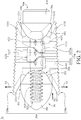
FIG. 2 is a side view of the spinal intervertebral body fusion device inFIG. 1 ; -
FIG. 3 is a perspective view of the spinal intervertebral body fusion device inFIG. 2 ; -
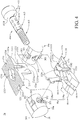
FIG. 4 is an exploded view of the spinal intervertebral body fusion device inFIG. 2 ; -
FIG. 5 is a partial enlarged view of the spinal intervertebral body fusion device inFIG. 2 ; -
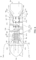
FIG. 6 depicts the spinal intervertebral body fusion device inFIG. 2 before the spinal intervertebral body fusion device is expanded; -
FIG. 7 is a perspective view of the spinal intervertebral body fusion device inFIG. 6 ; -
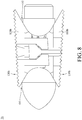
FIG. 8 is a side view of a spinal intervertebral body fusion device according to another embodiment of the disclosure; -
FIG. 9 is a side view of a spinal intervertebral body fusion device according to still another embodiment of the disclosure; -
FIG. 10 is a side view of a spinal intervertebral body fusion device according to still yet another embodiment of the disclosure; -
FIG. 11 depicts a side view of a spinal intervertebral body fusion device according to further another embodiment of the disclosure before the spinal intervertebral body fusion device is expanded; -
FIG. 12 depicts a side view of the spinal intervertebral body fusion device inFIG. 11 when the spinal intervertebral body fusion device is expanded; -
FIG. 13 is a perspective view of a spinal intervertebral body fusion device according to still further another embodiment of the disclosure; and -
FIG. 14 is a front view of the spinal intervertebral body fusion device inFIG. 13 . - In the following detailed description, for purposes of explanation, numerous specific details are set forth in order to provide a thorough understanding of the disclosed embodiments. It will be apparent, however, that one or more embodiments may be practiced without these specific details.
- In addition, for the purpose of simple illustration, well-known features may be drawn schematically, and some unnecessary details may be omitted from the drawings. And the size or ratio of the features in the drawings of the present disclosure may be exaggerated for illustrative purposes, but the present disclosure is not limited thereto. Note that the actual size and designs of the product manufactured based on the teaching of the present disclosure may also be properly modified according to any actual requirement.
- Further, as used herein, the terms "end", "part", "portion" or "area" may be used to describe a technical feature on or between component(s), but the technical feature is not limited by these terms. In addition, unless otherwise specified, the term "substantially", "approximately" or" about" may be used herein to provide an industry-accepted tolerance to its corresponding term without resulting in a change in the basic function of the subject matter at issue.
- Furthermore, unless otherwise defined, all the terms used in the disclosure, including technical and scientific terms, have their ordinary meanings that can be understood by those skilled in the art. Moreover, the definitions of the above terms are to be interpreted as being consistent with the technical fields related to the disclosure. Unless specifically defined, these terms are not to be construed as too idealistic or formal meanings.
- Firstly, please refer to
FIG. 1 , a spinal intervertebral body fusion device 1a is provided. As shown, the spinal intervertebral body fusion device 1a is configured to be implanted into the space originally occupied by anintervertebral disc 92 betweenvertebral bodies 91; that is, the spinal intervertebral body fusion device 1a is able to replace the removedintervertebral disc 92 between thevertebral bodies 91. Particularly, the spinal intervertebral body fusion device 1a is able to be adjusted to an optimal size to restore and maintain the required height of the intervertebral space and required position of the vertebral body. - In this and some other embodiments, the spinal intervertebral body fusion device 1a may be, but not limited to, manufactured by 3D printing technology and its material is biocompatible and has sufficient rigidity to provide proper support to the
vertebral body 91 and maintain the desired position of thevertebral body 91, such as titanium alloy, iron-based alloy, cobalt alloy, polymer material, ceramic or composite material thereof, but the disclosure is not limited thereto. - The spinal intervertebral body fusion device 1a is configured for vertebral body fusion. Note that the spinal intervertebral body fusion device 1a may have rough surfaces to aid the fusion process, but these features are omitted from the drawings for the purpose of simple illustration. Also, the spinal intervertebral body fusion device 1a is adjustable in size and shape, allowing the surgeon to manually adjust it to fit the required disc space so as to provide proper support to the adjacent
vertebral bodies 91 and maintain the desired position of thevertebral bodies 91. In detail, please refer toFIGS. 2-5 ,FIG. 2 is a side view of the spinal intervertebral body fusion device 1a inFIG. 1 ,FIG. 3 is a perspective view of the spinal intervertebral body fusion device 1a inFIG. 2 ,FIG. 4 is an exploded view of the spinal intervertebral body fusion device 1a inFIG. 2 , andFIG. 5 is a partial enlarged view of the spinal intervertebral body fusion device inFIG. 2 . In this and some other embodiments, the spinal intervertebral body fusion device 1a at least includes anadjustable spacer 10a, a first pushingpiece 20a, a second pushingpiece 30a, and anoperative piece 40a. - The
adjustable spacer 10a includes a first supportingbody 110a and a second supportingbody 120a. The first supportingbody 110a and the second supportingbody 120a are movably installed to each other. Specifically, in this embodiment, the first supportingbody 110a includes a first supportingplate portion 111a and at least one firstengagement arm portion 113a, the second supportingbody 120a includes a second supportingplate portion 121a and at least one secondengagement arm portion 123a, wherein the at least one secondengagement arm portion 123a each have a pair ofengaging structures 1231a spaced apart from each other. - As shown, in this embodiment, the first supporting
body 110a includes two firstengagement arm portions 113a respectively stand at two opposite sides of the first supportingplate portion 111a. However, the quantity of the first engagement arm portions of the first supporting body is not limited; in some other embodiments, the first supporting body may have only one first engagement arm portion. In addition, in this embodiment, the second supportingbody 120a includes two secondengagement arm portions 123a respectively stand at two opposite sides of the second supportingplate portion 121a. However, the quantity of the second engagement arm portion of the second supporting body is not limited; in some other embodiments, the second supporting body may have only one second engagement arm portion. - In this and some other embodiments, the first
engagement arm portion 113a of the first supportingbody 110a is movably engaged into the gap between the engagingstructures 1231a of the secondengagement arm portion 123a of the second supportingbody 120a, such that the firstengagement arm portion 113a and the secondengagement arm portion 123a are allowed to slide with each other along their extension directions. As such, the first supportingbody 110a and the second supportingbody 120a are movable toward or away from each other, making theadjustable spacer 10a switchable between an expanded status (as shown inFIGS. 1-2 ) and an unexpanded status (as shown inFIGS. 6-7 mentioned in later paragraphs). - Note that, in this and some other embodiments, the first supporting
body 110a and the second supportingbody 120a of theadjustable spacer 10a may be 3D printed in the same step; that is, the first supportingbody 110a and the second supportingbody 120a were 3D printed together. In such a case, theadjustable spacer 10a is 3D printed in a single process. Therefore, when the first supportingbody 110a and the second supportingbody 120a are formed, they also self-assemble to become theadjustable spacer 10a. - Herein, the usage of the spinal intervertebral body fusion device 1a may be used as a reference to define the spatial terms "front side" and "back side" used below. As shown in
FIG. 1 orFIG. 2 , the front side of the spinal intervertebral body fusion device 1a may indicate the left part of the figure, and the back side of the spinal intervertebral body fusion device 1a may indicate the right part of the figure. These spatial terms also apply to the components of the spinal intervertebral body fusion device 1a, but these terms are merely for the purpose of clear illustration, but disclosure is not limited thereto. - The cooperation of the first pushing
piece 20a, the second pushingpiece 30a, andoperative piece 40a can achieve the status switching of theadjustable spacer 10a between the expanded status and the unexpanded status. In detail, in this and some other embodiments, the first supportingplate portion 111a of the first supportingbody 110a of theadjustable spacer 10a has at least one firstinclined contact surface 1111 respectively located at the front side and the back side of the first supportingplate portion 111a; the second supportingplate portion 121a of the second supportingbody 120a of theadjustable spacer 10a has at least one secondinclined contact surface 1211 respectively located at the front side and the back side of the second supportingplate portion 121a. In such an arrangement, the first supportingplate portion 111a and the second supportingplate portion 121a together form a first opening O1 and a second opening O2 respectively located at the front side and the back side of theadjustable spacer 10a, as shown inFIGS. 2-3 , the first opening O1 and the second opening O2 are respectively located at two opposite sides of theadjustable spacer 10a and are tapered towards each other. Note that the size of the first opening O1 and the second opening O2 changes as theadjustable spacer 10a switches between the expanded status and the unexpanded status. - The first pushing
piece 20a is located at the first opening O1. In this and some other embodiments, the first pushingpiece 20a has afirst push surface 201 configured to contact and push the firstinclined contact surface 1111 of the first supportingplate portion 111a and the secondinclined contact surface 1211 of the second supportingplate portion 121a that are located at the front side. The second pushingpiece 30a is located at the second opening O2. In this and some other embodiments, the second pushingpiece 30a has asecond push surface 301 configured to contact and push the firstinclined contact surface 1111 of the first supportingplate portion 111a and the secondinclined contact surface 1211 of the second supportingplate portion 121a that are located at the back side. Theoperative piece 40a is movably disposed through asecond mounting hole 302 of the second pushingpiece 30a and the space (not numbered) between the first supportingplate portion 111a and the second supportingplate portion 121a, and is screwed to a first mountinghole 202 of the first pushingpiece 20a. When theoperative piece 40a is forced to rotate with respect to theadjustable spacer 10a, theoperative piece 40a is able to force the first pushingpiece 20a and the second pushingpiece 30a to move away from each other so as to switch theadjustable spacer 10a from the expanded status to the unexpanded status. - In more detail, in this and some other embodiments, the
operative piece 40a is an integrally formed single piece and at least includes ahead portion 411, aneck portion 413, and a threadedportion 415. Thehead portion 411 is located at the back side of the spinal intervertebral body fusion device 1a and is configured for the surgeon to manually operate the spinal intervertebral body fusion device 1a. Theneck portion 413 is connected to and located between thehead portion 411 and the threadedportion 415. Part of thehead portion 411 and part of theneck portion 413 are disposed through thesecond mounting hole 302 of the second pushingpiece 30a. The other part of theneck portion 413 is accommodated in the space between the first supportingplate portion 111a and the second supportingplate portion 121a. In this or some other embodiments, theneck portion 413 haspores 4131, and thepores 4131 allow the nearby tissues to grow into the spinal intervertebral body fusion device 1a so as to aid the fusion process. Note that the size and shape of thepores 4131 and the distance among thepores 4131 are not limited and may be modified according to actual requirements. In some embodiments, thehead portion 411 of theoperative piece 40a may also have thepores 4131 to further aid the fusion process. - The threaded
portion 415 has an external thread (not numbered) and is configured to be screwed into the first mountinghole 202 of the first pushingpiece 20a. As shown, there is an internal thread (not numbered) in the first mountinghole 202 for the engagement with the threadedportion 415 of theoperative piece 40a. - In addition, as shown in
FIG. 5 , in this and some other embodiments, thehead portion 411 of theoperative piece 40a has anengaging surface 4111 facing towards theadjustable spacer 10a, the second pushingpiece 30a has anannular protrusion 304 located in thesecond mounting hole 302 and radially extending towards the center (not numbered) of thesecond mounting hole 302, theannular protrusion 304 has an innerengaging surface 3031 and an outerengaging surface 3032 respectively located at a side of theannular protrusion 304 closer to the first pushingpiece 20a and a side of theannular protrusion 304 away from the first pushingpiece 20a. Thesecond mounting hole 302 is substantially an hourglass-shaped hole. It is understood that both of the innerengaging surface 3031 and the outer engagingsurface 3032 are inclined surfaces. The innerengaging surface 3031 of theannular protrusion 304 of the second pushingpiece 30a is configured to contact and push theneck portion 413 of theoperative piece 40a, and theengaging surface 4111 of thehead portion 411 of theoperative piece 40a is configured to contact and push the outer engagingsurface 3032 of theannular protrusion 304 of the second pushingpiece 30a. In such an arrangement, at least part of theannular protrusion 304 is located in anannular slot 412 formed by the engagingsurface 4111 of thehead portion 411 and theneck portion 413. Theannular slot 412 is an endless annular slot, thus theannular slot 412 allows the second pushingpiece 30a to rotate with respect to theoperative piece 40a but does not allow the second pushingpiece 30a to move in an extension direction of theoperative piece 40a. That is, the second pushingpiece 30a is rotatably sleeved on theoperative piece 40a but is unable to move along theoperative piece 40a. Therefore, theoperative piece 40a can move the second pushingpiece 30a forward and backward together. - In this and some other embodiments, the second pushing
piece 30a and theoperative piece 40a may be 3D printed in the same step; that is, the second pushingpiece 30a and theoperative piece 40a were 3D printed together at the same time. As such, when the second pushingpiece 30a and theoperative piece 40a are formed, they also self-assemble to form the arrangement shown inFIG. 5 . - Herein, please refer to
FIG. 2 andFIGS. 4-5 , when theoperative piece 40a is rotated in a way to gradually screw the threadedportion 415 into the first mountinghole 202 of the first pushingpiece 20a, theoperative piece 40a is rotated with respect to the second pushingpiece 30a and the first pushingpiece 20a, but the second pushingpiece 30a presses against the firstinclined contact surface 1111 of the first supportingplate portion 111a and the secondinclined contact surface 1211 of the second supportingplate portion 121a and is unable to move along theoperative piece 40a, thus this movement of theoperative piece 40a will pull the first pushingpiece 20a towards the second pushingpiece 30a, as the arrow A1 shown in FIG. - By doing so, the
first push surface 201 of the first pushingpiece 20a and thesecond push surface 301 of the second pushingpiece 30a can clamp and push the firstinclined contact surfaces 1111 of the first supportingplate portion 111a of the first supportingbody 110a and the secondinclined contact surfaces 1211 of the second supportingplate portion 121a of the second supportingbody 120a, since thefirst push surface 201 and thesecond push surface 301 and the firstinclined contact surface 1111 and the secondinclined contact surface 1211 are all inclined surfaces, thus the first pushingpiece 20a and the second pushingpiece 30a which gradually move toward each other can force the first supportingplate portion 111a of the first supportingbody 110a and the second supportingplate portion 121a of the second supportingbody 120a to move away from each other, as the arrows A2 and A3 shown inFIG. 2 . During this movement, the firstengagement arm portion 113a of the first supportingbody 110a and the secondengagement arm portion 123a of the second supportingbody 120a are moved along each other so as to ensure the predetermined paths of the first supportingplate portion 111a and the second supportingplate portion 121a. - It is understood that the distance between the first supporting
plate portion 111a of the first supportingbody 110a and the second supportingplate portion 121a of the second supportingbody 120a can be adjusted by rotating theoperative piece 40a to change the relative position of the first pushingpiece 20a and the second pushingpiece 30a. In this or some other embodiments, the end portion of the firstengagement arm portion 113a has at least one first stoppingsurface 1131, and the end portion of the engagingstructure 1231a of the secondengagement arm portion 123a has a second stoppingsurface 12311, where the first stoppingsurface 1131 substantially faces away from the second supportingplate portion 121a of the second supportingbody 120a, and the second stoppingsurface 12311 substantially faces away from the first supportingplate portion 111a of the first supportingbody 110a. Therefore, when the distance of the first supportingplate portion 111a of the first supportingbody 110a and the second supportingplate portion 121a of the second supportingbody 120a is increased to a specific value, the first stoppingsurfaces 1131 of the firstengagement arm portions 113a press against the second stoppingsurfaces 12311 of the engagingstructures 1231a of the secondengagement arm portions 123a, which prevents the first supportingplate portion 111a of the first supportingbody 110a and the second supportingplate portion 121a of the second supportingbody 120a from moving further away from each other, that is, the first stoppingsurfaces 1131 and the second stoppingsurfaces 12311 limits the maximum adjustment range of theadjustable spacer 10a. - Accordingly, the surgeon is allowed to simply rotate the
operative piece 40a to adjust the size of the spinal intervertebral body fusion device 1a to fit the required disc space. This not only facilitates the implantation operation but also provides proper support to the vertebral body and maintains the desired position of the vertebral body. Also, the cooperation of theoperative piece 40a and the first pushingpiece 20a achieves a stepless adjustment of the size of the spinal intervertebral body fusion device 1a, enabling a precise adjustment of the size of the spinal intervertebral body fusion device 1a to provide optimal support to the adjacent vertebral bodies. - Note that the inclinations of the
first push surface 201 of the first pushingpiece 20a, thesecond push surface 301 of the second pushingpiece 30e, and the firstinclined contact surface 1111 and the secondinclined contact surface 1211 of theadjustable spacer 10a are not limited and may be modified according to the actual requirements. - In addition, in this and some other embodiments, the first pushing
piece 20a has at least onefirst protrusion 203, and the second pushingpiece 30e has at least onesecond protrusion 304. The first supportingplate portion 111a of the first supportingbody 110a further has at least onerecess 1114 respectively formed on the firstinclined contact surfaces 1111, the second supportingplate portion 121a of the second supportingbody 120a further has at least onerecess 1214 respectively formed on the second inclined contact surfaces 1211. Thefirst protrusions 203 are respectively located on two opposite sides of thefirst push surface 201 of the first pushingpiece 20a relative close to the first supportingplate portion 111a and the second supportingplate portion 121a and respectively located in therecess 1114 and therecess 1214 at the front side. In this arrangement, the first pushingpiece 20a is not allowed to move in a direction perpendicular to the extension direction of theoperative piece 40a. Thesecond protrusions 303 are respectively located on two opposite sides of thesecond push surface 301 of the second pushingpiece 30a relative close to the first supportingplate portion 111a and the second supportingplate portion 121a and respectively located in therecess 1114 and therecess 1214 at the back side. In this arrangement, the second pushingpiece 30a is either not allowed to move in a direction perpendicular to the extension direction of theoperative piece 40a. - In addition, in this and some other embodiments, the first supporting
plate portion 111a of the first supportingbody 110a has a plurality offirst protrusion 1110 formed on a side of the first supportingplate portion 111a facing away from the second supportingplate portion 121a, and the second supportingplate portion 121a of the second supportingbody 120a has a plurality ofsecond protrusions 1210 formed on the side of the second supportingplate portion 121a facing away from the first supportingplate portion 111a. Thefirst protrusions 1110 and thesecond protrusions 1210 can increase the contact area of the spinal intervertebral body fusion device 1a and the adjacentvertebral bodies 91 to improve the fusion process. Note that the shape and size of thefirst protrusions 1110 and thesecond protrusions 1210 are not limited. - Further, in this or some other embodiments, the first supporting
plate portion 111a of the first supportingbody 110a of theadjustable spacer 10a may have at least onefirst passage 1113, and the second supportingplate portion 121a of the second supportingbody 120a of theadjustable spacer 10a may have at least onesecond passage 1213. Thefirst passage 1113 and thesecond passage 1213 are connected to the space between the first supportingplate portion 111a and the second supportingplate portion 121a, which allows the nearby tissues to grow into the space and reach the features in the space, such as theneck portion 413 and the threadedportion 415 of theoperative piece 40a, but the disclosure is not limited thereto. - Moreover, in some embodiments, the first supporting
body 110a and the second supportingbody 120a of theadjustable spacer 10a may also have pores (not shown) to allow the nearby tissues to grow into the spinal intervertebral body fusion device 1a to further aid the fusion process. In some other embodiments, the spinal intervertebral body fusion device may have a porosity of approximately 20%-60%, but the disclosure is not limited thereto. - In addition, in this and some other embodiments, the spinal intervertebral body fusion device 1a has a
leading end 50 to facilitate the insertion of the spinal intervertebral body fusion device 1a into the space between thevertebral bodies 91. The leadingend 50 is located at the side of the first pushingpiece 20a facing away from the second pushingpiece 30a. The leadingend 50 and the first pushingpiece 20a may be an integrally formed single piece. The leadingend 50 may have a leadingstructure 501 protruding in a direction away from the second pushingpiece 30a and in a shape suitable for invading the space between thevertebral bodies 91, facilitating the placement of the spinal intervertebral body fusion device 1a. - In addition, to aid the fusion process of the spinal intervertebral body fusion device 1a and the adjacent
vertebral bodies 91, the first supportingbody 110a and the second supportingbody 120a of theadjustable spacer 10a may be in shape and size substantially matching the contour of thevertebral bodies 91, but the disclosure is not limited thereto. Note that the size and shape of the first supporting body, the second supporting body and the other components of the spinal intervertebral body fusion device are not particularly limited. In short, the overall size and shape, such as length, width, height or proportion, of the spinal intervertebral body fusion device are not particularly limited and may be modified according to actual requirements. - Please refer to
FIG. 2 or4 and further refer toFIGS. 6-7 to introduce the unexpanded status of the spinal intervertebral body fusion device 1a, whereFIG. 6 depicts the spinal intervertebral body fusion device 1a inFIG. 2 before the spinal intervertebral body fusion device is expanded, andFIG. 7 is a perspective view of the spinal intervertebral body fusion device 1a inFIG. 6 . As shown, as the spinal intervertebral body fusion device 1a is in the unexpanded status, the first supportingplate portion 111a of the first supportingbody 110a and the second supportingplate portion 121a of the second supportingbody 120a are in a position to be able to engage with each other, such that the spinal intervertebral body fusion device 1a is able to stay in the current status by itself. - In detail, in this or some other embodiments, the first supporting
plate portion 111a of the first supportingbody 110a of theadjustable spacer 10a further has at least one first inclined stoppingsurface 1112 respectively located at two opposite sides of the firstengagement arm portion 113a and respectively corresponding to the engagingstructures 1231a of the secondengagement arm portion 123a of the second supportingbody 120a. From the viewpoint ofFIG. 2 , the end of the secondengagement arm portion 123a is located between the second supportingplate portion 121a and the first inclined stoppingsurfaces 1112, thus the first inclined stoppingsurfaces 1112 are at the end of the travel path of the secondengagement arm portion 123a. The second supportingplate portion 121a of the second supportingbody 120a of theadjustable spacer 10a further has at least one second inclined stoppingsurface 1212 located between the engagingstructures 1231a and corresponding to the firstengagement arm portion 113a. From the viewpoint ofFIG. 2 , the end of the firstengagement arm portion 113a is located between the first supportingplate portion 111a and the second inclined stoppingsurface 1212, thus the second inclined stoppingsurface 1212 is located at the end of the travel path of the firstengagement arm portion 113a. - In such an arrangement, when the threaded
portion 415 of theoperative piece 40a is gradually removed out of the first mountinghole 202 of the first pushingpiece 20a to make the first pushingpiece 20a and the second pushingpiece 30a move away from each other, the first supportingplate portion 111a and the second supportingplate portion 121a of theadjustable spacer 10a are allowed to move towards each other, such that theadjustable spacer 10a can be switched to the unexpanded status. In the unexpanded status, the firstengagement arm portions 113a of the first supportingbody 110a press against the second inclined stoppingsurfaces 1212 of the second supportingplate portion 121a of the second supportingbody 120a, and the engagingstructures 1231a of the secondengagement arm portions 123a of the second supportingbody 120a presses against the first inclined stoppingsurfaces 1112 of the first supportingplate portion 111a of the first supportingbody 110a. The friction between the firstengagement arm portions 113a and the second inclined stoppingsurfaces 1212 and the engagingstructures 1231a and the first inclined stoppingsurfaces 1112 may cause the first supportingbody 110a and the second supportingbody 120a of theadjustable spacer 10a to temporarily fix to each other. This makes the spinal intervertebral body fusion device 1a stay in the current status itself. Also, the first inclined stoppingsurfaces 1112 can stop the secondengagement arm portion 123a from sticking out of the outer surface of the first supportingplate portion 111a, and the second inclined stoppingsurfaces 1212 can stop the firstengagement arm portions 113a from sticking out of the outer surface of the second supportingplate portion 121a. - Accordingly, before the usage of the spinal intervertebral body fusion device 1a, the spinal intervertebral body fusion device 1a is able to stay in the unexpanded status by itself. In the unexpanded status, the spinal intervertebral body fusion device 1a is in its possible smallest volume, and its components are all fixed to one another. Therefore, the spinal intervertebral body fusion device 1a in the unexpanded status is much compact in size so that it is good for storage and carry. In some applications, the first inclined stopping
surfaces 1112 and the second inclined stoppingsurfaces 1212 may be approximately at 80-95 degrees respectively to the first supportingplate portion 111a and the second supportingplate portion 121a, but the inclinations of the first inclined stoppingsurfaces 1112 and the second inclined stoppingsurfaces 1212 are not limited and may be modified according to actual requirements. - As such, the spinal intervertebral body fusion device 1a has a certain amount of change in its shape for achieving the purpose of fitting the required disc space between the vertebral bodies. Note that, according to the requirement of the space between the vertebral bodies, the lengths of the first engagement arm portion, the second engagement arm portion, and/or the operative piece may be modified to obtain a proper adjustment range of the spinal intervertebral body fusion device. In some embodiments of the disclosure, the height of the spinal intervertebral body fusion device, from the unexpanded status to the expanded status, may increase from approximately 5 millimeters to 8 millimeters; that is, the spinal intervertebral body fusion device at least has approximately 3 millimeters of change in height. In another embodiment, the height of the spinal intervertebral body fusion device, from the unexpanded status to the expanded status, may increase from approximately 9 millimeters to 12 millimeters or from approximately 13 millimeters to 16 millimeters. Herein, the height indicates the furthest distance between the first supporting plate portion of the first supporting body and the second supporting plate portion of the second supporting body which are located on the same side (e.g., the front side or back side), meaning the farthest distance that the spinal intervertebral body fusion device can separate the adjacent vertebral bodies.
- Further, the spinal intervertebral body fusion device 1a can also be used to correct the spinal-related symptoms, such as lordosis. In detail, as shown in
FIG. 2 , in this embodiment, the thicknesses of the first supportingplate portion 111a of the first supportingbody 110a and the second supportingplate portion 121a of the second supportingbody 120a decrease from the first opening O1 toward the second opening O2, such that the spinal intervertebral body fusion device 1a is tapered from the front side towards the back side. In such a configuration, the spinal intervertebral body fusion device 1a is able to push thevertebral bodies 91 to the desired positions to improve the lordosis. - The spinal intervertebral body fusion device is not restricted to be shaped for the lordosis. For example, please refer to
FIG. 8 , a spinal intervertebral body fusion device 1b is provided for correcting kyphosis. One of the main differences between this and the previous embodiments is the thickness of the first and second supporting bodies, thus the same and similar parts will not be repeated hereinafter. In this embodiment, the thicknesses of a first supportingplate portion 111b of a first supportingbody 110b and a second supportingplate portion 121b of a second supportingbody 120b increase from the first opening O1 towards the second opening O2, such that the spinal intervertebral body fusion device 1b is tapered from the back side towards the front side. In such a configuration, the spinal intervertebral body fusion device 1b is able to push thevertebral bodies 91 to the desired positions to improve the kyphosis. - As discussed above, since the first supporting plate portion and the second supporting plate portion have thickness variations from the first opening to the second opening, the first engagement arm portion and the second engagement arm portion are required to linearly move with respect to each other to correct the lordosis or kyphosis, but the disclosure is not limited thereto. Please refer to
FIG. 9, FIG. 9 is a side view of a spinal intervertebral body fusion device 1c according to still another embodiment of the disclosure. For the purpose of simple description, only the differences between this and the previous embodiments will be illustrated below, and the same and similar parts can be obtained with the reference of the aforementioned discussions. - As shown in
FIG. 9 , from the first opening O1 to the second opening O2 of the spinal intervertebral body fusion device 1c, the thicknesses of a first supporting plate portion 111c and a second supportingplate portion 121c do not change. In such a configuration, firstengagement arm portions 113c of a first supportingbody 110c may extend in a curved manner, and engagingstructures 1231c of secondengagement arm portions 123c of a second supportingbody 120c may extend in a curved manner corresponding to the shape of the firstengagement arm portions 113c. The cooperation of the firstengagement arm portions 113c and the secondengagement arm portions 123c enables the inclination adjustment of the second supportingplate portion 121c with respect to the first supporting plate portion 111c, as the arrow A4 shown inFIG. 9 . Therefore, during the movement of the spinal intervertebral body fusion device 1c from the unexpanded status to the expanded status, the change of the first opening O1 is greater than that of the second opening O2, and the spinal intervertebral body fusion device 1c forms a shape tapered from the front side to the back side. Similar to the aforementioned spinal intervertebral body fusion device 1a, the spinal intervertebral body fusion device 1c is also able to push thevertebral bodies 91 to the desired positions to improve the lordosis. In one embodiment, the second supportingplate portion 121c may be moved to be at approximately 10 degrees to the first supporting plate portion 111c. - Alternatively, please refer to
FIG. 10, FIG. 10 is a side view of a spinal intervertebral body fusion device 1d according to still yet another embodiment of the disclosure. For the purpose of simple description, only the differences between this and the previous embodiments will be illustrated below, and the same and similar parts can be obtained with the reference of the aforementioned discussions. As shown inFIG. 10 , in the spinal intervertebral body fusion device 1d, firstengagement arm portions 113d of a first supportingbody 110d extend in a curved manner which is opposite to that of the firstengagement arm portion 113c inFIG. 9 , and engagingstructures 1231d of secondengagement arm portions 123d of a second supportingbody 120d extend in a curved manner which is corresponding to the shape of the firstengagement arm portions 113d but is opposite to that of the secondengagement arm portion 123c inFIG. 9 . The cooperation of the firstengagement arm portions 113d and the secondengagement arm portions 123d also enables the inclination adjustment of the second supportingplate portion 121d with respect to the first supporting plate portion 111d, as the arrow A5 shown inFIG. 10 . During the movement of the spinal intervertebral body fusion device 1d from the unexpanded status to the expanded status, the change of the first opening O1 is smaller than that of the second opening O2, and the spinal intervertebral body fusion device 1d forms a shape tapered from the back side to the front side. Similar to the aforementioned spinal intervertebral body fusion device 1b, the spinal intervertebral body fusion device 1d is also able to push thevertebral bodies 91 to the desired positions to improve the kyphosis. In one embodiment, the second supportingplate portion 121d may be moved to be at approximately 10 degrees to the first supporting plate portion 111d. - In addition, the first pushing piece and the second pushing piece may not move toward or away from each other during the movement of the operative piece. Please refer to
FIGS. 11-12 ,FIG. 11 depicts a side view of a spinal intervertebral body fusion device 1e according to further another embodiment of the disclosure before the spinal intervertebral body fusion device is expanded, andFIG. 12 depicts a side view of the spinal intervertebral body fusion device 1e inFIG. 11 when the spinal intervertebral body fusion device is expanded. For the purpose of simple description, only the differences between this and the previous embodiments will be illustrated below, and the same and similar parts can be obtained with the reference of the aforementioned discussions. - As shown, a first pushing
piece 20e and aleading end 50e may be two independent objects, and the second pushingpiece 30e, in this embodiment, is allowed to be moved along anoperative piece 40e. In detail, the first pushingpiece 20e is sleeved on and engaged with a threadedportion 415e of theoperative piece 40e, and one end of the threadedportion 415e is fixed to theleading end 50e. As such, the first pushingpiece 20e is movable along the threadedportion 415e of theoperative piece 40e and able to move toward or away from theleading end 50e. Aneck portion 413e of theoperative piece 40e also has threads (not numbered). The second pushingpiece 30e is sleeved on and engaged with the threads of theneck portion 413e. As such, the second pushingpiece 30e is movable along theneck portion 413e and able to move toward or away from the first pushingpiece 20e. When theoperative piece 40e is forced to rotate, the first pushingpiece 20e and the second pushingpiece 30e clamp the front side and back side of the first supportingbody 110e and the second supportingbody 120e, such that theoperative piece 40e is able to gradually pull the first pushingpiece 20e towards the second pushingpiece 30e and pull the second pushingpiece 30e towards the first pushingpiece 20e, achieving the adjustment of the distance between the first supportingbody 110e and the second supportingbody 120e. Since the operation of theoperative piece 40e can simultaneously force the first pushingpiece 20e and the second pushingpiece 30e to move toward or away from each other, the distance between the end of theoperative piece 40e and the tip of theleading end 50e does not change during status switching of the spinal intervertebral body fusion device 1e. - Note that the adjustable spacer is not restricted to have two movable pieces. For example, please refer to
FIGS. 13-14 ,FIG. 13 is a perspective view of a spinal intervertebral body fusion device 1f according to still further another embodiment of the disclosure, andFIG. 14 is a front view of the spinal intervertebral body fusion device 1f inFIG. 13 . For the purpose of simple description, only the differences between this and the previous embodiments will be illustrated below, and the same and similar parts can be obtained with the reference of the aforementioned discussions. - As shown in
FIG. 13 , anadjustable spacer 10f of the spinal intervertebral body fusion device 1f includes a first supportingbody 110f, a second supportingbody 120f, a third supportingbody 130f, and a fourth supportingbody 140f which are respectively located at the four different sides thereof. That is, the first supportingbody 110f, the second supportingbody 120f, the third supportingbody 130f, and the fourth supportingbody 140f are respectively located at four different sides of an operative piece 40f of the spinal intervertebral body fusion device 1f. The movement of the operative piece 40f can force a first supportingplate portion 111f of the first supportingbody 110f, a second supportingplate portion 121f of the second supportingbody 120f, a third supportingplate portion 131f of the third supportingbody 130f, and a fourth supportingplate portion 141f of the fourth supportingbody 140f to move away from one another, such that the spinal intervertebral body fusion device 1f is adjustable in four different directions. - Specifically, the first supporting
body 110f, the second supportingbody 120f, the third supportingbody 130f, and the fourth supportingbody 140f are similar to the first supporting body and the second supporting body of the previous embodiments, and their features for installation may be misaligned to avoid structural interference, thus the same and similar parts will not be repeated hereinafter. In addition, based on the configuration of theadjustable spacer 10f, the first push surface 201f of the first pushingpiece 20f and the second push surface 301f of the second pushing piece 30f may each include four surfaces or be a single conical surface corresponding to the inclined contact surfaces of the first supportingplate portion 111f, the second supportingplate portion 121f, the third supportingplate portion 131f, and the fourth supportingplate portion 141f. As such, the first pushingpiece 20f and the second pushing piece 30f are able to simultaneously push the first supportingplate portion 111f, the second supportingplate portion 121f, the third supportingplate portion 131f, and the fourth supportingplate portion 141f while being forced by theoperative piece 10f - As the arrows shown in
FIG. 14 , when theadjustable spacer 10f is moved, the first supportingplate portion 111f, the second supportingplate portion 121f, the third supportingplate portion 131f, and the fourth supportingplate portion 141f are respectively moved toward four different directions. In some applications, during the process that the spinal intervertebral body fusion device 1f is switched from the unexpanded status to the expanded status, the distance between two opposite surfaces of the third supportingplate portion 131f and the fourth supportingplate portion 141f may increase from approximately 9.5 millimeters to 15 millimeters, and the distance between two opposite surfaces of the first supportingplate portion 111f and the second supportingplate portion 121f may increase from approximately 5 millimeters to 16 millimeters, but the disclosure is not limited thereto. - It is understood that the concept of the spinal intervertebral body fusion device 1a and the spinal intervertebral body fusion device 1b may apply to the spinal intervertebral body fusion device 1f. For example, in some embodiments, the first supporting body, the second supporting body, the third supporting body, and the fourth supporting body may have the thickness variation as the first supporting body and the second supporting body of the spinal intervertebral body fusion device 1a and/or the spinal intervertebral body fusion device 1b according to actual requirements.
- According to the spinal intervertebral body fusion device as discussed in the above embodiments of the disclosure, the first supporting plate portion and the second supporting plate portion are movably installed to each other and together clamp the first pushing piece and the second pushing piece respectively at the first opening and the second opening on opposite sides, thus the operative piece that is located between the first supporting plate portion and the second supporting plate portion and connected to the first pushing piece and the second pushing piece is able to force the first pushing piece and the second pushing piece to clamp the first supporting plate portion and the second supporting plate portion so as to force the first supporting plate portion and the second supporting plate portion to move away from each other, achieving the size adjustment of the spinal intervertebral body fusion device. As such, the spinal intervertebral body fusion device is able to be adjusted to an optimal size to restore and maintain the height of the intervertebral space and position of the vertebral body.
- It will be apparent to those skilled in the art that various modifications and variations can be made to the present disclosure. It is intended that the specification and examples be considered as exemplary embodiments only, with a scope of the disclosure being indicated by the following claims and their equivalents.
Claims (14)
- A spinal intervertebral body fusion device (1a, 1b, 1c, 1d, 1f), comprising:an adjustable spacer (10a, 10f), comprising a first supporting plate portion (111a, 111b, 111c, 111f) and a second supporting plate portion (121a, 121b, 121c, 121f), wherein the first supporting plate portion is movably installed on the second supporting plate portion, the first supporting plate portion and the second supporting plate portion together form a first opening (O1) and a second opening (O2) which are respectively located at two opposite sides of the adjustable spacer;a first pushing piece (20a, 20e, 20f), located at the first opening and partially located between and clamped by the first supporting plate portion and the second supporting plate portion;a second pushing piece (30a, 30e, 30f), located at the second opening and partially located between and clamped by the first supporting plate portion and the second supporting plate portion; andan operative piece (40a, 40e, 40f), located between the first supporting plate portion and the second supporting plate portion, and the operative piece movably disposed through the second pushing piece and screwed to the first pushing piece, wherein when the operative piece is activated, the operative piece forces the second pushing piece and the first pushing piece to move towards or away from each other to change a relative position of the first supporting plate portion and the second supporting plate portion;wherein the operative piece has an annular slot (412), and the second pushing piece is partially located in the annular slot.
- The spinal intervertebral body fusion device according to claim 1, wherein the operative piece is an integrally formed single piece, the second pushing piece is an integrally formed single piece, and the second pushing piece is rotatably sleeved on the operative piece and is unable to move in an extension direction of the operative piece.
- The spinal intervertebral body fusion device according to claim 1, wherein the first opening and the second opening are tapered toward each other.
- The spinal intervertebral body fusion device according to claim 1, wherein the adjustable spacer further comprises at least one first engagement arm portion (113a, 113b, 113c, 113d) and at least one second engagement arm portion (123a, 123c, 123d), the at least one first engagement arm portion is integrally formed on the first supporting plate portion and extends toward the second supporting plate portion, the at least one second engagement arm portion is integrally formed on the second supporting plate portion and extends toward the first supporting plate portion, the at least one first engagement arm portion is partially embedded in the at least one second engagement arm portion and is movable along the at least one second engagement arm portion.
- The spinal intervertebral body fusion device according to claim 4, wherein the at least one first engagement arm portion and the at least one second engagement arm portion both extend in a curved manner.
- The spinal intervertebral body fusion device according to claim 4, wherein the first supporting plate portion has at least one first inclined stopping surface (1112) corresponding to the at least one second engagement arm portion (1212), an end of the at least one second engagement arm portion is located between the second supporting plate portion and the at least one first inclined stopping surface, the second supporting plate portion has at least one second inclined stopping surface corresponding to the at least one first engagement arm portion, an end of the at least one first engagement arm portion is located between the first supporting plate portion and the at least one second inclined stopping surface.
- The spinal intervertebral body fusion device according to claim 1, wherein the first pushing piece has at least one first protrusion (203), at least one of the first supporting plate portion and the second supporting plate portion has at least one recess (1114, 1214), and the at least one first protrusion is located in the at least one recess.
- The spinal intervertebral body fusion device according to claim 1, wherein the second pushing piece has at least one second protrusion (303), at least one of the first supporting plate portion and the second supporting plate portion has at least one recess (1114, 1214), and the at least one second protrusion is located in the at least one recess.
- The spinal intervertebral body fusion device according to claim 1, wherein the operative piece is an integrally formed single piece, the operative piece comprises a head portion (411), a neck portion (413, 413e), and a threaded portion (415,415e), the head portion is located at the second opening and partially clamped by the first supporting plate portion and the second supporting plate portion, the neck portion is located between the first supporting plate portion and the second supporting plate portion and connected between the head portion and the threaded portion, the head portion and the neck portion form the annular slot, at least part of the head portion and at least part of the neck portion are disposed through the second pushing piece, the neck portion has pores (4131), and the threaded portion is screwed to the first pushing piece.
- The spinal intervertebral body fusion device according to claim 1, wherein thicknesses of the first supporting plate portion and the second supporting plate portion decrease from the first opening towards the second opening.
- The spinal intervertebral body fusion device according to claim 1, wherein thicknesses of the first supporting plate portion and the second supporting plate portion increase from the first opening towards the second opening.
- The spinal intervertebral body fusion device according to claim 1, wherein the adjustable spacer further comprises a third supporting plate portion (131f) and a fourth supporting plate portion (141f), the third supporting plate portion is movably installed on the fourth supporting plate portion, the first supporting plate portion, the second supporting plate portion, the third supporting plate portion, and the fourth supporting plate portion together form the first opening and the second opening and respectively located at different sides of the operative piece, the first pushing piece is partially located between and clamped by the first supporting plate portion, the second supporting plate portion, the third supporting plate portion, and the fourth supporting plate portion, the second pushing piece is partially located between and clamped by the first supporting plate portion, the second supporting plate portion, the third supporting plate portion, and the fourth supporting plate portion.
- The spinal intervertebral body fusion device according to claim 1, wherein the operative piece and the second pushing piece were 3D printed together.
- The spinal intervertebral body fusion device according to claim 1, wherein the first supporting plate portion and the second supporting plate portion were 3D printed together.
Applications Claiming Priority (1)
| Application Number | Priority Date | Filing Date | Title |
|---|---|---|---|
| TW108140606A TWI736010B (en) | 2019-11-08 | 2019-11-08 | Spinal intervertebral body fusion device |
Publications (2)
| Publication Number | Publication Date |
|---|---|
| EP3818965A1 true EP3818965A1 (en) | 2021-05-12 |
| EP3818965B1 EP3818965B1 (en) | 2024-01-31 |
Family
ID=69055670
Family Applications (1)
| Application Number | Title | Priority Date | Filing Date |
|---|---|---|---|
| EP19219449.6A Active EP3818965B1 (en) | 2019-11-08 | 2019-12-23 | Spinal intervertebral body fusion device |
Country Status (4)
| Country | Link |
|---|---|
| US (1) | US11819420B2 (en) |
| EP (1) | EP3818965B1 (en) |
| CN (1) | CN112773576B (en) |
| TW (1) | TWI736010B (en) |
Cited By (4)
| Publication number | Priority date | Publication date | Assignee | Title |
|---|---|---|---|---|
| EP4119103A1 (en) * | 2021-07-16 | 2023-01-18 | Blue Ocean Spine GmbH | Adjustable intervertebral cage, associated instrument and manufacturing process therefor |
| US12318307B2 (en) | 2021-07-16 | 2025-06-03 | Blue Ocean Spine Gmbh | Adjustable spinal implants, associated instruments and methods |
| US12453640B2 (en) | 2021-07-16 | 2025-10-28 | Blue Ocean Spine Gmbh | Adjustable spinal implants, associated instruments and methods |
| US12533242B2 (en) | 2023-01-18 | 2026-01-27 | Blue Ocean Spine Gmbh | Adjustable spinal implants and related deployment instruments |
Families Citing this family (33)
| Publication number | Priority date | Publication date | Assignee | Title |
|---|---|---|---|---|
| US10426632B2 (en) | 2013-03-13 | 2019-10-01 | Life Spine, Inc. | Expandable spinal interbody assembly |
| US12193948B2 (en) | 2013-03-13 | 2025-01-14 | Life Spine, Inc. | Expandable implant assembly |
| US11896494B2 (en) | 2017-07-10 | 2024-02-13 | Life Spine, Inc. | Expandable implant assembly |
| US11806250B2 (en) | 2018-02-22 | 2023-11-07 | Warsaw Orthopedic, Inc. | Expandable spinal implant system and method of using same |
| WO2020251943A1 (en) | 2019-06-10 | 2020-12-17 | Life Spine, Inc. | Expandable implant assembly with compression features |
| US12042395B2 (en) | 2019-06-11 | 2024-07-23 | Life Spine, Inc. | Expandable implant assembly |
| KR102106024B1 (en) * | 2019-10-11 | 2020-04-29 | 주식회사 엔닥 | Variable type cage for vertebra |
| US11857432B2 (en) | 2020-04-13 | 2024-01-02 | Life Spine, Inc. | Expandable implant assembly |
| US11602439B2 (en) * | 2020-04-16 | 2023-03-14 | Life Spine, Inc. | Expandable implant assembly |
| US12336917B2 (en) | 2020-05-15 | 2025-06-24 | Life Spine, Inc. | Steerable implant assembly |
| US11602440B2 (en) | 2020-06-25 | 2023-03-14 | Life Spine, Inc. | Expandable implant assembly |
| US11554020B2 (en) * | 2020-09-08 | 2023-01-17 | Life Spine, Inc. | Expandable implant with pivoting control assembly |
| US11395743B1 (en) | 2021-05-04 | 2022-07-26 | Warsaw Orthopedic, Inc. | Externally driven expandable interbody and related methods |
| US11833059B2 (en) | 2020-11-05 | 2023-12-05 | Warsaw Orthopedic, Inc. | Expandable inter-body device, expandable plate system, and associated methods |
| US11376134B1 (en) | 2020-11-05 | 2022-07-05 | Warsaw Orthopedic, Inc. | Dual expanding spinal implant, system, and method of use |
| US12318308B2 (en) | 2020-11-05 | 2025-06-03 | Warsaw Orthopedic, Inc. | Dual expandable inter-body device |
| US11638653B2 (en) | 2020-11-05 | 2023-05-02 | Warsaw Orthopedic, Inc. | Surgery instruments with a movable handle |
| US11963881B2 (en) | 2020-11-05 | 2024-04-23 | Warsaw Orthopedic, Inc. | Expandable inter-body device, system, and method |
| US12239544B2 (en) | 2020-11-05 | 2025-03-04 | Warsaw Orthopedic, Inc. | Rhomboid shaped implants |
| US12121453B2 (en) | 2020-11-05 | 2024-10-22 | Warsaw Orthopedic, Inc. | Dual wedge expandable implant with eyelets, system, and method of use |
| US11517443B2 (en) | 2020-11-05 | 2022-12-06 | Warsaw Orthopedic, Inc. | Dual wedge expandable implant, system and method of use |
| US11564724B2 (en) | 2020-11-05 | 2023-01-31 | Warsaw Orthopedic, Inc. | Expandable inter-body device, system and method |
| US12171439B2 (en) | 2020-11-05 | 2024-12-24 | Warsaw Orthopedic, Inc. | Protected drill |
| WO2022271280A1 (en) | 2021-06-24 | 2022-12-29 | Warsaw Orthopedic, Inc. | Expandable interbody implant and corresponding surgical tool |
| US12440349B2 (en) | 2021-11-01 | 2025-10-14 | Warsaw Orthopedic, Inc. | Expandable interbody implant and breakoff screw |
| US12295865B2 (en) | 2021-06-24 | 2025-05-13 | Warsaw Orthopedic, Inc. | Expandable interbody implant and corresponding inserter |
| US12485019B2 (en) | 2021-06-24 | 2025-12-02 | Warsaw Orthopedic, Inc. | Parallel jaw inserter |
| US11612499B2 (en) | 2021-06-24 | 2023-03-28 | Warsaw Orthopedic, Inc. | Expandable interbody implant |
| US12533241B2 (en) | 2023-05-16 | 2026-01-27 | Warsaw Orthopedic, Inc. | Distracting and angling expandable interbody device |
| TWI872838B (en) * | 2023-12-01 | 2025-02-11 | 財團法人工業技術研究院 | Expandable spinal implant |
| CN117860444B (en) * | 2024-02-04 | 2024-07-05 | 山东迈尔医疗科技有限公司 | Porous centrum fusion device |
| CN118845316B (en) * | 2024-09-23 | 2024-12-27 | 北京理贝尔生物工程研究所有限公司 | Intervertebral support tools |
| CN120000387B (en) * | 2025-04-09 | 2025-11-25 | 武汉医佳宝生物材料有限公司 | An interbody fusion device and vertebral fixation system |
Citations (2)
| Publication number | Priority date | Publication date | Assignee | Title |
|---|---|---|---|---|
| US8535380B2 (en) * | 2010-05-13 | 2013-09-17 | Stout Medical Group, L.P. | Fixation device and method |
| US20180296361A1 (en) * | 2013-03-13 | 2018-10-18 | Life Spine, Inc. | Expandable spinal interbody assembly |
Family Cites Families (26)
| Publication number | Priority date | Publication date | Assignee | Title |
|---|---|---|---|---|
| CA1333209C (en) * | 1988-06-28 | 1994-11-29 | Gary Karlin Michelson | Artificial spinal fusion implants |
| US9034041B2 (en) * | 2005-03-31 | 2015-05-19 | Life Spine, Inc. | Expandable spinal interbody and intravertebral body devices |
| US9801733B2 (en) | 2005-03-31 | 2017-10-31 | Life Spine, Inc. | Expandable spinal interbody and intravertebral body devices |
| US8105382B2 (en) * | 2006-12-07 | 2012-01-31 | Interventional Spine, Inc. | Intervertebral implant |
| CA2717635C (en) * | 2008-03-07 | 2015-12-29 | Synthes Usa, Llc | Expandable interbody spacer device |
| JP6047571B2 (en) | 2011-08-16 | 2016-12-21 | ストライカー・スピン | Expandable graft |
| WO2013052807A2 (en) * | 2011-10-05 | 2013-04-11 | H. Lee Moffitt Cancer Center And Research Institute, Inc. | Bone fusion system |
| US10299934B2 (en) | 2012-12-11 | 2019-05-28 | Globus Medical, Inc | Expandable vertebral implant |
| US9717601B2 (en) | 2013-02-28 | 2017-08-01 | DePuy Synthes Products, Inc. | Expandable intervertebral implant, system, kit and method |
| US10004607B2 (en) * | 2013-03-01 | 2018-06-26 | Globus Medical, Inc. | Articulating expandable intervertebral implant |
| US9603717B2 (en) | 2013-07-03 | 2017-03-28 | Spinefrontier, Inc | System and method for an expandable intervertebral implant |
| US9668876B2 (en) * | 2013-12-05 | 2017-06-06 | Spinal Elements, Inc. | Expandable interbody device |
| CN103876865B (en) * | 2014-02-21 | 2016-04-27 | 吉林医药学院 | Inflatable Invasive lumbar fusion device |
| US10278831B2 (en) | 2014-06-02 | 2019-05-07 | Zimmer Biomet Spine, Inc. | Expandable intervertebral fusion device |
| US10034769B2 (en) * | 2014-08-26 | 2018-07-31 | Atlas Spine, Inc. | Spinal implant device |
| US20170100255A1 (en) | 2015-04-16 | 2017-04-13 | Expanding Orthopedics Inc. | Intervertebral cage for lateral approach |
| AU2015417251A1 (en) * | 2015-12-15 | 2018-06-21 | LinkSPINE Inc. | Continuously adjustable intervertebral implant |
| US10314718B2 (en) | 2016-09-22 | 2019-06-11 | Loubert S. Suddaby | Expandable intervertebral fusion implant |
| CN206659970U (en) * | 2016-12-26 | 2017-11-24 | 南通市第一人民医院 | Intervertebral Fusion |
| CN110402124B (en) * | 2017-01-10 | 2022-03-15 | 整体植入有限公司 | Expandable Interbody Fusion Device |
| CN107174383A (en) * | 2017-07-17 | 2017-09-19 | 博能华医疗器械(北京)有限公司 | One kind can strut type Invasive lumbar fusion device |
| TW201912120A (en) | 2017-09-04 | 2019-04-01 | 國立臺灣大學 | Ratchet type expandable intervertebral cage and operation tool thereof for greatly enhancing surgery convenience and enabling fast postoperative recovery |
| CN107890384B (en) * | 2017-12-20 | 2024-02-02 | 山东威高骨科材料股份有限公司 | 3D printing interbody fusion cage and assembly and fixation method thereof |
| US10869769B2 (en) * | 2018-03-06 | 2020-12-22 | Eit Emerging Implant Technologies Gmbh | Intervertebral cages with integrated expansion and angular adjustment mechanism |
| CN109820626B (en) | 2019-03-15 | 2023-11-14 | 博能华医疗器械(北京)有限公司 | Four-way expansion interbody fusion cage |
| CN110013366B (en) * | 2019-04-04 | 2020-04-07 | 珠海维尔康生物科技有限公司 | Intervertebral fusion device with bone grafting height adjustable |
-
2019
- 2019-11-08 TW TW108140606A patent/TWI736010B/en active
- 2019-12-03 CN CN201911218659.3A patent/CN112773576B/en active Active
- 2019-12-23 EP EP19219449.6A patent/EP3818965B1/en active Active
- 2019-12-23 US US16/725,481 patent/US11819420B2/en active Active
Patent Citations (2)
| Publication number | Priority date | Publication date | Assignee | Title |
|---|---|---|---|---|
| US8535380B2 (en) * | 2010-05-13 | 2013-09-17 | Stout Medical Group, L.P. | Fixation device and method |
| US20180296361A1 (en) * | 2013-03-13 | 2018-10-18 | Life Spine, Inc. | Expandable spinal interbody assembly |
Cited By (4)
| Publication number | Priority date | Publication date | Assignee | Title |
|---|---|---|---|---|
| EP4119103A1 (en) * | 2021-07-16 | 2023-01-18 | Blue Ocean Spine GmbH | Adjustable intervertebral cage, associated instrument and manufacturing process therefor |
| US12318307B2 (en) | 2021-07-16 | 2025-06-03 | Blue Ocean Spine Gmbh | Adjustable spinal implants, associated instruments and methods |
| US12453640B2 (en) | 2021-07-16 | 2025-10-28 | Blue Ocean Spine Gmbh | Adjustable spinal implants, associated instruments and methods |
| US12533242B2 (en) | 2023-01-18 | 2026-01-27 | Blue Ocean Spine Gmbh | Adjustable spinal implants and related deployment instruments |
Also Published As
| Publication number | Publication date |
|---|---|
| TW202118469A (en) | 2021-05-16 |
| EP3818965B1 (en) | 2024-01-31 |
| US11819420B2 (en) | 2023-11-21 |
| CN112773576B (en) | 2023-12-22 |
| TWI736010B (en) | 2021-08-11 |
| CN112773576A (en) | 2021-05-11 |
| US20210137699A1 (en) | 2021-05-13 |
Similar Documents
| Publication | Publication Date | Title |
|---|---|---|
| EP3818965B1 (en) | Spinal intervertebral body fusion device | |
| US11648131B2 (en) | Expandable implant | |
| US11103362B2 (en) | Expandable implant assembly | |
| US12453640B2 (en) | Adjustable spinal implants, associated instruments and methods | |
| US8105358B2 (en) | Medical implants and methods | |
| JP3522288B2 (en) | Intervertebral implant | |
| EP2173285B1 (en) | Implant insertion device and method | |
| US7901458B2 (en) | Intervertebral spacer and insertion tool | |
| DE60302715T2 (en) | Intervertebral disc allows the translation movements | |
| US12318123B2 (en) | Cervical plate and inserter | |
| US20110288645A1 (en) | Intervertebral prosthetic systems, devices, and associated methods | |
| US11833061B2 (en) | Expandable intervertebral implant with independent adjustments | |
| US12364610B2 (en) | Expandable implant with pivoting control assembly | |
| US20260069431A1 (en) | Expandable interbody | |
| US20260026943A1 (en) | Expandable implants | |
| EP4119102A1 (en) | Expandable and angularly adjustable spinal fusion cages and associated instruments | |
| US11351037B2 (en) | Vertebral body implant | |
| EP4103110B1 (en) | Intervertebral devices | |
| EP4119099A1 (en) | Expandable and angularly adjustable spinal fusion cages | |
| EP4370070A1 (en) | Expandable and angularly adjustable spinal fusion cages |
Legal Events
| Date | Code | Title | Description |
|---|---|---|---|
| PUAI | Public reference made under article 153(3) epc to a published international application that has entered the european phase |
Free format text: ORIGINAL CODE: 0009012 |
|
| STAA | Information on the status of an ep patent application or granted ep patent |
Free format text: STATUS: REQUEST FOR EXAMINATION WAS MADE |
|
| 17P | Request for examination filed |
Effective date: 20191223 |
|
| AK | Designated contracting states |
Kind code of ref document: A1 Designated state(s): AL AT BE BG CH CY CZ DE DK EE ES FI FR GB GR HR HU IE IS IT LI LT LU LV MC MK MT NL NO PL PT RO RS SE SI SK SM TR |
|
| GRAP | Despatch of communication of intention to grant a patent |
Free format text: ORIGINAL CODE: EPIDOSNIGR1 |
|
| STAA | Information on the status of an ep patent application or granted ep patent |
Free format text: STATUS: GRANT OF PATENT IS INTENDED |
|
| INTG | Intention to grant announced |
Effective date: 20230707 |
|
| GRAS | Grant fee paid |
Free format text: ORIGINAL CODE: EPIDOSNIGR3 |
|
| GRAA | (expected) grant |
Free format text: ORIGINAL CODE: 0009210 |
|
| STAA | Information on the status of an ep patent application or granted ep patent |
Free format text: STATUS: THE PATENT HAS BEEN GRANTED |
|
| AK | Designated contracting states |
Kind code of ref document: B1 Designated state(s): AL AT BE BG CH CY CZ DE DK EE ES FI FR GB GR HR HU IE IS IT LI LT LU LV MC MK MT NL NO PL PT RO RS SE SI SK SM TR |
|
| REG | Reference to a national code |
Ref country code: GB Ref legal event code: FG4D Ref country code: CH Ref legal event code: EP |
|
| REG | Reference to a national code |
Ref country code: DE Ref legal event code: R096 Ref document number: 602019045915 Country of ref document: DE |
|
| REG | Reference to a national code |
Ref country code: IE Ref legal event code: FG4D |
|
| REG | Reference to a national code |
Ref country code: LT Ref legal event code: MG9D |
|
| REG | Reference to a national code |
Ref country code: NL Ref legal event code: MP Effective date: 20240131 |
|
| PG25 | Lapsed in a contracting state [announced via postgrant information from national office to epo] |
Ref country code: IS Free format text: LAPSE BECAUSE OF FAILURE TO SUBMIT A TRANSLATION OF THE DESCRIPTION OR TO PAY THE FEE WITHIN THE PRESCRIBED TIME-LIMIT Effective date: 20240531 |
|
| PG25 | Lapsed in a contracting state [announced via postgrant information from national office to epo] |
Ref country code: LT Free format text: LAPSE BECAUSE OF FAILURE TO SUBMIT A TRANSLATION OF THE DESCRIPTION OR TO PAY THE FEE WITHIN THE PRESCRIBED TIME-LIMIT Effective date: 20240131 |
|
| PG25 | Lapsed in a contracting state [announced via postgrant information from national office to epo] |
Ref country code: GR Free format text: LAPSE BECAUSE OF FAILURE TO SUBMIT A TRANSLATION OF THE DESCRIPTION OR TO PAY THE FEE WITHIN THE PRESCRIBED TIME-LIMIT Effective date: 20240501 |
|
| REG | Reference to a national code |
Ref country code: AT Ref legal event code: MK05 Ref document number: 1653356 Country of ref document: AT Kind code of ref document: T Effective date: 20240131 |
|
| PG25 | Lapsed in a contracting state [announced via postgrant information from national office to epo] |
Ref country code: HR Free format text: LAPSE BECAUSE OF FAILURE TO SUBMIT A TRANSLATION OF THE DESCRIPTION OR TO PAY THE FEE WITHIN THE PRESCRIBED TIME-LIMIT Effective date: 20240131 Ref country code: NL Free format text: LAPSE BECAUSE OF FAILURE TO SUBMIT A TRANSLATION OF THE DESCRIPTION OR TO PAY THE FEE WITHIN THE PRESCRIBED TIME-LIMIT Effective date: 20240131 Ref country code: RS Free format text: LAPSE BECAUSE OF FAILURE TO SUBMIT A TRANSLATION OF THE DESCRIPTION OR TO PAY THE FEE WITHIN THE PRESCRIBED TIME-LIMIT Effective date: 20240430 |
|
| PG25 | Lapsed in a contracting state [announced via postgrant information from national office to epo] |
Ref country code: ES Free format text: LAPSE BECAUSE OF FAILURE TO SUBMIT A TRANSLATION OF THE DESCRIPTION OR TO PAY THE FEE WITHIN THE PRESCRIBED TIME-LIMIT Effective date: 20240131 |
|
| PG25 | Lapsed in a contracting state [announced via postgrant information from national office to epo] |
Ref country code: AT Free format text: LAPSE BECAUSE OF FAILURE TO SUBMIT A TRANSLATION OF THE DESCRIPTION OR TO PAY THE FEE WITHIN THE PRESCRIBED TIME-LIMIT Effective date: 20240131 |
|
| PG25 | Lapsed in a contracting state [announced via postgrant information from national office to epo] |
Ref country code: RS Free format text: LAPSE BECAUSE OF FAILURE TO SUBMIT A TRANSLATION OF THE DESCRIPTION OR TO PAY THE FEE WITHIN THE PRESCRIBED TIME-LIMIT Effective date: 20240430 Ref country code: NO Free format text: LAPSE BECAUSE OF FAILURE TO SUBMIT A TRANSLATION OF THE DESCRIPTION OR TO PAY THE FEE WITHIN THE PRESCRIBED TIME-LIMIT Effective date: 20240430 Ref country code: NL Free format text: LAPSE BECAUSE OF FAILURE TO SUBMIT A TRANSLATION OF THE DESCRIPTION OR TO PAY THE FEE WITHIN THE PRESCRIBED TIME-LIMIT Effective date: 20240131 Ref country code: LT Free format text: LAPSE BECAUSE OF FAILURE TO SUBMIT A TRANSLATION OF THE DESCRIPTION OR TO PAY THE FEE WITHIN THE PRESCRIBED TIME-LIMIT Effective date: 20240131 Ref country code: IS Free format text: LAPSE BECAUSE OF FAILURE TO SUBMIT A TRANSLATION OF THE DESCRIPTION OR TO PAY THE FEE WITHIN THE PRESCRIBED TIME-LIMIT Effective date: 20240531 Ref country code: HR Free format text: LAPSE BECAUSE OF FAILURE TO SUBMIT A TRANSLATION OF THE DESCRIPTION OR TO PAY THE FEE WITHIN THE PRESCRIBED TIME-LIMIT Effective date: 20240131 Ref country code: GR Free format text: LAPSE BECAUSE OF FAILURE TO SUBMIT A TRANSLATION OF THE DESCRIPTION OR TO PAY THE FEE WITHIN THE PRESCRIBED TIME-LIMIT Effective date: 20240501 Ref country code: FI Free format text: LAPSE BECAUSE OF FAILURE TO SUBMIT A TRANSLATION OF THE DESCRIPTION OR TO PAY THE FEE WITHIN THE PRESCRIBED TIME-LIMIT Effective date: 20240131 Ref country code: ES Free format text: LAPSE BECAUSE OF FAILURE TO SUBMIT A TRANSLATION OF THE DESCRIPTION OR TO PAY THE FEE WITHIN THE PRESCRIBED TIME-LIMIT Effective date: 20240131 Ref country code: BG Free format text: LAPSE BECAUSE OF FAILURE TO SUBMIT A TRANSLATION OF THE DESCRIPTION OR TO PAY THE FEE WITHIN THE PRESCRIBED TIME-LIMIT Effective date: 20240131 Ref country code: AT Free format text: LAPSE BECAUSE OF FAILURE TO SUBMIT A TRANSLATION OF THE DESCRIPTION OR TO PAY THE FEE WITHIN THE PRESCRIBED TIME-LIMIT Effective date: 20240131 |
|
| PG25 | Lapsed in a contracting state [announced via postgrant information from national office to epo] |
Ref country code: PT Free format text: LAPSE BECAUSE OF FAILURE TO SUBMIT A TRANSLATION OF THE DESCRIPTION OR TO PAY THE FEE WITHIN THE PRESCRIBED TIME-LIMIT Effective date: 20240531 Ref country code: PL Free format text: LAPSE BECAUSE OF FAILURE TO SUBMIT A TRANSLATION OF THE DESCRIPTION OR TO PAY THE FEE WITHIN THE PRESCRIBED TIME-LIMIT Effective date: 20240131 |
|
| PG25 | Lapsed in a contracting state [announced via postgrant information from national office to epo] |
Ref country code: SE Free format text: LAPSE BECAUSE OF FAILURE TO SUBMIT A TRANSLATION OF THE DESCRIPTION OR TO PAY THE FEE WITHIN THE PRESCRIBED TIME-LIMIT Effective date: 20240131 Ref country code: PT Free format text: LAPSE BECAUSE OF FAILURE TO SUBMIT A TRANSLATION OF THE DESCRIPTION OR TO PAY THE FEE WITHIN THE PRESCRIBED TIME-LIMIT Effective date: 20240531 Ref country code: PL Free format text: LAPSE BECAUSE OF FAILURE TO SUBMIT A TRANSLATION OF THE DESCRIPTION OR TO PAY THE FEE WITHIN THE PRESCRIBED TIME-LIMIT Effective date: 20240131 Ref country code: LV Free format text: LAPSE BECAUSE OF FAILURE TO SUBMIT A TRANSLATION OF THE DESCRIPTION OR TO PAY THE FEE WITHIN THE PRESCRIBED TIME-LIMIT Effective date: 20240131 |
|
| PG25 | Lapsed in a contracting state [announced via postgrant information from national office to epo] |
Ref country code: DK Free format text: LAPSE BECAUSE OF FAILURE TO SUBMIT A TRANSLATION OF THE DESCRIPTION OR TO PAY THE FEE WITHIN THE PRESCRIBED TIME-LIMIT Effective date: 20240131 |
|
| PG25 | Lapsed in a contracting state [announced via postgrant information from national office to epo] |
Ref country code: SM Free format text: LAPSE BECAUSE OF FAILURE TO SUBMIT A TRANSLATION OF THE DESCRIPTION OR TO PAY THE FEE WITHIN THE PRESCRIBED TIME-LIMIT Effective date: 20240131 |
|
| PG25 | Lapsed in a contracting state [announced via postgrant information from national office to epo] |
Ref country code: CZ Free format text: LAPSE BECAUSE OF FAILURE TO SUBMIT A TRANSLATION OF THE DESCRIPTION OR TO PAY THE FEE WITHIN THE PRESCRIBED TIME-LIMIT Effective date: 20240131 Ref country code: EE Free format text: LAPSE BECAUSE OF FAILURE TO SUBMIT A TRANSLATION OF THE DESCRIPTION OR TO PAY THE FEE WITHIN THE PRESCRIBED TIME-LIMIT Effective date: 20240131 |
|
| PG25 | Lapsed in a contracting state [announced via postgrant information from national office to epo] |
Ref country code: SK Free format text: LAPSE BECAUSE OF FAILURE TO SUBMIT A TRANSLATION OF THE DESCRIPTION OR TO PAY THE FEE WITHIN THE PRESCRIBED TIME-LIMIT Effective date: 20240131 |
|
| PG25 | Lapsed in a contracting state [announced via postgrant information from national office to epo] |
Ref country code: SM Free format text: LAPSE BECAUSE OF FAILURE TO SUBMIT A TRANSLATION OF THE DESCRIPTION OR TO PAY THE FEE WITHIN THE PRESCRIBED TIME-LIMIT Effective date: 20240131 Ref country code: SK Free format text: LAPSE BECAUSE OF FAILURE TO SUBMIT A TRANSLATION OF THE DESCRIPTION OR TO PAY THE FEE WITHIN THE PRESCRIBED TIME-LIMIT Effective date: 20240131 Ref country code: RO Free format text: LAPSE BECAUSE OF FAILURE TO SUBMIT A TRANSLATION OF THE DESCRIPTION OR TO PAY THE FEE WITHIN THE PRESCRIBED TIME-LIMIT Effective date: 20240131 Ref country code: EE Free format text: LAPSE BECAUSE OF FAILURE TO SUBMIT A TRANSLATION OF THE DESCRIPTION OR TO PAY THE FEE WITHIN THE PRESCRIBED TIME-LIMIT Effective date: 20240131 Ref country code: DK Free format text: LAPSE BECAUSE OF FAILURE TO SUBMIT A TRANSLATION OF THE DESCRIPTION OR TO PAY THE FEE WITHIN THE PRESCRIBED TIME-LIMIT Effective date: 20240131 Ref country code: CZ Free format text: LAPSE BECAUSE OF FAILURE TO SUBMIT A TRANSLATION OF THE DESCRIPTION OR TO PAY THE FEE WITHIN THE PRESCRIBED TIME-LIMIT Effective date: 20240131 |
|
| REG | Reference to a national code |
Ref country code: DE Ref legal event code: R097 Ref document number: 602019045915 Country of ref document: DE |
|
| PG25 | Lapsed in a contracting state [announced via postgrant information from national office to epo] |
Ref country code: IT Free format text: LAPSE BECAUSE OF FAILURE TO SUBMIT A TRANSLATION OF THE DESCRIPTION OR TO PAY THE FEE WITHIN THE PRESCRIBED TIME-LIMIT Effective date: 20240131 |
|
| PLBE | No opposition filed within time limit |
Free format text: ORIGINAL CODE: 0009261 |
|
| STAA | Information on the status of an ep patent application or granted ep patent |
Free format text: STATUS: NO OPPOSITION FILED WITHIN TIME LIMIT |
|
| PG25 | Lapsed in a contracting state [announced via postgrant information from national office to epo] |
Ref country code: IT Free format text: LAPSE BECAUSE OF FAILURE TO SUBMIT A TRANSLATION OF THE DESCRIPTION OR TO PAY THE FEE WITHIN THE PRESCRIBED TIME-LIMIT Effective date: 20240131 |
|
| 26N | No opposition filed |
Effective date: 20241101 |
|
| PG25 | Lapsed in a contracting state [announced via postgrant information from national office to epo] |
Ref country code: SI Free format text: LAPSE BECAUSE OF FAILURE TO SUBMIT A TRANSLATION OF THE DESCRIPTION OR TO PAY THE FEE WITHIN THE PRESCRIBED TIME-LIMIT Effective date: 20240131 |
|
| PG25 | Lapsed in a contracting state [announced via postgrant information from national office to epo] |
Ref country code: MC Free format text: LAPSE BECAUSE OF FAILURE TO SUBMIT A TRANSLATION OF THE DESCRIPTION OR TO PAY THE FEE WITHIN THE PRESCRIBED TIME-LIMIT Effective date: 20240131 |
|
| REG | Reference to a national code |
Ref country code: CH Ref legal event code: PL |
|
| PG25 | Lapsed in a contracting state [announced via postgrant information from national office to epo] |
Ref country code: LU Free format text: LAPSE BECAUSE OF NON-PAYMENT OF DUE FEES Effective date: 20241223 |
|
| GBPC | Gb: european patent ceased through non-payment of renewal fee |
Effective date: 20241223 |
|
| REG | Reference to a national code |
Ref country code: BE Ref legal event code: MM Effective date: 20241231 |
|
| PG25 | Lapsed in a contracting state [announced via postgrant information from national office to epo] |
Ref country code: BE Free format text: LAPSE BECAUSE OF NON-PAYMENT OF DUE FEES Effective date: 20241231 Ref country code: GB Free format text: LAPSE BECAUSE OF NON-PAYMENT OF DUE FEES Effective date: 20241223 |
|
| PG25 | Lapsed in a contracting state [announced via postgrant information from national office to epo] |
Ref country code: CH Free format text: LAPSE BECAUSE OF NON-PAYMENT OF DUE FEES Effective date: 20241231 |
|
| PG25 | Lapsed in a contracting state [announced via postgrant information from national office to epo] |
Ref country code: IE Free format text: LAPSE BECAUSE OF NON-PAYMENT OF DUE FEES Effective date: 20241223 |
|
| PGFP | Annual fee paid to national office [announced via postgrant information from national office to epo] |
Ref country code: FR Payment date: 20251226 Year of fee payment: 7 |
|
| PGFP | Annual fee paid to national office [announced via postgrant information from national office to epo] |
Ref country code: DE Payment date: 20251229 Year of fee payment: 7 |
|
| PG25 | Lapsed in a contracting state [announced via postgrant information from national office to epo] |
Ref country code: CY Free format text: LAPSE BECAUSE OF FAILURE TO SUBMIT A TRANSLATION OF THE DESCRIPTION OR TO PAY THE FEE WITHIN THE PRESCRIBED TIME-LIMIT Effective date: 20240131 |