EP3818956B1 - Optical tourniquet interface for safe personalization - Google Patents
Optical tourniquet interface for safe personalization Download PDFInfo
- Publication number
- EP3818956B1 EP3818956B1 EP20205947.3A EP20205947A EP3818956B1 EP 3818956 B1 EP3818956 B1 EP 3818956B1 EP 20205947 A EP20205947 A EP 20205947A EP 3818956 B1 EP3818956 B1 EP 3818956B1
- Authority
- EP
- European Patent Office
- Prior art keywords
- tourniquet
- cuff
- instrument
- personalization
- readable
- Prior art date
- Legal status (The legal status is an assumption and is not a legal conclusion. Google has not performed a legal analysis and makes no representation as to the accuracy of the status listed.)
- Active
Links
Images




Classifications
-
- A—HUMAN NECESSITIES
- A61—MEDICAL OR VETERINARY SCIENCE; HYGIENE
- A61B—DIAGNOSIS; SURGERY; IDENTIFICATION
- A61B17/00—Surgical instruments, devices or methods
- A61B17/12—Surgical instruments, devices or methods for ligaturing or otherwise compressing tubular parts of the body, e.g. blood vessels or umbilical cord
- A61B17/132—Tourniquets
- A61B17/135—Tourniquets inflatable
-
- A—HUMAN NECESSITIES
- A61—MEDICAL OR VETERINARY SCIENCE; HYGIENE
- A61B—DIAGNOSIS; SURGERY; IDENTIFICATION
- A61B90/00—Instruments, implements or accessories specially adapted for surgery or diagnosis and not covered by any of the groups A61B1/00 - A61B50/00, e.g. for luxation treatment or for protecting wound edges
- A61B90/90—Identification means for patients or instruments, e.g. tags
-
- A—HUMAN NECESSITIES
- A61—MEDICAL OR VETERINARY SCIENCE; HYGIENE
- A61B—DIAGNOSIS; SURGERY; IDENTIFICATION
- A61B17/00—Surgical instruments, devices or methods
- A61B17/12—Surgical instruments, devices or methods for ligaturing or otherwise compressing tubular parts of the body, e.g. blood vessels or umbilical cord
- A61B17/132—Tourniquets
- A61B17/1322—Tourniquets comprising a flexible encircling member
- A61B17/1325—Tourniquets comprising a flexible encircling member with means for applying local pressure
-
- A—HUMAN NECESSITIES
- A61—MEDICAL OR VETERINARY SCIENCE; HYGIENE
- A61B—DIAGNOSIS; SURGERY; IDENTIFICATION
- A61B17/00—Surgical instruments, devices or methods
- A61B17/12—Surgical instruments, devices or methods for ligaturing or otherwise compressing tubular parts of the body, e.g. blood vessels or umbilical cord
- A61B17/132—Tourniquets
- A61B17/135—Tourniquets inflatable
- A61B17/1355—Automated control means therefor
-
- A—HUMAN NECESSITIES
- A61—MEDICAL OR VETERINARY SCIENCE; HYGIENE
- A61B—DIAGNOSIS; SURGERY; IDENTIFICATION
- A61B90/00—Instruments, implements or accessories specially adapted for surgery or diagnosis and not covered by any of the groups A61B1/00 - A61B50/00, e.g. for luxation treatment or for protecting wound edges
- A61B90/90—Identification means for patients or instruments, e.g. tags
- A61B90/94—Identification means for patients or instruments, e.g. tags coded with symbols, e.g. text
-
- A—HUMAN NECESSITIES
- A61—MEDICAL OR VETERINARY SCIENCE; HYGIENE
- A61B—DIAGNOSIS; SURGERY; IDENTIFICATION
- A61B90/00—Instruments, implements or accessories specially adapted for surgery or diagnosis and not covered by any of the groups A61B1/00 - A61B50/00, e.g. for luxation treatment or for protecting wound edges
- A61B90/90—Identification means for patients or instruments, e.g. tags
- A61B90/94—Identification means for patients or instruments, e.g. tags coded with symbols, e.g. text
- A61B90/96—Identification means for patients or instruments, e.g. tags coded with symbols, e.g. text using barcodes
-
- A—HUMAN NECESSITIES
- A61—MEDICAL OR VETERINARY SCIENCE; HYGIENE
- A61B—DIAGNOSIS; SURGERY; IDENTIFICATION
- A61B17/00—Surgical instruments, devices or methods
- A61B2017/00017—Electrical control of surgical instruments
- A61B2017/00199—Electrical control of surgical instruments with a console, e.g. a control panel with a display
-
- A—HUMAN NECESSITIES
- A61—MEDICAL OR VETERINARY SCIENCE; HYGIENE
- A61B—DIAGNOSIS; SURGERY; IDENTIFICATION
- A61B17/00—Surgical instruments, devices or methods
- A61B17/12—Surgical instruments, devices or methods for ligaturing or otherwise compressing tubular parts of the body, e.g. blood vessels or umbilical cord
- A61B2017/12004—Surgical instruments, devices or methods for ligaturing or otherwise compressing tubular parts of the body, e.g. blood vessels or umbilical cord for haemostasis, for prevention of bleeding
Definitions
- Surgical tourniquet systems are commonly used to stop the flow of arterial blood into a portion of a patient's limb, thus creating a clear, dry surgical field that facilitates the performance of a surgical procedure and improves outcomes.
- a typical surgical tourniquet system of the prior art includes a tourniquet cuff for encircling a patient's limb at a desired location, a tourniquet instrument, and flexible tubing connecting the cuff to the instrument.
- the tourniquet cuff includes inflatable bladder that is connected pneumatically to a tourniquet instrument via flexible tubing attached to one or two cuff ports.
- the tourniquet instrument includes a pressure controller operable for automatically controlling pressure near a reference pressure in the connected inflatable bladder during a pressure control time period.
- a pressure controller operable for automatically controlling pressure near a reference pressure in the connected inflatable bladder during a pressure control time period.
- Many types of such pneumatic surgical tourniquet systems have been described in the prior art, such as those described by McEwen in U.S. Pat. No. 4,469,099 , U.S. Pat. No. 4,479,494 , U.S. Pat. No. 5,439,477 and by McEwen and Jameson in U.S. Pat. No. 5,556,415 and U.S. Pat. No. 5,855,589 .
- LOP LOP can be defined as the minimum pressure required, at a specific time in a specific tourniquet cuff applied to a specific patient's limb at a specific location, to stop the flow of arterial blood into the limb distal to the cuff.
- LOP is affected by variables including the patient's limb characteristics, characteristics of the selected tourniquet cuff, the technique of application of the cuff to the limb, physiologic characteristics of the patient including blood pressure and limb temperature, and other clinical factors (for example, the extent of any elevation of the limb during LOP measurement and the extent of any limb movement during LOP measurement).
- the currently established guideline for setting tourniquet pressure based on LOP is that an additional safety margin of pressure is added to the measured LOP, in an effort to account for variations in physiologic characteristics and other changes that may be anticipated to occur normally over the duration of a surgical procedure.
- LOP can be measured automatically using a distal flow sensor as described by McEwen in U.S. Pat. No. 7,479,154 , or automatically using a dual-purpose cuff, as described by McEwen in U.S. Pat. No. 9,931,126 .
- characteristics of the tourniquet cuff can be used to optimize the parameters for both the LOP measurement using a distal sensor or a dual-purpose cuff as described by McEwen in U.S. Pat. No. 7,479,154 and McEwen in U.S. Pat. No. 9,931,126 , respectively; adjust the LOP safety margin; and change tourniquet settings, such as reducing the maximum reference pressure if the tourniquet cuff is a pediatric cuff.
- a cuff is a dual-purpose cuff or not
- the characteristics of a tourniquet cuff are examples of personalization parameters that are cuff-related that can be used to personalize and optimally configure the tourniquet instrument to increase patient safety.
- These personalization parameters may be entered manually into the instrument, which can be time consuming. Alternatively, as described in this invention, they may be read by the instrument automatically through an optical tourniquet interface.
- personalization parameters included in safety protocols can also be used to optimally configure the tourniquet instrument to increase patient safety by personalizing the tourniquet settings to the patient, the surgical procedure, or the surgeon.
- These personalization parameters as part of a safety protocol may include pressure and time settings, whether LOP measurement is required, LOP safety margin values, and maximum reference pressure.
- a user may select a safety protocol suitable for the patient, the surgical procedure, or the surgeon from a list of safety protocols to automatically configure the tourniquet settings.
- McEwen et al. describe a surgical tourniquet system with a single channel for a single cuff.
- tourniquet systems are also commonly used with two channels for two cuffs or for a single cuff with two bladders.
- multi-cuff or multi-bladder tourniquet systems are commonly used for surgeries involving intravenous regional anesthesia (IVRA) or bilateral procedures.
- IVRA procedures a dual-bladder cuff or a two-cuff system is used to retain an anesthetic agent after its introduction within a desired area.
- the anesthetic agent may enter the patient's circulatory system, causing serious injury or death.
- Tourniquet settings specifying the safe inflation and deflation times of the dual-bladder cuff or a two-cuff system can be specified in safety protocols.
- deflation sequences personalized to the patient, the surgical procedure or the surgeon.
- perioperative staff may deflate the tourniquet cuff for a short time period then re-inflate to allow limb reperfusion.
- a surgeon may desire a gradual stepped decrease in cuff pressure to control the release of toxins and metabolites.
- a procedure may also require the temporary reduction of pressure to check for bleeding at the surgical site.
- Safety protocols may be entered manually into the instrument, which can be time consuming.
- safety protocol may be created through a remote device such as through an app on a mobile device then read by the instrument automatically through an optical tourniquet interface.
- Some surgical tourniquet systems of the prior art include means for configuring the tourniquet instrument through cuff identification.
- McEwen in U.S. Pat. No. 6,682,547 describes a cuff identification method in which the tourniquet instrument detects cuff connectors having different colors that are indicative of the physical characteristics of the cuff, after the cuff and the instrument establishes pneumatic connection. This method has several limitations: (1) the color detection is performed at the cuff connector which is away from the instrument.
- the hardware used for detection is carried on the pneumatic tubing connected to the instrument and is more susceptible to damage as the pneumatic tubing may be dropped onto the floor, stepped on, or come in contact with liquids such as blood and cleaning solutions; (2) the number of detectable colored connectors are limited by their distances from each other in color space. The greater the number of different colored connectors there are, the closer they are to each other in color space, and the more likely it would be for false positives under different lighting conditions, or as the color degrades over time or due to cleaning chemicals.
- RFID cuff identification has limitations: (1) RFID tags are susceptible to malfunction upon irradiation commonly used to sterilize tourniquet cuff assemblies; (2) misidentification may occur when more than one cuff with a different RFID tag is in close proximity to the RFID reader; and (3) RFID reader and RFID tags may incur a substantial increase in the cost of the instrument and/or the tourniquet cuff.
- US2015/272452 discloses a system configured to determine a characteristic of a patient, the system including a plurality of sensors, wherein each sensor of the plurality of sensors is configured to noninvasively determine a respective parameter of the patient, and wherein the parameter determined by each sensor is different from parameters determined by remaining sensors of the plurality of sensors.
- the disclosed system also includes a connector having a passage configured to direct pressurised fluid therethrough, wherein the plurality of sensors is connected to the connector.
- US9039730 discloses a method and apparatus for regulating tourniquet cuff pressure based on a personalized tourniquet pressure (PTP) to facilitate safe performance of a surgical procedure.
- PTP personalized tourniquet pressure
- the apparatus includes a dual-purpose tourniquet cuff adapted to encircle a region of a patient limb to provide both a sensor during a pre-surgical time period and an effector during a surgical time period.
- An effector module communicates pneumatically with an inflatable bladder of the cuff for maintaining pressure in the bladder near a PTP during the surgical time period to safely stop penetration of arterial blood past the cuff.
- a pulsation sensor that communicates pneumatically with the inflatable bladder during the pre-surgical time period senses and characterizes pressure pulsations that are indicative of penetration of arterial blood into the region of the limb encircled by the cuff.
- a PTP estimator is responsive to the pulsation sensor for producing an estimate of the PTP, such that the estimate of the PTP is a function of the sensed pulsations.
- US2019/206562 discloses a method of displaying an operational parameter of a surgical system is disclosed.
- the method includes receiving, by a cloud computing system of the surgical system, first usage data, from a first subset of surgical hubs of the surgical system; receiving, by the cloud computing system, second usage data, from a second subset of surgical hubs of the surgical system; analyzing, by the cloud computing system, the first and the second usage data to correlate the first and the second usage data with surgical outcome data; determining, by the cloud computing system, based on the correlation, a recommended medical resource usage configuration; and displaying, on respective displays on the first and the second subset of surgical hubs, indications of the recommended medical resource usage configuration.
- cuff identification apparatus and methods described or suggested in the prior art may have high risk of malfunction, be unreliable, add substantial cost, have limited number of cuffs that can be identified, and/or create legacy issues.
- a tourniquet system according to claim 1 is provided.
- a tourniquet system that can acquire personalization parameters for safe tourniquet personalization, such as only if the personalization parameters are intended for the tourniquet instrument.
- a system includes an optical tourniquet interface that can contactlessly read a machine-readable instrument symbol that identifies one type of tourniquet instrument from a plurality of types of tourniquet instruments, and a machine-readable personalization data representing one or more values of personalization parameters on a tourniquet cuff package or a remote device.
- Such a system presents in a form perceptible to a user the value(s) of the personalization parameter(s) if the machine-readable instrument symbol matches stored authentication data.
- Such a system includes a safe transfer key, operable by the user to manually accept and transfer the value(s) of the personalization parameter(s) to the pressure controller.
- a system may also include a reject key or other control element, operable by the user to reject and prevent the transfer of the value(s) of the personalization parameter(s) to a pressure controller.
- Such a system may automatically initiate actions, such as inflation or deflation, immediately or shortly after the manual or automatic transfer of the value(s) of the personalization parameter(s) to the pressure controller
- FIG. 1 depicts a block diagram of the tourniquet system of one representative implementation.
- Cuff 2 having inflatable bladder is shown encircling a limb 4 of patient.
- Cuff 2 may be supplied to a user as a single-use sterile cuff, packaged in a sterile tourniquet cuff assembly (see FIG. 2A ), or it may be a reusable cuff.
- a pneumatic passageway between instrument 100 and cuff 2 is provided by cuff port 6, male locking connector 8, female locking connector 10 and flexible tubing 12.
- Cuff port 6 is fitted with a male locking connector 8 that mates to form a releasable pneumatic connection with female locking connector 10.
- Instrument 100 comprises of pressure controller 110, optical tourniquet interface 120, safe transfer key 130, reject key 132, clinical summary key 134, and speaker 140.
- Pressure controller 110 includes a pneumatic pump and valve assembly and is operable for automatically controlling pressure in the connected inflatable bladder of cuff 2 near a reference pressure during a pressure control time period suitably long for a surgical procedure. Pressure controller 110 is adapted to automatically measure Limb Occlusion Pressure (LOP) of limb 4 with cuff 2.
- LOP Limb Occlusion Pressure
- Pressure controller 110 is also adapted to respond to values of personalization parameters transferred from optical tourniquet interface 120 to improve the safety and effectiveness of the pressure regulation, automatic LOP measurement, and other tourniquet settings.
- Personalization parameters include: whether cuff 2 is a dual-purpose cuff suitable for automatic LOP measurement or not; whether cuff 2 is adapted for use in a surgical procedure involving intravenous regional anesthesia or not; whether cuff 2 is single-use or reusable; the size and shape of the limb for which cuff 2 is intended to be applied to; pressure and time settings; whether LOP measurement is required; LOP safety margin values; maximum reference pressure; and other.
- Pressure controller 110 records cuff 2's pressure, time, and alarm history during a surgical procedure as a plurality of pressures and alarm events of cuff 2 for a plurality of times during the pressure control time period.
- optical tourniquet interface 120 Upon completion of the surgical procedure, i.e., at the end of the pressure control time period, and upon activation of clinical summary key 134, optical tourniquet interface 120 communicates with pressure controller 110 to display the pressure, time, and alarm history of cuff 2 on display 122.
- optical tourniquet interface 120 may also encode and display the information in a machine-readable form that can be optically read by a remote device, as described below.
- Optical tourniquet interface 120 may also encode and display values of personalization parameters in a machine-readable form.
- Optical tourniquet interface includes display 122, and optical scanner 124.
- Display 122 may include a touchscreen to allow a user to interface with optical tourniquet interface 120.
- Optical tourniquet interface 120 communicates with pressure controller 110 to allow a user to control the operation of instrument 100.
- Display 122 displays information to the user including reference pressure, current pressure, elapsed time, and alarm messages.
- Optical scanner 124 is adapted to contactlessly acquire values of personalization parameters for safe personalization, only if the personalization parameters are intended for instrument 100, as described below. If the personalization parameters are not intended for instrument 100, pressure controller 110 may use a predetermined stored value of the personalization parameter. In addition, optical tourniquet interface 120 may notify to the user through display 122 and/or speaker 140.
- instrument 100 allows the user to activate safe transfer key 130 to selectively transfer the values of the personalization parameters to pressure controller 110.
- Instrument 100 further allows the user to activate reject key 132 to reject transfer of the values of personalization parameters to pressure controller 110.
- Safe transfer key 130, reject key 132, and clinical summary key 134 may be mechanical buttons on instrument 100 or they may be incorporated as touchable keys on a touchscreen of display 122.
- FIGS. 2A and 2B depict an example of the preferred embodiment in use.
- FIG. 2A shows a sterile tourniquet cuff assembly 200 having machine-readable instrument symbol 202, machine-readable personalization data 204, and sterile single-use pediatric cuff 206 having an inflatable bladder adapted for connection to instrument 100.
- Cuff 206 includes sterile cuff port 208 and sterile male locking connector 210.
- Sterile male locking connector 210 is adapted for releasably connecting cuff 206 to instrument 100.
- Sterile tourniquet cuff assembly 200 includes a sterile barrier 212 to ensure the sterility of cuff 206 before use.
- Machine-readable instrument symbol 202 and machine-readable personalization data 204 may be texts, images, barcodes or other marks identifiable and readable by optical scanner 124.
- Machine-readable instrument symbol 202 and machine-readable personalization data 204 may be encoded together in a single marking instead of two separate markings. Different techniques of encoding will be apparent to those skilled in the art.
- Machine-readable instrument symbol 202 and machine-readable personalization data 204 may be located on a tourniquet cuff assembly, as shown in FIG. 2A , and/or on a cuff itself, for instance, as part of a label on a reusable cuff.
- Machine-readable personalization data 204 represents at least one value of a personalization parameter that is used to optimally configure instrument 100 to increase patient safety by personalizing the tourniquet settings for an individual patient, surgical procedure, or surgeon.
- personalization parameters include information indicating cuff 206 is a single-use, cylindrical pediatric cuff with a cuff width of 2.25".
- cuff 206 is a dual-purpose cuff and thus automatic LOP measurement using a dual-purpose cuff is enabled. Since the detected cuff is a pediatric cuff, the LOP safety margin is 50 mmHg.
- Machine-readable instrument symbol 202 identifies the type of tourniquet instrument that is suitable for using the values of personalization parameters represented by machine-readable personalization data 204 from a plurality of tourniquet instruments.
- FIG. 2B shows instrument 100 with display 122 and optical scanner 124.
- optical scanner contactlessly reads machine-readable instrument symbol 202 and machine-readable personalization data 204.
- the field of view of optical scanner 124 is optimized to encompass a predetermined range of distances and a predetermined range of orientations relative to optical scanner 124 to prevent inadvertent hazardous reading of a second tourniquet cuff assembly outside the predetermined ranges.
- Optical tourniquet interface 120 authenticates machine-readable instrument symbol 202 by matching it to stored authentication data. Once machine-readable instrument symbol 202 is authenticated, optical tourniquet interface 120 displays the values of the personalization parameters through display 122. The user may review the values of the personalization parameters and if they are considered safe and appropriate for the surgical procedure, the user can then selectively transfer the presented values of the personalization parameters to pressure controller 110 through safe transfer key 130. The user may also reject the transfer of the presented values of the personalization parameters to pressure controller 110 through reject key 132.
- pressure controller 110 may use predetermined stored values of personalization parameters, or prompt the user to manually enter values of personalization parameters.
- optical tourniquet interface 120 may indicate to the user that an unknown machine-readable instrument symbol has been read through display 122 and/or speaker 140.
- safe transfer key 130 only allows the transfer of the values of the personalization parameters to pressure controller 110 when pressure controller 110 is inoperable.
- Optical tourniquet interface 120 may also prevent optical scanner 124 from scanning machine-readable instrument symbol 202 and machine-readable personalization data 204 when pressure controller 110 is operable.
- instrument 100 may immediately utilize the values of the personalization parameters and initiate certain actions, such as inflation or a measurement of LOP. Alternatively, instrument 100 may wait for additional user inputs before initiating new actions.
- FIGS. 3A and 3B depict another example of the preferred embodiment in use.
- FIG. 3A shows remote device 300 having a touchscreen for a user to generate a safety protocol.
- Safety protocol includes personalization parameters that can be used to optimally configure instrument 100 to increase patient safety by personalizing the tourniquet settings to the patient, the surgical procedure, or the surgeon.
- FIG. 3 A shows remote device 300 allowing the user to define the following personalization parameters: the name of the protocol; the maximum reference pressure limit; the alarm time limit; whether LOP measurement is required; whether LOP safety margin is for an adult or a pediatric patient; and the deflation sequence.
- remote device 300 is a smart-phone.
- FIG. 3B shows instrument 100 with display 122 and optical scanner 124.
- remote device 300 shows machine-readable remote device symbol 302 corresponding to remote device 300, and machine-readable data 304 associated with remote device 300 that is indicative of at least one remote value of a personalization parameter of the developed safety protocol.
- optical scanner 124 When a user positions remote device 300 within the field of view of optical scanner 124, optical scanner contactlessly reads machine-readable remote device symbol 302 and machine-readable data 304.
- the field of view of optical scanner 124 is optimized to encompass a predetermined range of distances and a predetermined range of orientations relative to optical scanner 124 to prevent inadvertent hazardous reading of a second remote device outside the predetermined ranges.
- Optical tourniquet interface 120 authenticates machine-readable remote device symbol 302 by matching it to stored authentication data. Once machine-readable remote device symbol 302 is authenticated, optical tourniquet interface 120 displays the values of the personalization parameters through display 122. The user may review the values of the personalization parameters and if they are considered safe and appropriate for the surgical procedure, the user can then selectively transfer the presented values of the personalization parameters to pressure controller 110 through safe transfer key 130. The user may also reject the transfer of the presented values of the personalization parameters to pressure controller 110 through reject key 132.
- personalization parameters include information associated with a safety protocol named "pediatric protocol” such as the maximum reference pressure limit (400 mmHg), alarm time limit (60 min), whether LOP is required or not (yes), to use pediatric LOP safety margin, and to use a stepped-decrease deflation sequence, which may be used to facilitate the detection and closure of bleeding vessels.
- a safety protocol such as the maximum reference pressure limit (400 mmHg), alarm time limit (60 min), whether LOP is required or not (yes), to use pediatric LOP safety margin, and to use a stepped-decrease deflation sequence, which may be used to facilitate the detection and closure of bleeding vessels.
- FIG. 4 depicts another example of the preferred embodiment in use.
- FIG. 4 shows instrument 100 after a user activated clinical summary key 134.
- Clinical summary key 134 may be activated by the user after a pressure control time period, such as one suitably long for a surgical procedure.
- Display 122 displays a graphical representation of plurality of pressure levels and alarm events corresponding to a plurality of times during the pressure control time period.
- Instrument 100 also displays machine-readable clinical data 402 that is indicative of the graphical representation.
- Machine-readable clinical data 402 may also be indicative of previously transferred values of personalization parameters.
- Remote personalization device 400 is shown with remote scanner 404 capable of reading machine-readable clinical data 402, and displaying the information contained in machine-readable clinical data 402 on remote display 406. In the preferred embodiment, remote device 400 is a smart phone.
Landscapes
- Health & Medical Sciences (AREA)
- Life Sciences & Earth Sciences (AREA)
- Surgery (AREA)
- Molecular Biology (AREA)
- General Health & Medical Sciences (AREA)
- Veterinary Medicine (AREA)
- Engineering & Computer Science (AREA)
- Biomedical Technology (AREA)
- Heart & Thoracic Surgery (AREA)
- Medical Informatics (AREA)
- Public Health (AREA)
- Animal Behavior & Ethology (AREA)
- Nuclear Medicine, Radiotherapy & Molecular Imaging (AREA)
- Reproductive Health (AREA)
- Vascular Medicine (AREA)
- Biophysics (AREA)
- Hematology (AREA)
- Oral & Maxillofacial Surgery (AREA)
- Pathology (AREA)
- Surgical Instruments (AREA)
Description
- This application claims priority from
U.S. Patent Application No. 16/803,939, filed February 27, 2020 U.S. Provisional Patent Application No. 62/931,102, filed November 5, 2019 U.S. Patent application no. 16/937,488 filed on July 23, 2020 - Surgical tourniquet systems are commonly used to stop the flow of arterial blood into a portion of a patient's limb, thus creating a clear, dry surgical field that facilitates the performance of a surgical procedure and improves outcomes. A typical surgical tourniquet system of the prior art includes a tourniquet cuff for encircling a patient's limb at a desired location, a tourniquet instrument, and flexible tubing connecting the cuff to the instrument. In some surgical tourniquet systems of the prior art, the tourniquet cuff includes inflatable bladder that is connected pneumatically to a tourniquet instrument via flexible tubing attached to one or two cuff ports. The tourniquet instrument includes a pressure controller operable for automatically controlling pressure near a reference pressure in the connected inflatable bladder during a pressure control time period. Many types of such pneumatic surgical tourniquet systems have been described in the prior art, such as those described by
McEwen in U.S. Pat. No. 4,469,099 ,U.S. Pat. No. 4,479,494 ,U.S. Pat. No. 5,439,477 and byMcEwen and Jameson in U.S. Pat. No. 5,556,415 andU.S. Pat. No. 5,855,589 . - Many studies published in the medical literature have shown that the safest tourniquet pressure is the lowest pressure that will stop the penetration of arterial blood past a specific cuff applied to a specific patient for the duration of that patient's surgery. Such studies have shown that higher tourniquet pressures are associated with higher risks of tourniquet-related injuries to the patient. Therefore, when a tourniquet is used in surgery, surgical staff generally try to use the lowest tourniquet pressure that in their judgment is safely possible.
- It is well established in the medical literature that the optimal guideline for setting the pressure of a constant-pressure tourniquet is based on "Limb Occlusion Pressure" (LOP). LOP can be defined as the minimum pressure required, at a specific time in a specific tourniquet cuff applied to a specific patient's limb at a specific location, to stop the flow of arterial blood into the limb distal to the cuff. LOP is affected by variables including the patient's limb characteristics, characteristics of the selected tourniquet cuff, the technique of application of the cuff to the limb, physiologic characteristics of the patient including blood pressure and limb temperature, and other clinical factors (for example, the extent of any elevation of the limb during LOP measurement and the extent of any limb movement during LOP measurement).
- The currently established guideline for setting tourniquet pressure based on LOP is that an additional safety margin of pressure is added to the measured LOP, in an effort to account for variations in physiologic characteristics and other changes that may be anticipated to occur normally over the duration of a surgical procedure.
- LOP can be measured automatically using a distal flow sensor as described by McEwen in
U.S. Pat. No. 7,479,154 , or automatically using a dual-purpose cuff, as described byMcEwen in U.S. Pat. No. 9,931,126 - Automatic measurement of LOP using a distal sensor, as described by
McEwen in U.S. Pat. No. 7,479,154 , utilizes a blood flow transducer that employs a photoplethysmographic principle to sense blood flow in the limb distal to the applied tourniquet cuff. - Automatic LOP measurement using a dual-purpose cuff has many advantages over the distal sensor method, as described in
McEwen in U.S. Pat. No. 9,931,126 - In addition, characteristics of the tourniquet cuff, such as cuff width and cuff length, whether the cuff is dual-port or dual-bladder, can be used to optimize the parameters for both the LOP measurement using a distal sensor or a dual-purpose cuff as described by
McEwen in U.S. Pat. No. 7,479,154 andMcEwen in U.S. Pat. No. 9,931,126 - Whether a cuff is a dual-purpose cuff or not, and the characteristics of a tourniquet cuff are examples of personalization parameters that are cuff-related that can be used to personalize and optimally configure the tourniquet instrument to increase patient safety. These personalization parameters may be entered manually into the instrument, which can be time consuming. Alternatively, as described in this invention, they may be read by the instrument automatically through an optical tourniquet interface.
- Other personalization parameters that are not cuff-related may also be used. For instance, personalization parameters included in safety protocols can also be used to optimally configure the tourniquet instrument to increase patient safety by personalizing the tourniquet settings to the patient, the surgical procedure, or the surgeon. These personalization parameters as part of a safety protocol may include pressure and time settings, whether LOP measurement is required, LOP safety margin values, and maximum reference pressure. A user may select a safety protocol suitable for the patient, the surgical procedure, or the surgeon from a list of safety protocols to automatically configure the tourniquet settings.
- In
U.S. Pat. No. 9,931,126, McEwen et al. - In some surgical procedures, it is desirable to follow specific deflation sequences personalized to the patient, the surgical procedure or the surgeon. When a tourniquet cuff has been applied on a limb for a long duration, perioperative staff may deflate the tourniquet cuff for a short time period then re-inflate to allow limb reperfusion. A surgeon may desire a gradual stepped decrease in cuff pressure to control the release of toxins and metabolites. A procedure may also require the temporary reduction of pressure to check for bleeding at the surgical site. These deflation sequences can also be specified in safety protocols as another personalization parameter.
- Safety protocols may be entered manually into the instrument, which can be time consuming. Alternatively, as described by this invention, safety protocol may be created through a remote device such as through an app on a mobile device then read by the instrument automatically through an optical tourniquet interface.
- Since different tourniquet instruments may use different methods of determining LOP, and regulate pressure, due to hardware and/or software differences, personalization parameters described previously may be suitable for optimally configuring one type of tourniquet instrument but unsuitable or hazardous for another type of tourniquet instrument. For an example, personalization parameters intended for a single-port tourniquet instrument would not be suitable for a dual-port tourniquet instrument. Furthermore, configuring a tourniquet instrument by reading personalization parameters, such as those contained in a safety protocol, may be hazardous in certain situations, such as when the cuff is pressurized during a surgical procedure.
- Therefore, there is a need for an apparatus and method to acquire personalization parameters to optimally configure a tourniquet instrument to increase patient safety by personalizing the tourniquet settings to the patient, the surgical procedure, or the surgeon, only if the personalization parameters are intended for the tourniquet instrument.
- Some surgical tourniquet systems of the prior art include means for configuring the tourniquet instrument through cuff identification.
McEwen in U.S. Pat. No. 6,682,547 describes a cuff identification method in which the tourniquet instrument detects cuff connectors having different colors that are indicative of the physical characteristics of the cuff, after the cuff and the instrument establishes pneumatic connection. This method has several limitations: (1) the color detection is performed at the cuff connector which is away from the instrument. Thus, the hardware used for detection is carried on the pneumatic tubing connected to the instrument and is more susceptible to damage as the pneumatic tubing may be dropped onto the floor, stepped on, or come in contact with liquids such as blood and cleaning solutions; (2) the number of detectable colored connectors are limited by their distances from each other in color space. The greater the number of different colored connectors there are, the closer they are to each other in color space, and the more likely it would be for false positives under different lighting conditions, or as the color degrades over time or due to cleaning chemicals. Therefore, the number of different cuffs that can be identified and the amount of data that can be contained in the colored connectors are limited; and (3) cuff detection requires physical contact between the cuff and the instrument through the connectors which may be hazardous if the cuff is sterile and must remain sterile. - Contactless cuff identification through RFID is described by
McEwen in U.S. Pat. No. 9,931,126
US2015/272452 discloses a system configured to determine a characteristic of a patient, the system including a plurality of sensors, wherein each sensor of the plurality of sensors is configured to noninvasively determine a respective parameter of the patient, and wherein the parameter determined by each sensor is different from parameters determined by remaining sensors of the plurality of sensors. The disclosed system also includes a connector having a passage configured to direct pressurised fluid therethrough, wherein the plurality of sensors is connected to the connector.
US9039730
US2019/206562 discloses a method of displaying an operational parameter of a surgical system is disclosed. The method includes receiving, by a cloud computing system of the surgical system, first usage data, from a first subset of surgical hubs of the surgical system; receiving, by the cloud computing system, second usage data, from a second subset of surgical hubs of the surgical system; analyzing, by the cloud computing system, the first and the second usage data to correlate the first and the second usage data with surgical outcome data; determining, by the cloud computing system, based on the correlation, a recommended medical resource usage configuration; and displaying, on respective displays on the first and the second subset of surgical hubs, indications of the recommended medical resource usage configuration. - Other cuff identification apparatus and methods described or suggested in the prior art may have high risk of malfunction, be unreliable, add substantial cost, have limited number of cuffs that can be identified, and/or create legacy issues.
- Described below are implementations of an optical tourniquet interface for safe personalization that address shortcomings of conventional approaches.
- According to a first implementation, a tourniquet system according to claim 1 is provided.
-
-
FIG. 1 is a block diagram of one implementation of a tourniquet system having an optical interface for safe personalization. -
FIG. 2A is a schematic plan view showing a sterile tourniquet cuff assembly having a machine-readable instrument symbol, machine-readable personalization data and a sterile pediatric cuff. -
FIG. 2B is a pictorial representation of the sterile tourniquet cuff assembly fromFIG. 2A being used with an instrument. -
FIG. 3A is a drawing of a representative remote device having a machine-readable remote device symbol and a machine-readable data. -
FIG. 3B is a pictorial representation of the remote device fromFIG. 3A being used with the instrument. -
FIG. 4 is a pictorial representation of a remote device displaying a clinical summary of a surgery for future analysis as received from the instrument. - Described below are implementations of a tourniquet system that can acquire personalization parameters for safe tourniquet personalization, such as only if the personalization parameters are intended for the tourniquet instrument. Such a system includes an optical tourniquet interface that can contactlessly read a machine-readable instrument symbol that identifies one type of tourniquet instrument from a plurality of types of tourniquet instruments, and a machine-readable personalization data representing one or more values of personalization parameters on a tourniquet cuff package or a remote device. Such a system presents in a form perceptible to a user the value(s) of the personalization parameter(s) if the machine-readable instrument symbol matches stored authentication data. Such a system includes a safe transfer key, operable by the user to manually accept and transfer the value(s) of the personalization parameter(s) to the pressure controller. Such a system may also include a reject key or other control element, operable by the user to reject and prevent the transfer of the value(s) of the personalization parameter(s) to a pressure controller. Such a system may automatically initiate actions, such as inflation or deflation, immediately or shortly after the manual or automatic transfer of the value(s) of the personalization parameter(s) to the pressure controller
-
FIG. 1 depicts a block diagram of the tourniquet system of one representative implementation.Cuff 2 having inflatable bladder is shown encircling alimb 4 of patient.Cuff 2 may be supplied to a user as a single-use sterile cuff, packaged in a sterile tourniquet cuff assembly (seeFIG. 2A ), or it may be a reusable cuff. A pneumatic passageway betweeninstrument 100 andcuff 2 is provided bycuff port 6,male locking connector 8,female locking connector 10 andflexible tubing 12.Cuff port 6 is fitted with amale locking connector 8 that mates to form a releasable pneumatic connection withfemale locking connector 10.Instrument 100 comprises of pressure controller 110,optical tourniquet interface 120, safe transfer key 130, reject key 132,clinical summary key 134, andspeaker 140. - Pressure controller 110 includes a pneumatic pump and valve assembly and is operable for automatically controlling pressure in the connected inflatable bladder of
cuff 2 near a reference pressure during a pressure control time period suitably long for a surgical procedure. Pressure controller 110 is adapted to automatically measure Limb Occlusion Pressure (LOP) oflimb 4 withcuff 2. - Pressure controller 110 is also adapted to respond to values of personalization parameters transferred from
optical tourniquet interface 120 to improve the safety and effectiveness of the pressure regulation, automatic LOP measurement, and other tourniquet settings. Personalization parameters include: whethercuff 2 is a dual-purpose cuff suitable for automatic LOP measurement or not; whethercuff 2 is adapted for use in a surgical procedure involving intravenous regional anesthesia or not; whethercuff 2 is single-use or reusable; the size and shape of the limb for whichcuff 2 is intended to be applied to; pressure and time settings; whether LOP measurement is required; LOP safety margin values; maximum reference pressure; and other. - Pressure controller 110
records cuff 2's pressure, time, and alarm history during a surgical procedure as a plurality of pressures and alarm events ofcuff 2 for a plurality of times during the pressure control time period. Upon completion of the surgical procedure, i.e., at the end of the pressure control time period, and upon activation ofclinical summary key 134,optical tourniquet interface 120 communicates with pressure controller 110 to display the pressure, time, and alarm history ofcuff 2 ondisplay 122. To enable a user to capture this information remotely for later analysis,optical tourniquet interface 120 may also encode and display the information in a machine-readable form that can be optically read by a remote device, as described below.Optical tourniquet interface 120 may also encode and display values of personalization parameters in a machine-readable form. - Optical tourniquet interface includes
display 122, andoptical scanner 124.Display 122 may include a touchscreen to allow a user to interface withoptical tourniquet interface 120.Optical tourniquet interface 120 communicates with pressure controller 110 to allow a user to control the operation ofinstrument 100. -
Display 122 displays information to the user including reference pressure, current pressure, elapsed time, and alarm messages.Optical scanner 124 is adapted to contactlessly acquire values of personalization parameters for safe personalization, only if the personalization parameters are intended forinstrument 100, as described below. If the personalization parameters are not intended forinstrument 100, pressure controller 110 may use a predetermined stored value of the personalization parameter. In addition,optical tourniquet interface 120 may notify to the user throughdisplay 122 and/orspeaker 140. - Once values of personalization parameters are acquired,
instrument 100 allows the user to activate safe transfer key 130 to selectively transfer the values of the personalization parameters to pressure controller 110.Instrument 100 further allows the user to activate reject key 132 to reject transfer of the values of personalization parameters to pressure controller 110. -
Safe transfer key 130, reject key 132, andclinical summary key 134 may be mechanical buttons oninstrument 100 or they may be incorporated as touchable keys on a touchscreen ofdisplay 122. -
FIGS. 2A and2B depict an example of the preferred embodiment in use. -
FIG. 2A shows a steriletourniquet cuff assembly 200 having machine-readable instrument symbol 202, machine-readable personalization data 204, and sterile single-usepediatric cuff 206 having an inflatable bladder adapted for connection toinstrument 100.Cuff 206 includessterile cuff port 208 and sterilemale locking connector 210. Sterilemale locking connector 210 is adapted for releasably connectingcuff 206 toinstrument 100. Steriletourniquet cuff assembly 200 includes asterile barrier 212 to ensure the sterility ofcuff 206 before use. - Machine-
readable instrument symbol 202 and machine-readable personalization data 204 may be texts, images, barcodes or other marks identifiable and readable byoptical scanner 124. Machine-readable instrument symbol 202 and machine-readable personalization data 204 may be encoded together in a single marking instead of two separate markings. Different techniques of encoding will be apparent to those skilled in the art. Machine-readable instrument symbol 202 and machine-readable personalization data 204 may be located on a tourniquet cuff assembly, as shown inFIG. 2A , and/or on a cuff itself, for instance, as part of a label on a reusable cuff. - Machine-
readable personalization data 204 represents at least one value of a personalization parameter that is used to optimally configureinstrument 100 to increase patient safety by personalizing the tourniquet settings for an individual patient, surgical procedure, or surgeon. In this example, personalization parameters includeinformation indicating cuff 206 is a single-use, cylindrical pediatric cuff with a cuff width of 2.25". Furthermore,cuff 206 is a dual-purpose cuff and thus automatic LOP measurement using a dual-purpose cuff is enabled. Since the detected cuff is a pediatric cuff, the LOP safety margin is 50 mmHg. - Since different tourniquet instruments may use different methods of determining LOP, and regulate pressure, due to hardware and/or software differences, personalization parameters may be suitable for optimally configuring one type of tourniquet instrument but unsuitable or hazardous for another type of tourniquet instrument. For an example, personalization parameters intended for a single-port tourniquet instrument would not be suitable for a dual-port tourniquet instrument. Machine-
readable instrument symbol 202 identifies the type of tourniquet instrument that is suitable for using the values of personalization parameters represented by machine-readable personalization data 204 from a plurality of tourniquet instruments. -
FIG. 2B showsinstrument 100 withdisplay 122 andoptical scanner 124. When a user positions steriletourniquet cuff assembly 200 within the field of view ofoptical scanner 124, optical scanner contactlessly reads machine-readable instrument symbol 202 and machine-readable personalization data 204. The field of view ofoptical scanner 124 is optimized to encompass a predetermined range of distances and a predetermined range of orientations relative tooptical scanner 124 to prevent inadvertent hazardous reading of a second tourniquet cuff assembly outside the predetermined ranges. -
Optical tourniquet interface 120 authenticates machine-readable instrument symbol 202 by matching it to stored authentication data. Once machine-readable instrument symbol 202 is authenticated,optical tourniquet interface 120 displays the values of the personalization parameters throughdisplay 122. The user may review the values of the personalization parameters and if they are considered safe and appropriate for the surgical procedure, the user can then selectively transfer the presented values of the personalization parameters to pressure controller 110 through safe transfer key 130. The user may also reject the transfer of the presented values of the personalization parameters to pressure controller 110 throughreject key 132. - If machine-
readable instrument symbol 202 does not match stored authentication data, pressure controller 110 may use predetermined stored values of personalization parameters, or prompt the user to manually enter values of personalization parameters. In addition,optical tourniquet interface 120 may indicate to the user that an unknown machine-readable instrument symbol has been read throughdisplay 122 and/orspeaker 140. - To ensure tourniquet settings are not altered inadvertently in certain situations which may be hazardous, such as changing the reference pressure while
cuff 206 is pressurized, safe transfer key 130 only allows the transfer of the values of the personalization parameters to pressure controller 110 when pressure controller 110 is inoperable.Optical tourniquet interface 120 may also preventoptical scanner 124 from scanning machine-readable instrument symbol 202 and machine-readable personalization data 204 when pressure controller 110 is operable. - Once the values of the personalization parameters are transferred to pressure controller 110,
instrument 100 may immediately utilize the values of the personalization parameters and initiate certain actions, such as inflation or a measurement of LOP. Alternatively,instrument 100 may wait for additional user inputs before initiating new actions. -
FIGS. 3A and3B depict another example of the preferred embodiment in use. -
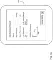
FIG. 3A showsremote device 300 having a touchscreen for a user to generate a safety protocol. Safety protocol includes personalization parameters that can be used to optimally configureinstrument 100 to increase patient safety by personalizing the tourniquet settings to the patient, the surgical procedure, or the surgeon.FIG. 3 A showsremote device 300 allowing the user to define the following personalization parameters: the name of the protocol; the maximum reference pressure limit; the alarm time limit; whether LOP measurement is required; whether LOP safety margin is for an adult or a pediatric patient; and the deflation sequence. In the preferred embodiment,remote device 300 is a smart-phone. -
FIG. 3B showsinstrument 100 withdisplay 122 andoptical scanner 124. After the generation of a safety protocol fromFIG. 3A ,remote device 300 shows machine-readableremote device symbol 302 corresponding toremote device 300, and machine-readable data 304 associated withremote device 300 that is indicative of at least one remote value of a personalization parameter of the developed safety protocol. - When a user positions
remote device 300 within the field of view ofoptical scanner 124, optical scanner contactlessly reads machine-readableremote device symbol 302 and machine-readable data 304. The field of view ofoptical scanner 124 is optimized to encompass a predetermined range of distances and a predetermined range of orientations relative tooptical scanner 124 to prevent inadvertent hazardous reading of a second remote device outside the predetermined ranges. -
Optical tourniquet interface 120 authenticates machine-readableremote device symbol 302 by matching it to stored authentication data. Once machine-readableremote device symbol 302 is authenticated,optical tourniquet interface 120 displays the values of the personalization parameters throughdisplay 122. The user may review the values of the personalization parameters and if they are considered safe and appropriate for the surgical procedure, the user can then selectively transfer the presented values of the personalization parameters to pressure controller 110 through safe transfer key 130. The user may also reject the transfer of the presented values of the personalization parameters to pressure controller 110 throughreject key 132. In this example, personalization parameters include information associated with a safety protocol named "pediatric protocol" such as the maximum reference pressure limit (400 mmHg), alarm time limit (60 min), whether LOP is required or not (yes), to use pediatric LOP safety margin, and to use a stepped-decrease deflation sequence, which may be used to facilitate the detection and closure of bleeding vessels. -
FIG. 4 depicts another example of the preferred embodiment in use. -
FIG. 4 showsinstrument 100 after a user activatedclinical summary key 134.Clinical summary key 134 may be activated by the user after a pressure control time period, such as one suitably long for a surgical procedure.Display 122 displays a graphical representation of plurality of pressure levels and alarm events corresponding to a plurality of times during the pressure control time period.Instrument 100 also displays machine-readableclinical data 402 that is indicative of the graphical representation. Machine-readableclinical data 402 may also be indicative of previously transferred values of personalization parameters.Remote personalization device 400 is shown withremote scanner 404 capable of reading machine-readableclinical data 402, and displaying the information contained in machine-readableclinical data 402 onremote display 406. In the preferred embodiment,remote device 400 is a smart phone. - The embodiments illustrated are not intended to be exhaustive or to limit the invention to the precise form disclosed. They are chosen and described in order to explain the principles of the invention and its application and practical use, and thereby enable others skilled in the art to utilize the invention.
- In view of the many possible embodiments to which the disclosed principles may be applied, it should be recognized that the illustrated embodiments are only preferred examples and should not be taken as limiting in scope. Rather, the scope of protection is defined by the following claims.
Claims (11)
- A tourniquet system having an optical tourniquet interface (120) for safe personalization, comprising:
a tourniquet cuff assembly (200) including:a tourniquet cuff (2, 206) having an inflatable bladder adapted for connection to a tourniquet instrument,a contactlessly-readable instrument symbol (202) identifying one type of tourniquet instrument from a plurality of types of tourniquet instruments, andcontactlessly-readable personalization data (204) representing a value of a personalization parameter for safe operation of the tourniquet cuff (2, 206) when connected to the identified type of tourniquet instrument; anda tourniquet instrument including:an optical tourniquet interface (120) communicating with a pressure controller (110) and operable for contactlessly reading and authenticating the contactlessly-readable instrument symbol (202) associated with the tourniquet cuff (2, 206) if it matches stored instrument authentication data, and further operable for contactlessly reading the contactlessly-readable personalization data (204) associated with the cuff (2, 206),wherein the optical tourniquet interface (120) is adapted to present in a form perceptible to a user the value of the personalization parameter if the contactlessly-readable instrument symbol (202) has been authenticated;a safe transfer key (130) which is operable by the user to manually selectively transfer the presented value of the personalization parameter to the pressure controller (110) only if the pressure controller (110) is inoperable; andthe pressure controller (110) releasably connectable to the tourniquet cuff (2, 206) and responsive to the transferred value of the personalization parameter, wherein the pressure controller (110) is operable for automatically controlling a level of pressure in the connected tourniquet cuff (2, 206) during a pressure control time period. - The tourniquet system of claim 1 wherein the tourniquet cuff (2, 206) is sterile, the system further comprising;a sterile connector (210) adapted for releasably connecting the sterile tourniquet cuff (2, 206) to the identified type of tourniquet instrument; andwherein the instrument symbol (202) and the personalization data (204) are carried at a location enabling contactless reading of the instrument symbol (202) and the personalization data (204) only if the sterile cuff assembly (200) is positioned by the user within a predetermined range of distances and within a predetermined range of orientations relative to the optical tourniquet interface (120).
- The tourniquet system of claim 1 or 2 wherein the optical tourniquet interface (120) includes a display (122) and wherein the optical tourniquet interface (120) is adapted to present the value of the personalization parameter to the user by displaying the value on the display (122).
- The tourniquet system of any preceding claim further including a reject key (132) which is operable by the user to manually selectively reject transfer of the presented value of the personalization parameter.
- The tourniquet system of claim 2 wherein the value of the personalization parameter indicates that the tourniquet cuff (2, 206) is adapted for automatic measurement of a Limb Occlusion Pressure of a patient by the identified tourniquet instrument.
- The tourniquet system of claim 2 or 5 wherein the value of the personalization parameter indicates that the tourniquet cuff (2, 206) is adapted for a pediatric patient.
- The tourniquet system of claim 2, 5 or 6, wherein the value of the personalization parameter indicates that the tourniquet cuff (2, 206) is adapted for intravenous regional anesthesia of a patient's limb.
- The tourniquet system of any preceding claim wherein the optical tourniquet interface (120) is further operable upon actuation of a clinical summary key by the user after the pressure control time period for generating and displaying contactlessly-readable clinical data indicative of at least one level of pressure corresponding to a time within the pressure control time period, and preferably wherein the contactlessly-readable clinical data is further indicative of the transferred presented value of the personalization parameter.
- The tourniquet system of any preceding claim further including a remote device (300, 400):wherein the optical tourniquet interface (120) is further operable for contactlessly reading and authenticating a contactlessly-readable remote device symbol (302) associated with the remote device (300, 400) if it matches stored authentication data corresponding to the remote device (300, 400); andwherein the optical tourniquet interface (120) is additionally operable for contactlessly reading contactlessly-readable data associated with the remote device (300, 400) that is indicative of a remote value of a personalization parameter;wherein the safe transfer key (130) is further adapted for enabling the user to safely transfer the remote value of the personalization parameter to the pressure controller (110) only if the contactlessly-readable remote device symbol (302) has been authenticated and only when the pressure controller (110) is inoperable; andwherein the pressure controller (110) is further responsive to the transferred remote value for safely controlling pressure in the connected tourniquet cuff during the pressure control time period.
- The tourniquet system of any preceding claim, wherein if the machine-readable instrument symbol (202) is not authenticated, the tourniquet instrument is configured to use a predetermined stored value for at least one personalization parameter.
- The tourniquet system of any preceding claim wherein the safe transfer key (130) further initiates operation of the pressure controller (110) upon the selective transfer of the presented value of the personalization parameter.
Applications Claiming Priority (3)
| Application Number | Priority Date | Filing Date | Title |
|---|---|---|---|
| US201962931102P | 2019-11-05 | 2019-11-05 | |
| US16/803,939 US10758247B1 (en) | 2019-11-05 | 2020-02-27 | Optical tourniquet interface for safe personalization |
| US16/937,488 US20210128172A1 (en) | 2019-11-05 | 2020-07-23 | Personalized tourniquet cuff assembly |
Publications (2)
| Publication Number | Publication Date |
|---|---|
| EP3818956A1 EP3818956A1 (en) | 2021-05-12 |
| EP3818956B1 true EP3818956B1 (en) | 2024-10-02 |
Family
ID=74188231
Family Applications (1)
| Application Number | Title | Priority Date | Filing Date |
|---|---|---|---|
| EP20205947.3A Active EP3818956B1 (en) | 2019-11-05 | 2020-11-05 | Optical tourniquet interface for safe personalization |
Country Status (6)
| Country | Link |
|---|---|
| US (1) | US20210128172A1 (en) |
| EP (1) | EP3818956B1 (en) |
| JP (1) | JP6896930B2 (en) |
| CN (1) | CN112773453B (en) |
| AU (1) | AU2020264357C1 (en) |
| CA (1) | CA3097325C (en) |
Family Cites Families (27)
| Publication number | Priority date | Publication date | Assignee | Title |
|---|---|---|---|---|
| US4469099A (en) | 1980-10-02 | 1984-09-04 | Western Clinical Engineering Ltd. | Pneumatic torniquet |
| US4479494A (en) | 1982-01-05 | 1984-10-30 | Western Clinical Engineering Ltd. | Adaptive pneumatic tourniquet |
| US4605010A (en) * | 1984-05-17 | 1986-08-12 | Western Clinical Engineering Ltd. | Pressurizing cuff |
| US5254087A (en) | 1990-01-29 | 1993-10-19 | Ivra Systems, Inc. | Tourniquet apparatus for intravenous regional anesthesia |
| US5556415A (en) | 1990-01-29 | 1996-09-17 | Mcewen; James A. | Physiologic tourniquet for intravenous regional anesthesia |
| US5855589A (en) | 1995-08-25 | 1999-01-05 | Mcewen; James A. | Physiologic tourniquet for intravenous regional anesthesia |
| US6682547B2 (en) | 2001-08-14 | 2004-01-27 | Mcewen James Allen | Tourniquet cuff with identification apparatus |
| US7331977B2 (en) * | 2001-08-14 | 2008-02-19 | Mcewen James A | Adaptive tourniquet cuff system |
| US7479154B2 (en) | 2005-05-05 | 2009-01-20 | Mcewen James A | Surgical tourniquet apparatus for measuring limb occlusion pressure |
| US7955352B2 (en) * | 2005-08-05 | 2011-06-07 | Western Clinical Engineering, Ltd | Surgical tourniquet cuff for limiting usage to improve safety |
| US20080243010A1 (en) * | 2007-03-30 | 2008-10-02 | General Electric Company | System and method for facilitating proper cuff use during non-invasive blood pressure measurement |
| US20090118628A1 (en) * | 2007-11-01 | 2009-05-07 | Triage Wireless, Inc. | System for measuring blood pressure featuring a blood pressure cuff comprising size information |
| US8425426B2 (en) * | 2007-11-09 | 2013-04-23 | Western Clinical Engineering, Ltd | Tourniquet apparatus for measuring limb occlusion pressure |
| WO2010150128A1 (en) * | 2009-06-22 | 2010-12-29 | Koninklijke Philips Electronics N.V. | Non-invasive blood pressure monitoring systems |
| US9241642B2 (en) * | 2012-02-16 | 2016-01-26 | Welch Allyn, Inc. | Systems and methods for monitoring a patient |
| DE102012110827A1 (en) * | 2012-11-12 | 2014-05-15 | Ulrich Gmbh & Co. Kg | Control device and control system for a tourniquet device |
| US10758130B2 (en) * | 2014-03-31 | 2020-09-01 | Welch Allyn, Inc. | Single site vitals |
| US9931126B2 (en) | 2014-07-10 | 2018-04-03 | Western Clinical Engineering Ltd. | Personalized tourniquet methods and apparatus |
| US10646231B2 (en) * | 2014-07-10 | 2020-05-12 | Western Clinical Engineering Ltd. | Personalized tourniquet for intermittent vascular occlusion |
| US9814467B2 (en) * | 2014-07-10 | 2017-11-14 | Western Clinical Engineering Ltd. | Personalized tourniquet apparatus |
| US9039730B1 (en) * | 2014-07-10 | 2015-05-26 | Western Clinical Engineering, Ltd. | Personalized tourniquet system having dual-purpose cuff |
| USRE50013E1 (en) * | 2014-07-25 | 2024-06-18 | Western Clinical Engineering Ltd. | Tourniquet system for personalized restriction of blood flow |
| CN204708922U (en) * | 2015-06-17 | 2015-10-21 | 田先丽 | Multifunctional hand wrist strap |
| US20180200140A1 (en) * | 2015-07-08 | 2018-07-19 | CellAegis Devices Inc. | Configurable system for performing remote ischemic conditioning (ric) on a subject |
| US20170086677A1 (en) * | 2015-09-30 | 2017-03-30 | General Electric Company | Apparatus and system to identify a blood pressure cuff size |
| US10667984B2 (en) * | 2015-12-18 | 2020-06-02 | Stryker Corporation | Systems and methods for operating patient therapy devices |
| US11576677B2 (en) * | 2017-12-28 | 2023-02-14 | Cilag Gmbh International | Method of hub communication, processing, display, and cloud analytics |
-
2020
- 2020-07-23 US US16/937,488 patent/US20210128172A1/en not_active Abandoned
- 2020-10-23 CA CA3097325A patent/CA3097325C/en active Active
- 2020-11-04 JP JP2020184062A patent/JP6896930B2/en active Active
- 2020-11-05 EP EP20205947.3A patent/EP3818956B1/en active Active
- 2020-11-05 CN CN202011222193.7A patent/CN112773453B/en active Active
- 2020-11-05 AU AU2020264357A patent/AU2020264357C1/en active Active
Also Published As
| Publication number | Publication date |
|---|---|
| US20210128172A1 (en) | 2021-05-06 |
| CN112773453B (en) | 2022-12-20 |
| JP6896930B2 (en) | 2021-06-30 |
| AU2020264357B1 (en) | 2021-04-01 |
| CN112773453A (en) | 2021-05-11 |
| JP2021074541A (en) | 2021-05-20 |
| CA3097325C (en) | 2021-05-04 |
| EP3818956A1 (en) | 2021-05-12 |
| CA3097325A1 (en) | 2021-01-20 |
| AU2020264357C1 (en) | 2021-10-07 |
Similar Documents
| Publication | Publication Date | Title |
|---|---|---|
| EP2398403B1 (en) | Integrated tourniquet system | |
| EP1876973B1 (en) | Surgical tourniquet apparatus for measuring limb occlusion pressure | |
| US8048105B2 (en) | Adaptive surgical tourniquet apparatus and method | |
| US8496001B2 (en) | Process and device for the automatic identification of breathing tubes | |
| CN101505813B (en) | medical device for extracorporeal blood treatment | |
| CA2704848C (en) | Improved tourniquet apparatus for measuring limb occlusion pressure | |
| US20100155465A1 (en) | Medical indication device and identification method | |
| US10758247B1 (en) | Optical tourniquet interface for safe personalization | |
| JP6436395B2 (en) | Injectable vascular access port with distinguishable markers for identification | |
| KR20080045165A (en) | Method and system for configuring a surgical device and entering data | |
| US20160008006A1 (en) | Personalized tourniquet methods and apparatus | |
| RU2622587C2 (en) | Control device and control system for hemostatic device | |
| CN112867437B (en) | Method and device for correcting blood pressure measurements performed at a measurement site | |
| AU2020264357C1 (en) | Optical tourniquet interface for safe personalization | |
| CN112040888B (en) | Personalized tourniquet for intermittent vascular occlusion | |
| EP3809984B1 (en) | Tourniquet with user-selectable safety protocols | |
| US20210153892A1 (en) | Epidural delivery device | |
| KR20020028599A (en) | Method for confirmation epidural space of the spinal cord and apparatus thereof |
Legal Events
| Date | Code | Title | Description |
|---|---|---|---|
| PUAI | Public reference made under article 153(3) epc to a published international application that has entered the european phase |
Free format text: ORIGINAL CODE: 0009012 |
|
| STAA | Information on the status of an ep patent application or granted ep patent |
Free format text: STATUS: THE APPLICATION HAS BEEN PUBLISHED |
|
| AK | Designated contracting states |
Kind code of ref document: A1 Designated state(s): AL AT BE BG CH CY CZ DE DK EE ES FI FR GB GR HR HU IE IS IT LI LT LU LV MC MK MT NL NO PL PT RO RS SE SI SK SM TR |
|
| RIN1 | Information on inventor provided before grant (corrected) |
Inventor name: MCEWEN, JAMES ALLEN |
|
| STAA | Information on the status of an ep patent application or granted ep patent |
Free format text: STATUS: REQUEST FOR EXAMINATION WAS MADE |
|
| 17P | Request for examination filed |
Effective date: 20211110 |
|
| RBV | Designated contracting states (corrected) |
Designated state(s): AL AT BE BG CH CY CZ DE DK EE ES FI FR GB GR HR HU IE IS IT LI LT LU LV MC MK MT NL NO PL PT RO RS SE SI SK SM TR |
|
| GRAP | Despatch of communication of intention to grant a patent |
Free format text: ORIGINAL CODE: EPIDOSNIGR1 |
|
| STAA | Information on the status of an ep patent application or granted ep patent |
Free format text: STATUS: GRANT OF PATENT IS INTENDED |
|
| INTG | Intention to grant announced |
Effective date: 20240711 |
|
| RAP3 | Party data changed (applicant data changed or rights of an application transferred) |
Owner name: WESTERN CLINICAL ENGINEERING LTD |
|
| RIN1 | Information on inventor provided before grant (corrected) |
Inventor name: PROKOPICH NICHOLAS ALEXANDER Inventor name: LIM REBECCA NICOLE Inventor name: LAU, TOM YU CHIA Inventor name: JAMESON, MICHAEL Inventor name: MCEWEN, JAMES ALLEN |
|
| GRAS | Grant fee paid |
Free format text: ORIGINAL CODE: EPIDOSNIGR3 |
|
| P01 | Opt-out of the competence of the unified patent court (upc) registered |
Free format text: CASE NUMBER: APP_43274/2024 Effective date: 20240724 |
|
| GRAA | (expected) grant |
Free format text: ORIGINAL CODE: 0009210 |
|
| STAA | Information on the status of an ep patent application or granted ep patent |
Free format text: STATUS: THE PATENT HAS BEEN GRANTED |
|
| AK | Designated contracting states |
Kind code of ref document: B1 Designated state(s): AL AT BE BG CH CY CZ DE DK EE ES FI FR GB GR HR HU IE IS IT LI LT LU LV MC MK MT NL NO PL PT RO RS SE SI SK SM TR |
|
| REG | Reference to a national code |
Ref country code: GB Ref legal event code: FG4D |
|
| REG | Reference to a national code |
Ref country code: CH Ref legal event code: EP |
|
| REG | Reference to a national code |
Ref country code: IE Ref legal event code: FG4D |
|
| REG | Reference to a national code |
Ref country code: DE Ref legal event code: R096 Ref document number: 602020038631 Country of ref document: DE |
|
| REG | Reference to a national code |
Ref country code: LT Ref legal event code: MG9D |
|
| REG | Reference to a national code |
Ref country code: NL Ref legal event code: MP Effective date: 20241002 |
|
| REG | Reference to a national code |
Ref country code: AT Ref legal event code: MK05 Ref document number: 1727931 Country of ref document: AT Kind code of ref document: T Effective date: 20241002 |
|
| PG25 | Lapsed in a contracting state [announced via postgrant information from national office to epo] |
Ref country code: NL Free format text: LAPSE BECAUSE OF FAILURE TO SUBMIT A TRANSLATION OF THE DESCRIPTION OR TO PAY THE FEE WITHIN THE PRESCRIBED TIME-LIMIT Effective date: 20241002 |
|
| PG25 | Lapsed in a contracting state [announced via postgrant information from national office to epo] |
Ref country code: NL Free format text: LAPSE BECAUSE OF FAILURE TO SUBMIT A TRANSLATION OF THE DESCRIPTION OR TO PAY THE FEE WITHIN THE PRESCRIBED TIME-LIMIT Effective date: 20241002 |
|
| PG25 | Lapsed in a contracting state [announced via postgrant information from national office to epo] |
Ref country code: IS Free format text: LAPSE BECAUSE OF FAILURE TO SUBMIT A TRANSLATION OF THE DESCRIPTION OR TO PAY THE FEE WITHIN THE PRESCRIBED TIME-LIMIT Effective date: 20250202 Ref country code: HR Free format text: LAPSE BECAUSE OF FAILURE TO SUBMIT A TRANSLATION OF THE DESCRIPTION OR TO PAY THE FEE WITHIN THE PRESCRIBED TIME-LIMIT Effective date: 20241002 Ref country code: PT Free format text: LAPSE BECAUSE OF FAILURE TO SUBMIT A TRANSLATION OF THE DESCRIPTION OR TO PAY THE FEE WITHIN THE PRESCRIBED TIME-LIMIT Effective date: 20250203 |
|
| PG25 | Lapsed in a contracting state [announced via postgrant information from national office to epo] |
Ref country code: FI Free format text: LAPSE BECAUSE OF FAILURE TO SUBMIT A TRANSLATION OF THE DESCRIPTION OR TO PAY THE FEE WITHIN THE PRESCRIBED TIME-LIMIT Effective date: 20241002 |
|
| PG25 | Lapsed in a contracting state [announced via postgrant information from national office to epo] |
Ref country code: BG Free format text: LAPSE BECAUSE OF FAILURE TO SUBMIT A TRANSLATION OF THE DESCRIPTION OR TO PAY THE FEE WITHIN THE PRESCRIBED TIME-LIMIT Effective date: 20241002 |
|
| PG25 | Lapsed in a contracting state [announced via postgrant information from national office to epo] |
Ref country code: ES Free format text: LAPSE BECAUSE OF FAILURE TO SUBMIT A TRANSLATION OF THE DESCRIPTION OR TO PAY THE FEE WITHIN THE PRESCRIBED TIME-LIMIT Effective date: 20241002 |
|
| PG25 | Lapsed in a contracting state [announced via postgrant information from national office to epo] |
Ref country code: NO Free format text: LAPSE BECAUSE OF FAILURE TO SUBMIT A TRANSLATION OF THE DESCRIPTION OR TO PAY THE FEE WITHIN THE PRESCRIBED TIME-LIMIT Effective date: 20250102 |
|
| PG25 | Lapsed in a contracting state [announced via postgrant information from national office to epo] |
Ref country code: AT Free format text: LAPSE BECAUSE OF FAILURE TO SUBMIT A TRANSLATION OF THE DESCRIPTION OR TO PAY THE FEE WITHIN THE PRESCRIBED TIME-LIMIT Effective date: 20241002 Ref country code: LV Free format text: LAPSE BECAUSE OF FAILURE TO SUBMIT A TRANSLATION OF THE DESCRIPTION OR TO PAY THE FEE WITHIN THE PRESCRIBED TIME-LIMIT Effective date: 20241002 Ref country code: GR Free format text: LAPSE BECAUSE OF FAILURE TO SUBMIT A TRANSLATION OF THE DESCRIPTION OR TO PAY THE FEE WITHIN THE PRESCRIBED TIME-LIMIT Effective date: 20250103 |
|
| PG25 | Lapsed in a contracting state [announced via postgrant information from national office to epo] |
Ref country code: PL Free format text: LAPSE BECAUSE OF FAILURE TO SUBMIT A TRANSLATION OF THE DESCRIPTION OR TO PAY THE FEE WITHIN THE PRESCRIBED TIME-LIMIT Effective date: 20241002 Ref country code: CZ Free format text: LAPSE BECAUSE OF FAILURE TO SUBMIT A TRANSLATION OF THE DESCRIPTION OR TO PAY THE FEE WITHIN THE PRESCRIBED TIME-LIMIT Effective date: 20241002 |
|
| PG25 | Lapsed in a contracting state [announced via postgrant information from national office to epo] |
Ref country code: RS Free format text: LAPSE BECAUSE OF FAILURE TO SUBMIT A TRANSLATION OF THE DESCRIPTION OR TO PAY THE FEE WITHIN THE PRESCRIBED TIME-LIMIT Effective date: 20250102 |
|
| REG | Reference to a national code |
Ref country code: CH Ref legal event code: PL |
|
| PG25 | Lapsed in a contracting state [announced via postgrant information from national office to epo] |
Ref country code: SM Free format text: LAPSE BECAUSE OF FAILURE TO SUBMIT A TRANSLATION OF THE DESCRIPTION OR TO PAY THE FEE WITHIN THE PRESCRIBED TIME-LIMIT Effective date: 20241002 |
|
| REG | Reference to a national code |
Ref country code: DE Ref legal event code: R097 Ref document number: 602020038631 Country of ref document: DE |
|
| PG25 | Lapsed in a contracting state [announced via postgrant information from national office to epo] |
Ref country code: MC Free format text: LAPSE BECAUSE OF FAILURE TO SUBMIT A TRANSLATION OF THE DESCRIPTION OR TO PAY THE FEE WITHIN THE PRESCRIBED TIME-LIMIT Effective date: 20241002 |
|
| PG25 | Lapsed in a contracting state [announced via postgrant information from national office to epo] |
Ref country code: DK Free format text: LAPSE BECAUSE OF FAILURE TO SUBMIT A TRANSLATION OF THE DESCRIPTION OR TO PAY THE FEE WITHIN THE PRESCRIBED TIME-LIMIT Effective date: 20241002 |
|
| PG25 | Lapsed in a contracting state [announced via postgrant information from national office to epo] |
Ref country code: LU Free format text: LAPSE BECAUSE OF NON-PAYMENT OF DUE FEES Effective date: 20241105 |
|
| REG | Reference to a national code |
Ref country code: CH Ref legal event code: PL |
|
| PG25 | Lapsed in a contracting state [announced via postgrant information from national office to epo] |
Ref country code: EE Free format text: LAPSE BECAUSE OF FAILURE TO SUBMIT A TRANSLATION OF THE DESCRIPTION OR TO PAY THE FEE WITHIN THE PRESCRIBED TIME-LIMIT Effective date: 20241002 |
|
| PG25 | Lapsed in a contracting state [announced via postgrant information from national office to epo] |
Ref country code: CH Free format text: LAPSE BECAUSE OF NON-PAYMENT OF DUE FEES Effective date: 20241130 |
|
| PG25 | Lapsed in a contracting state [announced via postgrant information from national office to epo] |
Ref country code: RO Free format text: LAPSE BECAUSE OF FAILURE TO SUBMIT A TRANSLATION OF THE DESCRIPTION OR TO PAY THE FEE WITHIN THE PRESCRIBED TIME-LIMIT Effective date: 20241002 |
|
| PG25 | Lapsed in a contracting state [announced via postgrant information from national office to epo] |
Ref country code: SK Free format text: LAPSE BECAUSE OF FAILURE TO SUBMIT A TRANSLATION OF THE DESCRIPTION OR TO PAY THE FEE WITHIN THE PRESCRIBED TIME-LIMIT Effective date: 20241002 |
|
| PG25 | Lapsed in a contracting state [announced via postgrant information from national office to epo] |
Ref country code: IT Free format text: LAPSE BECAUSE OF FAILURE TO SUBMIT A TRANSLATION OF THE DESCRIPTION OR TO PAY THE FEE WITHIN THE PRESCRIBED TIME-LIMIT Effective date: 20241002 |
|
| PLBE | No opposition filed within time limit |
Free format text: ORIGINAL CODE: 0009261 |
|
| STAA | Information on the status of an ep patent application or granted ep patent |
Free format text: STATUS: NO OPPOSITION FILED WITHIN TIME LIMIT |
|
| REG | Reference to a national code |
Ref country code: BE Ref legal event code: MM Effective date: 20241130 |
|
| PG25 | Lapsed in a contracting state [announced via postgrant information from national office to epo] |
Ref country code: SE Free format text: LAPSE BECAUSE OF FAILURE TO SUBMIT A TRANSLATION OF THE DESCRIPTION OR TO PAY THE FEE WITHIN THE PRESCRIBED TIME-LIMIT Effective date: 20241002 |
|
| 26N | No opposition filed |
Effective date: 20250703 |
|
| PG25 | Lapsed in a contracting state [announced via postgrant information from national office to epo] |
Ref country code: BE Free format text: LAPSE BECAUSE OF NON-PAYMENT OF DUE FEES Effective date: 20241130 |
|
| PG25 | Lapsed in a contracting state [announced via postgrant information from national office to epo] |
Ref country code: IE Free format text: LAPSE BECAUSE OF NON-PAYMENT OF DUE FEES Effective date: 20241105 |
|
| PGFP | Annual fee paid to national office [announced via postgrant information from national office to epo] |
Ref country code: DE Payment date: 20251007 Year of fee payment: 6 |
|
| PGFP | Annual fee paid to national office [announced via postgrant information from national office to epo] |
Ref country code: GB Payment date: 20251016 Year of fee payment: 6 |
|
| PGFP | Annual fee paid to national office [announced via postgrant information from national office to epo] |
Ref country code: FR Payment date: 20251008 Year of fee payment: 6 |
|
| PG25 | Lapsed in a contracting state [announced via postgrant information from national office to epo] |
Ref country code: HU Free format text: LAPSE BECAUSE OF FAILURE TO SUBMIT A TRANSLATION OF THE DESCRIPTION OR TO PAY THE FEE WITHIN THE PRESCRIBED TIME-LIMIT; INVALID AB INITIO Effective date: 20201105 |
|
| PG25 | Lapsed in a contracting state [announced via postgrant information from national office to epo] |
Ref country code: CY Free format text: LAPSE BECAUSE OF FAILURE TO SUBMIT A TRANSLATION OF THE DESCRIPTION OR TO PAY THE FEE WITHIN THE PRESCRIBED TIME-LIMIT; INVALID AB INITIO Effective date: 20201105 |