EP3818512B1 - Obstacle avoidance in autonomous vehicles - Google Patents
Obstacle avoidance in autonomous vehicles Download PDFInfo
- Publication number
- EP3818512B1 EP3818512B1 EP19830065.9A EP19830065A EP3818512B1 EP 3818512 B1 EP3818512 B1 EP 3818512B1 EP 19830065 A EP19830065 A EP 19830065A EP 3818512 B1 EP3818512 B1 EP 3818512B1
- Authority
- EP
- European Patent Office
- Prior art keywords
- vehicle
- point
- turn
- range values
- real
- Prior art date
- Legal status (The legal status is an assumption and is not a legal conclusion. Google has not performed a legal analysis and makes no representation as to the accuracy of the status listed.)
- Active
Links
Images


Classifications
-
- B—PERFORMING OPERATIONS; TRANSPORTING
- B60—VEHICLES IN GENERAL
- B60W—CONJOINT CONTROL OF VEHICLE SUB-UNITS OF DIFFERENT TYPE OR DIFFERENT FUNCTION; CONTROL SYSTEMS SPECIALLY ADAPTED FOR HYBRID VEHICLES; ROAD VEHICLE DRIVE CONTROL SYSTEMS FOR PURPOSES NOT RELATED TO THE CONTROL OF A PARTICULAR SUB-UNIT
- B60W30/00—Purposes of road vehicle drive control systems not related to the control of a particular sub-unit, e.g. of systems using conjoint control of vehicle sub-units
- B60W30/08—Active safety systems predicting or avoiding probable or impending collision or attempting to minimise its consequences
- B60W30/09—Taking automatic action to avoid collision, e.g. braking and steering
-
- G—PHYSICS
- G08—SIGNALLING
- G08G—TRAFFIC CONTROL SYSTEMS
- G08G1/00—Traffic control systems for road vehicles
- G08G1/16—Anti-collision systems
- G08G1/165—Anti-collision systems for passive traffic, e.g. including static obstacles, trees
-
- G—PHYSICS
- G05—CONTROLLING; REGULATING
- G05D—SYSTEMS FOR CONTROLLING OR REGULATING NON-ELECTRIC VARIABLES
- G05D1/00—Control of position, course, altitude or attitude of land, water, air or space vehicles, e.g. using automatic pilots
- G05D1/02—Control of position or course in two dimensions
- G05D1/021—Control of position or course in two dimensions specially adapted to land vehicles
- G05D1/0231—Control of position or course in two dimensions specially adapted to land vehicles using optical position detecting means
- G05D1/0238—Control of position or course in two dimensions specially adapted to land vehicles using optical position detecting means using obstacle or wall sensors
- G05D1/024—Control of position or course in two dimensions specially adapted to land vehicles using optical position detecting means using obstacle or wall sensors in combination with a laser
-
- B—PERFORMING OPERATIONS; TRANSPORTING
- B60—VEHICLES IN GENERAL
- B60W—CONJOINT CONTROL OF VEHICLE SUB-UNITS OF DIFFERENT TYPE OR DIFFERENT FUNCTION; CONTROL SYSTEMS SPECIALLY ADAPTED FOR HYBRID VEHICLES; ROAD VEHICLE DRIVE CONTROL SYSTEMS FOR PURPOSES NOT RELATED TO THE CONTROL OF A PARTICULAR SUB-UNIT
- B60W30/00—Purposes of road vehicle drive control systems not related to the control of a particular sub-unit, e.g. of systems using conjoint control of vehicle sub-units
- B60W30/08—Active safety systems predicting or avoiding probable or impending collision or attempting to minimise its consequences
-
- B—PERFORMING OPERATIONS; TRANSPORTING
- B60—VEHICLES IN GENERAL
- B60W—CONJOINT CONTROL OF VEHICLE SUB-UNITS OF DIFFERENT TYPE OR DIFFERENT FUNCTION; CONTROL SYSTEMS SPECIALLY ADAPTED FOR HYBRID VEHICLES; ROAD VEHICLE DRIVE CONTROL SYSTEMS FOR PURPOSES NOT RELATED TO THE CONTROL OF A PARTICULAR SUB-UNIT
- B60W30/00—Purposes of road vehicle drive control systems not related to the control of a particular sub-unit, e.g. of systems using conjoint control of vehicle sub-units
- B60W30/18—Propelling the vehicle
- B60W30/18009—Propelling the vehicle related to particular drive situations
-
- B—PERFORMING OPERATIONS; TRANSPORTING
- B60—VEHICLES IN GENERAL
- B60W—CONJOINT CONTROL OF VEHICLE SUB-UNITS OF DIFFERENT TYPE OR DIFFERENT FUNCTION; CONTROL SYSTEMS SPECIALLY ADAPTED FOR HYBRID VEHICLES; ROAD VEHICLE DRIVE CONTROL SYSTEMS FOR PURPOSES NOT RELATED TO THE CONTROL OF A PARTICULAR SUB-UNIT
- B60W50/00—Details of control systems for road vehicle drive control not related to the control of a particular sub-unit, e.g. process diagnostic or vehicle driver interfaces
- B60W50/06—Improving the dynamic response of the control system, e.g. improving the speed of regulation or avoiding hunting or overshoot
-
- B—PERFORMING OPERATIONS; TRANSPORTING
- B60—VEHICLES IN GENERAL
- B60W—CONJOINT CONTROL OF VEHICLE SUB-UNITS OF DIFFERENT TYPE OR DIFFERENT FUNCTION; CONTROL SYSTEMS SPECIALLY ADAPTED FOR HYBRID VEHICLES; ROAD VEHICLE DRIVE CONTROL SYSTEMS FOR PURPOSES NOT RELATED TO THE CONTROL OF A PARTICULAR SUB-UNIT
- B60W60/00—Drive control systems specially adapted for autonomous road vehicles
- B60W60/001—Planning or execution of driving tasks
- B60W60/0015—Planning or execution of driving tasks specially adapted for safety
-
- G—PHYSICS
- G05—CONTROLLING; REGULATING
- G05D—SYSTEMS FOR CONTROLLING OR REGULATING NON-ELECTRIC VARIABLES
- G05D1/00—Control of position, course, altitude or attitude of land, water, air or space vehicles, e.g. using automatic pilots
- G05D1/0055—Control of position, course, altitude or attitude of land, water, air or space vehicles, e.g. using automatic pilots with safety arrangements
-
- G—PHYSICS
- G05—CONTROLLING; REGULATING
- G05D—SYSTEMS FOR CONTROLLING OR REGULATING NON-ELECTRIC VARIABLES
- G05D1/00—Control of position, course, altitude or attitude of land, water, air or space vehicles, e.g. using automatic pilots
- G05D1/02—Control of position or course in two dimensions
- G05D1/021—Control of position or course in two dimensions specially adapted to land vehicles
- G05D1/0212—Control of position or course in two dimensions specially adapted to land vehicles with means for defining a desired trajectory
- G05D1/0214—Control of position or course in two dimensions specially adapted to land vehicles with means for defining a desired trajectory in accordance with safety or protection criteria, e.g. avoiding hazardous areas
-
- G—PHYSICS
- G08—SIGNALLING
- G08C—TRANSMISSION SYSTEMS FOR MEASURED VALUES, CONTROL OR SIMILAR SIGNALS
- G08C25/00—Arrangements for preventing or correcting errors; Monitoring arrangements
- G08C25/02—Arrangements for preventing or correcting errors; Monitoring arrangements by signalling back receiving station to transmitting station
-
- B—PERFORMING OPERATIONS; TRANSPORTING
- B60—VEHICLES IN GENERAL
- B60W—CONJOINT CONTROL OF VEHICLE SUB-UNITS OF DIFFERENT TYPE OR DIFFERENT FUNCTION; CONTROL SYSTEMS SPECIALLY ADAPTED FOR HYBRID VEHICLES; ROAD VEHICLE DRIVE CONTROL SYSTEMS FOR PURPOSES NOT RELATED TO THE CONTROL OF A PARTICULAR SUB-UNIT
- B60W2420/00—Indexing codes relating to the type of sensors based on the principle of their operation
- B60W2420/40—Photo, light or radio wave sensitive means, e.g. infrared sensors
- B60W2420/403—Image sensing, e.g. optical camera
-
- B—PERFORMING OPERATIONS; TRANSPORTING
- B60—VEHICLES IN GENERAL
- B60W—CONJOINT CONTROL OF VEHICLE SUB-UNITS OF DIFFERENT TYPE OR DIFFERENT FUNCTION; CONTROL SYSTEMS SPECIALLY ADAPTED FOR HYBRID VEHICLES; ROAD VEHICLE DRIVE CONTROL SYSTEMS FOR PURPOSES NOT RELATED TO THE CONTROL OF A PARTICULAR SUB-UNIT
- B60W2420/00—Indexing codes relating to the type of sensors based on the principle of their operation
- B60W2420/40—Photo, light or radio wave sensitive means, e.g. infrared sensors
- B60W2420/408—Radar; Laser, e.g. lidar
Definitions
- the presently disclosed subject matter relates to unmanned vehicles, and more particularly to obstacle avoidance by unmanned vehicles.
- an unmanned ground vehicle also referred to as an uncrewed vehicle
- UUV unmanned ground vehicle
- the vehicle can, in some cases, carry passengers, e.g. operators that cannot see the surrounding environment and/or maneuver the vehicle.
- VFH vector field histogram
- VFH+ and VFH* vector field histogram
- Minguez J. et. al describe extending collision avoidance methods to consider the shape, kinematics and dynamics of a mobile robot in IEEE Transactions on robotics (2009) vol. 25, no. 2, p. 367-381 .
- Obstacle avoidance of autonomous vehicles is a challenging task in general, particularly when navigating in an area which is densely crowded with obstacles, leaving the vehicle with limited maneuvering space. In such scenarios, the vehicle is many times required to maneuver very close to obstacles, and therefore an accurate method of detecting obstacles and controlling the vehicle is needed. Furthermore, this challenge becomes even more demanding when the vehicle is characterized by an asymmetric contour, and, accordingly, its ability to safely traverse through an area depends on its direction of movement.
- point-turn or “rotation” as used herein refers to a turn where the center of rotation is located along a driving symmetry axis, which is a line intersecting a first driving element axis on one side of the vehicle, and a second driving element axis on the other side of the vehicle.
- driving element refers to a device or system used for driving the vehicle and includes, for example, wheels and tracks. During a point-turn the driving element on one side of the vehicle turns in one direction (e.g. forward) and the other driving element on the other side of the vehicle turns in the opposite direction (e.g.
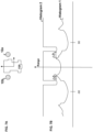
- FIGs. 1a-1c are schematic illustrations demonstrating point-turns. Illustration 1a, 1a and 1c each show a vehicle ( 10 ) with a left driving element (e.g. left tracks LT ) and right driving element (right tracks RT). The arrows on the side of the driving element indicate, by way of example, the direction of motion of each respective driving element.
- the broken line (SA) indicates a driving symmetry axis crossing the vehicle and extending from a left driving axis (L-DA) to a right driving axis (R-DA); e.g.
- the solid black circle indicates the rotation point of the vehicle (RP).
- the distance of each rotation point from the vehicle's driving elements is proportional to the velocities of the driving element on each side.
- V 1 /V 2 is proportional to D 1 /D 2
- Fig. 1a is an example where both the right tracks RT and the left tracks LT move at the same velocity (as indicated by the arrows on each side that have the same length), in which case the vehicle rotates about a rotation point located at the center of the symmetry axis at a substantially equal distance from the left driving element and the right driving element.
- the circle indicated by the broken line shows the turning radius ( TR ) of the tracks.
- Fig. 1b is an example where the velocity of the left tracks LT is zero and the velocity of the right tracks RT is greater than zero (as indicated by the absence of an arrow on the left side), in which case the vehicle rotates about a rotation point located on the left tracks, i.e. the distance from the rotation point to the left tracks is zero.
- Fig. 1c is an example where the velocity of the left tracks LT is 20% of the velocity of the right tracks RT.
- the relative turning radiuses of the driving element on each side is also shown as TR LEFT and TR RIGHT .
- Figs. 2Aa-2Ac show schematic illustrations demonstrating rotation maneuver of a vehicle characterized by an asymmetric perimeter.
- Fig. 2Aa shows a vehicle having its front end pointing to the north, as indicated by the dark arrow on the back of the vehicle.
- the contour of vehicle 10 is characterized by a greater protrusion on the left side as compared to the right side.
- the asymmetric contour of the vehicle can result for example, from the structure of the vehicle (e.g. a vehicle carrying an implement protruding from one of its sides) or from a cargo being loaded onto the vehicle in an asymmetric manner. Assuming the vehicle needs to turn back to the direction it came from, the vehicle can only make a point-turn (or reverse backwards), or otherwise it would collide with the obstacles surrounding the vehicle (wall 11 and rock 12 ).
- the vehicle can make a point-turn either to the left or to the right. If the point-turn is made to the left, the vehicle would not collide with the boulder 12 ( Fig. 2Ab ). If, on the other hand, the point-turn is made to the right, the vehicle would collide with the boulder 12 (as indicated by arrow 13 in Fig. 2Ac ). In other examples, the vehicle may not be able to make a point-turn to either side without colliding with an obstacle, and in such a case it would be compelled to drive backwards (in reverse) until it reaches a position where it can rotate.
- Figs. 2Ba-2Bc are schematic illustrations demonstrating rotation maneuver of a vehicle characterized by an asymmetric perimeter.
- A initial position
- the vehicle is positioned with its front end pointing to the north, as indicated by the dark arrow on the back of the vehicle.
- the shorter maneuver for positioning the vehicle in the desired direction would be taking a right turn
- a longer maneuver for positioning the vehicle in the desired direction would be taking a left turn.
- a right turn would result in a collision with boulder 12 while a left turn as shown in Fig. 2Bc would avoid such a collision.
- taking the left turn is preferable in this case.
- the presently disclosed subject matter includes a computerized method and a control system mountable on a vehicle for autonomously controlling the vehicle and enabling to execute a point-turn while avoiding collision with nearby obstacles. More specifically, the proposed technique enables an autonomous vehicle, characterized by an asymmetric contour, to execute a collision free point-turn, in an area crowded with obstacles. The disclosed method enables execution of a point turn quickly, without requiring the vehicle to stop.
- a computer implemented method of autonomously maneuvering a vehicle during a point-turn comprising:
- the method according to this aspect of the presently disclosed subject matter can optionally comprise one or more of features (i) to (xvi) listed below, in any technically possible combination or permutation:
- an unmanned vehicle comprising:
- a system mountable on an unmanned vehicle comprising:
- a computer program product comprising a computer readable storage medium retaining program instructions, the program instructions, when read by a processor, cause the processor to perform a method of autonomously maneuvering a vehicle during a point-turn, comprising:
- system, unmanned vehicle and computer program produce, of the presently disclosed subject matter can optionally comprise one or more of features (i) to (xvi) listed above, mutatis mutandis, in any technically possible combination or permutation.
- processing unit e.g. processing unit 116 described below with reference to Fig. 3
- computer control unit
- control unit or the like should be expansively construed to include any kind of hardware electronic device with data a processing circuitry that includes one or more computer processors (e.g., a Central Processing Unit (CPU), a microprocessor, an electronic circuit, an Integrated Circuit (IC), firmware written for or ported to a specific processor such as digital signal processor (DSP), a microcontroller, a field programmable gate array (FPGA), an application specific integrated circuit (ASIC), etc.) and is capable of executing computer instructions as disclosed herein below (e.g. loaded on a computer memory operatively connected to the processing circuitry).
- processors e.g., a Central Processing Unit (CPU), a microprocessor, an electronic circuit, an Integrated Circuit (IC), firmware written for or ported to a specific processor such as digital signal processor (DSP), a microcontroller, a field programmable gate array (FPGA), an
- Fig. 3 illustrates a general schematic diagram of components of the disclosed system in accordance with some examples. Elements in Fig. 3 can be made up of a combination of software and hardware and/or firmware that performs the functions as defined and explained herein. It should be understood that in other examples of the presently disclosed subject matter, the system may comprise fewer, more, and/or different elements than those shown in Fig. 3 . Accordingly, the specific structure shown in Fig. 3 is provided by way of example and should not be construed as limiting. For example, processing unit 116 can be otherwise divided into a different combination of modules than those shown in Fig. 3 for performing the same operations.
- Some operations in accordance with the teachings herein may be performed by a computer specially constructed for the desired purposes or by a general-purpose computer specially configured for the desired purpose by a computer program stored in a computer readable storage medium.
- scanning device should be expansively construed to include any kind of device configured to determine a range from the device to a specific direction relative to the device.
- scanning devices include, but are not limited to: laser scanners (including LIDAR), RADAR, images sensor, sonar, etc.
- a scanning device can scan for example, 360° on a plane surrounding the device, or at some other smaller scanning angle (e.g. 180°).
- the scanning device can scan a sphere or part thereof around the scanning device.
- a scanning device can provide information for generating a 3 dimensional map of the scanned area.
- a 2.5 dimensional map may be generated, as detailed below.
- the term “substantially” is used herein to imply the possibility of variations in values within an acceptable range. According to one example, the term “substantially” is used to imply a variation of 10% over or under a prescribed value. According to one example, the term “substantially” is used to imply a variation of 5% over or under a prescribed value. According to one example, the term “substantially” is used to imply a variation of 2.5% over or under a prescribed value. According to one example, the term “substantially” is used to imply a variation of 1.25 % over or under a prescribed value.
- FIG. 3 showing a schematic block diagram of a navigation system 102 mounted on a UGV 100, in accordance with some examples of the presently disclosed subject matter.
- system 102 can be installed on UGV 100. It will be appreciated that system 102 can comprise components, some of which may also serve purposes other than those described herein, and that components of system 102 may be located at different places on UGV 100.
- Navigation system 102 can comprise or be otherwise operatively connected to one or more than one scanning device 104 mounted on-board the vehicle configured to scan an area surrounding the vehicle, and provide scanning output data.
- Scanning output data includes information indicative of the location of objects relative to the vehicle in a multiplicity of directions around the vehicle.
- the scanning device continuously scans the area surrounding the vehicle, and a range map is dynamically generated based on the scanning output data, indicating the real-time position of the vehicle relative to objects in the traversed area.
- System 102 can further comprise or be otherwise operatively connected to various navigation devices 110 such as inertial navigation system (INS) and GPS receiver.
- navigation devices 110 such as inertial navigation system (INS) and GPS receiver.
- INS inertial navigation system
- GPS receiver GPS receiver
- System 102 can further comprise or be otherwise operatively connected to vehicle control sub-system 108 that includes for example, steering control unit for controlling the steering of the vehicle, gear control unit for control the gear of the vehicle during driving, throttle control unit for controlling accelerating and decelerating, etc.
- Vehicle control sub-system 108 is configured in some examples to receive vehicle navigation instructions and in response generate instructions (e.g. steering commands) for controlling the movement of the UGV 100 according to the navigation instructions.
- System 102 can further comprise or be otherwise operatively connected to one or more computer data storage devices 112 for storing information such as maps (including the range map), information on obstacles, navigation instructions, or the like. As explained further below, data storage devices 112 can be also used for storing vehicle-contour range values.
- Navigation system 102 further comprises or is otherwise operatively connected to one or more processing units for controlling and executing various operations, as disclosed herein.
- Each processing unit comprises a respective processing circuitry comprising at least one computer processor which can be operatively connected to a computer-readable storage device having computer instructions stored thereon to be executed by the computer processor.
- different elements in system 102 can be implemented each as a dedicated processing circuitry comprising dedicated computer processor and computer data-storage for executing specific operations.
- one or more elements can be part of a common processing circuitry configured to execute operations according to instructions stored in the elements.
- system 102 can comprise processing unit 116 configured to execute several modules, which can be implemented in some examples as instructions stored on a non-transitory computer-readable medium.
- modules are shown and referred to herein as comprised in the processor.
- part of the processing can be performed by a computer located remotely from the UGV and configured to receive input data from system 102 and provide the processing output to the system over a communication link.
- Figs. 4a and 4b are a schematic illustrations showing two examples of vehicle 10 from top-view and a multiplicity of lines extending from a rotation point RT towards the edges of the vehicle (marked by bold line 17 ).
- Fig. 4a is an example where the rotation point is located at the center of the driving symmetry axis
- Fig. 4b is an example where the rotation point RT is located off-center of the driving symmetry axis.
- Each line indicates a distance from a rotation point to a vehicle edge in a specific direction.
- the number of ranges can vary according to the desired angular resolution, e.g. 180 range values for a 2° angular resolution, 360 range values for a 1° resolution, 720 range values for 0.5° resolution (range determined for every half an angle), and so forth.
- the rotation point is located somewhere on the symmetry axis of the left and right driving element. The exact location of a rotation point along the axis depends on the relative velocity of a driving element on one side and a driving element on the opposite side. Or, in other words, given a certain velocity of a driving element on one side and a certain velocity of a driving element on the opposite side, the vehicle rotates around a certain rotation point.
- the vehicle-contour range values depend on the specific geometrical characteristics of each vehicle and therefore differ in different types of vehicles.
- the vehicle-contour range values can also depend on auxiliary equipment (e.g. implements or cargo) loaded on the vehicle if such equipment protrudes beyond the edges of the vehicle.
- processing unit 116 is configured to receive the scanning output data and generate a range map (e.g. by range map generation module 130) comprising at least one set of plurality of real-time range values (also referred to herein as "real-time obstacle range values").
- range map generation module 130 comprising at least one set of plurality of real-time range values (also referred to herein as "real-time obstacle range values").
- Each real-time range values is a range measured from a certain rotation point in a certain direction around the vehicle, possibly indicating a nearby obstacle.
- processing unit 116 is configured to calculate range difference values (e.g. by range differences calculator 132 ).
- range difference values refers to the differences between the real-time range values and their corresponding vehicle-contour range values.
- processing unit 116 is configured to calculate in real-time, the differences between real-time range values determined based on real-time scanning output and the vehicle contour range values, and determine the difference range values.
- Processing unit 116 can be further configured (e.g. by point-turn determination module 134 ) to determine, based on the calculated differences, conditions for making a point-turn.
- Processing unit 116 can be further configured (e.g. by point-turn command generation module 136 ) to generate a point-turn command and transmit the command to the vehicle control sub-system where it is executed.
- FIG. 5 showing a flowchart of operations carried out according to some examples of the presently disclosed subject matter. Operations are described below with reference to elements in Fig. 3 , however this is done by way of example only and should not be construed as limiting, and it should be understood that other system designs providing the same functionality are contemplated within the scope of this disclosure.
- vehicle-contour range values are obtained and stored in a computer data storage device in system 102.
- This stage can be executed, in some examples, as a preparatory stage before operation of the UGV and/or execution of a point-turn.
- the vehicle-contour range values can be determined by measuring the ranges from a rotation point RP to the edges of the vehicle in a multiplicity of directions.
- vehicle-contour range values can be uploaded (e.g. from a remote library over a communication link) and stored in system 102 in storage device ( 112 ).
- the library can include, for example, vehicle-contour range values of various types of vehicles and provide the needed information to system 102 when installed on a vehicle of a certain type.
- vehicle-contour range values of a given vehicle can include a plurality (denoted by 'K ' ) of sets of values, each set corresponding to a rotation point at different locations along the driving symmetry axis.
- K can be any number equal to or greater than 1.
- a greater number of optional rotation points i.e. greater K value increases the flexibility when maneuvering the vehicle, as it provides greater possibilities when performing a point-turn, and a greater ability to adapt to the real-time environment.
- system 102 is configured to determine the vehicle-contour range values.
- processor 116 can be configured to receive scanning output data (including for example, output data generated by a laser scanner or a camera), process the output data, determine the vehicle range values, and store the vehicle range values in the data storage device.
- a reflective material can be placed around the edges of the vehicle (e.g. along line 17 in Fig. 4 ) and a scanning device 104 (e.g. laser or LIDAR) positioned on board the vehicle can be used for determining the contour range values based on the reflections received from the edges.
- a set of vehicle contour range values can be determined for each of one or more rotation points along the driving symmetry axis of the vehicle, based on the offset location of the scanning device and a respective rotation point, using geometrical principles.
- Fig. 9 demonstrates calculation of a range ( R B ) from rotation point RP to a point P on vehicle edge based on range from sensor 15 to point P.
- Angle ⁇ B is the angle at the rotation point between the longitudinal axis of the vehicle and point P.
- distances ⁇ X and ⁇ Y which are the right angle distances between the RP and the sensor, can be pre-stored (e.g. in a computer storage device 112 ) and be made available to processing unit 116. If more than one optional rotation point is used for each rotation point a respective ⁇ X K and ⁇ Y K can be stored and made available during execution of a point turn.
- an image of the vehicle can be taken from a top-view point in order to obtain an image showing the perimeter of the vehicle.
- Image processing can be then implemented on the image for determining vehicle-contour range values.
- the image can be captured by a camera positioned above the vehicle.
- a camera 124
- a drone or some other airborne device carrying a camera can be used to fly over the vehicle and capture the image.
- Other methods can also be used e.g. using a camera mounted on a crane positioned above the vehicle or determining vehicle-contour range values during manufacturing and/or assembly of the UGV.
- system 102 can comprise an image processing unit (e.g. image processor 128 in processing unit 116 ) configured for processing the image and determining the vehicle-contour range values therefrom.
- image processing unit e.g. image processor 128 in processing unit 116
- vehicle-contour range values are repeatedly (e.g. periodically) updated in order to monitor for any changes in the contour of the vehicle, e.g. in case cargo is removed or added, thus changing the outline of the vehicle.
- the process of determining vehicle-contour range values can be initiated while the vehicle is operating in the field, either responsive to an explicit command or autonomously e.g. in response to a certain event or as a periodically repeating process.
- vehicle-contour range values of a given vehicle can include a plurality of sets of values, where each set corresponds to a rotation point located at different locations along the driving symmetry axis.
- the scanning device is operated to scan an area around the vehicle (perform a scanning operation) and generate scanning output data, comprising readings of distances from the UGV to objects in multiple directions.
- the scanner is operated to provide the readings repeatedly, at a rate depending, inter alia, on the device capabilities, user settings, or the like.
- the readings may be received for a full cycle (360°) around the device, or for a smaller angle, such as 180°, 270°, or the like.
- the readings may be received at a predefined resolution, such as every 0.5°, every 1°, every 2°, or the like, horizontally and vertically. It will be appreciated that scanning output data may be received from multiple scanners operatively connected to the UGV.
- the scanning output data is transmitted to a computer processor (e.g. processing unit 116 ), where it is processed.
- a range map comprising the real-time range values are determined (e.g. by range map generation module 130 ). These values are calculated based on the scanning device output data and the location of each rotation point relative to that of the scanning device. Namely, the raw range values obtained by the scanning device are transformed, using geometrical principles, for calculating the range values from various rotation points along the driving symmetry axis.
- Fig. 10 demonstrates calculation of range ( R T ) from rotation point RP to detected obstacle 12 based on range from sensor 15 to obstacle 12.
- Angle ⁇ T is the angle at the rotation point between the longitudinal of the vehicle and the detected object.
- distances ⁇ X and ⁇ Y which are the right angle distances between the RP and the sensor, can be pre-stored in a computer storage device 112 and made accessible to processing unit 116. If more than one optional rotation point is used for each rotation point, a respective ⁇ X K and ⁇ Y K can be stored and made available.
- differences between real-time range values and vehicle-contour range values are determined (e.g. by range differences calculator 132 in processioning unit 116 ).
- the difference between each one (denoted i ) of a plurality of real-time range values (denoted M ) and each one (denoted j ) of a plurality of vehicle-contour range values (denoted M ) is calculated. This calculation provides M ⁇ N range-difference values. Assuming, for example, both M and N equal 360, the result would be 360 2 range-difference values.
- the difference between a given real-time range value at an angle ⁇ Ti (indicative of a range between a rotation point RT d and a detected object) and a corresponding vehicle-contour range value at an angle ⁇ Bi (indicative of a range between the same rotation point RT d and the vehicle edge) is determined.
- each set of real-time range values may include 360 values measured in 1° resolution, that coincide with azimuth 0 (North). In other examples, some difference (e.g. 0.25-0.5 of a degree) between angle in the two sets may be allowed (i.e. ⁇ Ti ⁇ ⁇ Bi ).
- a filtering process is executed (e.g. by range value filter 138 in processing unit 116 ), where the real-time range values are filtered and only range values which are below a certain threshold value (denoted M', where M' ⁇ M) are compared with the vehicle-contour range values.
- the threshold is selected such that real-time range values which are above the threshold do not indicate a collision risk during a point-turn, and, accordingly, can be ignored.
- the filtering helps to reduce the processing intensity and time of the calculation.
- vehicle-contour range values of a given vehicle can include a plurality of sets of values.
- M ⁇ N range-difference values or less are calculated.
- At block 509 it is determined (e.g. by point turn determination module 134) whether there is an allowed point- turn (or more than one).
- Range-difference values are processed in order to determine whether a point-turn is allowed, e.g. whether a point-turn can be made without colliding into an obstacle or without a considerable risk of collision. Collision risk can be determined based on the range difference. If the range difference is lower than a certain threshold, the rotation is limited due to the risk of collision. In cases where it is determined that a point-turn cannot be made without causing the vehicle to collide with an obstacle, instructions to move in reverse can be generated. In this stage the conditions for making an allowed point-turn are determined. Such conditions include a point-turn direction, i.e.
- the conditions can further include allowed point-turn range to each side (e.g. in radians).
- the shorter turn that would bring the vehicle to point in a desired azimuth is preferred.
- the shorter turn may cause collision (or may include a greater risk of collision), and accordingly in some cases, the longer turn may be selected instead.
- System 102 further determines the allowed angular range of the point-turn if only a partial turn is possible without collision (or a considerable risk of collision).
- acceptable point-turn conditions can be determined with respect to K different sets of vehicle-contour range values, each set corresponding to a certain rotation point. Based on the processing of different potential rotation points, a rotation point is selected. For example, all rotation points out of the K points are analyzed and a subset of rotation points that comply with the safety conditions (provide no collision risk or an acceptable collision risk determined for example, based on the calculated distance of the vehicle from the detected obstacles during a respective point-turn), is selected. A point-turn is then selected from the subset of point-turns. For example, this may be a point-turn requiring the shortest driving distance from out of all point-turns in the subset or the point-turn closest to the center of the symmetry axis SA .
- range difference calculator 132 can be configured to generate the histograms as described below, and perform the respective calculations based on the histograms.
- Fig. 6a shows a schematic illustration of an example of a vehicle 10 next to an obstacle 12.
- the arrows on the vehicle illustrate an imaginary coordinate system with its origin located at a rotation point.
- Fig. 6b shows a graphical representation of the vehicle-difference values using two histograms.
- the x axis plots the directions surrounding the vehicle. Assuming 360° resolution is used, the x axis values ranges for example, from -180 to 180.
- the y axis plots the range measured at each point i.e. each direction around the vehicle. Histogram 1 shows the vehicle-contour ranges and histogram 2 shows real-time ranges determined based on scanning device readings.
- histogram 1 can be shifted relative to histogram 2.
- the position of obstacle 12 relative to the vehicle is indicated in histogram 2.
- the vehicle can make a turn only within the limits indicated by the horizontal arrows, which are indicative of the allowed angle-range in which the turn can be made.
- most of histogram 2 show a straight line.
- FIG. 7a shows another schematic illustration of an example of a vehicle 10a next to two obstacles 12a and 12b.
- the position of the two obstacles 12 relative to the vehicle is indicated in histogram 2.
- Fig. 7b it is apparent from the two histograms Fig. 7b (or more precisely from shifting the histogram one with respect to other) that a left or a right turn beyond the range indicated by the two horizontal arrows would cause a collision with one of the obstacles. Accordingly, in this case the vehicle can make a turn which is limited to the angle range indicated by the horizontal arrows.
- a respective histogram can be generated for each set and compared with a respective histogram of the real-time ranges values.
- FIG. 8a shows a schematic illustration of an example of a vehicle 10A next to two obstacles 12a and 12b and Fig. 8b shows the respective histogram.
- this example refers to a rotation point RT that is not at the center of driving symmetry axis.
- GUI graphic user interface
- the GUI can include additional information such as the vehicle outline and detected obstacles, as further shown in Figs. 6-8 .
- the GUI can be generated by system 102 and transmitted over a communication link to a remote computer device (e.g., of a control unit (e.g. ground control unit) used for monitoring the operation of autonomous vehicle 100 ).
- the GUI can display to an operator in real-time the possible point-turns of the vehicle.
- a point turn is executed only after a confirmation is received from an operator observing the GLJI.
- a point-turn command is generated (e.g. point-turn command generation module 136 ).
- the point-turn command can include for example, instructions to the vehicle control sub-system 108, indicating how to operate the different sub-systems in order to complete the turn.
- the point-turn command can include instructions to the driving control sub-system indicating how to operate each driving element on each side of the vehicle.
- the command can include instructions indicative of the angular range of the point turn, e.g. instructions indicating the azimuth the vehicle should assume at the end of the turn and the direction of turn i.e. whether to take a left turn or a right turn.
- the point-turn command can include instructions indicative of the specific velocity of each driving element on each side of the vehicle that is required in order to turn about a selected rotation point. Differential velocity on each side of the vehicle enables to control the vehicle and make the turn about the selected rotation point.
- the relative velocities needed for making a turn around each of the K rotation points can be stored in the onboard (or remote) computer storage and used when the point-turn is executed. Alternatively, it can be calculated in real-time e.g., based on the distance of the rotation point from the left driving axis and the right driving axis.
- the generated point-turn command is executed by the vehicle control sub-system and the vehicle makes the point-turn.
- the point-turn command is generated and executed in real-time without a need to stop the vehicle. This enables the vehicle, and specifically a vehicle with asymmetric contour, to quickly and safely maneuver in an area dense with obstacles.
- the system according to the presently disclosed subject matter may be a suitably programmed computer.
- the presently disclosed subject matter contemplates a computer program being readable by a computer for executing the method of the presently disclosed subject matter.
- the presently disclosed subject matter further contemplates a computer-readable non-transitory memory tangibly embodying a program of instructions executable by the computer for performing the method of the presently disclosed subject matter.
- non-transitory is used herein to exclude transitory, propagating signals, but to otherwise include any volatile or non-volatile computer memory technology suitable to the application.
Landscapes
- Engineering & Computer Science (AREA)
- Automation & Control Theory (AREA)
- Physics & Mathematics (AREA)
- Transportation (AREA)
- Mechanical Engineering (AREA)
- General Physics & Mathematics (AREA)
- Aviation & Aerospace Engineering (AREA)
- Radar, Positioning & Navigation (AREA)
- Remote Sensing (AREA)
- Human Computer Interaction (AREA)
- Optics & Photonics (AREA)
- Electromagnetism (AREA)
- Control Of Position, Course, Altitude, Or Attitude Of Moving Bodies (AREA)
- Traffic Control Systems (AREA)
- Control Of Driving Devices And Active Controlling Of Vehicle (AREA)
Description
- The presently disclosed subject matter relates to unmanned vehicles, and more particularly to obstacle avoidance by unmanned vehicles.
- In general, an unmanned ground vehicle (UGV), also referred to as an uncrewed vehicle, is a mobile machine that travels by integrating sensory data with computer-based decision-making for the purpose of autonomously driving the vehicle. The vehicle can, in some cases, carry passengers, e.g. operators that cannot see the surrounding environment and/or maneuver the vehicle.
- Various methods of obstacle avoidance during navigation of UGVs are known. One example is vector field histogram (VFH) and its variants including VFH+ and VFH*.
- For example, Minguez J. et. al describe extending collision avoidance methods to consider the shape, kinematics and dynamics of a mobile robot in IEEE Transactions on robotics (2009) vol. 25, no. 2, p. 367-381.
- The presently disclosed subject matter is related to obstacle avoidance during autonomous navigation of a UGV. Obstacle avoidance of autonomous vehicles is a challenging task in general, particularly when navigating in an area which is densely crowded with obstacles, leaving the vehicle with limited maneuvering space. In such scenarios, the vehicle is many times required to maneuver very close to obstacles, and therefore an accurate method of detecting obstacles and controlling the vehicle is needed. Furthermore, this challenge becomes even more demanding when the vehicle is characterized by an asymmetric contour, and, accordingly, its ability to safely traverse through an area depends on its direction of movement.
- In many cases, while traversing an area densely crowded with obstacles, a UGV is required to perform a point-turn. The term "point-turn" or "rotation" as used herein refers to a turn where the center of rotation is located along a driving symmetry axis, which is a line intersecting a first driving element axis on one side of the vehicle, and a second driving element axis on the other side of the vehicle. The term "driving element" refers to a device or system used for driving the vehicle and includes, for example, wheels and tracks. During a point-turn the driving element on one side of the vehicle turns in one direction (e.g. forward) and the other driving element on the other side of the vehicle turns in the opposite direction (e.g. reverse), resulting in rotation of the vehicle about a point along the driving symmetry axis. As explained further below in some examples, only one driving element on one side may move during a point-turn, in which case the vehicle turns about a rotation point which is located on the immobile driving element axis.
- Since this type of turn allows the vehicle to make a tight (in a confined space) rotation while substantially staying in the same place, point-turns are used when there is limited space for turning.
Figs. 1a-1c are schematic illustrations demonstrating point-turns. Illustration 1a, 1a and 1c each show a vehicle (10) with a left driving element (e.g. left tracks LT) and right driving element (right tracks RT). The arrows on the side of the driving element indicate, by way of example, the direction of motion of each respective driving element. The broken line (SA) indicates a driving symmetry axis crossing the vehicle and extending from a left driving axis (L-DA) to a right driving axis (R-DA); e.g. at the center between the driving elements. The solid black circle indicates the rotation point of the vehicle (RP). The distance of each rotation point from the vehicle's driving elements is proportional to the velocities of the driving element on each side.
V1/V2 is proportional to D1/D2 - Where:
- V1 is the velocity of a first driving element on a first side of the vehicle (e.g. velocity of right tracks RT in
Figs. 1a-1c ). - V2 is the velocity of a second driving element on a second side of the vehicle (e.g. velocity of left tracks LT in
Figs. 1a-1c ). - D1 is the distance of the rotation point from the first driving element (e.g. RT) axis.
- D2 is the distance of the rotation point from the second driving element (e.g. LT) axis.
-
Fig. 1a is an example where both the right tracks RT and the left tracks LT move at the same velocity (as indicated by the arrows on each side that have the same length), in which case the vehicle rotates about a rotation point located at the center of the symmetry axis at a substantially equal distance from the left driving element and the right driving element. The circle indicated by the broken line shows the turning radius (TR) of the tracks. The angular velocity of the tracks is a function of the linear velocity and the distance of the track from the turning point, according to the known relation v = r ω, where v is the linear velocity r is the radius of turn and omega is angular velocity. In this example, as both tracks have an equal linear velocity, their angular velocity is equal as well. -
Fig. 1b is an example where the velocity of the left tracks LT is zero and the velocity of the right tracks RT is greater than zero (as indicated by the absence of an arrow on the left side), in which case the vehicle rotates about a rotation point located on the left tracks, i.e. the distance from the rotation point to the left tracks is zero. -
Fig. 1c is an example where the velocity of the left tracks LT is 20% of the velocity of the right tracks RT. In this case the vehicle rotates about a rotation point located at a distance from the right driving element RT which is five times its distance from the left driving element LT (the total length of SA is divided by the rotation point such that: D1 = 5∗D2). The relative turning radiuses of the driving element on each side is also shown as TRLEFT and TRRIGHT. - Proceeding to
Figs. 2Aa-2Ac that show schematic illustrations demonstrating rotation maneuver of a vehicle characterized by an asymmetric perimeter.Fig. 2Aa shows a vehicle having its front end pointing to the north, as indicated by the dark arrow on the back of the vehicle. It can be noted that the contour ofvehicle 10 is characterized by a greater protrusion on the left side as compared to the right side. The asymmetric contour of the vehicle can result for example, from the structure of the vehicle (e.g. a vehicle carrying an implement protruding from one of its sides) or from a cargo being loaded onto the vehicle in an asymmetric manner. Assuming the vehicle needs to turn back to the direction it came from, the vehicle can only make a point-turn (or reverse backwards), or otherwise it would collide with the obstacles surrounding the vehicle (wall 11 and rock 12). - The vehicle can make a point-turn either to the left or to the right. If the point-turn is made to the left, the vehicle would not collide with the boulder 12 (
Fig. 2Ab ). If, on the other hand, the point-turn is made to the right, the vehicle would collide with the boulder 12 (as indicated byarrow 13 inFig. 2Ac ). In other examples, the vehicle may not be able to make a point-turn to either side without colliding with an obstacle, and in such a case it would be compelled to drive backwards (in reverse) until it reaches a position where it can rotate. -
Figs. 2Ba-2Bc are schematic illustrations demonstrating rotation maneuver of a vehicle characterized by an asymmetric perimeter. In illustration A (initial position) the vehicle is positioned with its front end pointing to the north, as indicated by the dark arrow on the back of the vehicle. In case the vehicle needs to rotate and face the direction indicated byarrow 14, the shorter maneuver for positioning the vehicle in the desired direction would be taking a right turn, while a longer maneuver for positioning the vehicle in the desired direction would be taking a left turn. However, as shown inFig. 2Bb a right turn would result in a collision withboulder 12 while a left turn as shown inFig. 2Bc would avoid such a collision. Thus, taking the left turn is preferable in this case. - The presently disclosed subject matter includes a computerized method and a control system mountable on a vehicle for autonomously controlling the vehicle and enabling to execute a point-turn while avoiding collision with nearby obstacles. More specifically, the proposed technique enables an autonomous vehicle, characterized by an asymmetric contour, to execute a collision free point-turn, in an area crowded with obstacles. The disclosed method enables execution of a point turn quickly, without requiring the vehicle to stop.
- According to the invention as set out in
claim 1, there is provided a computer implemented method of autonomously maneuvering a vehicle during a point-turn, the method comprising: - operating a scanning device from onboard the vehicle for scanning an area around the vehicle in a plurality of directions and generating real-time scanning output data;
- operating a processing unit comprising at least one processing circuitry operatively connected to the scanning device, for:
generating, based on the real-time scanning output data, a range map including K set(s) of real-time range values, wherein K ≥ 1; each set comprising a plurality of real-time range values, each range value in the set is determined from a given rotation-point of the vehicle towards a certain direction; each set of real-time range values having a corresponding set comprising a plurality of vehicle-contour range values; each vehicle-contour range value in the corresponding set is determined from the given rotation-point to the perimeter of the vehicle in a respective direction;
for each set of the K sets:- determining differences between real-time range values in the set and corresponding vehicle-contour range values in a corresponding set;
- determining, based on the differences, conditions for executing a point-turn that avoids collision with nearby objects; and
- generating a point-turn command for causing the vehicle to execute a point-turn according to the point-turn conditions.
- In addition to the above features, the method according to this aspect of the presently disclosed subject matter can optionally comprise one or more of features (i) to (xvi) listed below, in any technically possible combination or permutation:
- i. Wherein the rotation point is on a symmetry axis of the vehicle;
- ii. The method further comprising operating a scanning device from onboard the vehicle for scanning an area around the vehicle in a plurality of directions and generating the real-time scanning output data;
- iii. The method further comprising executing the point turn command and causing the vehicle to turn accordingly.
- iv. wherein K =1 and the rotation point is located at the center of a driving symmetry axis of the vehicle.
- v. wherein K>1, and determining conditions for executing a point turn further comprises:
determining a selected rotation point from a plurality (K) of possible rotation points along a driving symmetry axis of the vehicle. - vi. wherein the point-turn command includes data indicating a first velocity of a first driving element of the vehicle and a second velocity of a second driving element of the vehicle, on the opposite side relative to the first driving element, during the point-turn; the method further comprising:
determining the first velocity and the second velocity according to the selected rotation point and its distance from the first driving element and the second driving element. - vii. The method further comprising retrieving from a computer storage device on-board the vehicle one or more corresponding sets of vehicle-contour range values measured from a certain point along the driving symmetry axis of the vehicle.
- viii. wherein the conditions include: whether a point turn is allowed or not; direction of an allowed point turn; and range of an allowed point turn.
- ix. wherein each set of real-time range values and its corresponding set of vehicle-contour range values include range values corresponding to overlapping directions (overlapping angles).
- x. The method further comprising executing the point-turn command for operating one or more vehicle control sub-systems and maneuvering the vehicle in a point-turn.
- xi. wherein each of the K sets of real-time range values and their corresponding sets of vehicle-contour range values are plotted in a first histogram and a second histogram, respectively; and wherein determining differences between real-time range values in the set and corresponding vehicle-contour range values in a corresponding set is executed by shifting between relative positions of the first histogram and second histogram and comparing values in the two histograms in different relative positions.
- xii. The method further comprising determining one or more sets of vehicle-contour range values based on scanning device readings reflected from the perimeter of the vehicle.
- xiii. The method further comprising determining one or more sets of vehicle-contour range values based on image processing of a top-view image of the vehicle.
- xiv. The method further comprising,
while the vehicle is travelling, updating the vehicle-contour range values. - xv. The method further comprising implementing filtering on the real-time range values, and ignoring real-time range values which are greater than a certain threshold value.
- xvi. The method wherein the vehicle is characterized by an asymmetric vehicle perimeter.
- According to another aspect of the invention there is provided an unmanned vehicle, comprising:
- a scanning device for scanning an area around the vehicle in a plurality of directions and generating real-time scanning output data;
- a vehicle control sub-system configured to receive vehicle control instructions and control the vehicle in accordance with the instructions; and
- at least one processor configured to:
generate, based on the real-time scanning output data, a range map including K sets of real-time range values, wherein K ≥ 1; each set comprising a plurality of real-time range values, each range value in the set is determined from a given rotation-point of the vehicle towards a certain direction; each set of real-time range values having a corresponding set comprising a plurality of vehicle-contour range values; each vehicle-contour range value in the corresponding set is a distance measured from the given rotation-point to the perimeter of the vehicle in a respective direction;
for each set of the K sets:- determine differences between real-time range values in the set and corresponding vehicle-contour range values in a corresponding set;
- determine, based on the differences, conditions for executing a point-turn that avoids collision with nearby objects;
- generate a point-turn command for causing the vehicle to execute a point-turn according to the point-turn conditions; and
- the vehicle control sub-system is configured to execute the point-turn command and control the vehicle to turn accordingly.
- According to another aspect of the invention there is provided a system mountable on an unmanned vehicle, comprising:
- at least one processor operatively connected to a scanning device;
- the scanning device is configured to scan an area around the vehicle in a plurality of directions and generate real-time scanning output data;
- the at least one processor configured to:
generate, based on the real-time scanning output data, a range map including K sets of real-time range values, wherein K ≥ 1; each set comprising a plurality of real-time range values, each range value in the set is determined from a given rotation-point of the vehicle towards a certain direction; each set of real-time range values having a corresponding set comprising a plurality of vehicle-contour range values; each vehicle-contour range value in the corresponding set is a distance measured from the given rotation-point to the perimeter of the vehicle in a respective direction;
for each set of the K sets:- determine differences between real-time range values in the set and corresponding vehicle-contour range values in a corresponding set;
- determine, based on the differences, conditions for executing a point-turn that avoids collision with nearby objects;
- generate a point-turn command for causing the vehicle to execute a point-turn according to the point-turn conditions; and
- transmit the point-turn command to a vehicle control sub-system where the command is executed.
- According to another aspect of the invention there is provided a computer program product comprising a computer readable storage medium retaining program instructions, the program instructions, when read by a processor, cause the processor to perform a method of autonomously maneuvering a vehicle during a point-turn, comprising:
- receiving real-time scanning output data; the real-time scanning output data is generated by a scanning device from onboard the vehicle for scanning an area around the vehicle in a plurality of directions;
- generating, based on the real-time scanning output data, a range map including K sets of real-time range values, wherein K ≥ 1; each set comprising a plurality of real-time range values, each range value in the set is determined from a given rotation-point of the vehicle towards a certain direction; each set of real-time range values having a corresponding set comprising a plurality of vehicle-contour range values; each vehicle-contour range value in the corresponding set is a distance measured from the given rotation-point to the perimeter of the vehicle in a respective direction;
for each set of the K sets:- determining differences between real-time range values in the set and corresponding vehicle-contour range values in a corresponding set;
- determining, based on the differences, conditions for executing a point-turn that avoids collision with nearby objects; and
- generating a point-turn command for causing the vehicle to execute a point-turn according to the point-turn conditions.
- In addition, the system, unmanned vehicle and computer program produce, of the presently disclosed subject matter can optionally comprise one or more of features (i) to (xvi) listed above, mutatis mutandis, in any technically possible combination or permutation.
- In order to understand the invention and to see how it can be carried out in practice, embodiments will be described, by way of non-limiting examples, with reference to the accompanying drawings, in which:
-
Figs. 1a -1c shows schematic illustrations in top-view demonstrating relative positions of rotation point of a vehicle; -
Figs. 2Aa-2Ac show schematic illustrations in top-view demonstrating a point-turn, in accordance with certain examples of the presently disclosed subject matter; -
Figs. 2Ba-2Bc show schematic illustrations in top-view demonstrating a point-turn, in accordance with certain examples of the presently disclosed subject matter; -
Fig. 3 is a block diagram of a UGV with an autonomous control unit, in accordance with certain examples of the presently disclosed subject matter; -
Figs. 4a and 4b are schematic illustrations in top-view of a vehicle with asymmetric contours and difference between vehicle-contour range values as a function of the rotation point, in accordance with certain examples of the presently disclosed subject matter; -
Fig. 5 is a flow-chart of operations carried out in accordance with certain examples of the presently disclosed subject matter; -
Figs. 6a-6b demonstrate a first schematic illustration of comparative histograms, in accordance with certain examples of the presently disclosed subject matter; -
Figs. 7a-7b demonstrate a second illustration of comparative histograms, in accordance with certain examples of the presently disclosed subject matter; -
Figs. 8a-8b demonstrate a third illustration of comparative histograms, in accordance with certain examples of the presently disclosed subject matter; -
Fig. 9 demonstrates calculation of a range from a rotation point RP to a point P on vehicle edge based on range from sensor to point P, accordance with certain examples of the presently disclosed subject matter; and -
Fig. 10 demonstrates calculation of a range from a rotation point RP to an object based on range from sensor to the object, in accordance with certain examples of the presently disclosed subject matter. - In the following detailed description, numerous specific details are set forth in order to provide a thorough understanding of the invention. However, it will be understood by those skilled in the art that the presently disclosed subject matter may be practiced without these specific details. In other instances, well-known methods, procedures, components and circuits have not been described in detail so as not to obscure the presently disclosed subject matter.
- Unless specifically stated otherwise, as apparent from the following discussions, it is appreciated that throughout the specification discussions utilizing terms such as "operating", "generating", "determining", "processing", "executing", "comparing" or the like, refer to the action(s) and/or process(es) of a computer that manipulate and/or transform data into other data, said data represented as physical, such as electronic, quantities and/or said data representing the physical objects.
- The terms "processing unit" (
e.g. processing unit 116 described below with reference toFig. 3 ), "computer", "control unit", or the like should be expansively construed to include any kind of hardware electronic device with data a processing circuitry that includes one or more computer processors (e.g., a Central Processing Unit (CPU), a microprocessor, an electronic circuit, an Integrated Circuit (IC), firmware written for or ported to a specific processor such as digital signal processor (DSP), a microcontroller, a field programmable gate array (FPGA), an application specific integrated circuit (ASIC), etc.) and is capable of executing computer instructions as disclosed herein below (e.g. loaded on a computer memory operatively connected to the processing circuitry). -
Fig. 3 illustrates a general schematic diagram of components of the disclosed system in accordance with some examples. Elements inFig. 3 can be made up of a combination of software and hardware and/or firmware that performs the functions as defined and explained herein. It should be understood that in other examples of the presently disclosed subject matter, the system may comprise fewer, more, and/or different elements than those shown inFig. 3 . Accordingly, the specific structure shown inFig. 3 is provided by way of example and should not be construed as limiting. For example, processingunit 116 can be otherwise divided into a different combination of modules than those shown inFig. 3 for performing the same operations. - Some operations in accordance with the teachings herein may be performed by a computer specially constructed for the desired purposes or by a general-purpose computer specially configured for the desired purpose by a computer program stored in a computer readable storage medium.
- The term "scanning device" as used herein should be expansively construed to include any kind of device configured to determine a range from the device to a specific direction relative to the device. Examples of scanning devices include, but are not limited to: laser scanners (including LIDAR), RADAR, images sensor, sonar, etc. A scanning device can scan for example, 360° on a plane surrounding the device, or at some other smaller scanning angle (e.g. 180°). Alternatively, the scanning device can scan a sphere or part thereof around the scanning device. In some examples, a scanning device can provide information for generating a 3 dimensional map of the scanned area. In some embodiments, in order to save resources, a 2.5 dimensional map may be generated, as detailed below.
- The term "substantially" is used herein to imply the possibility of variations in values within an acceptable range. According to one example, the term "substantially" is used to imply a variation of 10% over or under a prescribed value. According to one example, the term "substantially" is used to imply a variation of 5% over or under a prescribed value. According to one example, the term "substantially" is used to imply a variation of 2.5% over or under a prescribed value. According to one example, the term "substantially" is used to imply a variation of 1.25 % over or under a prescribed value.
- Reference is now made to
Fig. 3 , showing a schematic block diagram of anavigation system 102 mounted on aUGV 100, in accordance with some examples of the presently disclosed subject matter. - As illustrated,
system 102 can be installed onUGV 100. It will be appreciated thatsystem 102 can comprise components, some of which may also serve purposes other than those described herein, and that components ofsystem 102 may be located at different places onUGV 100. -
Navigation system 102 can comprise or be otherwise operatively connected to one or more than onescanning device 104 mounted on-board the vehicle configured to scan an area surrounding the vehicle, and provide scanning output data. Scanning output data includes information indicative of the location of objects relative to the vehicle in a multiplicity of directions around the vehicle. As the vehicle travels through an area, the scanning device continuously scans the area surrounding the vehicle, and a range map is dynamically generated based on the scanning output data, indicating the real-time position of the vehicle relative to objects in the traversed area. -
System 102 can further comprise or be otherwise operatively connected tovarious navigation devices 110 such as inertial navigation system (INS) and GPS receiver. -
System 102 can further comprise or be otherwise operatively connected tovehicle control sub-system 108 that includes for example, steering control unit for controlling the steering of the vehicle, gear control unit for control the gear of the vehicle during driving, throttle control unit for controlling accelerating and decelerating, etc.Vehicle control sub-system 108 is configured in some examples to receive vehicle navigation instructions and in response generate instructions (e.g. steering commands) for controlling the movement of theUGV 100 according to the navigation instructions. -
System 102 can further comprise or be otherwise operatively connected to one or more computerdata storage devices 112 for storing information such as maps (including the range map), information on obstacles, navigation instructions, or the like. As explained further below,data storage devices 112 can be also used for storing vehicle-contour range values. -
Navigation system 102 further comprises or is otherwise operatively connected to one or more processing units for controlling and executing various operations, as disclosed herein. Each processing unit comprises a respective processing circuitry comprising at least one computer processor which can be operatively connected to a computer-readable storage device having computer instructions stored thereon to be executed by the computer processor. - According to one example, different elements in
system 102 can be implemented each as a dedicated processing circuitry comprising dedicated computer processor and computer data-storage for executing specific operations. Alternatively or additionally, one or more elements can be part of a common processing circuitry configured to execute operations according to instructions stored in the elements. - For example,
system 102 can compriseprocessing unit 116 configured to execute several modules, which can be implemented in some examples as instructions stored on a non-transitory computer-readable medium. For illustrative purposes, such modules are shown and referred to herein as comprised in the processor. Notably, in some examples, part of the processing can be performed by a computer located remotely from the UGV and configured to receive input data fromsystem 102 and provide the processing output to the system over a communication link. - As mentioned above,
computer storage device 112 innavigation system 102 can be used for storing vehicle-contour range values. "Vehicle-contour range values" are ranges extending from a certain (potential) rotation point of the vehicle towards the edges of the vehicle.Figs. 4a and 4b are a schematic illustrations showing two examples ofvehicle 10 from top-view and a multiplicity of lines extending from a rotation point RT towards the edges of the vehicle (marked by bold line 17).Fig. 4a is an example where the rotation point is located at the center of the driving symmetry axis andFig. 4b is an example where the rotation point RT is located off-center of the driving symmetry axis. Each line indicates a distance from a rotation point to a vehicle edge in a specific direction. The number of ranges can vary according to the desired angular resolution, e.g. 180 range values for a 2° angular resolution, 360 range values for a 1° resolution, 720 range values for 0.5° resolution (range determined for every half an angle), and so forth. As explained above, with reference toFig. 1 , the rotation point is located somewhere on the symmetry axis of the left and right driving element. The exact location of a rotation point along the axis depends on the relative velocity of a driving element on one side and a driving element on the opposite side. Or, in other words, given a certain velocity of a driving element on one side and a certain velocity of a driving element on the opposite side, the vehicle rotates around a certain rotation point. - The vehicle-contour range values depend on the specific geometrical characteristics of each vehicle and therefore differ in different types of vehicles. The vehicle-contour range values can also depend on auxiliary equipment (e.g. implements or cargo) loaded on the vehicle if such equipment protrudes beyond the edges of the vehicle.
- According to some examples, processing
unit 116 is configured to receive the scanning output data and generate a range map (e.g. by range map generation module 130) comprising at least one set of plurality of real-time range values (also referred to herein as "real-time obstacle range values"). Each real-time range values is a range measured from a certain rotation point in a certain direction around the vehicle, possibly indicating a nearby obstacle. - According to further examples, processing
unit 116 is configured to calculate range difference values (e.g. by range differences calculator 132). As used herein the term "range difference values" refers to the differences between the real-time range values and their corresponding vehicle-contour range values. A more detailed description of the range map generation and the calculation of the range difference values is provided below with reference toFigs. 5-8 . - When a vehicle characterized by an asymmetric shape makes a point-turn, the distances between the vehicle edges and the surrounding objects change with the turn. This is also true for any vehicle that makes a point-turn about a rotation point that is not at the center of the driving symmetry axis.
- According to some examples disclosed herein, while the vehicle is maneuvering through an area, processing
unit 116 is configured to calculate in real-time, the differences between real-time range values determined based on real-time scanning output and the vehicle contour range values, and determine the difference range values. -
Processing unit 116 can be further configured (e.g. by point-turn determination module 134) to determine, based on the calculated differences, conditions for making a point-turn. -
Processing unit 116 can be further configured (e.g. by point-turn command generation module 136) to generate a point-turn command and transmit the command to the vehicle control sub-system where it is executed. - Reference is now made to
Fig. 5 , showing a flowchart of operations carried out according to some examples of the presently disclosed subject matter. Operations are described below with reference to elements inFig. 3 , however this is done by way of example only and should not be construed as limiting, and it should be understood that other system designs providing the same functionality are contemplated within the scope of this disclosure. - At
block 501 vehicle-contour range values are obtained and stored in a computer data storage device insystem 102. This stage can be executed, in some examples, as a preparatory stage before operation of the UGV and/or execution of a point-turn. The vehicle-contour range values can be determined by measuring the ranges from a rotation point RP to the edges of the vehicle in a multiplicity of directions. In some examples, vehicle-contour range values can be uploaded (e.g. from a remote library over a communication link) and stored insystem 102 in storage device (112). The library can include, for example, vehicle-contour range values of various types of vehicles and provide the needed information tosystem 102 when installed on a vehicle of a certain type. - Furthermore, vehicle-contour range values of a given vehicle can include a plurality (denoted by 'K') of sets of values, each set corresponding to a rotation point at different locations along the driving symmetry axis. Thus, K can be any number equal to or greater than 1. A greater number of optional rotation points (i.e. greater K value) increases the flexibility when maneuvering the vehicle, as it provides greater possibilities when performing a point-turn, and a greater ability to adapt to the real-time environment.
- According to some examples,
system 102 is configured to determine the vehicle-contour range values. To this end,processor 116 can be configured to receive scanning output data (including for example, output data generated by a laser scanner or a camera), process the output data, determine the vehicle range values, and store the vehicle range values in the data storage device. - According to one example, a reflective material can be placed around the edges of the vehicle (e.g. along
line 17 inFig. 4 ) and a scanning device 104 (e.g. laser or LIDAR) positioned on board the vehicle can be used for determining the contour range values based on the reflections received from the edges. A set of vehicle contour range values can be determined for each of one or more rotation points along the driving symmetry axis of the vehicle, based on the offset location of the scanning device and a respective rotation point, using geometrical principles. -
Fig. 9 demonstrates calculation of a range (RB ) from rotation point RP to a point P on vehicle edge based on range fromsensor 15 to point P. - To this end the following equations can be applied:


- Angle Θ B is the angle at the rotation point between the longitudinal axis of the vehicle and point P.
- According to some examples, distances ΔX and ΔY, which are the right angle distances between the RP and the sensor, can be pre-stored (e.g. in a computer storage device 112) and be made available to
processing unit 116. If more than one optional rotation point is used for each rotation point a respective ΔXK and ΔYK can be stored and made available during execution of a point turn. - In another example, an image of the vehicle can be taken from a top-view point in order to obtain an image showing the perimeter of the vehicle. Image processing can be then implemented on the image for determining vehicle-contour range values. The image can be captured by a camera positioned above the vehicle. For example, a camera (124) can be installed on a pole or antenna onboard the vehicle to provide the required vantage point. Alternatively or additionally, a drone or some other airborne device carrying a camera can be used to fly over the vehicle and capture the image. Other methods can also be used e.g. using a camera mounted on a crane positioned above the vehicle or determining vehicle-contour range values during manufacturing and/or assembly of the UGV.
- According to this example,
system 102 can comprise an image processing unit (e.g. image processor 128 in processing unit 116) configured for processing the image and determining the vehicle-contour range values therefrom. - In some further examples, vehicle-contour range values are repeatedly (e.g. periodically) updated in order to monitor for any changes in the contour of the vehicle, e.g. in case cargo is removed or added, thus changing the outline of the vehicle. To this end, the process of determining vehicle-contour range values can be initiated while the vehicle is operating in the field, either responsive to an explicit command or autonomously e.g. in response to a certain event or as a periodically repeating process.
- As mentioned above (and demonstrated in
Fig. 4 ), vehicle-contour range values of a given vehicle can include a plurality of sets of values, where each set corresponds to a rotation point located at different locations along the driving symmetry axis. - At
block 503, as the vehicle travels through the area, the scanning device is operated to scan an area around the vehicle (perform a scanning operation) and generate scanning output data, comprising readings of distances from the UGV to objects in multiple directions. The scanner is operated to provide the readings repeatedly, at a rate depending, inter alia, on the device capabilities, user settings, or the like. The readings may be received for a full cycle (360°) around the device, or for a smaller angle, such as 180°, 270°, or the like. The readings may be received at a predefined resolution, such as every 0.5°, every 1°, every 2°, or the like, horizontally and vertically. It will be appreciated that scanning output data may be received from multiple scanners operatively connected to the UGV. - The scanning output data is transmitted to a computer processor (e.g. processing unit 116), where it is processed. At
block 505, as part of the processing, a range map comprising the real-time range values are determined (e.g. by range map generation module 130). These values are calculated based on the scanning device output data and the location of each rotation point relative to that of the scanning device. Namely, the raw range values obtained by the scanning device are transformed, using geometrical principles, for calculating the range values from various rotation points along the driving symmetry axis. -
Fig. 10 demonstrates calculation of range (RT ) from rotation point RP to detectedobstacle 12 based on range fromsensor 15 toobstacle 12. - To this end the following equations can be applied:


- Angle Θ T is the angle at the rotation point between the longitudinal of the vehicle and the detected object.
- As mentioned above, distances ΔX and ΔY, which are the right angle distances between the RP and the sensor, can be pre-stored in a
computer storage device 112 and made accessible toprocessing unit 116. If more than one optional rotation point is used for each rotation point, a respective ΔXK and ΔYK can be stored and made available. - At
block 507, differences between real-time range values and vehicle-contour range values are determined (e.g. byrange differences calculator 132 in processioning unit 116). In some examples, the difference between each one (denoted i) of a plurality of real-time range values (denoted M) and each one (denoted j) of a plurality of vehicle-contour range values (denoted M) is calculated. This calculation provides M × N range-difference values. Assuming, for example, both M and N equal 360, the result would be 3602 range-difference values. - The difference between a given real-time range value at an angle Θ Ti (indicative of a range between a rotation point RTd and a detected object) and a corresponding vehicle-contour range value at an angle Θ Bi (indicative of a range between the same rotation point RTd and the vehicle edge) is determined.
- In some examples, the range values in a set of real-time range values and its corresponding set of vehicle-contour range values (both measured with respect to the same rotation point) are measured in overlapping angle (i.e. Θ Ti = Θ Bi ) in order to enable simple comparison between the values in the two sets. For example, each set of real-time range values may include 360 values measured in 1° resolution, that coincide with azimuth 0 (North). In other examples, some difference (e.g. 0.25-0.5 of a degree) between angle in the two sets may be allowed (i.e. Θ Ti ≅ Θ Bi ).
- In some examples, a filtering process is executed (e.g. by
range value filter 138 in processing unit 116), where the real-time range values are filtered and only range values which are below a certain threshold value (denoted M', where M' ≤ M) are compared with the vehicle-contour range values. The threshold is selected such that real-time range values which are above the threshold do not indicate a collision risk during a point-turn, and, accordingly, can be ignored. The filtering helps to reduce the processing intensity and time of the calculation. - As mentioned above, vehicle-contour range values of a given vehicle can include a plurality of sets of values. Thus, in some examples, there may be K sets of vehicle-contour range values, each set corresponding to a rotation point located at different locations along the symmetry axis giving a total of M × N × K (or M' × N × K) range-difference values. Notably, in some cases (e.g. where the velocity of the driving elements on the two side of the vehicle is always equal) and only a single rotation point is possible, M × N range-difference values or less are calculated.
- At
block 509 it is determined (e.g. by point turn determination module 134) whether there is an allowed point- turn (or more than one). Range-difference values are processed in order to determine whether a point-turn is allowed, e.g. whether a point-turn can be made without colliding into an obstacle or without a considerable risk of collision. Collision risk can be determined based on the range difference. If the range difference is lower than a certain threshold, the rotation is limited due to the risk of collision. In cases where it is determined that a point-turn cannot be made without causing the vehicle to collide with an obstacle, instructions to move in reverse can be generated. In this stage the conditions for making an allowed point-turn are determined. Such conditions include a point-turn direction, i.e. to which of the sides, left or right, the point-turn can be made. The conditions can further include allowed point-turn range to each side (e.g. in radians). In general, the shorter turn that would bring the vehicle to point in a desired azimuth is preferred. However, as exemplified above with reference toFig. 2Ba-2Bc in some cases, the shorter turn may cause collision (or may include a greater risk of collision), and accordingly in some cases, the longer turn may be selected instead.System 102 further determines the allowed angular range of the point-turn if only a partial turn is possible without collision (or a considerable risk of collision). - In some examples, acceptable point-turn conditions can be determined with respect to K different sets of vehicle-contour range values, each set corresponding to a certain rotation point. Based on the processing of different potential rotation points, a rotation point is selected. For example, all rotation points out of the K points are analyzed and a subset of rotation points that comply with the safety conditions (provide no collision risk or an acceptable collision risk determined for example, based on the calculated distance of the vehicle from the detected obstacles during a respective point-turn), is selected. A point-turn is then selected from the subset of point-turns. For example, this may be a point-turn requiring the shortest driving distance from out of all point-turns in the subset or the point-turn closest to the center of the symmetry axis SA.
- Attention is now drawn to
Figs. 6a, 6b ,7a, 7b ,8a and 8b that show examples of a comparative histograms used according to some examples in the processing executed bysystem 102 as disclosed herein. In some examples,range difference calculator 132 can be configured to generate the histograms as described below, and perform the respective calculations based on the histograms. -
Fig. 6a shows a schematic illustration of an example of avehicle 10 next to anobstacle 12. The arrows on the vehicle illustrate an imaginary coordinate system with its origin located at a rotation point.Fig. 6b shows a graphical representation of the vehicle-difference values using two histograms. The x axis plots the directions surrounding the vehicle. Assuming 360° resolution is used, the x axis values ranges for example, from -180 to 180. The y axis plots the range measured at each point i.e. each direction around the vehicle.Histogram 1 shows the vehicle-contour ranges andhistogram 2 shows real-time ranges determined based on scanning device readings. By shifting one histogram relative to the other, the range-difference values of each possible pair of points from the two histograms can be readily determined. For example,histogram 1 can be shifted relative tohistogram 2. In the illustrated example, the position ofobstacle 12 relative to the vehicle is indicated inhistogram 2. As can be seen from the illustration, if the vehicle makes a left or a right turn beyond the range indicated by the two horizontal arrows, the two histograms will overlap indicating that a collision will occur. Accordingly, in this case the vehicle can make a turn only within the limits indicated by the horizontal arrows, which are indicative of the allowed angle-range in which the turn can be made. Notably, as there is only one obstacle, most ofhistogram 2 show a straight line. By implementing filtering to the values of histogram 2 (ignoring real-time range values indicative of distance greater than a certain threshold), it can be determined that only a small area ofhistogram 2 should be compared withhistogram 1. - Attention is now turned to
Fig. 7a that shows another schematic illustration of an example of a vehicle 10a next to twoobstacles obstacles 12 relative to the vehicle is indicated inhistogram 2. As before, it is apparent from the two histogramsFig. 7b (or more precisely from shifting the histogram one with respect to other) that a left or a right turn beyond the range indicated by the two horizontal arrows would cause a collision with one of the obstacles. Accordingly, in this case the vehicle can make a turn which is limited to the angle range indicated by the horizontal arrows. - In case of K sets of vehicle-contour range values, a respective histogram can be generated for each set and compared with a respective histogram of the real-time ranges values.
- Attention is now reverted to
Fig. 8a that shows a schematic illustration of an example of avehicle 10A next to twoobstacles Fig. 8b shows the respective histogram. As opposed to the examples inFigs. 6 and7 , this example refers to a rotation point RT that is not at the center of driving symmetry axis. - According to some examples disclosed herein, a graphic user interface (GUI) displaying the histograms as shown in
Figs. 6-8 is also contemplated. The GUI can include additional information such as the vehicle outline and detected obstacles, as further shown inFigs. 6-8 . In some examples, the GUI can be generated bysystem 102 and transmitted over a communication link to a remote computer device (e.g., of a control unit (e.g. ground control unit) used for monitoring the operation of autonomous vehicle 100). The GUI can display to an operator in real-time the possible point-turns of the vehicle. In some examples, a point turn is executed only after a confirmation is received from an operator observing the GLJI. - Reverting to
Fig. 5 , atblock 511, based on the required conditions, a point-turn command is generated (e.g. point-turn command generation module 136). The point-turn command can include for example, instructions to thevehicle control sub-system 108, indicating how to operate the different sub-systems in order to complete the turn. The point-turn command can include instructions to the driving control sub-system indicating how to operate each driving element on each side of the vehicle. Specifically, the command can include instructions indicative of the angular range of the point turn, e.g. instructions indicating the azimuth the vehicle should assume at the end of the turn and the direction of turn i.e. whether to take a left turn or a right turn. - In case vehicle-contour range values include K sets of values, each corresponding to a different rotation point, the point-turn command can include instructions indicative of the specific velocity of each driving element on each side of the vehicle that is required in order to turn about a selected rotation point. Differential velocity on each side of the vehicle enables to control the vehicle and make the turn about the selected rotation point. In some examples, the relative velocities needed for making a turn around each of the K rotation points can be stored in the onboard (or remote) computer storage and used when the point-turn is executed. Alternatively, it can be calculated in real-time e.g., based on the distance of the rotation point from the left driving axis and the right driving axis.
- At
block 511 the generated point-turn command is executed by the vehicle control sub-system and the vehicle makes the point-turn. According to the disclosed technique, the point-turn command is generated and executed in real-time without a need to stop the vehicle. This enables the vehicle, and specifically a vehicle with asymmetric contour, to quickly and safely maneuver in an area dense with obstacles. - It will also be understood that the system according to the presently disclosed subject matter may be a suitably programmed computer. Likewise, the presently disclosed subject matter contemplates a computer program being readable by a computer for executing the method of the presently disclosed subject matter. The presently disclosed subject matter further contemplates a computer-readable non-transitory memory tangibly embodying a program of instructions executable by the computer for performing the method of the presently disclosed subject matter. The term "non-transitory" is used herein to exclude transitory, propagating signals, but to otherwise include any volatile or non-volatile computer memory technology suitable to the application.
Claims (16)
- A computer implemented method of autonomously maneuvering a vehicle during a point-turn, the method being characterised in that it comprises the following steps:operating a scanning device (104) from onboard the vehicle for scanning an area around the vehicle in a plurality of directions and generating real-time scanning output data;operating a processing unit (116) comprising at least one processing circuitry operatively connected to the scanning device, for:generating, based on the real-time scanning output data, a range map including K set(s) of real-time range values, wherein K ≥ 1; each set comprising a plurality of real-time range values, each range value in the set is determined from a given rotation-point of the vehicle towards a certain direction; each set of real-time range values having a corresponding set comprising a plurality of vehicle-contour range values; each vehicle-contour range value in the corresponding set is determined from the given rotation-point to a perimeter of the vehicle in a respective direction;
for each set of the K sets:determining differences between real-time range values in the set and corresponding vehicle-contour range values in a corresponding set;determining, based on the differences, conditions for executing a point-turn that avoids collision with nearby objects; andgenerating a point-turn command for causing the vehicle to execute a point-turn according to the point-turn conditions. - The method of claim 1 further comprising executing the point turn command and causing the vehicle to turn accordingly.
- The method of claim 1, wherein K =1 and the rotation point are located at the center of a driving symmetry axis of the vehicle.
- The method of claim 1, wherein K>1, and determining conditions for executing a point-turn further comprises:
determining a selected rotation point from a plurality (K) of possible rotation points along a driving symmetry axis of the vehicle. - The method of claim 4, wherein the point-turn command includes data indicating a first velocity of a first driving element on a first side of the vehicle, and a second velocity of a second driving element on a second side of the vehicle during the point-turn; the method further comprising:
determining the first velocity and the second velocity according to the selected rotation point and its distance from the first driving element and the second driving element. - The method of any one of the preceding claims, the conditions include a point-turn direction and range and wherein each set of real-time range values, and its corresponding set of vehicle-contour range values, include range values corresponding to the same angles.
- The method of any one of the preceding claims further comprising: plotting at least one of the K sets of real-time range values and the corresponding set of vehicle-contour range values in a first histogram and a second histogram, respectively; and wherein determining differences between real-time range values in the set and corresponding vehicle-contour range values in a corresponding set, is executed by shifting between relative positions of the first histogram and second histogram and comparing values in the first histogram and second histogram, in different relative positions.
- The method of any one of the preceding claims further comprising:
while the vehicle is travelling, updating the vehicle-contour range values. - The method of any one of the preceding claims further comprising: implementing filtering on the real-time range values, and ignoring real-time range values which are greater than a certain threshold value.
- The method according to claim 7 further comprising:displaying the first histogram and second histogram within a graphical user interface (GUI) on a computer screen;thereby enabling an operator to monitor and/or control the generation of a point-turn command for causing the vehicle to execute a point-turn according to the point-turn conditions.
- A system adapted to be mounted on an unmanned vehicle, comprising:at least one processing circuitry (116) operatively connected to a scanning device (104);the scanning device (104) is configured to scan an area around the vehicle in a plurality of directions and generate real-time scanning output data;wherein the system is characterized in that the at least one processing circuitry (116) is configured to:generate, based on the real-time scanning output data, a range map including K sets of real-time range values, wherein K ≥ 1; each set comprising a plurality of real-time range values, each range value in the set is determined from a given rotation-point of the vehicle towards a certain direction; each set of real-time range values having a corresponding set comprising a plurality of vehicle-contour range values; each vehicle-contour range value in the corresponding set is a distance measured from the given rotation-point to a perimeter of the vehicle in a respective direction;for each set of the K sets:determine differences between real-time range values in the set and corresponding vehicle-contour range values in a corresponding set;determine, based on the differences, conditions for executing a point-turn that avoids collision with nearby objects;generate a point-turn command for causing the vehicle to execute a point-turn according to the point-turn conditions; andtransmit the point-turn command to a vehicle control sub-system where the command is executed.
- The system of claim 11, wherein K>1 and the at least one processing circuitry (116) is configured for determining conditions for executing a point-turn to:determine a selected rotation point from a plurality (K) of possible rotation points along a driving symmetry axis of the vehicle;wherein the point-turn command includes data indicating a first velocity of a first driving element on a first side of the vehicle and a second velocity of a second driving element on a second side of the vehicle during the point-turn; the at least one processing circuitry is further configured to:
determine the first velocity and the second velocity according to the selected rotation point. - The system of any one of claims 11 to 12, wherein the conditions include a point-turn direction and range and wherein each set of real-time range values and its corresponding set of vehicle-contour range values include range values corresponding to overlapping directions.
- The system of any one of claims 11 to 13, wherein at least one of the K sets of real-time range values and the corresponding set of vehicle-contour range values is plotted in a first histogram and a second histogram, respectively; and wherein determining differences between real-time range values in the set and corresponding vehicle-contour range values in a corresponding set is executed by shifting between relative positions of the first histogram and second histogram and comparing values in the first histogram and second histogram in different relative positions.
- An unmanned vehicle, comprising:a vehicle control sub-system (108) configured to receive vehicle control instructions and control the vehicle in accordance with the instructions; andand the system according to any one of claims 11 to 14;wherein the vehicle control sub-system (108) is configured to execute the point-turn command and control the vehicle to turn accordingly.
- A computer program product comprising a computer readable storage medium retaining program instructions, the program instructions when read by a processor, cause the processor to perform the method of any one of claims 1 to 10.
Applications Claiming Priority (2)
| Application Number | Priority Date | Filing Date | Title |
|---|---|---|---|
| IL260449A IL260449B (en) | 2018-07-05 | 2018-07-05 | Obstacle avoidance in autonomous vehicles |
| PCT/IL2019/050723 WO2020008451A1 (en) | 2018-07-05 | 2019-06-30 | Obstacle avoidance in autonomous vehicles |
Publications (3)
| Publication Number | Publication Date |
|---|---|
| EP3818512A1 EP3818512A1 (en) | 2021-05-12 |
| EP3818512A4 EP3818512A4 (en) | 2021-08-25 |
| EP3818512B1 true EP3818512B1 (en) | 2023-08-02 |
Family
ID=65910728
Family Applications (1)
| Application Number | Title | Priority Date | Filing Date |
|---|---|---|---|
| EP19830065.9A Active EP3818512B1 (en) | 2018-07-05 | 2019-06-30 | Obstacle avoidance in autonomous vehicles |
Country Status (7)
| Country | Link |
|---|---|
| US (1) | US11919510B2 (en) |
| EP (1) | EP3818512B1 (en) |
| AU (1) | AU2019297158C1 (en) |
| ES (1) | ES2957382T3 (en) |
| IL (1) | IL260449B (en) |
| SG (1) | SG11202100065RA (en) |
| WO (1) | WO2020008451A1 (en) |
Families Citing this family (1)
| Publication number | Priority date | Publication date | Assignee | Title |
|---|---|---|---|---|
| WO2023042500A1 (en) * | 2021-09-15 | 2023-03-23 | 日本電産株式会社 | Autonomous traveling device and autonomous traveling device control method |
Family Cites Families (11)
| Publication number | Priority date | Publication date | Assignee | Title |
|---|---|---|---|---|
| US5006988A (en) * | 1989-04-28 | 1991-04-09 | University Of Michigan | Obstacle-avoiding navigation system |
| US20090062974A1 (en) * | 2007-09-03 | 2009-03-05 | Junichi Tamamoto | Autonomous Mobile Robot System |
| JP5398489B2 (en) | 2009-11-20 | 2014-01-29 | 村田機械株式会社 | Autonomous mobile object and its control method |
| JP5398488B2 (en) | 2009-11-20 | 2014-01-29 | 村田機械株式会社 | Autonomous mobile object and its control method |
| KR101207903B1 (en) * | 2010-10-11 | 2012-12-04 | 국방과학연구소 | Apparatus and method for providing the obstacle information of autonomous mobile vehicle |
| DE102013222846A1 (en) | 2013-11-11 | 2015-05-13 | Robert Bosch Gmbh | Method and device for detecting the possibility of passing through a vehicle |
| US9472109B2 (en) * | 2014-01-07 | 2016-10-18 | Honeywell International Inc. | Obstacle detection system providing context awareness |
| US9715039B2 (en) | 2015-04-13 | 2017-07-25 | Lorenzo Martinez Martínez De La Escalera | Apparatus and system for smart seeding within cloud formations |
| CN108027336A (en) | 2015-07-22 | 2018-05-11 | 霍尼韦尔国际公司 | Vent Tanks and Vent Reservoirs |
| EP4091894B1 (en) * | 2016-03-03 | 2024-11-06 | Volvo Truck Corporation | A vehicle with autonomous driving capability |
| CN106003064A (en) * | 2016-06-17 | 2016-10-12 | 上海工程技术大学 | Complex-environment multi-sensor intelligent detection robot |
-
2018
- 2018-07-05 IL IL260449A patent/IL260449B/en active IP Right Grant
-
2019
- 2019-06-30 WO PCT/IL2019/050723 patent/WO2020008451A1/en not_active Ceased
- 2019-06-30 US US17/258,114 patent/US11919510B2/en active Active
- 2019-06-30 AU AU2019297158A patent/AU2019297158C1/en active Active
- 2019-06-30 ES ES19830065T patent/ES2957382T3/en active Active
- 2019-06-30 SG SG11202100065RA patent/SG11202100065RA/en unknown
- 2019-06-30 EP EP19830065.9A patent/EP3818512B1/en active Active
Also Published As
| Publication number | Publication date |
|---|---|
| SG11202100065RA (en) | 2021-02-25 |
| ES2957382T3 (en) | 2024-01-18 |
| AU2019297158C1 (en) | 2025-06-05 |
| AU2019297158B2 (en) | 2024-12-05 |
| EP3818512A4 (en) | 2021-08-25 |
| EP3818512A1 (en) | 2021-05-12 |
| WO2020008451A1 (en) | 2020-01-09 |
| US20210284143A1 (en) | 2021-09-16 |
| AU2019297158A1 (en) | 2021-01-28 |
| US11919510B2 (en) | 2024-03-05 |
| IL260449B (en) | 2021-04-29 |
| IL260449A (en) | 2019-03-31 |
Similar Documents
| Publication | Publication Date | Title |
|---|---|---|
| CN108334064B (en) | Automatic driving operation vehicle | |
| EP3380392B1 (en) | Auto docking method for application in heavy trucks | |
| US9863775B2 (en) | Vehicle localization system | |
| US11327506B2 (en) | Method and system for localized travel lane perception | |
| AU2018439310B2 (en) | Method of navigating a vehicle and system thereof | |
| CN116022657B (en) | Path planning method, device and crane | |
| US20180210442A1 (en) | Systems and methods for controlling a vehicle using a mobile device | |
| JP2022027593A (en) | Positioning method and device for movable equipment, and movable equipment | |
| KR102056147B1 (en) | Registration method of distance data and 3D scan data for autonomous vehicle and method thereof | |
| EP3370216B1 (en) | Information processing device, information processing method, computer-readable medium, and moving object | |
| WO2018154579A1 (en) | Method of navigating an unmanned vehicle and system thereof | |
| JP6947563B2 (en) | Mobile robot control device and control method | |
| US20210088652A1 (en) | Vehicular monitoring systems and methods for sensing external objects | |
| CN113763693B (en) | A vehicle data processing method, device, medium and equipment | |
| WO2020248210A1 (en) | Roadmodel manifold for 2d trajectory planner | |
| US11845429B2 (en) | Localizing and updating a map using interpolated lane edge data | |
| EP3818512B1 (en) | Obstacle avoidance in autonomous vehicles | |
| JP7069256B2 (en) | Self-driving work vehicle | |
| JP5968178B2 (en) | Image processing apparatus for remote control, remote control system, and image processing method for remote control | |
| EP3346235B1 (en) | Information processing apparatus, information processing method, and computer-readable medium | |
| Deusch et al. | Improving localization in digital maps with grid maps | |
| JP2018004435A (en) | Movement amount calculation device and movement amount calculation method | |
| CN117698708A (en) | Collision detection method, device, equipment and storage medium | |
| Reyes et al. | Autonomous ground vehicle navigation using a novel visual positioning system | |
| JP7027208B2 (en) | Remote control system |
Legal Events
| Date | Code | Title | Description |
|---|---|---|---|
| STAA | Information on the status of an ep patent application or granted ep patent |
Free format text: STATUS: THE INTERNATIONAL PUBLICATION HAS BEEN MADE |
|
| PUAI | Public reference made under article 153(3) epc to a published international application that has entered the european phase |
Free format text: ORIGINAL CODE: 0009012 |
|
| STAA | Information on the status of an ep patent application or granted ep patent |
Free format text: STATUS: REQUEST FOR EXAMINATION WAS MADE |
|
| 17P | Request for examination filed |
Effective date: 20210114 |
|
| AK | Designated contracting states |
Kind code of ref document: A1 Designated state(s): AL AT BE BG CH CY CZ DE DK EE ES FI FR GB GR HR HU IE IS IT LI LT LU LV MC MK MT NL NO PL PT RO RS SE SI SK SM TR |
|
| REG | Reference to a national code |
Ref country code: DE Free format text: PREVIOUS MAIN CLASS: G08G0001160000 Ref country code: DE Ref legal event code: R079 Ref document number: 602019034232 Country of ref document: DE Free format text: PREVIOUS MAIN CLASS: G08G0001160000 Ipc: G05D0001020000 |
|
| A4 | Supplementary search report drawn up and despatched |
Effective date: 20210723 |
|
| RIC1 | Information provided on ipc code assigned before grant |
Ipc: G05D 1/02 20200101AFI20210719BHEP Ipc: G08G 1/16 20060101ALI20210719BHEP Ipc: G05D 1/00 20060101ALI20210719BHEP Ipc: B60W 30/08 20120101ALI20210719BHEP Ipc: G08G 1/0968 20060101ALI20210719BHEP Ipc: G08C 25/02 20060101ALI20210719BHEP |
|
| DAV | Request for validation of the european patent (deleted) | ||
| DAX | Request for extension of the european patent (deleted) | ||
| STAA | Information on the status of an ep patent application or granted ep patent |
Free format text: STATUS: EXAMINATION IS IN PROGRESS |
|
| 17Q | First examination report despatched |
Effective date: 20220513 |
|
| GRAP | Despatch of communication of intention to grant a patent |
Free format text: ORIGINAL CODE: EPIDOSNIGR1 |
|
| STAA | Information on the status of an ep patent application or granted ep patent |
Free format text: STATUS: GRANT OF PATENT IS INTENDED |
|
| INTG | Intention to grant announced |
Effective date: 20230412 |
|
| GRAS | Grant fee paid |
Free format text: ORIGINAL CODE: EPIDOSNIGR3 |
|
| GRAA | (expected) grant |
Free format text: ORIGINAL CODE: 0009210 |
|
| STAA | Information on the status of an ep patent application or granted ep patent |
Free format text: STATUS: THE PATENT HAS BEEN GRANTED |
|
| AK | Designated contracting states |
Kind code of ref document: B1 Designated state(s): AL AT BE BG CH CY CZ DE DK EE ES FI FR GB GR HR HU IE IS IT LI LT LU LV MC MK MT NL NO PL PT RO RS SE SI SK SM TR |
|
| REG | Reference to a national code |
Ref country code: GB Ref legal event code: FG4D |
|
| REG | Reference to a national code |
Ref country code: CH Ref legal event code: EP |
|
| REG | Reference to a national code |
Ref country code: DE Ref legal event code: R096 Ref document number: 602019034232 Country of ref document: DE |
|
| REG | Reference to a national code |
Ref country code: IE Ref legal event code: FG4D |
|
| REG | Reference to a national code |
Ref country code: NL Ref legal event code: FP |
|
| REG | Reference to a national code |
Ref country code: DE Ref legal event code: R079 Ref document number: 602019034232 Country of ref document: DE Free format text: PREVIOUS MAIN CLASS: G05D0001020000 Ipc: G05D0001430000 |
|
| REG | Reference to a national code |
Ref country code: LT Ref legal event code: MG9D |
|
| P01 | Opt-out of the competence of the unified patent court (upc) registered |
Effective date: 20231115 |
|
| REG | Reference to a national code |
Ref country code: AT Ref legal event code: MK05 Ref document number: 1595509 Country of ref document: AT Kind code of ref document: T Effective date: 20230802 |
|
| PG25 | Lapsed in a contracting state [announced via postgrant information from national office to epo] |
Ref country code: GR Free format text: LAPSE BECAUSE OF FAILURE TO SUBMIT A TRANSLATION OF THE DESCRIPTION OR TO PAY THE FEE WITHIN THE PRESCRIBED TIME-LIMIT Effective date: 20231103 |
|
| REG | Reference to a national code |
Ref country code: ES Ref legal event code: FG2A Ref document number: 2957382 Country of ref document: ES Kind code of ref document: T3 Effective date: 20240118 |
|
| PG25 | Lapsed in a contracting state [announced via postgrant information from national office to epo] |
Ref country code: IS Free format text: LAPSE BECAUSE OF FAILURE TO SUBMIT A TRANSLATION OF THE DESCRIPTION OR TO PAY THE FEE WITHIN THE PRESCRIBED TIME-LIMIT Effective date: 20231202 |
|
| PG25 | Lapsed in a contracting state [announced via postgrant information from national office to epo] |
Ref country code: SE Free format text: LAPSE BECAUSE OF FAILURE TO SUBMIT A TRANSLATION OF THE DESCRIPTION OR TO PAY THE FEE WITHIN THE PRESCRIBED TIME-LIMIT Effective date: 20230802 Ref country code: RS Free format text: LAPSE BECAUSE OF FAILURE TO SUBMIT A TRANSLATION OF THE DESCRIPTION OR TO PAY THE FEE WITHIN THE PRESCRIBED TIME-LIMIT Effective date: 20230802 Ref country code: PT Free format text: LAPSE BECAUSE OF FAILURE TO SUBMIT A TRANSLATION OF THE DESCRIPTION OR TO PAY THE FEE WITHIN THE PRESCRIBED TIME-LIMIT Effective date: 20231204 Ref country code: NO Free format text: LAPSE BECAUSE OF FAILURE TO SUBMIT A TRANSLATION OF THE DESCRIPTION OR TO PAY THE FEE WITHIN THE PRESCRIBED TIME-LIMIT Effective date: 20231102 Ref country code: LV Free format text: LAPSE BECAUSE OF FAILURE TO SUBMIT A TRANSLATION OF THE DESCRIPTION OR TO PAY THE FEE WITHIN THE PRESCRIBED TIME-LIMIT Effective date: 20230802 Ref country code: LT Free format text: LAPSE BECAUSE OF FAILURE TO SUBMIT A TRANSLATION OF THE DESCRIPTION OR TO PAY THE FEE WITHIN THE PRESCRIBED TIME-LIMIT Effective date: 20230802 Ref country code: IS Free format text: LAPSE BECAUSE OF FAILURE TO SUBMIT A TRANSLATION OF THE DESCRIPTION OR TO PAY THE FEE WITHIN THE PRESCRIBED TIME-LIMIT Effective date: 20231202 Ref country code: HR Free format text: LAPSE BECAUSE OF FAILURE TO SUBMIT A TRANSLATION OF THE DESCRIPTION OR TO PAY THE FEE WITHIN THE PRESCRIBED TIME-LIMIT Effective date: 20230802 Ref country code: GR Free format text: LAPSE BECAUSE OF FAILURE TO SUBMIT A TRANSLATION OF THE DESCRIPTION OR TO PAY THE FEE WITHIN THE PRESCRIBED TIME-LIMIT Effective date: 20231103 Ref country code: FI Free format text: LAPSE BECAUSE OF FAILURE TO SUBMIT A TRANSLATION OF THE DESCRIPTION OR TO PAY THE FEE WITHIN THE PRESCRIBED TIME-LIMIT Effective date: 20230802 Ref country code: AT Free format text: LAPSE BECAUSE OF FAILURE TO SUBMIT A TRANSLATION OF THE DESCRIPTION OR TO PAY THE FEE WITHIN THE PRESCRIBED TIME-LIMIT Effective date: 20230802 |
|
| PG25 | Lapsed in a contracting state [announced via postgrant information from national office to epo] |
Ref country code: PL Free format text: LAPSE BECAUSE OF FAILURE TO SUBMIT A TRANSLATION OF THE DESCRIPTION OR TO PAY THE FEE WITHIN THE PRESCRIBED TIME-LIMIT Effective date: 20230802 |
|
| PG25 | Lapsed in a contracting state [announced via postgrant information from national office to epo] |
Ref country code: SM Free format text: LAPSE BECAUSE OF FAILURE TO SUBMIT A TRANSLATION OF THE DESCRIPTION OR TO PAY THE FEE WITHIN THE PRESCRIBED TIME-LIMIT Effective date: 20230802 Ref country code: RO Free format text: LAPSE BECAUSE OF FAILURE TO SUBMIT A TRANSLATION OF THE DESCRIPTION OR TO PAY THE FEE WITHIN THE PRESCRIBED TIME-LIMIT Effective date: 20230802 Ref country code: EE Free format text: LAPSE BECAUSE OF FAILURE TO SUBMIT A TRANSLATION OF THE DESCRIPTION OR TO PAY THE FEE WITHIN THE PRESCRIBED TIME-LIMIT Effective date: 20230802 Ref country code: DK Free format text: LAPSE BECAUSE OF FAILURE TO SUBMIT A TRANSLATION OF THE DESCRIPTION OR TO PAY THE FEE WITHIN THE PRESCRIBED TIME-LIMIT Effective date: 20230802 Ref country code: CZ Free format text: LAPSE BECAUSE OF FAILURE TO SUBMIT A TRANSLATION OF THE DESCRIPTION OR TO PAY THE FEE WITHIN THE PRESCRIBED TIME-LIMIT Effective date: 20230802 Ref country code: SK Free format text: LAPSE BECAUSE OF FAILURE TO SUBMIT A TRANSLATION OF THE DESCRIPTION OR TO PAY THE FEE WITHIN THE PRESCRIBED TIME-LIMIT Effective date: 20230802 |
|
| REG | Reference to a national code |
Ref country code: DE Ref legal event code: R097 Ref document number: 602019034232 Country of ref document: DE |
|
| PLBE | No opposition filed within time limit |
Free format text: ORIGINAL CODE: 0009261 |
|
| STAA | Information on the status of an ep patent application or granted ep patent |
Free format text: STATUS: NO OPPOSITION FILED WITHIN TIME LIMIT |
|
| 26N | No opposition filed |
Effective date: 20240503 |
|
| PG25 | Lapsed in a contracting state [announced via postgrant information from national office to epo] |
Ref country code: SI Free format text: LAPSE BECAUSE OF FAILURE TO SUBMIT A TRANSLATION OF THE DESCRIPTION OR TO PAY THE FEE WITHIN THE PRESCRIBED TIME-LIMIT Effective date: 20230802 |
|
| PG25 | Lapsed in a contracting state [announced via postgrant information from national office to epo] |
Ref country code: BG Free format text: LAPSE BECAUSE OF FAILURE TO SUBMIT A TRANSLATION OF THE DESCRIPTION OR TO PAY THE FEE WITHIN THE PRESCRIBED TIME-LIMIT Effective date: 20230802 |
|
| PG25 | Lapsed in a contracting state [announced via postgrant information from national office to epo] |
Ref country code: BG Free format text: LAPSE BECAUSE OF FAILURE TO SUBMIT A TRANSLATION OF THE DESCRIPTION OR TO PAY THE FEE WITHIN THE PRESCRIBED TIME-LIMIT Effective date: 20230802 |
|
| PG25 | Lapsed in a contracting state [announced via postgrant information from national office to epo] |
Ref country code: MC Free format text: LAPSE BECAUSE OF FAILURE TO SUBMIT A TRANSLATION OF THE DESCRIPTION OR TO PAY THE FEE WITHIN THE PRESCRIBED TIME-LIMIT Effective date: 20230802 |
|
| REG | Reference to a national code |
Ref country code: CH Ref legal event code: PL |
|
| PG25 | Lapsed in a contracting state [announced via postgrant information from national office to epo] |
Ref country code: LU Free format text: LAPSE BECAUSE OF NON-PAYMENT OF DUE FEES Effective date: 20240630 |
|
| PG25 | Lapsed in a contracting state [announced via postgrant information from national office to epo] |
Ref country code: IE Free format text: LAPSE BECAUSE OF NON-PAYMENT OF DUE FEES Effective date: 20240630 |
|
| PG25 | Lapsed in a contracting state [announced via postgrant information from national office to epo] |
Ref country code: BE Free format text: LAPSE BECAUSE OF NON-PAYMENT OF DUE FEES Effective date: 20240630 Ref country code: CH Free format text: LAPSE BECAUSE OF NON-PAYMENT OF DUE FEES Effective date: 20240630 |
|
| REG | Reference to a national code |
Ref country code: BE Ref legal event code: MM Effective date: 20240630 |
|
| PGFP | Annual fee paid to national office [announced via postgrant information from national office to epo] |
Ref country code: NL Payment date: 20250516 Year of fee payment: 7 |
|
| PGFP | Annual fee paid to national office [announced via postgrant information from national office to epo] |
Ref country code: DE Payment date: 20250507 Year of fee payment: 7 |
|
| PGFP | Annual fee paid to national office [announced via postgrant information from national office to epo] |
Ref country code: GB Payment date: 20250508 Year of fee payment: 7 |
|
| PGFP | Annual fee paid to national office [announced via postgrant information from national office to epo] |
Ref country code: IT Payment date: 20250522 Year of fee payment: 7 |
|
| PGFP | Annual fee paid to national office [announced via postgrant information from national office to epo] |
Ref country code: FR Payment date: 20250508 Year of fee payment: 7 |
|
| PGFP | Annual fee paid to national office [announced via postgrant information from national office to epo] |
Ref country code: ES Payment date: 20250704 Year of fee payment: 7 |
|
| PG25 | Lapsed in a contracting state [announced via postgrant information from national office to epo] |
Ref country code: CY Free format text: LAPSE BECAUSE OF FAILURE TO SUBMIT A TRANSLATION OF THE DESCRIPTION OR TO PAY THE FEE WITHIN THE PRESCRIBED TIME-LIMIT; INVALID AB INITIO Effective date: 20190630 |
|
| PG25 | Lapsed in a contracting state [announced via postgrant information from national office to epo] |
Ref country code: HU Free format text: LAPSE BECAUSE OF FAILURE TO SUBMIT A TRANSLATION OF THE DESCRIPTION OR TO PAY THE FEE WITHIN THE PRESCRIBED TIME-LIMIT; INVALID AB INITIO Effective date: 20190630 |