EP3817907B1 - A preform and mold stack - Google Patents
A preform and mold stack Download PDFInfo
- Publication number
- EP3817907B1 EP3817907B1 EP19830328.1A EP19830328A EP3817907B1 EP 3817907 B1 EP3817907 B1 EP 3817907B1 EP 19830328 A EP19830328 A EP 19830328A EP 3817907 B1 EP3817907 B1 EP 3817907B1
- Authority
- EP
- European Patent Office
- Prior art keywords
- preform
- radius
- defining
- neck
- elliptical
- Prior art date
- Legal status (The legal status is an assumption and is not a legal conclusion. Google has not performed a legal analysis and makes no representation as to the accuracy of the status listed.)
- Active
Links
Images


Classifications
-
- B—PERFORMING OPERATIONS; TRANSPORTING
- B29—WORKING OF PLASTICS; WORKING OF SUBSTANCES IN A PLASTIC STATE IN GENERAL
- B29C—SHAPING OR JOINING OF PLASTICS; SHAPING OF MATERIAL IN A PLASTIC STATE, NOT OTHERWISE PROVIDED FOR; AFTER-TREATMENT OF THE SHAPED PRODUCTS, e.g. REPAIRING
- B29C45/00—Injection moulding, i.e. forcing the required volume of moulding material through a nozzle into a closed mould; Apparatus therefor
- B29C45/17—Component parts, details or accessories; Auxiliary operations
- B29C45/26—Moulds
- B29C45/261—Moulds having tubular mould cavities
-
- B—PERFORMING OPERATIONS; TRANSPORTING
- B29—WORKING OF PLASTICS; WORKING OF SUBSTANCES IN A PLASTIC STATE IN GENERAL
- B29B—PREPARATION OR PRETREATMENT OF THE MATERIAL TO BE SHAPED; MAKING GRANULES OR PREFORMS; RECOVERY OF PLASTICS OR OTHER CONSTITUENTS OF WASTE MATERIAL CONTAINING PLASTICS
- B29B11/00—Making preforms
- B29B11/14—Making preforms characterised by structure or composition
-
- B—PERFORMING OPERATIONS; TRANSPORTING
- B29—WORKING OF PLASTICS; WORKING OF SUBSTANCES IN A PLASTIC STATE IN GENERAL
- B29C—SHAPING OR JOINING OF PLASTICS; SHAPING OF MATERIAL IN A PLASTIC STATE, NOT OTHERWISE PROVIDED FOR; AFTER-TREATMENT OF THE SHAPED PRODUCTS, e.g. REPAIRING
- B29C45/00—Injection moulding, i.e. forcing the required volume of moulding material through a nozzle into a closed mould; Apparatus therefor
- B29C45/17—Component parts, details or accessories; Auxiliary operations
- B29C45/26—Moulds
- B29C45/27—Sprue channels ; Runner channels or runner nozzles
- B29C45/2701—Details not specific to hot or cold runner channels
- B29C45/2708—Gates
- B29C45/2711—Gate inserts
-
- B—PERFORMING OPERATIONS; TRANSPORTING
- B29—WORKING OF PLASTICS; WORKING OF SUBSTANCES IN A PLASTIC STATE IN GENERAL
- B29C—SHAPING OR JOINING OF PLASTICS; SHAPING OF MATERIAL IN A PLASTIC STATE, NOT OTHERWISE PROVIDED FOR; AFTER-TREATMENT OF THE SHAPED PRODUCTS, e.g. REPAIRING
- B29C49/00—Blow-moulding, i.e. blowing a preform or parison to a desired shape within a mould; Apparatus therefor
- B29C49/02—Combined blow-moulding and manufacture of the preform or the parison
- B29C49/06—Injection blow-moulding
-
- B—PERFORMING OPERATIONS; TRANSPORTING
- B29—WORKING OF PLASTICS; WORKING OF SUBSTANCES IN A PLASTIC STATE IN GENERAL
- B29C—SHAPING OR JOINING OF PLASTICS; SHAPING OF MATERIAL IN A PLASTIC STATE, NOT OTHERWISE PROVIDED FOR; AFTER-TREATMENT OF THE SHAPED PRODUCTS, e.g. REPAIRING
- B29C49/00—Blow-moulding, i.e. blowing a preform or parison to a desired shape within a mould; Apparatus therefor
- B29C49/071—Preforms or parisons characterised by their configuration, e.g. geometry, dimensions or physical properties
-
- B—PERFORMING OPERATIONS; TRANSPORTING
- B29—WORKING OF PLASTICS; WORKING OF SUBSTANCES IN A PLASTIC STATE IN GENERAL
- B29C—SHAPING OR JOINING OF PLASTICS; SHAPING OF MATERIAL IN A PLASTIC STATE, NOT OTHERWISE PROVIDED FOR; AFTER-TREATMENT OF THE SHAPED PRODUCTS, e.g. REPAIRING
- B29C49/00—Blow-moulding, i.e. blowing a preform or parison to a desired shape within a mould; Apparatus therefor
- B29C49/08—Biaxial stretching during blow-moulding
-
- B—PERFORMING OPERATIONS; TRANSPORTING
- B29—WORKING OF PLASTICS; WORKING OF SUBSTANCES IN A PLASTIC STATE IN GENERAL
- B29B—PREPARATION OR PRETREATMENT OF THE MATERIAL TO BE SHAPED; MAKING GRANULES OR PREFORMS; RECOVERY OF PLASTICS OR OTHER CONSTITUENTS OF WASTE MATERIAL CONTAINING PLASTICS
- B29B11/00—Making preforms
- B29B11/06—Making preforms by moulding the material
- B29B11/08—Injection moulding
-
- B—PERFORMING OPERATIONS; TRANSPORTING
- B29—WORKING OF PLASTICS; WORKING OF SUBSTANCES IN A PLASTIC STATE IN GENERAL
- B29C—SHAPING OR JOINING OF PLASTICS; SHAPING OF MATERIAL IN A PLASTIC STATE, NOT OTHERWISE PROVIDED FOR; AFTER-TREATMENT OF THE SHAPED PRODUCTS, e.g. REPAIRING
- B29C49/00—Blow-moulding, i.e. blowing a preform or parison to a desired shape within a mould; Apparatus therefor
- B29C49/02—Combined blow-moulding and manufacture of the preform or the parison
- B29C2049/023—Combined blow-moulding and manufacture of the preform or the parison using inherent heat of the preform, i.e. 1 step blow moulding
-
- B—PERFORMING OPERATIONS; TRANSPORTING
- B29—WORKING OF PLASTICS; WORKING OF SUBSTANCES IN A PLASTIC STATE IN GENERAL
- B29C—SHAPING OR JOINING OF PLASTICS; SHAPING OF MATERIAL IN A PLASTIC STATE, NOT OTHERWISE PROVIDED FOR; AFTER-TREATMENT OF THE SHAPED PRODUCTS, e.g. REPAIRING
- B29C2949/00—Indexing scheme relating to blow-moulding
- B29C2949/07—Preforms or parisons characterised by their configuration
- B29C2949/0715—Preforms or parisons characterised by their configuration the preform having one end closed
-
- B—PERFORMING OPERATIONS; TRANSPORTING
- B29—WORKING OF PLASTICS; WORKING OF SUBSTANCES IN A PLASTIC STATE IN GENERAL
- B29C—SHAPING OR JOINING OF PLASTICS; SHAPING OF MATERIAL IN A PLASTIC STATE, NOT OTHERWISE PROVIDED FOR; AFTER-TREATMENT OF THE SHAPED PRODUCTS, e.g. REPAIRING
- B29C2949/00—Indexing scheme relating to blow-moulding
- B29C2949/07—Preforms or parisons characterised by their configuration
- B29C2949/072—Preforms or parisons characterised by their configuration having variable wall thickness
- B29C2949/0723—Preforms or parisons characterised by their configuration having variable wall thickness at flange portion
-
- B—PERFORMING OPERATIONS; TRANSPORTING
- B29—WORKING OF PLASTICS; WORKING OF SUBSTANCES IN A PLASTIC STATE IN GENERAL
- B29C—SHAPING OR JOINING OF PLASTICS; SHAPING OF MATERIAL IN A PLASTIC STATE, NOT OTHERWISE PROVIDED FOR; AFTER-TREATMENT OF THE SHAPED PRODUCTS, e.g. REPAIRING
- B29C2949/00—Indexing scheme relating to blow-moulding
- B29C2949/07—Preforms or parisons characterised by their configuration
- B29C2949/072—Preforms or parisons characterised by their configuration having variable wall thickness
- B29C2949/0724—Preforms or parisons characterised by their configuration having variable wall thickness at body portion
-
- B—PERFORMING OPERATIONS; TRANSPORTING
- B29—WORKING OF PLASTICS; WORKING OF SUBSTANCES IN A PLASTIC STATE IN GENERAL
- B29C—SHAPING OR JOINING OF PLASTICS; SHAPING OF MATERIAL IN A PLASTIC STATE, NOT OTHERWISE PROVIDED FOR; AFTER-TREATMENT OF THE SHAPED PRODUCTS, e.g. REPAIRING
- B29C2949/00—Indexing scheme relating to blow-moulding
- B29C2949/07—Preforms or parisons characterised by their configuration
- B29C2949/076—Preforms or parisons characterised by their configuration characterised by the shape
- B29C2949/0768—Preforms or parisons characterised by their configuration characterised by the shape characterised by the shape of specific parts of preform
- B29C2949/0779—Preforms or parisons characterised by their configuration characterised by the shape characterised by the shape of specific parts of preform characterised by the body
-
- B—PERFORMING OPERATIONS; TRANSPORTING
- B29—WORKING OF PLASTICS; WORKING OF SUBSTANCES IN A PLASTIC STATE IN GENERAL
- B29C—SHAPING OR JOINING OF PLASTICS; SHAPING OF MATERIAL IN A PLASTIC STATE, NOT OTHERWISE PROVIDED FOR; AFTER-TREATMENT OF THE SHAPED PRODUCTS, e.g. REPAIRING
- B29C2949/00—Indexing scheme relating to blow-moulding
- B29C2949/07—Preforms or parisons characterised by their configuration
- B29C2949/076—Preforms or parisons characterised by their configuration characterised by the shape
- B29C2949/0768—Preforms or parisons characterised by their configuration characterised by the shape characterised by the shape of specific parts of preform
- B29C2949/078—Preforms or parisons characterised by their configuration characterised by the shape characterised by the shape of specific parts of preform characterised by the bottom
- B29C2949/0781—Preforms or parisons characterised by their configuration characterised by the shape characterised by the shape of specific parts of preform characterised by the bottom characterised by the sprue, i.e. injection mark
-
- B—PERFORMING OPERATIONS; TRANSPORTING
- B29—WORKING OF PLASTICS; WORKING OF SUBSTANCES IN A PLASTIC STATE IN GENERAL
- B29C—SHAPING OR JOINING OF PLASTICS; SHAPING OF MATERIAL IN A PLASTIC STATE, NOT OTHERWISE PROVIDED FOR; AFTER-TREATMENT OF THE SHAPED PRODUCTS, e.g. REPAIRING
- B29C2949/00—Indexing scheme relating to blow-moulding
- B29C2949/07—Preforms or parisons characterised by their configuration
- B29C2949/081—Specified dimensions, e.g. values or ranges
- B29C2949/0849—Curvature, e.g. radius
- B29C2949/0856—Curvature, e.g. radius of the bottom
-
- B—PERFORMING OPERATIONS; TRANSPORTING
- B29—WORKING OF PLASTICS; WORKING OF SUBSTANCES IN A PLASTIC STATE IN GENERAL
- B29C—SHAPING OR JOINING OF PLASTICS; SHAPING OF MATERIAL IN A PLASTIC STATE, NOT OTHERWISE PROVIDED FOR; AFTER-TREATMENT OF THE SHAPED PRODUCTS, e.g. REPAIRING
- B29C49/00—Blow-moulding, i.e. blowing a preform or parison to a desired shape within a mould; Apparatus therefor
- B29C49/42—Component parts, details or accessories; Auxiliary operations
- B29C49/64—Heating or cooling preforms, parisons or blown articles
- B29C49/6409—Thermal conditioning of preforms
- B29C49/6436—Thermal conditioning of preforms characterised by temperature differential
- B29C49/6445—Thermal conditioning of preforms characterised by temperature differential through the preform length
-
- B—PERFORMING OPERATIONS; TRANSPORTING
- B29—WORKING OF PLASTICS; WORKING OF SUBSTANCES IN A PLASTIC STATE IN GENERAL
- B29L—INDEXING SCHEME ASSOCIATED WITH SUBCLASS B29C, RELATING TO PARTICULAR ARTICLES
- B29L2031/00—Other particular articles
- B29L2031/712—Containers; Packaging elements or accessories, Packages
- B29L2031/7158—Bottles
Definitions
- the present invention relates to a preform suitable for subsequent stretch blow molding and a mold stack for producing the preform.
- plastic containers made of sheet material, glass or ceramics are increasingly being replaced by plastic containers.
- the user-friendly low weight of plastic containers, in particular plastic bottles, and the environment-friendly use of recyclable plastic materials in the production thereof certainly play a significant role in this substitution.
- PET polyethylene terephthalate
- stretch blow molding also referred to as biaxial molecular orientation blow molding
- the preforms are molded in a dedicated injection molding equipment which produces fully cooled preforms. These preforms are packed and fed later into a stretch blow molding machine, where the preforms, in a first step, are heated up to a temperature sufficient for obtaining the requisite softening thereof and then are subjected to stretch blow molding.
- the injection molded preforms are sent directly to a stretch blow molding station integrated in the injection molding equipment.
- the relatively hot and deformable preform When subjected to stretch blow molding, the relatively hot and deformable preform is placed in the metal blow-molding cavity which determines the shape of the final plastic bottle. Through movement of a stretch rod inserted into the preform via its open neck, the preform is stretched as far as the final length of the bottle has been obtained. Then, a pressurized fluid, usually compressed air, is introduced into the stretched preform for causing the preform material to adhere to the walls of the blow-mold cavity.
- a pressurized fluid usually compressed air
- heat profiling A well-known technique applied to establish a more uniform material thickness distribution is commonly referred to as "heat profiling". That is, selected regions within the preform stretch are changed by changing the material temperature in those selected regions. As a slightly cooler preform region in the preform body portion will tend to resist and stretch less than in adjacent warmer regions, aligning the cooler preform regions with corresponding areas of the bottle which tend to have an otherwise relatively thinner wall thickness, will consequently stretch less, thereby improving material thickness distribution uniformity.
- heat profiling provides an effective tool for improving material thickness distribution uniformity within a preform's sidewall.
- this tool fails to improve the material thickness distribution uniformity of this region.
- the hemispherically shaped closed end inherently is associated with a low surface to volume ratio, which ratio renders it virtually impossible to effectively heat profile sub-regions within the closed end.
- heat profiling does not work to prevent that unstretched amorphous material remains in the bottle base, in particular in the region around its gate nub.
- US Patent Application No. 2014/0030461 A1 (BUNEL et al.; PUBLISHED 30th January 2014 ) teaches an improvement to the bottom of preforms made of a thermoplastic material and used for the production of stretch blown molded bottles.
- the proposed arrangement provides a transition area in the bottom of the stretch blown molded bottle which transition area is said to be less prone to the phenomenon of fissuring between the central portion of the bottle bottom and the periphery thereof where the material is biaxially expanded.
- GB 2 048 757 A (OTA et al., PUBLISHED 17th December 1980 ) teaches an injection moulded tubular parison.
- the tubular parison has an inner bottom wall surface formed perpendicularly with respect to the longitudinal axis of the parison and a diameter larger than the diameter of the gate via which the parison was moulded.
- the gate during the moulding operation is opposite the base of a cone about which the parison is formed.
- US Patent No. US 7 128 865 B2 (MARTIN; PUBLISHED 31th 10 2006 ) teaches an injection molding method and apparatus for ejecting a molded plastic preform from a mold.
- a first lifting structure and/or step is configured to have an inner surface with an area for sealing and aligning with a complementary surface on a core, and to have an upper surface with an area for sealing and aligning with a complementary surface on a second lifting structure, said upper surface of said first lifting structure being configured to lift a molded plastic preform from the injection mold in a lifting direction for a first period of time, the lower portion of the molded plastic preform lying in a plane substantially perpendicular to the lifting direction.
- a second lifting structure and/or step is configured to have an inner surface configured to lift an outer surface of the molded plastic preform from the injection mold in the lifting direction for a second period of time, the outer surface of the molded plastic preform including structure lying in a plane substantially parallel with the lifting direction. Since the molded plastic preform is lifted by its end, the preform does not have to be solidified at its interior, thus allowing earlier removal of the preform from the mold, reducing cycle time.
- the said bottom arrangement of a preform with a cylindrical body and a neck can be described as follows.
- the external contour of the preform bottom is provided by a spherical cap and a tapered surface, which surface, in reference to a point NP defining the junction between the external contour of the preform body and the one of the preform bottom, extends towards the spherical cap and is connected therewith via a toroidal ring having a surface that is tangent to both the spherical cap and the tapered surface.
- the internal contour of the preform bottom is provided by a central rounded portion having the shape of a spherical dome, and a spherical surface, which surface, in reference to a point T located at the end of the envelope of the cylindrical cavity of the preform body, extends towards the spherical dome and is connected therewith via a toroidal annular surface created by an arc of a circle with a radius R.
- the object underlying the present invention is to provide a preform suitable for subsequent stretch blow molding and mitigating the drawbacks associated with traditional preforms having a hemispherically shaped closed end.
- the closed end of the preform i.e. the base thereof, has an elliptical inner face with a first flat circular bottom portion, and an elliptical outer face with a second flat circular bottom portion, wherein the first and second flat circular bottom portions each have a center on a vertical center axis of the preform and a radius R of equal size.
- the elliptically shaped inner and outer faces of the base provide for a continuous reduction of a wall thickness defined therebetween and, in concert with the flat circular bottom portions, they provide a defined area of an evenly reduced bottom wall thickness in the region of the gate nub.
- otherwise unstretched material locked in amorphous form in the region around the gate nub of the stretch blown bottle is made available for distribution in the body and shoulder area of the bottle, thereby improving bottle performance while providing a bottle advantageously having a lower base weight.
- the elliptically shaped inner and outer faces together with the respective flat circular bottom portions provide an increase of the surface to volume ratio of the base, thereby making effective heat profiling of the base possible.
- the elliptical inner and outer faces of the base each extend tangentially from a respective distal end of the inner and outer faces of the preform body.
- a first ellipse defining the elliptical inner face and a second ellipse defining the elliptical outer face each have a center spaced from the vertical center axis of the preform by a radius which is equal to the radius R of the first and second flat circular bottom portions.
- the first flat circular bottom portion extends tangentially from the elliptical inner face and the second flat circular bottom portion extends tangentially from the elliptical outer face.
- the tangencies at the intersections of the distal end of the inner and outer faces of the preform body and the inner and outer elliptical faces of the base advantageously support the flow of the melt during the injection molding process as well as for subsequent stretch blow-molding.
- the wall thickness defined therebetween is continuously reduced.
- the tangencies at the intersections of the elliptical inner and outer faces and the first and second flat circular bottom sections provide that the bottom wall thickness defined between the first and second flat circular bottom portions is equal to the smallest wall thickness resulting from the continuous wall thickness reduction through the elliptical inner and outer faces. Accordingly, material in the gate nub area will more readily stretch out and thin accordingly.
- the first ellipse defining the elliptical inner face has a first radius IR 1 which is in parallel with the vertical center axis of the perform and a second a second radius IR 2 which is perpendicular to said vertical center axis, wherein the first radius IR 1 is greater than both the second radius IR 2 and a radius of a cylindrical inner face of the preform body.
- the second ellipse defining the elliptical outer face has a first radius OR 1 which is in parallel with the vertical center axis of the preform and a second radius OR 2 which is perpendicular to the vertical center axis, wherein the first radius OR 1 is greater than both the second radius OR 2 and a radius of a cylindrical outer face of the preform body.
- the such configured preform base has an elongate shape and thus provides for a surface to volume ratio, which is of advantage for effectively heat profiling the preform base.
- the radius R of the first and second flat circular bottom portions is equal to 0.4 times of the radius of the cylindrical outer face of the preform body.
- the preform body consists of a body main portion and a transition portion which extends from the preform neck and forms a shoulder area in the final bottle.
- the transition portion has a cylindrical outer face having a diameter equal to a diameter of both a cylindrical outer face of the neck and a cylindrical outer face of the body main portion, and a conical inner face with decreasing diameter.
- the conical inner face of the transition portion extends tangentially from a cylindrical inner face of the neck, and the cylindrical inner face of the body main portion extends tangentially from the conical inner face of the transition portion.
- the outer face of the neck preferably, carries a neck finish configured to receive a closure of the bottle, and a support ledge, i.e. a circular ring for handling the preform during blow molding and the final bottle during the filling stages.
- the mold stack featured according to a non-limiting embodiment of the present invention for injection molding a preform suitable for subsequent stretch blow molding comprises a core insert, a split mold insert, a cavity insert and a gate insert, which in concert define a mold cavity.
- the core insert comprises a first cavity defining portion configured to define an inner face of a neck and a body of the preform, and, via a gate defining portion thereof, an inner face of a base of the preform.
- the split mold insert is configured to define an outer face of the preform neck
- the cavity insert is configured to define an outer face of the preform body
- the gate insert comprising a second cavity defining portion is configured to define an outer face of the preform base.
- the gate defining portion of the first cavity defining portion of the core insert has a first elliptical curvature with a first flat circular bottom portion
- the second cavity defining portion of the gate insert has a second elliptical curvature with a second flat circular bottom portion, wherein said first and second flat circular bottom portions each have a center on a vertical center axis of the mold stack and a radius R of equal size.
- the injection molded preform has a base having an elliptical inner face with a first flat circular bottom portion, an elliptical outer face with a second flat circular bottom portion, and the first and second flat circular bottom portions each have a center on a vertical center axis of the preform and a radius of equal size.
- The, elliptically shaped inner and outer faces of the base of the injection molded preform thus provide for a continuous reduction of material in that region and, in concert with the first and second flat circular bottom portions, in a region of the gate nub area, they provide a defined area of an evenly reduced wall thickness.
- the material reduction in the regions of the preform base which in the inflated preform move in a direction generally corresponding with the transversal axis of the bottle cross-sectional shape, provides that these regions will stretch out effectively and thin accordingly.
- otherwise unstretched material locked in amorphous form in the region around the gate nub of the stretch blown bottle is made available for distribution in the body and the shoulder area of the bottle, thereby improving bottle performance, while providing a bottle advantageously having a lower base weight.
- the elliptically shaped inner and outer faces of the preform base together with the respective first and second flat circular bottom portions provide an increase of the surface to volume ratio of the preform base, thereby making an effective heat profiling of the preform's base possible.
- the first elliptical curvature of the gate defining portion of the core insert is tangent with a distal end of the first cavity defining portion of the core insert
- the second elliptical curvature of the second cavity defining portion of the gate insert is tangent with a distal end of an inner surface of the cavity insert defining the outer face of the preform body.
- a first ellipse defining the first elliptical curvature and a second ellipse defining the second elliptical curvature each have a center spaced from the vertical center axis of the mold stack by a radius equal to the radius R of the first and second flat circular bottom portions. Accordingly, the first flat circular bottom portion is tangent with the first elliptical curvature and the second flat circular bottom portion is tangent with the second elliptical curvature.
- the tangency at the intersection of the first elliptical curvature and a distal end of the first cavity defining portion of the core insert and the tangency at the intersection of the second elliptical curvature and the distal end of an inner surface of the cavity insert defining the outer face of the preform body advantageously support the flow of the melt in the mold cavity during the injection molding process as well as for subsequent stretch blow-molding. Further, the elliptical first and second curvatures provide that the wall thickness of the preform's base defined accordingly is continuously reduced.
- the tangencies at the intersections at the first and second elliptical curvatures and the first and second flat circular bottom sections provide that the preform's wall thickness defined by the first and second bottom portions is equal to a smallest wall thickness of the preform base resulting from the continuously reduced wall thickness provided by the first and second elliptical curvatures. Accordingly, it is provided that material in the preform's gate nub area effectively can stretch out and thin accordingly.
- the first ellipse defining the first elliptical curvature has a first radius IR 1 which is in parallel with the vertical center axis of the mold stack and a second radius IR 2 which is perpendicular to the vertical center axis of the mold stack, wherein the first radius IR 1 is greater than both the second radius IR 2 and a radius of the first cavity defining portion of the core insert defining at least in part a cylindrical inner face of the preform body.
- the second ellipse defining the second elliptical curvature has a first radius OR 1 which is parallel to the vertical center axis of the mold stack and a second radius OR 2 which is perpendicular to the vertical center axis of the mold stack, wherein the first radius OR 1 is greater than both the second radius OR 2 and a radius of the inner surface of the cavity insert defining a cylindrical outer face of the preform body.
- the radius R of the first and second flat circular bottom portions provided by the gate defining portion of the first cavity defining portion of the core insert and the second cavity defining potion of the gate insert, respectively, is equal to 0.4 times of a radius R of the cavity insert defining the cylindrical outer face of the preform body.
- the first cavity defining portion of the core insert defining the inner face of the preform neck and the preform body further comprises a transition portion which is tangent with a neck defining portion of the first cavity defining portion of the core insert, and a main portion which is tangent with the transition portion.
- the transition portion is configured to define a conical inner face with decreasing diameter of a transition portion of the preform body
- the main portion is configured to define a cylindrical inner face of a main body portion of the preform body.
- the neck defining portion of the first cavity defining portion of the core insert is configured to define a cylindrical inner face of the preform neck
- the split mold insert pair is configured to define a cylindrical outer face with a neck finish and a support ledge of the preform neck.
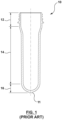
- FIG. 1 depicts an example of a traditional preform 10 which, as stated above, has a closed end, i.e. a base, which is hemispherically shaped. As shown, preform 10 has a neck 12, a body 14 and a base 16 with hemispherically shaped inner and outer faces. Also shown is a gate nub 11 which so to speak is the "foot print" of the injection molding process.
- the wall thickness distribution in the bottle base is not uniform because for the reasons outlined above, unstretched material in amorphous form remains in the gate nub area of the bottle base.
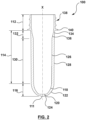
- FIG. 2 depicts a preform 100 implemented according to a non-limiting embodiment of the present invention.
- the preform 100 consists of a neck 112, a base 116 and a body 114 extending between the neck 112 and the base 116.
- the neck 112, the body 114 and the base 116 each have inner and outer faces defining a respective wall thickness therebetween.
- the base 116 has an elliptical inner face 118 with a first flat circular bottom portion 120, and an elliptical outer face 122 with a second flat circular bottom portion 124.
- the first and second flat circular bottom portions 120, 124 each have a center on a vertical center axis X of the preform 100 and a radius R (not shown) of equal size.
- the elliptically shaped inner and outer faces 118, 122 of base 116 provide for a continuous reduction of the wall thickness defined therebetween, and in concert with the first and second flat circular bottom portions 120, 124, they provide in the region of the gate nub 111a defined area of an evenly reduced bottom wall thickness.
- FIG. 2 further shows that the elliptically shaped inner and outer faces 118, 122 extend tangentially from a cylindrically shaped distal end of the inner and outer faces 126, 128 of the body 114, and that the first and second flat circular bottom portions 120, 124 extend tangentially from the elliptically shaped inner and outer faces 118, 122.
- the latter tangency is obtained in that a first ellipse defining the elliptical inner face 118 and a second ellipse defining the elliptical outer face 122 each have a center spaced from a vertical center axis X of the preform 100 by a radius which is equal to the radius R of the first and second flat circular bottom portions 120, 124.
- base 116 has an elongate shape.
- the radius of the first ellipse defining the elliptical inner face 118 of the base 116 has a first radius IR 1 (not shown) which is in parallel with the vertical center axis X of the preform 100, and a second radius IR 2 (not shown) which is perpendicular to the vertical center axis X.
- the first radius IR 1 is such selected that it is greater than both the second radius IR 2 and a radius defining a cylindrical inner face 126 of the body 114, which radius, in the depicted embodiment, defines the cylindrical inner face of a main portion 130 of the body 114 of the preform 100.
- the second ellipse defining the elliptical outer face 122 of the base 116 has a first radius OR 1 (not shown) which is in parallel with the center axis X of the preform 100, and a second radius OR 2 (not shown) which is perpendicular to the center axis X, wherein the first radius OR 1 is such selected that it is greater than both the second radius OR 2 and a radius defining a cylindrical outer face 128 of the body 114, which radius, in the depicted embodiment, defines the cylindrical outer face of the main portion 130 of the body 114 of the preform 100.
- the aforesaid main portion 130 of body 114 has cylindrical inner and outer faces 126, 128 and is associated with a transition portion 132 which extends from the neck 112 and forms a shoulder area in the final bottle.
- the transition portion 132 has a cylindrical outer face 134 having a diameter equal to both a diameter of a cylindrical outer face of the neck 112 and a diameter of the cylindrical outer face 128 of the body main portion 130.
- the inner face 136 of the transition portion has a first part without a draft and a second part that has a conical shape with a continuously decreasing diameter, and a diameter at a distal end of the conical inner face 136 is such selected that the inner face 126 of the body main portion 130 extends tangentially therefrom.
- the outer face of the neck 112 carries a neck finish 138 which in the depicted embodiment is configured to threadably receive a closure cap of the final bottle, and a support ledge 140, i.e. a circular ring, for handling the preform during blow molding and the final bottle during the filling stages.
- a neck finish 138 which in the depicted embodiment is configured to threadably receive a closure cap of the final bottle, and a support ledge 140, i.e. a circular ring, for handling the preform during blow molding and the final bottle during the filling stages.
- the transition portion of the body has an inverse design. Accordingly, the transition portion has a cylindrical inner face with a diameter equal to a diameter of the cylindrical inner face of the body main portion, and a conical outer face with a continuously increasing diameter, wherein the cylindrical outer face of the body main portion extends tangentially from the conical outer face of the transition portion, and the inner and outer faces of the transition portion extend tangentially from cylindrical inner and outer faces of the neck.
- the inner and outer faces of the transition portion each are conical with a continuously decreasing diameter, and extend tangentially from cylindrical inner and outer faces of the neck, and the inner and outer cylindrical faces of the body main portion extend tangentially from the inner and outer faces of the transition portion.
- the inner and outer faces of the body main portion each are conical and taper towards the base, such that a uniform wall thickness of the body main portion is defined therebetween.
- the inner and outer faces of the transition portion each are conical with a continuously decreasing diameter, wherein the conical inner and outer faces of the transition portion extend tangentially from cylindrical inner and outer faces of the neck, and the conical inner and outer faces of the body main portion extend tangentially from the conical inner and outer faces of the transition portion.
- the mold stack comprises a core insert 202, a split mold insert pair 208, a cavity insert 210 and a gate insert 212.
- the core insert 202 comprises a first cavity defining portion 204 including a gate defining portion 206 and, for attachment to a core plate (not shown), an attachment portion 201.
- the first cavity defining portion is configured to define an inner face of the neck and the body of the preform 100
- the gate defining portion 204 is configured to define an inner face of the base thereof.
- the split mold insert pair 208 is configured to define an outer face of the preform neck
- the cavity insert 210 is configured to define an outer face of the body of the preform 100.
- the gate insert 212 is of generally two-part construction having a first portion 211 and a second portion 213.
- the first portion 211 generally lines a region 215 surrounding a nozzle tip (not shown) and, in case of a valve gated nozzle, forms a gate land area 217.
- the second portion 213 forms a second cavity defining portion 214 adjacent the nozzle tip and is configured to define the outer face of the preform base.
- the second portion 213 forms a passage 219 for the flow of a resin into a mold cavity 209 defined, in concert, by the first cavity defining portion of the core insert 202, the split mold insert pair 208, the cavity insert 210 and the second cavity defining portion 214 of the second portion 213 of the gate insert 212.
- the gate defining portion 206 of the first cavity defining portion 204 of core insert 202 has a first elliptical curvature 216 with a first flat circular bottom portion 218, and the second cavity defining portion 214 of the gate insert 212 has a second elliptical curvature 220 with a second flat circular bottom portion 222.
- the first and second flat circular bottom portions 218, 222 each have a center on a vertical center axis X of the mold stack 200, and a radius R (not shown) of equal size. Accordingly - and as shown in FIG.
- first and second elliptical curvatures 216, 220 correspondingly elliptically shaped inner and outer faces of the preform base 114 define a wall thickness therebetween that is continuously reduced.
- first and second elliptical curvatures 216, 220 provide in concert with the first and second flat circular bottom portions 218, 222 that in the region of the preform's gate nub, there is an area - defined by correspondingly shaped first and second flat circular bottom portions of the preform base - of an evenly reduced bottom wall thickness.
- first elliptical curvature 216 of the first cavity defining portion 204 of the core insert 202 is tangent with a distal end thereof and, with reference to FIG. 3 , that the second elliptical curvature of the second cavity defining portion 214 of the gate insert 212 is tangent with a distal end of an inner face of the cavity insert 210 defining the outer face of the preform body. Further, one will appreciate from FIG. 3 that the first and second flat circular bottom portions 218, 222 are tangent with the first and second elliptical curvatures 216, 220.
- a first ellipse defining the first elliptical curvature 216 and a second ellipse defining the second elliptical curvature 220 each have a center spaced from a vertical center axis X of the mold stack 200 by a radius which is equal to the radius R of the first and second flat circular bottom portions 218, 222.
- the preform base defined by the gate defining portion 206 of the first cavity defining portion 204 of the core insert 202 and the second cavity defining portion 214 of the gate insert 212 has an elongate shape as shown in FIG. 3 .
- This elongate shape is obtained in that the first ellipse defining the first elliptical curvature 216 of the gate defining portion 206 has a first radius IR 1 (not shown) which is in parallel with the vertical axis X of the mold stack 200, and a second radius IR 2 (not shown) which is perpendicular to the vertical axis X, with the first radius IR 1 being greater than both the first radius IR 1 and a radius of the first cavity defining portion 204 of the core insert 202 configured to define a cylindrical inner face of the preform body; and in that the second ellipse defining the second elliptical curvature 220 of the second cavity defining portion 214 of the gate insert 212 has a first radius OR 1 (not
- the first cavity defining portion 204 of the core insert 202 configured to define the inner face of the preform neck and the preform body, further comprises a transition portion 224 configured to define a corresponding transition portion of the inner face of the preform body, and a main portion 228 configured to define a corresponding main portion of the inner face of the preform body.
- the transition portion 224 is conical and has a diameter which, in reference to the cylindrical main portion 228, decreases. As one will appreciate from FIGs.
- a proximal end of the transition portion 224 is tangent with the neck defining portion 226 of the first cavity defining portion 204 of the core insert 202, and a distal end of the transition portion 224 is tangent with a proximal end of the main portion 228 of the first cavity defining portion 204.
- the neck defining portion 226 of the first cavity defining portion 204 of the core insert 202 is configured to define a cylindrical inner face of the preform neck
- the split mold insert pair 208 is configured to define a cylindrical outer face of the preform neck as well as a neck finish and a support ledge thereof.
Landscapes
- Engineering & Computer Science (AREA)
- Mechanical Engineering (AREA)
- Manufacturing & Machinery (AREA)
- Physics & Mathematics (AREA)
- Geometry (AREA)
- Blow-Moulding Or Thermoforming Of Plastics Or The Like (AREA)
- Moulds For Moulding Plastics Or The Like (AREA)
- Processing And Handling Of Plastics And Other Materials For Molding In General (AREA)
Description
- The present invention relates to a preform suitable for subsequent stretch blow molding and a mold stack for producing the preform.
- Particularly in the beverage and food industry, containers made of sheet material, glass or ceramics are increasingly being replaced by plastic containers. The user-friendly low weight of plastic containers, in particular plastic bottles, and the environment-friendly use of recyclable plastic materials in the production thereof certainly play a significant role in this substitution.
- The preforms used for producing plastic bottles made, for example, from polyethylene terephthalate (PET), traditionally consist of a hollow cylindrical body, with constant or varying thickness, provided with an open end which already has the final shape of the bottle neck, and with a closed end having a hemispherical shape meant to form the bottom of the bottle.
- In the production of plastic bottles, stretch blow molding, also referred to as biaxial molecular orientation blow molding, is a widely applied process, be it in terms of a two-stage stretch blow molding process or in terms of a single stage blow molding process. In the two-stage process, the preforms are molded in a dedicated injection molding equipment which produces fully cooled preforms. These preforms are packed and fed later into a stretch blow molding machine, where the preforms, in a first step, are heated up to a temperature sufficient for obtaining the requisite softening thereof and then are subjected to stretch blow molding. In the single-stage process, the injection molded preforms are sent directly to a stretch blow molding station integrated in the injection molding equipment.
- When subjected to stretch blow molding, the relatively hot and deformable preform is placed in the metal blow-molding cavity which determines the shape of the final plastic bottle. Through movement of a stretch rod inserted into the preform via its open neck, the preform is stretched as far as the final length of the bottle has been obtained. Then, a pressurized fluid, usually compressed air, is introduced into the stretched preform for causing the preform material to adhere to the walls of the blow-mold cavity.
- It is a matter of fact that regions of the inflating preform that must move and stretch a greater distance in a direction corresponding with the primary, i.e. longitudinal, axis of the bottle cross-sectional shape, will tend to thin more than regions that move in a direction generally corresponding with the secondary, i.e. transversal, axis of the bottle cross-sectional shape. Consequently, the material thickness distribution is not uniform across the bottle's sidewall.
- A well-known technique applied to establish a more uniform material thickness distribution is commonly referred to as "heat profiling". That is, selected regions within the preform stretch are changed by changing the material temperature in those selected regions. As a slightly cooler preform region in the preform body portion will tend to resist and stretch less than in adjacent warmer regions, aligning the cooler preform regions with corresponding areas of the bottle which tend to have an otherwise relatively thinner wall thickness, will consequently stretch less, thereby improving material thickness distribution uniformity.
- As it will be appreciated by those skilled in the art, heat profiling provides an effective tool for improving material thickness distribution uniformity within a preform's sidewall. With respect to the hemispherically shaped closed end employed in the traditional preform design, this tool, however, fails to improve the material thickness distribution uniformity of this region. This is as the hemispherically shaped closed end inherently is associated with a low surface to volume ratio, which ratio renders it virtually impossible to effectively heat profile sub-regions within the closed end. Thus, heat profiling does not work to prevent that unstretched amorphous material remains in the bottle base, in particular in the region around its gate nub.
-
US Patent Application No. 2014/0030461 A1 (BUNEL et al.; PUBLISHED 30th January 2014 ) teaches an improvement to the bottom of preforms made of a thermoplastic material and used for the production of stretch blown molded bottles. The proposed arrangement provides a transition area in the bottom of the stretch blown molded bottle which transition area is said to be less prone to the phenomenon of fissuring between the central portion of the bottle bottom and the periphery thereof where the material is biaxially expanded. -
GB 2 048 757 A (OTA et al., PUBLISHED 17th December 1980 -
US Patent No. US 7 128 865 B2 (MARTIN; PUBLISHED ) teaches an injection molding method and apparatus for ejecting a molded plastic preform from a mold. A first lifting structure and/or step is configured to have an inner surface with an area for sealing and aligning with a complementary surface on a core, and to have an upper surface with an area for sealing and aligning with a complementary surface on a second lifting structure, said upper surface of said first lifting structure being configured to lift a molded plastic preform from the injection mold in a lifting direction for a first period of time, the lower portion of the molded plastic preform lying in a plane substantially perpendicular to the lifting direction. A second lifting structure and/or step is configured to have an inner surface configured to lift an outer surface of the molded plastic preform from the injection mold in the lifting direction for a second period of time, the outer surface of the molded plastic preform including structure lying in a plane substantially parallel with the lifting direction. Since the molded plastic preform is lifted by its end, the preform does not have to be solidified at its interior, thus allowing earlier removal of the preform from the mold, reducing cycle time.31th 10 2006 - In broad terms, the said bottom arrangement of a preform with a cylindrical body and a neck can be described as follows. In reference to an external central point OP located on the vertical center axis of the preform, the external contour of the preform bottom is provided by a spherical cap and a tapered surface, which surface, in reference to a point NP defining the junction between the external contour of the preform body and the one of the preform bottom, extends towards the spherical cap and is connected therewith via a toroidal ring having a surface that is tangent to both the spherical cap and the tapered surface. In reference to an internal point S located on the vertical center axis of the preform, the internal contour of the preform bottom is provided by a central rounded portion having the shape of a spherical dome, and a spherical surface, which surface, in reference to a point T located at the end of the envelope of the cylindrical cavity of the preform body, extends towards the spherical dome and is connected therewith via a toroidal annular surface created by an arc of a circle with a radius R.
- Those skilled in the art will appreciate that this arrangement of the preform bottom is still not satisfactory. Albeit the tapered surface of the bottom's outer contour helps that the material in this region stretches out more effectively, due to the configuration of the internal and external contours of the preform bottom around the gate nub, unstretched and amorphous material inevitably will remain in the bottom of the stretch blown bottle, in particular in the region around its gate nub.
- The object underlying the present invention is to provide a preform suitable for subsequent stretch blow molding and mitigating the drawbacks associated with traditional preforms having a hemispherically shaped closed end.
- This object is solved by a preform having the features defined by claim 1 and a mold stack having the features of claim 9.
- According to the present invention, the closed end of the preform, i.e. the base thereof, has an elliptical inner face with a first flat circular bottom portion, and an elliptical outer face with a second flat circular bottom portion, wherein the first and second flat circular bottom portions each have a center on a vertical center axis of the preform and a radius R of equal size.
- The elliptically shaped inner and outer faces of the base provide for a continuous reduction of a wall thickness defined therebetween and, in concert with the flat circular bottom portions, they provide a defined area of an evenly reduced bottom wall thickness in the region of the gate nub. The material reduction in the regions of the base which in the inflated preform move in a direction generally corresponding with the transversal axis of the bottle cross-sectional shape, thus provides that these regions effectively stretch out and thin accordingly. Further, otherwise unstretched material locked in amorphous form in the region around the gate nub of the stretch blown bottle, is made available for distribution in the body and shoulder area of the bottle, thereby improving bottle performance while providing a bottle advantageously having a lower base weight. Yet further, the elliptically shaped inner and outer faces together with the respective flat circular bottom portions provide an increase of the surface to volume ratio of the base, thereby making effective heat profiling of the base possible.
- Preferably, the elliptical inner and outer faces of the base each extend tangentially from a respective distal end of the inner and outer faces of the preform body. Further, a first ellipse defining the elliptical inner face and a second ellipse defining the elliptical outer face each have a center spaced from the vertical center axis of the preform by a radius which is equal to the radius R of the first and second flat circular bottom portions. Accordingly, the first flat circular bottom portion extends tangentially from the elliptical inner face and the second flat circular bottom portion extends tangentially from the elliptical outer face.
- The tangencies at the intersections of the distal end of the inner and outer faces of the preform body and the inner and outer elliptical faces of the base advantageously support the flow of the melt during the injection molding process as well as for subsequent stretch blow-molding. By way of the elliptical inner and outer faces of the base, the wall thickness defined therebetween is continuously reduced. Thus, the tangencies at the intersections of the elliptical inner and outer faces and the first and second flat circular bottom sections provide that the bottom wall thickness defined between the first and second flat circular bottom portions is equal to the smallest wall thickness resulting from the continuous wall thickness reduction through the elliptical inner and outer faces. Accordingly, material in the gate nub area will more readily stretch out and thin accordingly.
- Preferably, the first ellipse defining the elliptical inner face has a first radius IR1 which is in parallel with the vertical center axis of the perform and a second a second radius IR2 which is perpendicular to said vertical center axis, wherein the first radius IR1 is greater than both the second radius IR2 and a radius of a cylindrical inner face of the preform body. Similarly, the second ellipse defining the elliptical outer face has a first radius OR1 which is in parallel with the vertical center axis of the preform and a second radius OR2 which is perpendicular to the vertical center axis, wherein the first radius OR1 is greater than both the second radius OR2 and a radius of a cylindrical outer face of the preform body. The such configured preform base has an elongate shape and thus provides for a surface to volume ratio, which is of advantage for effectively heat profiling the preform base.
- Preferably, the radius R of the first and second flat circular bottom portions is equal to 0.4 times of the radius of the cylindrical outer face of the preform body.
- In an embodiment of a preform having a base in accordance with the present invention, the preform body consists of a body main portion and a transition portion which extends from the preform neck and forms a shoulder area in the final bottle. Preferably, the transition portion has a cylindrical outer face having a diameter equal to a diameter of both a cylindrical outer face of the neck and a cylindrical outer face of the body main portion, and a conical inner face with decreasing diameter. Preferably, the conical inner face of the transition portion extends tangentially from a cylindrical inner face of the neck, and the cylindrical inner face of the body main portion extends tangentially from the conical inner face of the transition portion.
- Since the open end of a preform of the species in question already has the final shape of the bottle neck, the outer face of the neck, preferably, carries a neck finish configured to receive a closure of the bottle, and a support ledge, i.e. a circular ring for handling the preform during blow molding and the final bottle during the filling stages.
- The mold stack featured according to a non-limiting embodiment of the present invention for injection molding a preform suitable for subsequent stretch blow molding comprises a core insert, a split mold insert, a cavity insert and a gate insert, which in concert define a mold cavity. The core insert comprises a first cavity defining portion configured to define an inner face of a neck and a body of the preform, and, via a gate defining portion thereof, an inner face of a base of the preform. The split mold insert is configured to define an outer face of the preform neck, the cavity insert is configured to define an outer face of the preform body, and the gate insert comprising a second cavity defining portion is configured to define an outer face of the preform base.
- According to the present invention, the gate defining portion of the first cavity defining portion of the core insert has a first elliptical curvature with a first flat circular bottom portion, and the second cavity defining portion of the gate insert has a second elliptical curvature with a second flat circular bottom portion, wherein said first and second flat circular bottom portions each have a center on a vertical center axis of the mold stack and a radius R of equal size. Accordingly, the injection molded preform has a base having an elliptical inner face with a first flat circular bottom portion, an elliptical outer face with a second flat circular bottom portion, and the first and second flat circular bottom portions each have a center on a vertical center axis of the preform and a radius of equal size. The, elliptically shaped inner and outer faces of the base of the injection molded preform thus provide for a continuous reduction of material in that region and, in concert with the first and second flat circular bottom portions, in a region of the gate nub area, they provide a defined area of an evenly reduced wall thickness. The material reduction in the regions of the preform base which in the inflated preform move in a direction generally corresponding with the transversal axis of the bottle cross-sectional shape, provides that these regions will stretch out effectively and thin accordingly. Further, otherwise unstretched material locked in amorphous form in the region around the gate nub of the stretch blown bottle is made available for distribution in the body and the shoulder area of the bottle, thereby improving bottle performance, while providing a bottle advantageously having a lower base weight. Yet further, the elliptically shaped inner and outer faces of the preform base together with the respective first and second flat circular bottom portions provide an increase of the surface to volume ratio of the preform base, thereby making an effective heat profiling of the preform's base possible.
- Preferably, the first elliptical curvature of the gate defining portion of the core insert is tangent with a distal end of the first cavity defining portion of the core insert, and the second elliptical curvature of the second cavity defining portion of the gate insert is tangent with a distal end of an inner surface of the cavity insert defining the outer face of the preform body. Further, a first ellipse defining the first elliptical curvature and a second ellipse defining the second elliptical curvature each have a center spaced from the vertical center axis of the mold stack by a radius equal to the radius R of the first and second flat circular bottom portions. Accordingly, the first flat circular bottom portion is tangent with the first elliptical curvature and the second flat circular bottom portion is tangent with the second elliptical curvature.
- The tangency at the intersection of the first elliptical curvature and a distal end of the first cavity defining portion of the core insert and the tangency at the intersection of the second elliptical curvature and the distal end of an inner surface of the cavity insert defining the outer face of the preform body, advantageously support the flow of the melt in the mold cavity during the injection molding process as well as for subsequent stretch blow-molding. Further, the elliptical first and second curvatures provide that the wall thickness of the preform's base defined accordingly is continuously reduced. Thus, the tangencies at the intersections at the first and second elliptical curvatures and the first and second flat circular bottom sections provide that the preform's wall thickness defined by the first and second bottom portions is equal to a smallest wall thickness of the preform base resulting from the continuously reduced wall thickness provided by the first and second elliptical curvatures. Accordingly, it is provided that material in the preform's gate nub area effectively can stretch out and thin accordingly.
- Preferably, the first ellipse defining the first elliptical curvature has a first radius IR1 which is in parallel with the vertical center axis of the mold stack and a second radius IR2 which is perpendicular to the vertical center axis of the mold stack, wherein the first radius IR1 is greater than both the second radius IR2 and a radius of the first cavity defining portion of the core insert defining at least in part a cylindrical inner face of the preform body. Similarly, the second ellipse defining the second elliptical curvature has a first radius OR1 which is parallel to the vertical center axis of the mold stack and a second radius OR2 which is perpendicular to the vertical center axis of the mold stack, wherein the first radius OR1 is greater than both the second radius OR2 and a radius of the inner surface of the cavity insert defining a cylindrical outer face of the preform body.
- Configuring the first elliptical curvature of the gate defining portion of the core insert and the second elliptical curvature of the second cavity defining portion of the gate insert in such a way, provides that the preform base will be more elongate in shape, which elongate shape is in particular of advantage for effectively heat profiling the preform base.
- Preferably, the radius R of the first and second flat circular bottom portions provided by the gate defining portion of the first cavity defining portion of the core insert and the second cavity defining potion of the gate insert, respectively, is equal to 0.4 times of a radius R of the cavity insert defining the cylindrical outer face of the preform body.
- In an embodiment of the mold stack of the present invention, the first cavity defining portion of the core insert defining the inner face of the preform neck and the preform body further comprises a transition portion which is tangent with a neck defining portion of the first cavity defining portion of the core insert, and a main portion which is tangent with the transition portion. Preferably, the transition portion is configured to define a conical inner face with decreasing diameter of a transition portion of the preform body, and the main portion is configured to define a cylindrical inner face of a main body portion of the preform body.
- Preferably, the neck defining portion of the first cavity defining portion of the core insert is configured to define a cylindrical inner face of the preform neck, and the split mold insert pair is configured to define a cylindrical outer face with a neck finish and a support ledge of the preform neck.
- The non-limiting embodiments of the present invention will be more fully appreciated by reference to the accompanying drawings, in which:
-
FIG. 1 depicts a cross-section view of an example of atraditional preform 10 having a hemispherically shaped base; -
FIG. 2 depicts a cross-section view of an embodiment of apreform 100 having a base implement according to the present invention; -
FIG. 3 depicts a cross-section view of amold stack 200 configured to produce thepreform 100 ofFIG. 2 ; -
FIG. 4 depicts a side view of acore insert 202 of the mold stack ofFIG. 3 ; -
FIG. 5 depicts a cross-section view of agate insert 212 of the mold stack ofFIG. 3 . - The drawings serve the purpose of illustration and are not to scale.
- Reference will now be made to embodiments of a preform implement according to the present invention and a mold stack for producing the same. The invention is set out in the appended set of claims.
- Further, it will be recognized by those skilled in the art that certain structural and/or operational details of the non-limiting embodiments discussed hereinafter may be modified or amended.
FIG. 1 depicts an example of atraditional preform 10 which, as stated above, has a closed end, i.e. a base, which is hemispherically shaped. As shown, preform 10 has aneck 12, abody 14 and a base 16 with hemispherically shaped inner and outer faces. Also shown is agate nub 11 which so to speak is the "foot print" of the injection molding process. - In the final bottle produced from such a traditional preform, the wall thickness distribution in the bottle base is not uniform because for the reasons outlined above, unstretched material in amorphous form remains in the gate nub area of the bottle base.
-
FIG. 2 depicts apreform 100 implemented according to a non-limiting embodiment of the present invention. Thepreform 100 consists of aneck 112, abase 116 and abody 114 extending between theneck 112 and thebase 116. Theneck 112, thebody 114 and the base 116 each have inner and outer faces defining a respective wall thickness therebetween. - As shown, the
base 116 has an ellipticalinner face 118 with a first flat circularbottom portion 120, and an ellipticalouter face 122 with a second flat circularbottom portion 124. The first and second flat circularbottom portions preform 100 and a radius R (not shown) of equal size. As it is apparent fromFIG. 2 , the elliptically shaped inner andouter faces base 116 provide for a continuous reduction of the wall thickness defined therebetween, and in concert with the first and second flat circularbottom portions -
FIG. 2 further shows that the elliptically shaped inner andouter faces outer faces body 114, and that the first and second flat circularbottom portions outer faces inner face 118 and a second ellipse defining the ellipticalouter face 122 each have a center spaced from a vertical center axis X of thepreform 100 by a radius which is equal to the radius R of the first and second flat circularbottom portions - From
FIG. 2 one will further appreciate thatbase 116 has an elongate shape. In order to obtain such a configuration of the base, the radius of the first ellipse defining the ellipticalinner face 118 of thebase 116 has a first radius IR1 (not shown) which is in parallel with the vertical center axis X of thepreform 100, and a second radius IR2 (not shown) which is perpendicular to the vertical center axis X. The first radius IR1 is such selected that it is greater than both the second radius IR2 and a radius defining a cylindricalinner face 126 of thebody 114, which radius, in the depicted embodiment, defines the cylindrical inner face of amain portion 130 of thebody 114 of thepreform 100. Similarly, the second ellipse defining the ellipticalouter face 122 of thebase 116 has a first radius OR1 (not shown) which is in parallel with the center axis X of thepreform 100, and a second radius OR2 (not shown) which is perpendicular to the center axis X, wherein the first radius OR1 is such selected that it is greater than both the second radius OR2 and a radius defining a cylindricalouter face 128 of thebody 114, which radius, in the depicted embodiment, defines the cylindrical outer face of themain portion 130 of thebody 114 of thepreform 100. - In the embodiment depicted in
FIG. 2 , the aforesaidmain portion 130 ofbody 114 has cylindrical inner andouter faces transition portion 132 which extends from theneck 112 and forms a shoulder area in the final bottle. As shown, thetransition portion 132 has a cylindricalouter face 134 having a diameter equal to both a diameter of a cylindrical outer face of theneck 112 and a diameter of the cylindricalouter face 128 of the bodymain portion 130. Theinner face 136 of the transition portion has a first part without a draft and a second part that has a conical shape with a continuously decreasing diameter, and a diameter at a distal end of the conicalinner face 136 is such selected that theinner face 126 of the bodymain portion 130 extends tangentially therefrom. - The outer face of the
neck 112 carries aneck finish 138 which in the depicted embodiment is configured to threadably receive a closure cap of the final bottle, and asupport ledge 140, i.e. a circular ring, for handling the preform during blow molding and the final bottle during the filling stages. - In an alternative embodiment (not shown), the transition portion of the body has an inverse design. Accordingly, the transition portion has a cylindrical inner face with a diameter equal to a diameter of the cylindrical inner face of the body main portion, and a conical outer face with a continuously increasing diameter, wherein the cylindrical outer face of the body main portion extends tangentially from the conical outer face of the transition portion, and the inner and outer faces of the transition portion extend tangentially from cylindrical inner and outer faces of the neck.
- In a further alternative embodiment (not shown), the inner and outer faces of the transition portion each are conical with a continuously decreasing diameter, and extend tangentially from cylindrical inner and outer faces of the neck, and the inner and outer cylindrical faces of the body main portion extend tangentially from the inner and outer faces of the transition portion.
- In a yet further embodiment (not shown), the inner and outer faces of the body main portion each are conical and taper towards the base, such that a uniform wall thickness of the body main portion is defined therebetween. The inner and outer faces of the transition portion each are conical with a continuously decreasing diameter, wherein the conical inner and outer faces of the transition portion extend tangentially from cylindrical inner and outer faces of the neck, and the conical inner and outer faces of the body main portion extend tangentially from the conical inner and outer faces of the transition portion.
- With reference to
FIG. 3 , there is depicted amold stack 200 configured to produce thepreform 100 shown inFIG. 2 . The mold stack comprises acore insert 202, a splitmold insert pair 208, acavity insert 210 and agate insert 212. - With continued reference to
FIG. 3 and with reference toFIG. 4 , thecore insert 202 comprises a firstcavity defining portion 204 including agate defining portion 206 and, for attachment to a core plate (not shown), anattachment portion 201. The first cavity defining portion is configured to define an inner face of the neck and the body of thepreform 100, and thegate defining portion 204 is configured to define an inner face of the base thereof. - As shown in
FIG. 3 , the splitmold insert pair 208 is configured to define an outer face of the preform neck, and thecavity insert 210 is configured to define an outer face of the body of thepreform 100. - With continued reference to
FIG. 3 and with reference toFIG. 5 , thegate insert 212 is of generally two-part construction having afirst portion 211 and asecond portion 213. Thefirst portion 211 generally lines aregion 215 surrounding a nozzle tip (not shown) and, in case of a valve gated nozzle, forms agate land area 217. Thesecond portion 213 forms a secondcavity defining portion 214 adjacent the nozzle tip and is configured to define the outer face of the preform base. Further, thesecond portion 213 forms apassage 219 for the flow of a resin into amold cavity 209 defined, in concert, by the first cavity defining portion of thecore insert 202, the splitmold insert pair 208, thecavity insert 210 and the secondcavity defining portion 214 of thesecond portion 213 of thegate insert 212. - As shown in
FIGs. 3 ,4 and5 , thegate defining portion 206 of the firstcavity defining portion 204 ofcore insert 202 has a firstelliptical curvature 216 with a first flat circularbottom portion 218, and the secondcavity defining portion 214 of thegate insert 212 has a secondelliptical curvature 220 with a second flat circularbottom portion 222. The first and second flat circularbottom portions mold stack 200, and a radius R (not shown) of equal size. Accordingly - and as shown inFIG. 3 -, it is provided that by way of the first and secondelliptical curvatures preform base 114 define a wall thickness therebetween that is continuously reduced. Further, the first and secondelliptical curvatures bottom portions - From
FIGs. 3 and4 one will appreciate that the firstelliptical curvature 216 of the firstcavity defining portion 204 of thecore insert 202 is tangent with a distal end thereof and, with reference toFIG. 3 , that the second elliptical curvature of the secondcavity defining portion 214 of thegate insert 212 is tangent with a distal end of an inner face of thecavity insert 210 defining the outer face of the preform body. Further, one will appreciate fromFIG. 3 that the first and second flat circularbottom portions elliptical curvatures elliptical curvature 216 and a second ellipse defining the secondelliptical curvature 220 each have a center spaced from a vertical center axis X of themold stack 200 by a radius which is equal to the radius R of the first and second flat circularbottom portions - The preform base defined by the
gate defining portion 206 of the firstcavity defining portion 204 of thecore insert 202 and the secondcavity defining portion 214 of thegate insert 212, has an elongate shape as shown inFIG. 3 . This elongate shape is obtained in that the first ellipse defining the firstelliptical curvature 216 of thegate defining portion 206 has a first radius IR1 (not shown) which is in parallel with the vertical axis X of themold stack 200, and a second radius IR2 (not shown) which is perpendicular to the vertical axis X, with the first radius IR1 being greater than both the first radius IR1 and a radius of the firstcavity defining portion 204 of thecore insert 202 configured to define a cylindrical inner face of the preform body; and in that the second ellipse defining the secondelliptical curvature 220 of the secondcavity defining portion 214 of thegate insert 212 has a first radius OR1 (not shown) which is in parallel with the vertical center axis of themold stack 200, and a second radius OR2 (not shown) which is perpendicular to the vertical center axis X of themold stack 200, with the first radius OR1 being greater than both the second radius OR2 and a radius of an inner surface of thecavity insert 210 configured to define a cylindrical outer face of the preform body. - In the embodiment of the
mold stack 200 depicted inFIG. 3 , the firstcavity defining portion 204 of thecore insert 202 configured to define the inner face of the preform neck and the preform body, further comprises atransition portion 224 configured to define a corresponding transition portion of the inner face of the preform body, and amain portion 228 configured to define a corresponding main portion of the inner face of the preform body. In the embodiment shown, thetransition portion 224, is conical and has a diameter which, in reference to the cylindricalmain portion 228, decreases. As one will appreciate fromFIGs. 3 and4 , a proximal end of thetransition portion 224 is tangent with theneck defining portion 226 of the firstcavity defining portion 204 of thecore insert 202, and a distal end of thetransition portion 224 is tangent with a proximal end of themain portion 228 of the firstcavity defining portion 204. - In the shown embodiment, the
neck defining portion 226 of the firstcavity defining portion 204 of thecore insert 202 is configured to define a cylindrical inner face of the preform neck, and the splitmold insert pair 208 is configured to define a cylindrical outer face of the preform neck as well as a neck finish and a support ledge thereof. - It is noted that the foregoing has outlined some of more pertinent non-limiting embodiments. The described non-limiting embodiments ought to be considered to be merely illustrative of some of the mere prominent features and applications.
Claims (15)
- A preform (100) suitable for subsequent blow molding, the preform (100) comprising:a neck (112), a base (116) and a body (114) extending therebetween, the neck (112), the body (114) and the base (116) each having inner and outer faces defining a wall thickness therebetween, characterized in thatthe base (116) having an elliptical inner face (118) with a first flat circular bottom portion (120), and an elliptical outer face (122) with a second flat circular bottom portion (124), andthe first and second flat circular bottom portions (120, 124) each having a center on a vertical center axis (X) of the preform (100) and a radius R of equal size.
- The preform (100) according to claim 1, whereinthe elliptical inner face (118) of the base (116) extends tangentially from a distal end of an inner face (126) of the body (114), and the elliptical outer face (122) of the base extends tangentially from a distal end of an outer face (128) of the body (114), anda first ellipse defining the elliptical inner face (118) and a second ellipse defining the elliptical outer face (122) each have a center spaced from the vertical center axis (X) of the preform (100) by a radius equal to the radius R of the first and second flat circular bottom portions (120, 124).
- The preform (100) according to claim 2, whereinthe first ellipse defining the elliptical inner face (118) has a first radius IR1 being parallel to the vertical center axis (X) of the preform (100) and a second radius IR2 being perpendicular to the vertical center axis (X) of the preform (100), the first radius IR1 being greater than both the second radius IR2 and a radius of a cylindrical inner face (126) of the body (114), andthe second ellipse defining the elliptical outer face (122) has a first radius OR1 being parallel to the vertical center axis (X) of the preform (100) and a second radius OR2 being perpendicular to the vertical axis (X) of the preform (100), the first radius OR1 being greater than both the second radius OR2 and a radius of a cylindrical outer face (128) of the body (114).
- The preform (100) according to claim 3, wherein
the radius R of the first and second flat circular bottom portions (120, 124) is equal to 0.4 times of the radius of the cylindrical outer face (128) of the body (114). - The preform (100) according to one of claims 1 to 4, wherein the body (114) consists of a body main portion (130), and a transition portion (132) extending from the neck (112).
- The preform (100) according to claim 5, whereinthe transition portion (132) has a cylindrical outer face (134) with a diameter equal to a diameter of a cylindrical outer face (128) of the body main portion (130), and a conical inner face (136) with a continuously decreasing diameter, and whereinthe inner face (126) of the body main portion (130) extends tangentially from the conical inner face (136) of the transition portion (132).
- The preform (100) according to claim 5 or 6, whereinthe neck (112) has cylindrical inner and outer faces, andthe outer and inner faces (134, 136) of the transition portion (132) extend tangentially from the outer and inner faces of the neck (112).
- The preform (100) according to one of claims 1 to 7, wherein
the neck (112) on its outer face carries a neck finish (138) and a support ledge (140). - A mold stack (200) for injection molding a preform having a neck, a body and a base, the mold stack (200) comprising:a core insert (202) comprising a first cavity defining portion (204) configured to define an inner face of the neck and the body of the preform and, via a gate defining portion (206) thereof, an inner face of the base of the preform,a split mold insert pair (208) configured to define an outer face of the neck of the preform,a cavity insert (210) configured to define an outer face of the body of the preform, anda gate insert (212) comprising a second cavity defining portion (214) configured to define an outer face of the base of the preform; characterized in thatthe gate defining portion (206) of the first cavity defining portion (204) of the core insert (202) having a first elliptical curvature (216) with a first flat circular bottom portion (218), and the second cavity defining portion (214) of the gate insert (212) having a second elliptical curvature (220) with a second flat circular bottom portion (222), andthe first and second flat circular bottom portions (218, 222) each having a center on a vertical center axis (X) of the mold stack (200) and a radius R of equal size.
- The mold stack (200) according to claim 9, whereinthe first elliptical curvature (216) of the gate defining portion (206) of the core insert (202) is tangent with a distal end of the first cavity defining portion (204) of the core insert (202), and the second elliptical curvature (220) of the second cavity defining portion (214) is tangent with a distal end of an inner surface of the cavity insert (210) defining the outer face of the body of the preform, and whereina first ellipse defining the first elliptical curvature (216) and a second ellipse defining the second elliptical curvature (220) each have a center spaced from the vertical center axis (X) of the mold stack (200) by a radius equal to the radius R of the first and second flat circular bottom portions (218, 222).
- The mold stack according to claim 10, whereinthe first ellipse defining the first elliptical curvature (216) has a first radius IR1 being parallel to the vertical center axis (X) of the mold stack (200) and a second radius IR2 being perpendicular to the vertical center axis (X) of the mold stack (200), the first radius IR1 being greater than both the second radius IR2 and a radius of the first cavity defining portion (204) of the core insert (202) defining at least in part a cylindrical inner face of the body of the preform, andthe second ellipse defining the second elliptical curvature (220) has a first radius OR1 being parallel to the vertical center axis (X) of the mold stack (200) and a second radius OR2 being perpendicular to the vertical center axis (X) of the mold stack (200), the first radius OR1 being greater than both the second radius OR2 and a radius of an inner surface of the cavity insert (210) defining a cylindrical outer face of the body of the preform.
- The mold stack (200) according to claim 11, wherein
the radius R of the first and second flat circular bottom portions (218, 222) is equal to 0.4 times of the radius of the cavity insert (210) defining the cylindrical outer face of the body of the perform. - The mold stack (200) according to one of claims 9 to 12, wherein
the first cavity defining portion (204) of the core insert (202) defining the inner face of the neck and the body of the preform, further comprises a transition portion (224) being tangent with a neck defining portion (226) of the first cavity defining portion (204), and a main portion (228) being tangent with the transition portion (224) of the first cavity defining portion (204). - The mold stack (200) according to claim 13, whereinthe transition portion (224) is conical in shape and configured to define a conical inner face with decreasing diameter of a transition portion of the body of the preform, andthe main portion (228) is configured to define a cylindrical inner face of a main body portion of the body of the preform.
- The mold stack (200) according to one of claims 9 to 14, whereinthe split mold insert pair (208) in configured to define a cylindrical outer face with a neck finish and a support ledge of the preform neck, anda neck defining portion (226) of the first cavity defining portion (204) of the core insert (202) is configured to define a cylindrical inner face of the preform neck.
Applications Claiming Priority (2)
| Application Number | Priority Date | Filing Date | Title |
|---|---|---|---|
| US201862693491P | 2018-07-03 | 2018-07-03 | |
| PCT/CA2019/050842 WO2020006624A1 (en) | 2018-07-03 | 2019-06-14 | A preform and mold stack |
Publications (3)
| Publication Number | Publication Date |
|---|---|
| EP3817907A1 EP3817907A1 (en) | 2021-05-12 |
| EP3817907A4 EP3817907A4 (en) | 2022-04-27 |
| EP3817907B1 true EP3817907B1 (en) | 2024-08-21 |
Family
ID=69060515
Family Applications (1)
| Application Number | Title | Priority Date | Filing Date |
|---|---|---|---|
| EP19830328.1A Active EP3817907B1 (en) | 2018-07-03 | 2019-06-14 | A preform and mold stack |
Country Status (4)
| Country | Link |
|---|---|
| US (1) | US11865742B2 (en) |
| EP (1) | EP3817907B1 (en) |
| CN (1) | CN112313062B (en) |
| WO (1) | WO2020006624A1 (en) |
Citations (1)
| Publication number | Priority date | Publication date | Assignee | Title |
|---|---|---|---|---|
| EP2263843B1 (en) * | 2009-06-19 | 2012-07-18 | A.K. Technical Laboratory, Inc., | Preform for stretch blow-molded bottle |
Family Cites Families (26)
| Publication number | Priority date | Publication date | Assignee | Title |
|---|---|---|---|---|
| JPS55146718A (en) | 1979-05-01 | 1980-11-15 | Yoshino Kogyosho Co Ltd | Intermediate blank made of synthetic resin for molding biaxially spread bottle |
| JPH0694158B2 (en) | 1990-10-26 | 1994-11-24 | 日精エー・エス・ビー機械株式会社 | Preform for molding a can body made of synthetic resin and method for manufacturing a can body made of synthetic resin using the same |
| US5498152A (en) | 1994-05-02 | 1996-03-12 | Husky Injection Molding Systems Ltd. | Preform orientation apparatus |
| CN1239490A (en) * | 1997-07-04 | 1999-12-22 | 三菱树脂株式会社 | Polyester resin compsn. and bottle produced from resin compsn. |
| US6649121B1 (en) | 1999-10-08 | 2003-11-18 | Taisei Kako Co., Ltd. | Method of producing laminated bottles having peelable inner layer |
| JP4687855B2 (en) * | 2001-06-29 | 2011-05-25 | 株式会社青木固研究所 | Preform for small flat container and small flat container |
| JP2003104404A (en) * | 2001-09-28 | 2003-04-09 | Aoki Technical Laboratory Inc | Resin tubular container and preform thereof |
| DE10215722B4 (en) * | 2002-04-10 | 2009-11-26 | Husky Injection Molding Systems Ltd., Bolton | Method and device for processing preforms |
| US7128865B2 (en) | 2003-12-17 | 2006-10-31 | Husky Injection Molding Systems Ltd. | Apparatus and method for two stage ejection of a molded preform from a mold |
| JP4714509B2 (en) | 2005-06-13 | 2011-06-29 | 株式会社青木固研究所 | Injection stretch blow molding method |
| ITMO20050315A1 (en) | 2005-11-25 | 2007-05-26 | Sacmi Cooperativa Maccanici Imola Scrl | PREFORM TO OBTAIN CONTAINERS |
| US8020717B2 (en) | 2007-04-19 | 2011-09-20 | Graham Packaging Company, Lp | Preform base and method of making a delamination and crack resistant multilayer container base |
| JP5033469B2 (en) | 2007-05-08 | 2012-09-26 | 株式会社青木固研究所 | Injection stretch blow molding method for heat-resistant bottles |
| US7628605B2 (en) | 2007-07-20 | 2009-12-08 | Husky Injection Molding Systems Ltd. | Mold stack |
| BE1018460A5 (en) * | 2008-02-12 | 2010-12-07 | Resilux | COLOR FORM AND METHOD FOR MANUFACTURING A POLYCHROMATIC PLASTIC CONTAINER. |
| NL2003132C2 (en) * | 2009-07-03 | 2011-01-04 | Heineken Supply Chain Bv | Container, preform assembly and method and apparatus for forming containers. |
| MX340202B (en) | 2010-12-09 | 2016-06-30 | Husky Injection Molding Systems Ltd | PREFORM AND PILE OF MOLDS TO PRODUCE THE PREFORM. |
| FR2974070B1 (en) | 2011-04-13 | 2013-05-17 | Sidel Participations | IMPROVEMENT IN THE BACKGROUND OF PREFORMS |
| DE102012004613A1 (en) | 2012-02-24 | 2013-07-11 | Mahir Aktas | Method and device for producing an optimized bottom contour of preforms |
| CH706889A2 (en) * | 2012-09-10 | 2014-03-14 | Alpla Werke | Preform for producing plastic containers in a stretch blow molding. |
| ITMI20130115A1 (en) | 2013-01-25 | 2014-07-26 | Concordia Dev Srl | PREFORMATION OF PLASTIC MATERIALS WITH A LOW END CLOSED END |
| DE102013011315A1 (en) | 2013-07-01 | 2015-01-08 | Mahir Aktas | Apparatus for the production of preforms and for the blow molding of containers |
| CN204249143U (en) * | 2014-03-21 | 2015-04-08 | 赫斯基注塑系统有限公司 | container preform |
| DE102014112438A1 (en) | 2014-08-29 | 2016-03-03 | Mht Mold & Hotrunner Technology Ag | System for the further treatment of preforms produced by injection molding |
| CA2968124C (en) * | 2014-12-15 | 2020-03-10 | Husky Injection Molding Systems Ltd. | Method for converting a design of an original preform and a related mold stack for the molding thereof |
| JP6032320B2 (en) * | 2015-03-25 | 2016-11-24 | 東洋製罐株式会社 | PREFORM, PREFORM MOLD, AND METHOD FOR PRODUCING SYNTHETIC RESIN CONTAINER |
-
2019
- 2019-06-14 EP EP19830328.1A patent/EP3817907B1/en active Active
- 2019-06-14 CN CN201980041125.XA patent/CN112313062B/en active Active
- 2019-06-14 WO PCT/CA2019/050842 patent/WO2020006624A1/en not_active Ceased
- 2019-06-14 US US17/059,035 patent/US11865742B2/en active Active
Patent Citations (1)
| Publication number | Priority date | Publication date | Assignee | Title |
|---|---|---|---|---|
| EP2263843B1 (en) * | 2009-06-19 | 2012-07-18 | A.K. Technical Laboratory, Inc., | Preform for stretch blow-molded bottle |
Also Published As
| Publication number | Publication date |
|---|---|
| CN112313062B (en) | 2022-10-11 |
| EP3817907A1 (en) | 2021-05-12 |
| US11865742B2 (en) | 2024-01-09 |
| CN112313062A (en) | 2021-02-02 |
| WO2020006624A1 (en) | 2020-01-09 |
| US20210213659A1 (en) | 2021-07-15 |
| CA3101358A1 (en) | 2020-01-09 |
| EP3817907A4 (en) | 2022-04-27 |
Similar Documents
| Publication | Publication Date | Title |
|---|---|---|
| US11161293B2 (en) | Blow nozzle with holes for directional blowing | |
| US4439393A (en) | Method of producing synthetic resin bottle with handle | |
| US4629598A (en) | Method for forming plastic bottle with integral handle | |
| US4785948A (en) | Blow molded plastic container having a reinforced wall structure and preform therefor | |
| JP2000506078A (en) | Improvement of thermoplastic parison and related manufacturing method | |
| CN101522385B (en) | Improved plastic preform | |
| JPH0622859B2 (en) | Container and intermediate products produced by stretch blow molding | |
| CN102933465B (en) | Container including an arched bottom having a square seat | |
| US4432530A (en) | Mold-core rod combination for forming an injection molded plastic parison | |
| US20060051541A1 (en) | Polymeric preform for a blow molded plastic article | |
| US9694531B2 (en) | Preforms for blow moulding | |
| CN106794599A (en) | Thickness is around the transformable preform of main shaft | |
| CA3101358C (en) | A preform and mold stack | |
| US11865742B2 (en) | Preform and mold stack | |
| EP2633977B1 (en) | Production method for hollow container | |
| CN104955623B (en) | The preform of the plastic material of blind end with mitigation | |
| US4588620A (en) | Parison for making molecularly oriented plastic bottles | |
| CN204249143U (en) | container preform | |
| US4575331A (en) | Transport neck ring | |
| CN108908785A (en) | A kind of bottle embryo with two sections of linear type embryo bodies | |
| EP0089047B1 (en) | Transport neck ring | |
| CN222875028U (en) | A bottle embryo of a disposable drinking water barrel with a press cap | |
| CN222522001U (en) | Die for co-blow molding container by lip die and blow die | |
| US20260084363A1 (en) | PET AND rPET CONTAINERS FOR LIQUID FOR SEMI-LIQUID PRODUCTS | |
| US11305475B1 (en) | Stretch rod for inflating a preform |
Legal Events
| Date | Code | Title | Description |
|---|---|---|---|
| STAA | Information on the status of an ep patent application or granted ep patent |
Free format text: STATUS: THE INTERNATIONAL PUBLICATION HAS BEEN MADE |
|
| PUAI | Public reference made under article 153(3) epc to a published international application that has entered the european phase |
Free format text: ORIGINAL CODE: 0009012 |
|
| STAA | Information on the status of an ep patent application or granted ep patent |
Free format text: STATUS: REQUEST FOR EXAMINATION WAS MADE |
|
| 17P | Request for examination filed |
Effective date: 20210203 |
|
| AK | Designated contracting states |
Kind code of ref document: A1 Designated state(s): AL AT BE BG CH CY CZ DE DK EE ES FI FR GB GR HR HU IE IS IT LI LT LU LV MC MK MT NL NO PL PT RO RS SE SI SK SM TR |
|
| RIN1 | Information on inventor provided before grant (corrected) |
Inventor name: BECK, CHRISTOPHE SIMON PIERRE Inventor name: RASCHE, SEBASTIAN |
|
| DAV | Request for validation of the european patent (deleted) | ||
| DAX | Request for extension of the european patent (deleted) | ||
| REG | Reference to a national code |
Ref country code: DE Ref legal event code: R079 Free format text: PREVIOUS MAIN CLASS: B29C0049060000 Ipc: B29C0045260000 Ref country code: DE Ref legal event code: R079 Ref document number: 602019057554 Country of ref document: DE Free format text: PREVIOUS MAIN CLASS: B29C0049060000 Ipc: B29C0045260000 |
|
| A4 | Supplementary search report drawn up and despatched |
Effective date: 20220324 |
|
| RIC1 | Information provided on ipc code assigned before grant |
Ipc: B29C 49/64 20060101ALN20220319BHEP Ipc: B29C 49/08 20060101ALN20220319BHEP Ipc: B29L 31/00 20060101ALN20220319BHEP Ipc: B29C 45/27 20060101ALI20220319BHEP Ipc: B29B 11/14 20060101ALI20220319BHEP Ipc: B29B 11/08 20060101ALI20220319BHEP Ipc: B29C 49/06 20060101ALI20220319BHEP Ipc: B29C 45/26 20060101AFI20220319BHEP |
|
| P01 | Opt-out of the competence of the unified patent court (upc) registered |
Effective date: 20230516 |
|
| GRAP | Despatch of communication of intention to grant a patent |
Free format text: ORIGINAL CODE: EPIDOSNIGR1 |
|
| RIC1 | Information provided on ipc code assigned before grant |
Ipc: B29C 49/02 20060101ALN20240214BHEP Ipc: B29C 49/64 20060101ALN20240214BHEP Ipc: B29C 49/08 20060101ALN20240214BHEP Ipc: B29L 31/00 20060101ALN20240214BHEP Ipc: B29C 49/00 20060101ALI20240214BHEP Ipc: B29C 45/27 20060101ALI20240214BHEP Ipc: B29B 11/14 20060101ALI20240214BHEP Ipc: B29B 11/08 20060101ALI20240214BHEP Ipc: B29C 49/06 20060101ALI20240214BHEP Ipc: B29C 45/26 20060101AFI20240214BHEP |
|
| STAA | Information on the status of an ep patent application or granted ep patent |
Free format text: STATUS: GRANT OF PATENT IS INTENDED |
|
| RIC1 | Information provided on ipc code assigned before grant |
Ipc: B29C 49/02 20060101ALN20240305BHEP Ipc: B29C 49/64 20060101ALN20240305BHEP Ipc: B29C 49/08 20060101ALN20240305BHEP Ipc: B29L 31/00 20060101ALN20240305BHEP Ipc: B29C 49/00 20060101ALI20240305BHEP Ipc: B29C 45/27 20060101ALI20240305BHEP Ipc: B29B 11/14 20060101ALI20240305BHEP Ipc: B29B 11/08 20060101ALI20240305BHEP Ipc: B29C 49/06 20060101ALI20240305BHEP Ipc: B29C 45/26 20060101AFI20240305BHEP |
|
| INTG | Intention to grant announced |
Effective date: 20240321 |
|
| GRAS | Grant fee paid |
Free format text: ORIGINAL CODE: EPIDOSNIGR3 |
|
| GRAA | (expected) grant |
Free format text: ORIGINAL CODE: 0009210 |
|
| STAA | Information on the status of an ep patent application or granted ep patent |
Free format text: STATUS: THE PATENT HAS BEEN GRANTED |
|
| AK | Designated contracting states |
Kind code of ref document: B1 Designated state(s): AL AT BE BG CH CY CZ DE DK EE ES FI FR GB GR HR HU IE IS IT LI LT LU LV MC MK MT NL NO PL PT RO RS SE SI SK SM TR |
|
| RAP1 | Party data changed (applicant data changed or rights of an application transferred) |
Owner name: HUSKY INJECTION MOLDING SYSTEMS LTD. |
|
| REG | Reference to a national code |
Ref country code: GB Ref legal event code: FG4D |
|
| REG | Reference to a national code |
Ref country code: CH Ref legal event code: EP |
|
| REG | Reference to a national code |
Ref country code: IE Ref legal event code: FG4D |
|
| REG | Reference to a national code |
Ref country code: DE Ref legal event code: R096 Ref document number: 602019057554 Country of ref document: DE |
|
| REG | Reference to a national code |
Ref country code: LT Ref legal event code: MG9D |
|
| REG | Reference to a national code |
Ref country code: NL Ref legal event code: MP Effective date: 20240821 |
|
| PG25 | Lapsed in a contracting state [announced via postgrant information from national office to epo] |
Ref country code: NO Free format text: LAPSE BECAUSE OF FAILURE TO SUBMIT A TRANSLATION OF THE DESCRIPTION OR TO PAY THE FEE WITHIN THE PRESCRIBED TIME-LIMIT Effective date: 20241121 |
|
| REG | Reference to a national code |
Ref country code: AT Ref legal event code: MK05 Ref document number: 1715124 Country of ref document: AT Kind code of ref document: T Effective date: 20240821 |
|
| PG25 | Lapsed in a contracting state [announced via postgrant information from national office to epo] |
Ref country code: NL Free format text: LAPSE BECAUSE OF FAILURE TO SUBMIT A TRANSLATION OF THE DESCRIPTION OR TO PAY THE FEE WITHIN THE PRESCRIBED TIME-LIMIT Effective date: 20240821 Ref country code: PT Free format text: LAPSE BECAUSE OF FAILURE TO SUBMIT A TRANSLATION OF THE DESCRIPTION OR TO PAY THE FEE WITHIN THE PRESCRIBED TIME-LIMIT Effective date: 20241223 Ref country code: GR Free format text: LAPSE BECAUSE OF FAILURE TO SUBMIT A TRANSLATION OF THE DESCRIPTION OR TO PAY THE FEE WITHIN THE PRESCRIBED TIME-LIMIT Effective date: 20241122 Ref country code: FI Free format text: LAPSE BECAUSE OF FAILURE TO SUBMIT A TRANSLATION OF THE DESCRIPTION OR TO PAY THE FEE WITHIN THE PRESCRIBED TIME-LIMIT Effective date: 20240821 Ref country code: PL Free format text: LAPSE BECAUSE OF FAILURE TO SUBMIT A TRANSLATION OF THE DESCRIPTION OR TO PAY THE FEE WITHIN THE PRESCRIBED TIME-LIMIT Effective date: 20240821 |
|
| PG25 | Lapsed in a contracting state [announced via postgrant information from national office to epo] |
Ref country code: BG Free format text: LAPSE BECAUSE OF FAILURE TO SUBMIT A TRANSLATION OF THE DESCRIPTION OR TO PAY THE FEE WITHIN THE PRESCRIBED TIME-LIMIT Effective date: 20240821 |
|
| PG25 | Lapsed in a contracting state [announced via postgrant information from national office to epo] |
Ref country code: LV Free format text: LAPSE BECAUSE OF FAILURE TO SUBMIT A TRANSLATION OF THE DESCRIPTION OR TO PAY THE FEE WITHIN THE PRESCRIBED TIME-LIMIT Effective date: 20240821 |
|
| PG25 | Lapsed in a contracting state [announced via postgrant information from national office to epo] |
Ref country code: AT Free format text: LAPSE BECAUSE OF FAILURE TO SUBMIT A TRANSLATION OF THE DESCRIPTION OR TO PAY THE FEE WITHIN THE PRESCRIBED TIME-LIMIT Effective date: 20240821 Ref country code: IS Free format text: LAPSE BECAUSE OF FAILURE TO SUBMIT A TRANSLATION OF THE DESCRIPTION OR TO PAY THE FEE WITHIN THE PRESCRIBED TIME-LIMIT Effective date: 20241221 |
|
| PG25 | Lapsed in a contracting state [announced via postgrant information from national office to epo] |
Ref country code: HR Free format text: LAPSE BECAUSE OF FAILURE TO SUBMIT A TRANSLATION OF THE DESCRIPTION OR TO PAY THE FEE WITHIN THE PRESCRIBED TIME-LIMIT Effective date: 20240821 |
|
| PG25 | Lapsed in a contracting state [announced via postgrant information from national office to epo] |
Ref country code: ES Free format text: LAPSE BECAUSE OF FAILURE TO SUBMIT A TRANSLATION OF THE DESCRIPTION OR TO PAY THE FEE WITHIN THE PRESCRIBED TIME-LIMIT Effective date: 20240821 Ref country code: RS Free format text: LAPSE BECAUSE OF FAILURE TO SUBMIT A TRANSLATION OF THE DESCRIPTION OR TO PAY THE FEE WITHIN THE PRESCRIBED TIME-LIMIT Effective date: 20241121 |
|
| PG25 | Lapsed in a contracting state [announced via postgrant information from national office to epo] |
Ref country code: RS Free format text: LAPSE BECAUSE OF FAILURE TO SUBMIT A TRANSLATION OF THE DESCRIPTION OR TO PAY THE FEE WITHIN THE PRESCRIBED TIME-LIMIT Effective date: 20241121 Ref country code: PT Free format text: LAPSE BECAUSE OF FAILURE TO SUBMIT A TRANSLATION OF THE DESCRIPTION OR TO PAY THE FEE WITHIN THE PRESCRIBED TIME-LIMIT Effective date: 20241223 Ref country code: PL Free format text: LAPSE BECAUSE OF FAILURE TO SUBMIT A TRANSLATION OF THE DESCRIPTION OR TO PAY THE FEE WITHIN THE PRESCRIBED TIME-LIMIT Effective date: 20240821 Ref country code: NO Free format text: LAPSE BECAUSE OF FAILURE TO SUBMIT A TRANSLATION OF THE DESCRIPTION OR TO PAY THE FEE WITHIN THE PRESCRIBED TIME-LIMIT Effective date: 20241121 Ref country code: NL Free format text: LAPSE BECAUSE OF FAILURE TO SUBMIT A TRANSLATION OF THE DESCRIPTION OR TO PAY THE FEE WITHIN THE PRESCRIBED TIME-LIMIT Effective date: 20240821 Ref country code: LV Free format text: LAPSE BECAUSE OF FAILURE TO SUBMIT A TRANSLATION OF THE DESCRIPTION OR TO PAY THE FEE WITHIN THE PRESCRIBED TIME-LIMIT Effective date: 20240821 Ref country code: IS Free format text: LAPSE BECAUSE OF FAILURE TO SUBMIT A TRANSLATION OF THE DESCRIPTION OR TO PAY THE FEE WITHIN THE PRESCRIBED TIME-LIMIT Effective date: 20241221 Ref country code: HR Free format text: LAPSE BECAUSE OF FAILURE TO SUBMIT A TRANSLATION OF THE DESCRIPTION OR TO PAY THE FEE WITHIN THE PRESCRIBED TIME-LIMIT Effective date: 20240821 Ref country code: GR Free format text: LAPSE BECAUSE OF FAILURE TO SUBMIT A TRANSLATION OF THE DESCRIPTION OR TO PAY THE FEE WITHIN THE PRESCRIBED TIME-LIMIT Effective date: 20241122 Ref country code: FI Free format text: LAPSE BECAUSE OF FAILURE TO SUBMIT A TRANSLATION OF THE DESCRIPTION OR TO PAY THE FEE WITHIN THE PRESCRIBED TIME-LIMIT Effective date: 20240821 Ref country code: ES Free format text: LAPSE BECAUSE OF FAILURE TO SUBMIT A TRANSLATION OF THE DESCRIPTION OR TO PAY THE FEE WITHIN THE PRESCRIBED TIME-LIMIT Effective date: 20240821 Ref country code: BG Free format text: LAPSE BECAUSE OF FAILURE TO SUBMIT A TRANSLATION OF THE DESCRIPTION OR TO PAY THE FEE WITHIN THE PRESCRIBED TIME-LIMIT Effective date: 20240821 Ref country code: AT Free format text: LAPSE BECAUSE OF FAILURE TO SUBMIT A TRANSLATION OF THE DESCRIPTION OR TO PAY THE FEE WITHIN THE PRESCRIBED TIME-LIMIT Effective date: 20240821 |
|
| PG25 | Lapsed in a contracting state [announced via postgrant information from national office to epo] |
Ref country code: DK Free format text: LAPSE BECAUSE OF FAILURE TO SUBMIT A TRANSLATION OF THE DESCRIPTION OR TO PAY THE FEE WITHIN THE PRESCRIBED TIME-LIMIT Effective date: 20240821 Ref country code: SM Free format text: LAPSE BECAUSE OF FAILURE TO SUBMIT A TRANSLATION OF THE DESCRIPTION OR TO PAY THE FEE WITHIN THE PRESCRIBED TIME-LIMIT Effective date: 20240821 |
|
| PG25 | Lapsed in a contracting state [announced via postgrant information from national office to epo] |
Ref country code: EE Free format text: LAPSE BECAUSE OF FAILURE TO SUBMIT A TRANSLATION OF THE DESCRIPTION OR TO PAY THE FEE WITHIN THE PRESCRIBED TIME-LIMIT Effective date: 20240821 |
|
| PG25 | Lapsed in a contracting state [announced via postgrant information from national office to epo] |
Ref country code: CZ Free format text: LAPSE BECAUSE OF FAILURE TO SUBMIT A TRANSLATION OF THE DESCRIPTION OR TO PAY THE FEE WITHIN THE PRESCRIBED TIME-LIMIT Effective date: 20240821 |
|
| PG25 | Lapsed in a contracting state [announced via postgrant information from national office to epo] |
Ref country code: SK Free format text: LAPSE BECAUSE OF FAILURE TO SUBMIT A TRANSLATION OF THE DESCRIPTION OR TO PAY THE FEE WITHIN THE PRESCRIBED TIME-LIMIT Effective date: 20240821 |
|
| REG | Reference to a national code |
Ref country code: DE Ref legal event code: R097 Ref document number: 602019057554 Country of ref document: DE |
|
| PLBE | No opposition filed within time limit |
Free format text: ORIGINAL CODE: 0009261 |
|
| STAA | Information on the status of an ep patent application or granted ep patent |
Free format text: STATUS: NO OPPOSITION FILED WITHIN TIME LIMIT |
|
| PGFP | Annual fee paid to national office [announced via postgrant information from national office to epo] |
Ref country code: DE Payment date: 20250502 Year of fee payment: 7 |
|
| PGFP | Annual fee paid to national office [announced via postgrant information from national office to epo] |
Ref country code: GB Payment date: 20250508 Year of fee payment: 7 |
|
| PGFP | Annual fee paid to national office [announced via postgrant information from national office to epo] |
Ref country code: LU Payment date: 20250508 Year of fee payment: 7 Ref country code: IT Payment date: 20250603 Year of fee payment: 7 |
|
| PGFP | Annual fee paid to national office [announced via postgrant information from national office to epo] |
Ref country code: FR Payment date: 20250506 Year of fee payment: 7 |
|
| PGFP | Annual fee paid to national office [announced via postgrant information from national office to epo] |
Ref country code: RO Payment date: 20250519 Year of fee payment: 7 |
|
| 26N | No opposition filed |
Effective date: 20250522 |
|
| PG25 | Lapsed in a contracting state [announced via postgrant information from national office to epo] |
Ref country code: SE Free format text: LAPSE BECAUSE OF FAILURE TO SUBMIT A TRANSLATION OF THE DESCRIPTION OR TO PAY THE FEE WITHIN THE PRESCRIBED TIME-LIMIT Effective date: 20240821 |
|
| PGFP | Annual fee paid to national office [announced via postgrant information from national office to epo] |
Ref country code: CH Payment date: 20250701 Year of fee payment: 7 |
|
| PG25 | Lapsed in a contracting state [announced via postgrant information from national office to epo] |
Ref country code: MC Free format text: LAPSE BECAUSE OF FAILURE TO SUBMIT A TRANSLATION OF THE DESCRIPTION OR TO PAY THE FEE WITHIN THE PRESCRIBED TIME-LIMIT Effective date: 20240821 |
|
| REG | Reference to a national code |
Ref country code: BE Ref legal event code: MM Effective date: 20250630 |
|
| PG25 | Lapsed in a contracting state [announced via postgrant information from national office to epo] |
Ref country code: IE Free format text: LAPSE BECAUSE OF NON-PAYMENT OF DUE FEES Effective date: 20250614 |
|
| PG25 | Lapsed in a contracting state [announced via postgrant information from national office to epo] |
Ref country code: BE Free format text: LAPSE BECAUSE OF NON-PAYMENT OF DUE FEES Effective date: 20250630 |