EP3817796B1 - System for extracorporeal carbon monoxide removal with phototherapy - Google Patents
System for extracorporeal carbon monoxide removal with phototherapy Download PDFInfo
- Publication number
- EP3817796B1 EP3817796B1 EP19830842.1A EP19830842A EP3817796B1 EP 3817796 B1 EP3817796 B1 EP 3817796B1 EP 19830842 A EP19830842 A EP 19830842A EP 3817796 B1 EP3817796 B1 EP 3817796B1
- Authority
- EP
- European Patent Office
- Prior art keywords
- blood
- extracorporeal
- phototherapy
- light
- oxygenator
- Prior art date
- Legal status (The legal status is an assumption and is not a legal conclusion. Google has not performed a legal analysis and makes no representation as to the accuracy of the status listed.)
- Active
Links
Images














Classifications
-
- A—HUMAN NECESSITIES
- A61—MEDICAL OR VETERINARY SCIENCE; HYGIENE
- A61M—DEVICES FOR INTRODUCING MEDIA INTO, OR ONTO, THE BODY; DEVICES FOR TRANSDUCING BODY MEDIA OR FOR TAKING MEDIA FROM THE BODY; DEVICES FOR PRODUCING OR ENDING SLEEP OR STUPOR
- A61M1/00—Suction or pumping devices for medical purposes; Devices for carrying-off, for treatment of, or for carrying-over, body-liquids; Drainage systems
- A61M1/14—Dialysis systems; Artificial kidneys; Blood oxygenators ; Reciprocating systems for treatment of body fluids, e.g. single needle systems for hemofiltration or pheresis
- A61M1/16—Dialysis systems; Artificial kidneys; Blood oxygenators ; Reciprocating systems for treatment of body fluids, e.g. single needle systems for hemofiltration or pheresis with membranes
- A61M1/1698—Blood oxygenators with or without heat-exchangers
-
- A—HUMAN NECESSITIES
- A61—MEDICAL OR VETERINARY SCIENCE; HYGIENE
- A61M—DEVICES FOR INTRODUCING MEDIA INTO, OR ONTO, THE BODY; DEVICES FOR TRANSDUCING BODY MEDIA OR FOR TAKING MEDIA FROM THE BODY; DEVICES FOR PRODUCING OR ENDING SLEEP OR STUPOR
- A61M1/00—Suction or pumping devices for medical purposes; Devices for carrying-off, for treatment of, or for carrying-over, body-liquids; Drainage systems
- A61M1/14—Dialysis systems; Artificial kidneys; Blood oxygenators ; Reciprocating systems for treatment of body fluids, e.g. single needle systems for hemofiltration or pheresis
- A61M1/16—Dialysis systems; Artificial kidneys; Blood oxygenators ; Reciprocating systems for treatment of body fluids, e.g. single needle systems for hemofiltration or pheresis with membranes
- A61M1/1621—Constructional aspects thereof
- A61M1/1623—Disposition or location of membranes relative to fluids
-
- A—HUMAN NECESSITIES
- A61—MEDICAL OR VETERINARY SCIENCE; HYGIENE
- A61M—DEVICES FOR INTRODUCING MEDIA INTO, OR ONTO, THE BODY; DEVICES FOR TRANSDUCING BODY MEDIA OR FOR TAKING MEDIA FROM THE BODY; DEVICES FOR PRODUCING OR ENDING SLEEP OR STUPOR
- A61M1/00—Suction or pumping devices for medical purposes; Devices for carrying-off, for treatment of, or for carrying-over, body-liquids; Drainage systems
- A61M1/14—Dialysis systems; Artificial kidneys; Blood oxygenators ; Reciprocating systems for treatment of body fluids, e.g. single needle systems for hemofiltration or pheresis
- A61M1/16—Dialysis systems; Artificial kidneys; Blood oxygenators ; Reciprocating systems for treatment of body fluids, e.g. single needle systems for hemofiltration or pheresis with membranes
- A61M1/1621—Constructional aspects thereof
- A61M1/1623—Disposition or location of membranes relative to fluids
- A61M1/1625—Dialyser of the outside perfusion type, i.e. blood flow outside hollow membrane fibres or tubes
-
- A—HUMAN NECESSITIES
- A61—MEDICAL OR VETERINARY SCIENCE; HYGIENE
- A61M—DEVICES FOR INTRODUCING MEDIA INTO, OR ONTO, THE BODY; DEVICES FOR TRANSDUCING BODY MEDIA OR FOR TAKING MEDIA FROM THE BODY; DEVICES FOR PRODUCING OR ENDING SLEEP OR STUPOR
- A61M1/00—Suction or pumping devices for medical purposes; Devices for carrying-off, for treatment of, or for carrying-over, body-liquids; Drainage systems
- A61M1/36—Other treatment of blood in a by-pass of the natural circulatory system, e.g. temperature adaptation, irradiation ; Extra-corporeal blood circuits
- A61M1/3607—Regulation parameters
-
- A—HUMAN NECESSITIES
- A61—MEDICAL OR VETERINARY SCIENCE; HYGIENE
- A61M—DEVICES FOR INTRODUCING MEDIA INTO, OR ONTO, THE BODY; DEVICES FOR TRANSDUCING BODY MEDIA OR FOR TAKING MEDIA FROM THE BODY; DEVICES FOR PRODUCING OR ENDING SLEEP OR STUPOR
- A61M1/00—Suction or pumping devices for medical purposes; Devices for carrying-off, for treatment of, or for carrying-over, body-liquids; Drainage systems
- A61M1/36—Other treatment of blood in a by-pass of the natural circulatory system, e.g. temperature adaptation, irradiation ; Extra-corporeal blood circuits
- A61M1/3621—Extra-corporeal blood circuits
-
- A—HUMAN NECESSITIES
- A61—MEDICAL OR VETERINARY SCIENCE; HYGIENE
- A61M—DEVICES FOR INTRODUCING MEDIA INTO, OR ONTO, THE BODY; DEVICES FOR TRANSDUCING BODY MEDIA OR FOR TAKING MEDIA FROM THE BODY; DEVICES FOR PRODUCING OR ENDING SLEEP OR STUPOR
- A61M1/00—Suction or pumping devices for medical purposes; Devices for carrying-off, for treatment of, or for carrying-over, body-liquids; Drainage systems
- A61M1/36—Other treatment of blood in a by-pass of the natural circulatory system, e.g. temperature adaptation, irradiation ; Extra-corporeal blood circuits
- A61M1/3621—Extra-corporeal blood circuits
- A61M1/3623—Means for actively controlling temperature of blood
-
- A—HUMAN NECESSITIES
- A61—MEDICAL OR VETERINARY SCIENCE; HYGIENE
- A61M—DEVICES FOR INTRODUCING MEDIA INTO, OR ONTO, THE BODY; DEVICES FOR TRANSDUCING BODY MEDIA OR FOR TAKING MEDIA FROM THE BODY; DEVICES FOR PRODUCING OR ENDING SLEEP OR STUPOR
- A61M1/00—Suction or pumping devices for medical purposes; Devices for carrying-off, for treatment of, or for carrying-over, body-liquids; Drainage systems
- A61M1/36—Other treatment of blood in a by-pass of the natural circulatory system, e.g. temperature adaptation, irradiation ; Extra-corporeal blood circuits
- A61M1/3681—Other treatment of blood in a by-pass of the natural circulatory system, e.g. temperature adaptation, irradiation ; Extra-corporeal blood circuits by irradiation
-
- A—HUMAN NECESSITIES
- A61—MEDICAL OR VETERINARY SCIENCE; HYGIENE
- A61N—ELECTROTHERAPY; MAGNETOTHERAPY; RADIATION THERAPY; ULTRASOUND THERAPY
- A61N5/00—Radiation therapy
- A61N5/06—Radiation therapy using light
- A61N5/0613—Apparatus adapted for a specific treatment
-
- B—PERFORMING OPERATIONS; TRANSPORTING
- B01—PHYSICAL OR CHEMICAL PROCESSES OR APPARATUS IN GENERAL
- B01D—SEPARATION
- B01D63/00—Apparatus in general for separation processes using semi-permeable membranes
- B01D63/02—Hollow fibre modules
- B01D63/021—Manufacturing thereof
- B01D63/0232—Manufacturing thereof using hollow fibers mats as precursor, e.g. wound or pleated mats
-
- B—PERFORMING OPERATIONS; TRANSPORTING
- B01—PHYSICAL OR CHEMICAL PROCESSES OR APPARATUS IN GENERAL
- B01D—SEPARATION
- B01D63/00—Apparatus in general for separation processes using semi-permeable membranes
- B01D63/02—Hollow fibre modules
- B01D63/026—Wafer type modules or flat-surface type modules
-
- A—HUMAN NECESSITIES
- A61—MEDICAL OR VETERINARY SCIENCE; HYGIENE
- A61M—DEVICES FOR INTRODUCING MEDIA INTO, OR ONTO, THE BODY; DEVICES FOR TRANSDUCING BODY MEDIA OR FOR TAKING MEDIA FROM THE BODY; DEVICES FOR PRODUCING OR ENDING SLEEP OR STUPOR
- A61M2202/00—Special media to be introduced, removed or treated
- A61M2202/02—Gases
- A61M2202/0225—Carbon oxides, e.g. Carbon dioxide
- A61M2202/0233—Carbon monoxide
-
- A—HUMAN NECESSITIES
- A61—MEDICAL OR VETERINARY SCIENCE; HYGIENE
- A61M—DEVICES FOR INTRODUCING MEDIA INTO, OR ONTO, THE BODY; DEVICES FOR TRANSDUCING BODY MEDIA OR FOR TAKING MEDIA FROM THE BODY; DEVICES FOR PRODUCING OR ENDING SLEEP OR STUPOR
- A61M2205/00—General characteristics of the apparatus
- A61M2205/36—General characteristics of the apparatus related to heating or cooling
- A61M2205/3606—General characteristics of the apparatus related to heating or cooling cooled
-
- A—HUMAN NECESSITIES
- A61—MEDICAL OR VETERINARY SCIENCE; HYGIENE
- A61N—ELECTROTHERAPY; MAGNETOTHERAPY; RADIATION THERAPY; ULTRASOUND THERAPY
- A61N5/00—Radiation therapy
- A61N5/06—Radiation therapy using light
- A61N2005/0635—Radiation therapy using light characterised by the body area to be irradiated
- A61N2005/0642—Irradiating part of the body at a certain distance
-
- A—HUMAN NECESSITIES
- A61—MEDICAL OR VETERINARY SCIENCE; HYGIENE
- A61N—ELECTROTHERAPY; MAGNETOTHERAPY; RADIATION THERAPY; ULTRASOUND THERAPY
- A61N5/00—Radiation therapy
- A61N5/06—Radiation therapy using light
- A61N2005/065—Light sources therefor
- A61N2005/0651—Diodes
- A61N2005/0652—Arrays of diodes
-
- A—HUMAN NECESSITIES
- A61—MEDICAL OR VETERINARY SCIENCE; HYGIENE
- A61N—ELECTROTHERAPY; MAGNETOTHERAPY; RADIATION THERAPY; ULTRASOUND THERAPY
- A61N5/00—Radiation therapy
- A61N5/06—Radiation therapy using light
- A61N2005/0658—Radiation therapy using light characterised by the wavelength of light used
- A61N2005/0662—Visible light
-
- B—PERFORMING OPERATIONS; TRANSPORTING
- B01—PHYSICAL OR CHEMICAL PROCESSES OR APPARATUS IN GENERAL
- B01D—SEPARATION
- B01D2313/00—Details relating to membrane modules or apparatus
- B01D2313/20—Specific housing
-
- B—PERFORMING OPERATIONS; TRANSPORTING
- B01—PHYSICAL OR CHEMICAL PROCESSES OR APPARATUS IN GENERAL
- B01D—SEPARATION
- B01D2313/00—Details relating to membrane modules or apparatus
- B01D2313/20—Specific housing
- B01D2313/206—Specific housing characterised by the material
-
- B—PERFORMING OPERATIONS; TRANSPORTING
- B01—PHYSICAL OR CHEMICAL PROCESSES OR APPARATUS IN GENERAL
- B01D—SEPARATION
- B01D2313/00—Details relating to membrane modules or apparatus
- B01D2313/20—Specific housing
- B01D2313/206—Specific housing characterised by the material
- B01D2313/2061—Organic, e.g. polymeric material
-
- B—PERFORMING OPERATIONS; TRANSPORTING
- B01—PHYSICAL OR CHEMICAL PROCESSES OR APPARATUS IN GENERAL
- B01D—SEPARATION
- B01D2313/00—Details relating to membrane modules or apparatus
- B01D2313/90—Additional auxiliary systems integrated with the module or apparatus
- B01D2313/903—Integrated control or detection device
Definitions
- Carbon monoxide (CO) poisoning impairs tissue oxygenation as CO avidly binds to hemoglobin (Hb) to form carboxyhemoglobin (COHb), which cannot transport oxygen.
- Hb hemoglobin
- COHb carboxyhemoglobin
- Treatment of CO poisoning involves breathing 100% oxygen to attempt to rapidly remove CO.
- Hyperbaric oxygen therapy and/or hyperventilation therapy or exercise can further increase the rate of CO elimination but the necessary facilities and equipment may be not be readily available.
- Visible light is also known to photodissociate CO from Hb, with a single photon dissociating one CO molecule from Hb.
- Smyczynski suggested in Unites States Patent No. 8,858,880 that light radiation at 540 nanometers (nm) and/or 570 nm could be used to treat CO poisoning by photodissociating COHb in blood passing through an extracorporeal gas exchanger.
- the treatment system of Smyczynski involves removing and recirculating anticoagulated blood from a patient through an extracorporeal oxygenator.
- the blood passing through the extracorporeal oxygenator is irradiated with light from a laser at either 540 nm and/or 570 nm.
- the extracorporeal oxygenator is designed such that the blood-light contact surface is as large as possible because the 540 nm and/or 570 nm light does not penetrate deeply into the blood stream before becoming completely absorbed.
- the 540 nm and 570 nm light wavelengths are chosen by Smyczynski because these wavelengths align with peaks in the COHb absorption spectra.
- JP 8-131543 discloses an artificial lung in which carbon monoxide in blood of a patient can be easily replaced by oxygen by forming a light source part to radiate light of a specified wavelength to dissociate carbon monoxide from hemoglobin in blood to be provided inside the artificial lung in such a way that this light is continuous radiated during gas exchange by the artificial lung.
- CA 900403 discloses a mass transfer device having a microporous, spirally wound hollow fibre membrane.
- US 8,858,880 B2 discloses an extracorporeal photodynamic blood illumination (irradiation) for the treatment of carbon monoxide poisoning.
- the present invention is defined by the appended claims.
- the present disclosure provides systems and non-claimed methods for extracorporeal CO removal using phototherapy.
- systems and non-claimed methods are provided for a extracorporeal phototherapy system that emits light onto opposing sides of an oxygenator that includes a plurality of microporous hollow fiber membranes arranged in layers to photodissociate CO from Hb.
- the present disclosure provides an extracorporeal phototherapy system for removing carbon monoxide from whole blood.
- the extracorporeal phototherapy system includes an oxygenator having a plurality of membrane layers each with a plurality of microporous hollow fiber membranes.
- the plurality of microporous hollow fiber membranes each include an external surface and an internal channel. Each of the plurality of microporous membrane layers is rotationally offset with respect to an adjacent layer.
- the oxygenator further includes a gas inlet port in fluid communication with a first end of the internal channels, a gas outlet port in fluid communication a second end of the internal channels, a blood inlet port in fluid communication with the external surfaces, and a blood outlet port in fluid communication with the external surfaces.
- the extracorporeal phototherapy system further includes a light source configured to output light and arranged to emit the light output by the light source onto at least one surface of the oxygenator.
- the present disclosure provides an extracorporeal phototherapy system for removing carbon monoxide from whole blood.
- the extracorporeal phototherapy system includes an oxygenator having a plurality of membrane layers, a gas inlet port configured to provide fluid communication through internal channels formed in each of the plurality of membrane layers and to a gas outlet port, and a blood inlet port configured to provide fluid communication around external surfaces defined by each of the plurality of membrane layers and to a blood outlet port.
- the extracorporeal phototherapy system further includes a first light source configured to output light and arranged to emit the light output by the first light source onto a first side of the oxygenator, and a second light source configured to output light and arranged to emit the light output by the second light source onto a second side of the oxygenator opposite to the first side.
- visible light refers to a portion of the electromagnetic spectrum, generally bound between wavelengths of approximately 380 nanometers (nm) and approximately 750 nm, that is visible to the human eye.
- nm nanometers
- 750 nm nm
- Carbon monoxide intoxication is a leading cause of poisoning related deaths and results in more than 50,000 visits to emergency departments in the United States each year. Exposure to carbon monoxide is often associated with inhalation of other chemicals and particulates, which can damage the airways and alveoli, resulting in acute lung injury and respiratory failure. In soldiers and firefighters, acute respiratory distress syndrome (ARDS) secondary to trauma and burns can be present. Whenever CO poisoning is associated with impaired gas exchange in the lungs, treatment with either normobaric or hyperbaric oxygen might be less effective or noxious.
- ARDS acute respiratory distress syndrome
- the extracorporeal phototherapy system 100 may include at least one light source arranged to emit light at a surface of an oxygenator 102 to promote photodissociation of carboxyhemoglobin (COHb).
- the extracorporeal phototherapy system 100 may include a first light source 104 and a second light source 106 arranged on opposing sides of the oxygenator 102. That is, the first light source 104 may be arranged to emit light onto a first side 108 of the oxygenator 102 and the second light source 106 may be arranged to emit light onto a second side 110 of the oxygenator 102.
- the first light source 104 and the second light source 106 may be configured to emit coherent light. In some non-limiting examples, the first light source 104 and the second light source 106 may be configured to emit non-coherent light. In some non-limiting examples, the first light source 104 and the second light source 106 may each be in the form of an array of one or more light emitting diodes (LEDs). In some non-limiting examples, the first light source 104 and the second light source 106 may each be configured to output light at with a wavelength in the visible spectrum. In some non-limiting examples, the first light source 104 and the second light source 106 may each be configured to output light at with a wavelength greater than 600 nanometers (nm). In some non-limiting examples, the first light source 104 and the second light source 106 may each be configured to output light at with a wavelength between than 600 nm and 650 nm.
- LEDs light emitting diodes
- each of the plurality of membrane layers 112 may be rotationally offset with respect to an adjacent layer.
- each of the plurality of membrane layers 112 may be rotated ninety degrees with respect to the adjacent layers.
- the plurality of microporous hollow fiber membranes 116 which extend generally parallel to one another within a respective one of the plurality of membrane layers 112, may define a generally checkered pattern. That is, one layer of the plurality of microporous hollow fiber membranes 116 may extend in a first direction and an adjacent layer, either above and/or below, may extend in a second direction perpendicular to the first direction.
- Each of the plurality of microporous hollow fiber membranes 116 may include an external surface 118 and an internal channel 120.
- the internal channels 120 may extend axially along each of the plurality of microporous hollow fiber membranes 116.
- the plurality of microporous hollow fiber membranes 116 may be designed to allow diffusion of O 2 and CO between blood flowing over the external surfaces 118 and gas flowing (e.g., O 2 ) through the internal channels 120.
- the oxygenator 102 may be designed to reduce or eliminate an air gap A formed between a treatment surface 121 (i.e., an incident on which the first light source 104 and the second light source 106 emit light) and the layer of the plurality of membrane layers 112 adjacent to the treatment surface 121.
- the air gap A may be at the top and the bottom. In this way, for example, the oxygenator 102 may ensure that the emitted light is emitted onto blood flowing over one of the plurality of microporous hollow fiber membranes 116.
- the seal between the blood compartment 124 and the gas outlet compartment 128 may allow a second end 132 of the plurality of microporous hollow fiber membranes 116 to protrude into the gas outlet compartment 128.
- the first ends 130 and the second ends 132 of the plurality of microporous hollow fiber membranes 116 may be sealed from the blood compartment 124 to allow gas flow through the internal channels 120 and prevent blood from flowing into the internal channels 120.
- a remainder of the plurality of microporous hollow fiber membranes 116 not sealed off by the gas inlet compartment 126 and the gas outlet compartment 128 may be arranged within the blood compartment 124.
- the blood compartment 124 may provide a sealed compartment within which blood may flow over the external surfaces 118 of the plurality of microporous hollow fiber membranes 116.
- the housing 114 may include a gas inlet port 134, a gas outlet port 136, a blood inlet port 138, and a blood outlet port 140.
- the gas inlet port 134 may be arranged within the gas inlet compartment 126 and may be in fluid communication with the first ends 130 of the internal channels 120.
- the gas outlet port 136 may be arranged within the gas outlet compartment 136 and may be in fluid communication with the second ends 132 of the internal channels 120.
- the blood inlet port 138 and the blood outlet port 140 may be arranged within the blood outlet compartment 124.
- an arrangement of the gas inlet port 134, the gas outlet port 136, the blood inlet port 138, and the blood outlet port 140 may provide gas flow and blood flow in a common direction (e.g., diagonal from upper left to lower right from the perspective of Fig. 5 ).
- the oxygenator 102 may aid in preventing or minimizing a rebinding rate of COHb.
- the gas inlet port 134 may be in fluid communication with a fluid source configured to supply gas to the gas inlet port 134 at a predetermined flow rate.
- the fluid source may be configured to supply 100% O 2 to the gas inlet port 134. Using 95% oxygen and 5% CO2 may be desirable in some settings. If removing CO2 with the extracorporeal device, removal of CO from the lungs will be impaired based on breathing, with a null effect on overall CO removal rate as a result. Providing the device with some CO2 (50%) will not materially affect arterial PCO2, respiratory drive and the like.
- the fluid source may be configured to supply air to the gas inlet port 134.
- the oxygenator 102 defines a generally planar shape (e.g., a thin rectangular prism). In other non-limiting, comparative examples, the oxygenator 102 may be designed in alternative shapes while maintaining the principles and characteristics described herein.
- Fig. 7 illustrates one non-limiting, comparative example of the extracorporeal phototherapy system 100 where the oxygenator 102 defines a generally cylindrical shape. Similar to the planar design of the oxygenator 102, the cylindrical design of the oxygenator 102 may enable phototherapy to be applied onto two opposing surfaces of the oxygenator 102.
- the first light source 104 may define a generally annular shape that extends concentrically around an outer surface of the oxygenator 102.
- the second light source 106 may be define a generally rectangular prism shape and may be arranged within an internal surface of the oxygenator 102. In other non-limiting examples, the second light source 106 may define alternative shapes (e.g., cylindrical).
- the extracorporeal phototherapy system 100 may provide removal of CO from blood in a patient having CO poisoning.
- the extracorporeal phototherapy system 100 may provide sufficient removal of CO to allow the treatment of CO poisoning in environments where medical care is not easily accessible and breathing O 2 is not helping treat the CO poisoning.
- the blood inlet port 138 may be connected to a pump, which is configured to remove whole blood from a patient, and the blood outlet port 140 may be connected to the patient (e.g., via a cannula inserted into a vein of the patient).
- the gas inlet port 134 may be connected to a gas supply configured to flow, for example, 100% O 2 through the internal channels 120 of the plurality of microporous hollow fiber membranes 116 to the gas outlet port 136.
- the photons emitted by the first light source 104 and the second light source 106 may be absorbed by COHb in the blood and photodisassociate the COHb into CO and Hb.
- the first light source 104 and/or the second light source 106 may be arranged inside of or outside of the oxygenator and/or can also be located on a cooling device 146.
- the design and properties of the extracorporeal phototherapy system 100 may facilitate efficient and effective removal of CO from whole blood in a patient having CO poisoning.
- a membrane oxygenator was built with a configuration suitable for blood phototherapy and tested the device in an in vitro model of veno-venous extracorporeal blood circulation.
- the in vitro circuit for blood circulation consisted of an open reservoir (10 ml syringe), a roller pump (NE-9000-G, Farmingdale, NY), silicone tubing and a membrane oxygenator. Blood entering and exiting the CO photo-remover was collected while the CO photo-remover was perfused with deoxygenated blood and ventilated with 100% oxygen at 1 L/min.
- LEDs Light emitting diodes
- ECCOR-P ECCOR with phototherapy
- the irradiance of phototherapy was approximately 80 mW/cm 2 .
- LEDs were attached to heat sinks, which were ventilated with small fans to dissipate the heat produced during phototherapy ( see, e.g., Fig. 14B ).
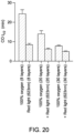
- the rat-sized CO photo-remover developed as described above was tested and in vitro COHb-t 1/2 was measured during treatment of blood with 100% O 2 , with or without red phototherapy, with a CO photo-remover having 8, 20, or 30 layers of membranes.
- red phototherapy is still effective at CO removal when increasing the blood compartment from 8 layers to 30 layers.
- the greatest reduction in COHb-t 1/2 when comparing no red phototherapy to with red phototherapy, is seen for the 8 layer configuration. This is likely due to the ability of the red light to fully penetrate all of the layers of the CO photo-remover. It is hypothesized that there is a maximum thickness where the phototherapy effect diminishes and the light is no longer able to sufficiently penetrate to reach the blood layers.
- the number of layers may define a thickness that is less than 10mm.
- a cooling device may be placed in communication with the blood outlet port to selectively cool the outlet blood to a predetermined temperature.
Landscapes
- Health & Medical Sciences (AREA)
- Heart & Thoracic Surgery (AREA)
- Vascular Medicine (AREA)
- Engineering & Computer Science (AREA)
- Biomedical Technology (AREA)
- General Health & Medical Sciences (AREA)
- Veterinary Medicine (AREA)
- Public Health (AREA)
- Life Sciences & Earth Sciences (AREA)
- Animal Behavior & Ethology (AREA)
- Anesthesiology (AREA)
- Hematology (AREA)
- Cardiology (AREA)
- Urology & Nephrology (AREA)
- Emergency Medicine (AREA)
- Chemical & Material Sciences (AREA)
- Chemical Kinetics & Catalysis (AREA)
- Manufacturing & Machinery (AREA)
- Pathology (AREA)
- Nuclear Medicine, Radiotherapy & Molecular Imaging (AREA)
- Radiology & Medical Imaging (AREA)
- External Artificial Organs (AREA)
Description
- Carbon monoxide (CO) poisoning impairs tissue oxygenation as CO avidly binds to hemoglobin (Hb) to form carboxyhemoglobin (COHb), which cannot transport oxygen. Currently, treatment of CO poisoning involves breathing 100% oxygen to attempt to rapidly remove CO. Hyperbaric oxygen therapy and/or hyperventilation therapy or exercise can further increase the rate of CO elimination but the necessary facilities and equipment may be not be readily available. Visible light is also known to photodissociate CO from Hb, with a single photon dissociating one CO molecule from Hb.
- Smyczynski suggested in
Unites States Patent No. 8,858,880 that light radiation at 540 nanometers (nm) and/or 570 nm could be used to treat CO poisoning by photodissociating COHb in blood passing through an extracorporeal gas exchanger. The treatment system of Smyczynski involves removing and recirculating anticoagulated blood from a patient through an extracorporeal oxygenator. The blood passing through the extracorporeal oxygenator is irradiated with light from a laser at either 540 nm and/or 570 nm. The extracorporeal oxygenator is designed such that the blood-light contact surface is as large as possible because the 540 nm and/or 570 nm light does not penetrate deeply into the blood stream before becoming completely absorbed. The 540 nm and 570 nm light wavelengths are chosen by Smyczynski because these wavelengths align with peaks in the COHb absorption spectra. -
JP 8-131543 CA 900403 discloses a mass transfer device having a microporous, spirally wound hollow fibre membrane.US 8,858,880 B2 discloses an extracorporeal photodynamic blood illumination (irradiation) for the treatment of carbon monoxide poisoning. - The present invention is defined by the appended claims. The present disclosure provides systems and non-claimed methods for extracorporeal CO removal using phototherapy. In particular, systems and non-claimed methods are provided for a extracorporeal phototherapy system that emits light onto opposing sides of an oxygenator that includes a plurality of microporous hollow fiber membranes arranged in layers to photodissociate CO from Hb.
- In one aspect, the present disclosure provides an extracorporeal phototherapy system for removing carbon monoxide from whole blood. The extracorporeal phototherapy system includes an oxygenator having a plurality of membrane layers each with a plurality of microporous hollow fiber membranes. The plurality of microporous hollow fiber membranes each include an external surface and an internal channel. Each of the plurality of microporous membrane layers is rotationally offset with respect to an adjacent layer. The oxygenator further includes a gas inlet port in fluid communication with a first end of the internal channels, a gas outlet port in fluid communication a second end of the internal channels, a blood inlet port in fluid communication with the external surfaces, and a blood outlet port in fluid communication with the external surfaces. The extracorporeal phototherapy system further includes a light source configured to output light and arranged to emit the light output by the light source onto at least one surface of the oxygenator.
- In one aspect, the present disclosure provides an extracorporeal phototherapy system for removing carbon monoxide from whole blood. The extracorporeal phototherapy system includes an oxygenator having a plurality of membrane layers, a gas inlet port configured to provide fluid communication through internal channels formed in each of the plurality of membrane layers and to a gas outlet port, and a blood inlet port configured to provide fluid communication around external surfaces defined by each of the plurality of membrane layers and to a blood outlet port. The extracorporeal phototherapy system further includes a first light source configured to output light and arranged to emit the light output by the first light source onto a first side of the oxygenator, and a second light source configured to output light and arranged to emit the light output by the second light source onto a second side of the oxygenator opposite to the first side.
- In one aspect, the present disclosure provides a non-claimed method of removing carbon monoxide from whole blood. The method includes flowing whole blood over a plurality of microporous hollow fibers arranged within an oxygenator, flowing oxygen through the plurality microporous hollow fibers, and emitting light from a light source onto opposing sides of the plurality of microporous hollow fibers to photodissociate carboxyhemoglobin in the whole blood.
- The foregoing and other aspects and advantages of the invention will appear from the following description. In the description, reference is made to the accompanying drawings which form a part hereof, and in which there is shown by way of illustration a preferred embodiment of the invention. Such embodiment does not necessarily represent the full scope of the invention, however, and reference is made therefore to the claims and herein for interpreting the scope of the invention.
- The invention will be better understood and features, aspects and advantages other than those set forth above will become apparent when consideration is given to the following detailed description thereof. Such detailed description makes reference to the following drawings which may not be drawn to scale.
-
Fig. 1 is a perspective schematic illustration of a extracorporeal phototherapy system according to the present disclosure. -
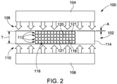
Fig. 2 is a front view of the extracorporeal phototherapy system ofFig. 1 . -
Fig. 3 is a schematic illustration of a parallel porting configuration of the extracorporeal phototherapy system ofFig. 1 . -
Fig. 4 is a schematic illustration of a series porting configuration of the extracorporeal phototherapy system ofFig. 1 . -
Fig. 5 is a top plan view of the extracorporeal phototherapy system ofFig. 1 illustrating blood and gas ports. -
Fig. 6 is a top plan view of the extracorporeal phototherapy system ofFig. 1 illustrating blood ports and channels. -
Fig. 7 is a perspective schematic illustration of a cylindrical configuration of an comparative example of an extracorporeal phototherapy system according to the present disclosure. -
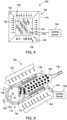
Fig. 8 is a top plan view of the extracorporeal phototherapy system ofFig. 1 illustrating a cooling device connected to the blood outlet port. -
Fig. 9 is a perspective schematic illustration of the cylindrical configuration of the extracorporeal phototherapy system ofFig. 7 illustrating a cooling device connected to the blood outlet port. -
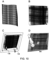
Fig. 10A is a top view of one layer of microporous hollow fiber membranes obtained from a cardiopulmonary bypass oxygenator. -
Fig. 10B is a top view of multiple layers of microporous hollow fiber membranes being rotationally offset from each other. -
Fig. 10C is a top view of the multiple layers ofFig. 10B sealed in a plexiglass housing having ports for gas and blood flow. -
Fig. 10D is a top view of the multiple layers sealed in the housing ofFig. 10C illustrating two sealed compartments formed for blood flow and gas flow. -
Fig. 11A is a schematic illustration of a test setup used to test a developed extracorporeal phototherapy system using human blood. -
Fig. 11B is a schematic illustration of a test setup used to test a developed extracorporeal phototherapy system in a rat study. -
Fig. 12 is a graph illustrating oxygen transfer as a function of blood flow for three different oxygenator devices including a developed oxygenator (photo-ECCOR). -
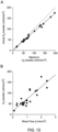
Fig. 13A is a graph illustrating actual oxygen transfer as a function of maximum oxygen transfer for a tested extracorporeal phototherapy system with human blood. -
Fig. 13B is a graph illustrating oxygen transfer as a function of blood flow for the tested extracorporeal phototherapy system with human blood. -
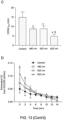
Fig. 13C is a graph illustrating COHb half-life for a tested extracorporeal phototherapy system on human blood with no phototherapy, blue phototherapy, green phototherapy, and red phototherapy on human blood. -
Fig. 13D is a graph illustrating eliminated carbon monoxide as a function of time for the tested extracorporeal phototherapy system on human blood with no phototherapy, blue phototherapy, green phototherapy, and red phototherapy. -
Fig. 14A is a perspective view of a developed light source including four light emitting diodes used in the testing of the extracorporeal phototherapy system. -
Fig. 14B is a front view of the develop light source ofFig. 14A with heat sinks installed on opposing sides of an oxygenator. -
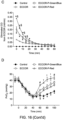
Fig. 15A is a graph illustrating eliminated carbon monoxide as a function of time on carbon-monoxide-poisoned rats with no phototherapy, extracorporeal oxygenation, extracorporeal phototherapy with green/blue light, and extracorporeal phototherapy with red light. -
Fig. 15B is a graph illustrating exhaled carbon monoxide as a function of time on carbon-monoxide-poisoned rats with no phototherapy, extracorporeal oxygenation, extracorporeal phototherapy with green/blue light, and extracorporeal phototherapy with red light. -
Fig. 15C is a graph illustrating COHb percentage as a function of time on carbon-monoxide-poisoned rats with no phototherapy, extracorporeal oxygenation, extracorporeal phototherapy with green/blue light, and extracorporeal phototherapy with red light. -
Fig. 15D is a graph illustrating COHb half-life on carbon-monoxide-poisoned rats with no phototherapy, extracorporeal oxygenation, extracorporeal phototherapy with green/blue light, and extracorporeal phototherapy with red light. -
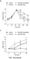
Fig. 16A is a graph illustrating COHb percentage and COHb half-life as a function of time in rats after severe carbon monoxide poisoning with no phototherapy, extracorporeal oxygenation, extracorporeal phototherapy with green/blue light, and extracorporeal phototherapy with red light. -
Fig. 16B is a graph illustrating eliminated carbon monoxide from the rats as a function of time in rats after severe carbon monoxide poisoning with no phototherapy, extracorporeal oxygenation, extracorporeal phototherapy with green/blue light, and extracorporeal phototherapy with red light. -
Fig. 16C is a graph illustrating eliminated CO from the oxygenator as a function of time in rats after severe carbon monoxide poisoning with no phototherapy, extracorporeal oxygenation, extracorporeal phototherapy with green/blue light, and extracorporeal phototherapy with red light. -
Fig. 16D is a graph illustrating normal mixed venous oxygen tension as a function of time in rats after severe carbon monoxide poisoning with no phototherapy, extracorporeal oxygenation, extracorporeal phototherapy with green/blue light, and extracorporeal phototherapy with red light. -
Fig. 16E is a graph illustrating lactate as a function of time in rats after severe carbon monoxide poisoning with no phototherapy, extracorporeal oxygenation, extracorporeal phototherapy with green/blue light, and extracorporeal phototherapy with red light. -
Fig. 16F is a graph illustrating change in base excess values as a function of time in rats after severe carbon monoxide poisoning with no phototherapy, extracorporeal oxygenation, extracorporeal phototherapy with green/blue light, and extracorporeal phototherapy with red light. -
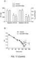
Fig. 17A is a flow chart of lung injury and carbon monoxide poisoning in a rat model. -
Fig. 17B is a graph illustrating percent survival after lung injury and carbon monoxide poisoning in rats with no phototherapy and with extracorporeal phototherapy with red light. -
Fig. 17C is a graph illustrating a ratio between PaO2 and FiO2 and compliance of the respirator system at baseline and at the end of carbon monoxide poisoning with no phototherapy and with extracorporeal phototherapy with red light. -
Fig. 17D is a graph illustrating pH as a function of time after lung injury and carbon monoxide poisoning in rats with no phototherapy and with extracorporeal phototherapy with red light. -
Fig. 17E is a graph illustrating partial pressure of oxygen as a function of time after acute lung injury and carbon monoxide poisoning in rats with no phototherapy and with extracorporeal phototherapy with red light. -
Fig. 17F is a graph illustrating oxygen hemoglobin percentage as a function of time after acute lung injury and carbon monoxide poisoning in rats with no phototherapy and with extracorporeal phototherapy with red light. -
Fig. 17G is a graph illustrating partial pressure of carbon dioxide as a function of time after acute lung injury and carbon monoxide poisoning in rats with no phototherapy and with extracorporeal phototherapy with red light. -
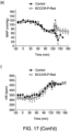
Fig. 17H is a graph illustrating mean arterial pressure as a function of time after acute lung injury and carbon monoxide poisoning in rats with no phototherapy and with extracorporeal phototherapy with red light. -
Fig. 17I is a graph illustrating heart rate as a function of time after acute lung injury and carbon monoxide poisoning in rats with no phototherapy and with extracorporeal phototherapy with red light. -
Fig. 17J is a graph illustrating lactate as a function of time after acute lung injury and carbon monoxide poisoning in rats with no phototherapy and with extracorporeal phototherapy with red light. -
Fig. 17K is a graph illustrating COHb percentage as a function of time after acute lung injury and carbon monoxide poisoning in rats with no phototherapy and with extracorporeal phototherapy with red light. -
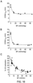
Fig. 18A is a graph illustrating COHb half-life as a function of blood flow rate in carbon-monoxide-poisoned rats with extracorporeal phototherapy with red light and 100% oxygen. -
Fig. 18B is a graph illustrating COHb half-life as a function of blood flow rate in carbon-monoxide-poisoned rats with extracorporeal phototherapy with red light and air. -
Fig. 18C is a graph illustrating percent carbon monoxide extraction as a function of blood flow rate in carbon-monoxide-poisoned rats with extracorporeal phototherapy with red light. -
Fig. 19 is a graph illustrating blood temperature as a function of time for extracorporeal oxygenation, extracorporeal phototherapy with green light, extracorporeal phototherapy with blue light, and extracorporeal phototherapy with red light. -
Fig. 20 is a graph illustrating carbon monoxide half-life as a function of a number of layers in a blood compartment of an oxygenator with extracorporeal oxygenation using oxygen and extracorporeal phototherapy using red light. -
Fig. 21 is a graph illustrating carbon monoxide half-life as a function of blood flow rate in a human-sized oxygenator with extracorporeal oxygenation using oxygen and extracorporeal phototherapy using red light. -
Fig. 22 is a graph illustrating blood temperature increase as a function of blood flow rate in a human-sized oxygenator with extracorporeal phototherapy using red light. -
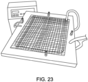
Fig. 23 is a perspective view of a developed human-sized oxygenator. -
Fig. 24 is a graph illustrating carbon monoxide half-life in the human-sized oxygenator ofFig. 23 with extracorporeal oxygenation using oxygen and extracorporeal phototherapy using red light. - The term "visible light" as used herein refers to a portion of the electromagnetic spectrum, generally bound between wavelengths of approximately 380 nanometers (nm) and approximately 750 nm, that is visible to the human eye. One of skill in the art would recognize that the wavelength range of visible light will vary from person to person depending on one's vision. Thus, the range from 380 nm to 750 nm is a generally accepted range and is not meant to be definitively limiting in any way.
- Carbon monoxide intoxication is a leading cause of poisoning related deaths and results in more than 50,000 visits to emergency departments in the United States each year. Exposure to carbon monoxide is often associated with inhalation of other chemicals and particulates, which can damage the airways and alveoli, resulting in acute lung injury and respiratory failure. In soldiers and firefighters, acute respiratory distress syndrome (ARDS) secondary to trauma and burns can be present. Whenever CO poisoning is associated with impaired gas exchange in the lungs, treatment with either normobaric or hyperbaric oxygen might be less effective or noxious.
-
Figs. 1 and2 illustrate one non-limiting example of aextracorporeal phototherapy system 100 according to the present disclosure. In general, theextracorporeal phototherapy system 100 may include at least one light source arranged to emit light at a surface of anoxygenator 102 to promote photodissociation of carboxyhemoglobin (COHb). In the illustrated non-limiting example, theextracorporeal phototherapy system 100 may include a firstlight source 104 and a secondlight source 106 arranged on opposing sides of theoxygenator 102. That is, the firstlight source 104 may be arranged to emit light onto afirst side 108 of theoxygenator 102 and the secondlight source 106 may be arranged to emit light onto asecond side 110 of theoxygenator 102. - In some non-limiting examples, the first
light source 104 and the secondlight source 106 may be configured to emit coherent light. In some non-limiting examples, the firstlight source 104 and the secondlight source 106 may be configured to emit non-coherent light. In some non-limiting examples, the firstlight source 104 and the secondlight source 106 may each be in the form of an array of one or more light emitting diodes (LEDs). In some non-limiting examples, the firstlight source 104 and the secondlight source 106 may each be configured to output light at with a wavelength in the visible spectrum. In some non-limiting examples, the firstlight source 104 and the secondlight source 106 may each be configured to output light at with a wavelength greater than 600 nanometers (nm). In some non-limiting examples, the firstlight source 104 and the secondlight source 106 may each be configured to output light at with a wavelength between than 600 nm and 650 nm. - As described herein, the use of red light (e.g., light with a wavelength generally between 600 nm and 650 nm) may provide increased penetration depth into the
oxygenator 102 as well as result in less heating of the blood flowing through theoxygenator 102, when compared to irradiation with light of a lower wavelength (e.g., 450 nm or 532 nm). The increased penetration depth of the red light may provide increased CO elimination from the blood in theoxygenator 102, when compared to irradiation with light of a lower wavelength. - In the illustrated non-limiting example, the
oxygenator 102 includes a plurality ofmembrane layers 112 enclosed within ahousing 114. The plurality ofmembrane layers 112 each include a plurality of microporoushollow fiber membranes 116 that are arranged in a planar shape and parallel to one another. In general, the plurality of microporoushollow fiber membranes 116 may be fabricated from a material that provides a high diffusion coefficient for CO and oxygen (O2). For example, a silicone material may define a CO diffusion coefficient that is too low to enable effective removal of CO from the treated blood in a single pass. In some non-limiting examples, the plurality of hollow fiber membranes may be fabricated from a microporous polypropylene or a polymethylpentene material, which provide efficient CO removal and oxygenation. - In the illustrated non-limiting example, each of the plurality of
membrane layers 112 may be rotationally offset with respect to an adjacent layer. For example, each of the plurality ofmembrane layers 112 may be rotated ninety degrees with respect to the adjacent layers. In this way, for example, the plurality of microporoushollow fiber membranes 116, which extend generally parallel to one another within a respective one of the plurality ofmembrane layers 112, may define a generally checkered pattern. That is, one layer of the plurality of microporoushollow fiber membranes 116 may extend in a first direction and an adjacent layer, either above and/or below, may extend in a second direction perpendicular to the first direction. - Each of the plurality of microporous
hollow fiber membranes 116 may include an external surface 118 and aninternal channel 120. Theinternal channels 120 may extend axially along each of the plurality of microporoushollow fiber membranes 116. In general, the plurality of microporoushollow fiber membranes 116 may be designed to allow diffusion of O2 and CO between blood flowing over the external surfaces 118 and gas flowing (e.g., O2) through theinternal channels 120. - With reference to
Fig. 2 in particular, theoxygenator 102 may be designed to provide efficient phototherapy for photodissociation of COHb in CO-poisoned blood (e.g., whole blood). In conventional oxygenators, an air gap may be formed between the first layer of membranes and a treatment surface 121 (e.g., top and bottom surfaces of theoxygenator 102 from the perspective ofFig. 2 ). During operation, a blood layer may form in this air gap and, since this blood layer is not flowing over a membrane layer, the efficiency of phototherapy to eliminate CO from the blood may be significantly reduced. That is, although the phototherapy may aid in photodissociating COHb, oxygenation and removal of the CO, which are facilitated by the plurality of microporoushollow fiber membranes 116, must be provided to prevent rebinding of the CO to hemoglobin. As such, theoxygenator 102 may be designed to reduce or eliminate an air gap A formed between a treatment surface 121 (i.e., an incident on which the firstlight source 104 and the secondlight source 106 emit light) and the layer of the plurality ofmembrane layers 112 adjacent to thetreatment surface 121. The air gap A may be at the top and the bottom. In this way, for example, theoxygenator 102 may ensure that the emitted light is emitted onto blood flowing over one of the plurality of microporoushollow fiber membranes 116. - In some non-limiting examples, to further increase the efficacy of the phototherapy elimination of CO from blood in the
oxygenator 102, theoxygenator 102 may be designed with a thickness T that ensures that the light emitted by the firstlight source 104 and the secondlight source 106 may penetrate through to all of the plurality of membrane layers 112. In general, a number of layers in the plurality ofmembrane layers 116 may define the thickness T (e.g., via an outer diameter defined by the external surfaces 118). As such, in some non-limiting examples, theoxygenator 102 may be designed with a predetermined number of layers in the plurality ofmembrane layers 112 to achieved a desired thickness T. In some non-limiting examples, the thickness T may be less than 15 millimeters (mm). In some non-limiting examples, the thickness T may be less than 10 mm. - In general, the
oxygenator 102 may be configured to exchange CO and O2 via diffusion through the plurality of microporoushollow fiber membranes 116 in blood flowing over the external surfaces 118. To facilitate blood flow and gas flow through theoxygenator 102, thehousing 114 may be provided with one or more ports to facilitate connections to flow devices (e.g., pumps, gas tanks, etc.) arranged externally from theoxygenator 102. Alternatively or additionally, one or more of theoxygenators 102 may be placed in parallel (see, e.g.,Fig. 3 ) or in series (see, e.g.,Fig. 4 ). - With reference to
Fig. 5 in particular, in general, theoxygenator 102 may be separated into ablood compartment 124, agas inlet compartment 126, and agas outlet compartment 128. In some non-limiting examples, an adhesive (e.g., a silicone adhesive) may be applied to seal theblood compartment 124 from thegas inlet compartment 126 and thegas outlet compartment 128. The seal between theblood compartment 124 and thegas inlet compartment 126 may allow a first end 130 of the plurality of microporoushollow fiber membranes 116 to protrude intogas inlet compartment 126. The seal between theblood compartment 124 and thegas outlet compartment 128 may allow a second end 132 of the plurality of microporoushollow fiber membranes 116 to protrude into thegas outlet compartment 128. In this way for example, the first ends 130 and the second ends 132 of the plurality of microporoushollow fiber membranes 116 may be sealed from theblood compartment 124 to allow gas flow through theinternal channels 120 and prevent blood from flowing into theinternal channels 120. A remainder of the plurality of microporoushollow fiber membranes 116 not sealed off by thegas inlet compartment 126 and thegas outlet compartment 128 may be arranged within theblood compartment 124. Thus, theblood compartment 124 may provide a sealed compartment within which blood may flow over the external surfaces 118 of the plurality of microporoushollow fiber membranes 116. - In the illustrated non-limiting example, the
housing 114 may include agas inlet port 134, agas outlet port 136, ablood inlet port 138, and ablood outlet port 140. Thegas inlet port 134 may be arranged within thegas inlet compartment 126 and may be in fluid communication with the first ends 130 of theinternal channels 120. Thegas outlet port 136 may be arranged within thegas outlet compartment 136 and may be in fluid communication with the second ends 132 of theinternal channels 120. Theblood inlet port 138 and theblood outlet port 140 may be arranged within theblood outlet compartment 124. In general, an arrangement of thegas inlet port 134, thegas outlet port 136, theblood inlet port 138, and theblood outlet port 140 may provide gas flow and blood flow in a common direction (e.g., diagonal from upper left to lower right from the perspective ofFig. 5 ). In this way, for example, theoxygenator 102 may aid in preventing or minimizing a rebinding rate of COHb. - In some non-limiting examples, the
gas inlet port 134 may be in fluid communication with a fluid source configured to supply gas to thegas inlet port 134 at a predetermined flow rate. In some non-limiting examples, the fluid source may be configured to supply 100% O2 to thegas inlet port 134. Using 95% oxygen and 5% CO2 may be desirable in some settings. If removing CO2 with the extracorporeal device, removal of CO from the lungs will be impaired based on breathing, with a null effect on overall CO removal rate as a result. Providing the device with some CO2 (50%) will not materially affect arterial PCO2, respiratory drive and the like. In some non-limiting examples, the fluid source may be configured to supply air to thegas inlet port 134. In general, theblood inlet port 138 may be in fluid communication with a pump, or another fluid flow device, that is configured to draw whole blood from a patient or a reservoir connected to the patient (e.g., via cannulas inserted into one or more veins of the patient). The whole blood removed from the patient may flow through theoxygenator 102 over the external surfaces 118 of the plurality of microporoushollow fiber membranes 116 to theblood outlet port 140. Theblood outlet port 140 may be in fluid communication with the patient (e.g., via one or more cannulas inserted into one or more veins of the patient). As such, the whole blood may be recirculated through theoxygenator 102 and the patient. - In general, the gas flow rate supplied to the
gas inlet port 134 may be higher than a blood flow rate supplied to theblood inlet port 138. In some non-limiting examples, a ratio between the gas flow rate supplied to thegas inlet port 134 to the blood flow rate supplied to theblood inlet port 138 may be greater than 5:1. In some non-limiting examples, a ratio between the gas flow rate supplied to thegas inlet port 134 to the blood flow rate supplied to theblood inlet port 138 may be greater than 10:1. If the ratio between GAS and BLOOD flow rates is appreciably elevated, an undesirable air gas embolism can be introduced into blood. Up to 10 times higher gas flow than blood flow can be used as a rule of thumb. For example, 1 L/min blood flow can be used with 10 L/min gas flow, 500 ml/min blood flow can be used with 5 L/min gas flow and the like. Of course, other parameters will work beyond this rule of thumb. In some non-limiting examples, the gas flow rate provided to thegas inlet port 134 may provide a partial pressure of O2 (PO2) between 400 millimeters of mercury (mmHg) and 500 mmHg. The high gas flow rates compared to the blood flow rates aid theoxygenator 102 in reducing COHb rebinding rates and provide needed ventilation to expel photodisassociated CO. - During operation, it is important to design the
oxygenator 102 to ensure that blood covers the a substantial portion of the blood compartment surface area. In this way, for example, the surface area for treatment may be expanded to encompass the entire or a substantial portion of theblood compartment 124.Fig. 6 illustrates one non-limiting example where thehousing 114 includes anblood inlet channel 142 connected to theblood inlet port 138 and ablood outlet channel 144 connected to theblood outlet port 140. Theblood inlet channel 142 extends along one side of theblood compartment 124 and theblood outlet channel 144 extend along an opposite side of theblood compartment 124 in a direction that is general parallel to theblood inlet channel 142. In this way, for example, blood may be distributed from theblood inlet port 138 along one side of theblood compartment 124. With the blood distributed along one side of theblood compartment 124, the blood may flow along theblood compartment 124 to the opposing side and into theblood outlet channel 144. Theblood inlet channel 142 and theblood outlet channel 144 may aid in distributing the blood over the entire surface area, or a substantial portion of the surface area, of theblood compartment 124. - In the illustrates non-limiting examples of
Figs. 1-6 theoxygenator 102 defines a generally planar shape (e.g., a thin rectangular prism). In other non-limiting, comparative examples, theoxygenator 102 may be designed in alternative shapes while maintaining the principles and characteristics described herein.Fig. 7 illustrates one non-limiting, comparative example of theextracorporeal phototherapy system 100 where theoxygenator 102 defines a generally cylindrical shape. Similar to the planar design of theoxygenator 102, the cylindrical design of theoxygenator 102 may enable phototherapy to be applied onto two opposing surfaces of theoxygenator 102. In the illustrated non-limiting example, the firstlight source 104 may define a generally annular shape that extends concentrically around an outer surface of theoxygenator 102. The secondlight source 106 may be define a generally rectangular prism shape and may be arranged within an internal surface of theoxygenator 102. In other non-limiting examples, the secondlight source 106 may define alternative shapes (e.g., cylindrical). - In the illustrated non-limiting example, a flow of cooling fluid 145 (e.g., water) may be provided to the second
light source 106 arranged within theoxygenator 102. In this way, for example, cooling may be provided to the blood flowing through theoxygenator 102. The cooling system may be a heat exchanger with cold water that cools entering inlet blood a few degrees Celcius. - In some non-limiting examples, as illustrated in
Figs. 8 and 9 , a cooling device 146 (e.g., a heat exchanger, a photoelectric cooler, an evaporative cooler, etc.) may be placed in fluid communication with theblood outlet port 140 to selectively provide cooling to the blood flow leaving theoxygenator 102 and flowing toward, for example, a patient. Thecooling device 146 may be configured to cool the blood flowing from theblood outlet port 140 to a predetermined temperature (e.g., around body temperature). In some non-limiting examples, thecooling device 146 may be in communication with a controller that is configured to monitor an outlet temperature of the blood flowing from theblood outlet port 140 and control thecooling device 146 to maintain the blood temperature flowing from thecooling device 146 to the predetermined temperature. - One non-limiting example of operation of the
extracorporeal phototherapy system 100 will be described with reference toFigs. 1-9 . In general, theextracorporeal phototherapy system 100 may provide removal of CO from blood in a patient having CO poisoning. For example, theextracorporeal phototherapy system 100 may provide sufficient removal of CO to allow the treatment of CO poisoning in environments where medical care is not easily accessible and breathing O2 is not helping treat the CO poisoning. Typically, to treat a patient having CO poisoning theblood inlet port 138 may be connected to a pump, which is configured to remove whole blood from a patient, and theblood outlet port 140 may be connected to the patient (e.g., via a cannula inserted into a vein of the patient). Thegas inlet port 134 may be connected to a gas supply configured to flow, for example, 100% O2 through theinternal channels 120 of the plurality of microporoushollow fiber membranes 116 to thegas outlet port 136. - With the gas and blood flows connected the
oxygenator 102, the flow of whole blood and oxygen may begin, for example, with the gas flow rate being approximately 5 times greater than or equal to the blood flow rate, or approximately 10 times greater than or equal to the blood flow rate. While the blood and gas are flowing through theoxygenator 102, the firstlight source 104 and the secondlight source 106 may emit light onto opposing sides of theoxygenator 102, specifically, onto treatment surfaces 120 arranged on opposing sides of theblood compartment 124. The light emitted by the firstlight source 104 and the secondlight source 106 may penetrate through the plurality ofmembrane layers 112, for example, due to the thickness T defined by the plurality ofmembrane layers 112 and the penetration capabilities of the light emitted by the firstlight source 104 and the secondlight source 106. The photons emitted by the firstlight source 104 and the secondlight source 106 may be absorbed by COHb in the blood and photodisassociate the COHb into CO and Hb. The firstlight source 104 and/or the secondlight source 106 may be arranged inside of or outside of the oxygenator and/or can also be located on acooling device 146. - Since the partial pressure of oxygen flowing through the
internal channels 120 of the plurality of microporoushollow fiber membranes 116 is much greater than in the blood flowing over the external surfaces 118, oxygen may diffuse through the plurality of microporoushollow fiber membranes 116 to bind to deoxygenated Hb. The CO may diffuse into the plurality of microporoushollow fiber membranes 116 and the gas flow may expel the CO from theoxygenator 102. As such, the design and properties of theextracorporeal phototherapy system 100 may facilitate efficient and effective removal of CO from whole blood in a patient having CO poisoning. - Of note the average human or rat has a blood volume of 6-8% of body weight or for a 75 kg human that is about 5 liters total blood volume. To clean out most of the CO and replace with 02, one must treat 5L to remove 100% of the CO. As a non-limiting example, if one can process vein-to-vein blood extracorporeally at 250 ml/min to remove 90% of CO on a single phototherapy pass, a liter can be processed every 4 minutes.
- The following examples set forth, in detail, ways in which the extracorporeal phototherapy systems described herein may be used or implemented, and will enable one of skill in the art to more readily understand the principles thereof. The following examples are presented by way of illustration and are not meant to be limiting in any way.
- A membrane oxygenator was built with a configuration suitable for blood phototherapy and tested the device in an in vitro model of veno-venous extracorporeal blood circulation. The in vitro circuit for blood circulation consisted of an open reservoir (10 ml syringe), a roller pump (NE-9000-G, Farmingdale, NY), silicone tubing and a membrane oxygenator. Blood entering and exiting the CO photo-remover was collected while the CO photo-remover was perfused with deoxygenated blood and ventilated with 100% oxygen at 1 L/min. For each pair of samples, the actual oxygen transfer and the maximum oxygen transfer were calculated as following:

Maximum O2 transfer (ml/min/m2) = [CmaxO2 (ml/dL) - CpreO2 (ml/dL)] * BF(ml/min/m2),
Where:

CpostO2 (ml/dL) = [Hb (g/dL) * SatpostO2(%) * 1.36(ml/g)/100] + [PpostO2(mmHg)*0.003]; CmaxO2 (ml/dL) = {Hb (g/dL) * [100-COHb(%)-MetHb(%)] * 1.36(ml/g)/1001 + {[760-47-PpostCO2](mmHg)*0.003}; and 
- In all equations 'C' refers to content of oxygen in blood, `pre' refers to blood entering the oxygenator and 'post' refers to blood exiting the oxygenator.
- To create a membrane oxygenator (CO photo-remover) with optimal characteristics for both oxygen transfer, CO removal and venous blood light exposure, a microporous polypropylene membrane for gas exchange was enclosed within and a clear plexiglass case to allow light penetration. The polypropylene membrane was obtained from a disassembled cardiopulmonary bypass oxygenator and cut into 7x7 cm sections as shown in
Fig 10A . Eight sections were placed on top of each other, with each layer rotated 90 degrees relative to the one below as shown inFig. 10B . The edges of the membranes were sealed with silicone rubber adhesive and enclosed in a clear plexiglass case with ports formed therein to provide ablood inlet 138, a blood outlet (not shown), agas inlet 134, and a gas outlet (not shown) as shown inFig. 10C . The configuration of the device was such that two sealed compartments were obtained: a compartment for blood flowing around the hollow fibers, and a compartment for oxygen flowing into the hollow fibers as shown inFig. 10D . The size of the chamber containing the hollow fibers and the blood was 6 centimeters (cm) wide, 6 cm long, and 4 mm in height. Within the chamber, the priming volume for blood was 4 ml, while the remaining volume was occupied by the hollow fibers. The surface area for gas exchange was 0.05 m2 and the total surface area for phototherapy was 72 cm2. - To determine the in vitro oxygenating performance of the CO photo-remover, deoxygenated whole blood was circulated through the CO photo-remover at various flow rates while the device was "ventilated" with 100% oxygen (see
Fig. 11A ). In commercially available extracorporeal membrane oxygenation devices, the partial pressure of oxygen in blood (PO2) exiting the membrane lung is between 400 and 500 mmHg (see, e.g.,Fig. 12 ). The PO2 of the blood entering and exiting the CO photo-remover was 35.5±11.9 and 482±72 mmHg, respectively. The actual oxygen transfer was similar to the maximum oxygen transfer (R2=0.99, Slope=0.86, P<0.0001, seeFig. 13A ) and the oxygen transfer increased linearly with increasing blood flow rate (R2=0.78, P<0.0001, seeFig. 13B ). These results indicate that the CO photo-remover has an oxygen transfer performance equivalent to a commercial device used for cardiopulmonary bypass and extracorporeal membrane oxygenation. - To test whether the newly developed CO photo-remover was an effective approach to treating CO poisoned blood in vitro, human blood was circulated through the device using a roller pump while the membranes were ventilated with 2% CO in nitrogen. After 10-15 minutes, 80-90% of hemoglobin was saturated with CO. The CO photo-remover was then ventilated with 100% oxygen at 100 ml/min and was exposed to LEDs generated blue (460 nm), green (523 nm), red (623 nm) or no light. The developed light sources are shown in
Figs. 14A and 14B . Light emitting diodes (LEDs, Mouser Electronics, Mansfield, TX), with a maximum power of 750 mW, were used to produce green (523 nm), red (623 nm) or blue (460 nm) light. During ECCOR with phototherapy (ECCOR-P), the CO photo-remover was irradiated using a total of 8 LEDs, four on each side of the membrane oxygenator. The irradiance of phototherapy (the light power over the surface area of exposure) was approximately 80 mW/cm2. LEDs were attached to heat sinks, which were ventilated with small fans to dissipate the heat produced during phototherapy (see, e.g.,Fig. 14B ). - Serial samples of blood were collected to measure COHb and to calculate COHb half-life (COHb-t1/2), while CO concentration exiting the CO photo-remover was measured continuously. During circulation of CO poisoned blood through the CO photo-remover, while the device was ventilated with 100% oxygen but was not treated with phototherapy (control), the COHb-t1/2 was 14.9±2.8 min. Compared to control (no exposure to light), addition of either blue or green light reduced COHb-t1/2 by approximately 42% (to 8.7±0.6 min and 8.8±1.6 min for blue or green light, respectively, each with p<0.0001 compared to control, see
Figure 13C ). Exposure of the device to red light reduced COHb-t1/2 to 4.9±1.0 min, reflecting a 67% reduction compared to no light (p<0.0001) and 44% reduction compared to blue or green light (p<0.01 for each comparison). The CO exiting the photo-remover during phototherapy with light (and exposure to 100% oxygen) was greater than during treatment with 100% oxygen alone. Exposure of the CO photo-remover to red light resulted in greater CO elimination than blue or green phototherapy (seeFig. 13D ). These results show that phototherapy increases the rate of CO elimination from blood in vitro and that red light is more effective than blue or green light at enhancing the rate of CO removal. - All animal experiments were approved by the Subcommittee on Research Animal Care of the Massachusetts General Hospital, Boston, Mass. Anesthetized and mechanically ventilated Sprague Dawley rats weighing 400-500 g were tested. Rats were anesthetized with
Isoflurane 5% in oxygen for 3-5 minutes in a plexiglass chamber. Following a tracheostomy, rocuronium (1 mg•kg-1) was injected (i.p.) to induce muscle relaxation and rats were mechanically ventilated (Inspira; Harvard Apparatus, Holliston, Mass). Volume-controlled ventilation was provided at a respiratory rate of 40 breaths•min-1, a tidal volume of 10 mL•kg-1, positive end expiratory pressure (PEEP) of 2 cmH2O. Anesthesia was maintained with 1-2% isoflurane and continuous muscle relaxation was provided with rocuronium (2-4 mg•kg-1•h-1). Airway pressure was continuously monitored, as well as end tidal CO2 (ETCO2) which was measured by a capnometer (PhysioSuite, CapnoScan End-Tidal CO2 Monitor, Kent Scientific, Torrington, Conn). - The right carotid artery was cannulated with a PE20 catheter for blood sampling and arterial blood pressure monitoring. A bolus of heparin (200 UI•kg-1) and subsequent continuous infusion at 100 UI•kg-1•h-1 was administered for blood anticoagulation. A custom-made 4-hole, 16-gauge cannula was placed in the right femoral vein and a 18-gauge cannula (Introcan Safety, B Brown Medical Inc., Irvine, CA) was placed in the right jugular vein. Fluid resuscitation was maintained infusing 0.9% Saline at a rate of 8 to 12 mL•kg-1•h-1.
- To determine whether the CO photo-remover was able to increase the rate of CO elimination from blood in vivo, the device was tested in a rat model of CO poisoning (see
Fig. 11B ). Anesthetized and mechanically ventilated rats were poisoned by breathing 2000 ppm CO in air for 30 min. All animals underwent veno-venous extracorporeal blood circulation with blood flow rate ranging from 50 to 100 ml/kg/min (which corresponds to approximately 15-30% of the rat's cardiac output) and were treated by breathing 100% oxygen while the CO photo-remover was provided with: 1) neither gas nor light (control); 2) gas flow (95% O2 and 5% CO2) but no phototherapy (ECCOR); 3) gas flow and phototherapy with combined green and blue light (ECCOR-P-Green/Blue); 4) gas flow and phototherapy with red light (ECCOR-P-Red). - In control animals, neither gas flow nor light was applied to the CO-photo-remover. No CO was eliminated by the device (see
Fig. 15A ) and the COHb-t1/2 was 17.7±1.2 min. Addition of gas flow, but no light, to the CO photo-remover (ECCOR) reduced COHb-t1/2 by 28% (12.8±0.6 vs. 17.7±1.2 min, p<0.0001 seeFigs. 15A and 15B ). As illustrated inFigs. 15B-15D , irradiation of the device with green and blue light produced a 47% reduction in COHb-t1/2 compared to controls (9.4±0.8 vs. 17.7±1.2 min, p<0.0001) and a 27% reduction in COHb-t1/2 compared to ECCOR with gas, but without light (9.4±0.8 vs. 12.8±0.6 min p<0.001). Red light produced a 53% reduction in COHb-t1/2 compared to control (8.6±0.5 vs. 17.7±1.2 min,p<0.0001) and a 33% reduction in COHb-t1/2 compared to ECCOR with gas but without light (8.6±0.5 vs. 12.8±0.6 min, p<0.001). These results show that the extracorporeal removal of CO using phototherapy increases the rate of blood CO elimination in vivo. - Because the CO eliminated by the CO photo-remover during phototherapy (ECCOR-P-Green/Blue and ECCOR-P-Red) was significantly higher than the CO eliminated without phototherapy (ECCOR - only gas flow), there was less CO remaining to be exhaled from the lungs of treated animals compared to control rats (see
Fig. 15B ). Taken together, these results show that the extracorporeal removal of CO using phototherapy increases the rate of blood CO elimination in vivo. - To determine whether the faster reduction of COHb observed with the combination of ECCOR and phototherapy has a beneficial effect on tissue oxygenation after CO poisoning, a more severe model of CO poisoning was developed. Rats were anesthetized and poisoned by breathing 2000 ppm CO in air for 45 minutes and developed tissue hypoxia and lactic acidosis. During CO poisoning, mean arterial pressure (MAP) decreased from 116±14 to 83±9 mmHg (p<0.0001) and heart rate (HR) increased from 379±38 to 445±40 beats per minute (p<0.0001). Arterial levels of COHb increased to 58.5±1.6% at the end of the CO poisoning period, while venous PO2 decreased from 40.8±3.4 to 13.5±2.7 mmHg (p<0.0001). Lactate concentration increased from 2.5±0.5 before CO poisoning to 7.6±0.4 mmol/L (p<0.0001) at the end of 45 minutes and produced acidosis, as suggested by a decreased arterial base excess (from 0.9±1.9 to -7.7±2.3 mmol/L, p<0.0001).
- After poisoning, animals were treated by breathing air so as to mimic a situation of reduced arterial oxygenation, as may occur in a patient with acute lung injury (ARDS) and impaired gas exchange. All animals were treated with veno-venous extracorporeal blood circulation with blood flow rates ranging from 50 to 100 ml/kg/min. In control animals the device was provided with neither gas flow nor phototherapy and the COHb-t1/2 was 54.9±2.7 min (
Fig. 16A ). Treatment with ECCOR and gas flow, but no phototherapy, reduced COHb-t1/2 by 44% (54.9±2.7 vs. 31.2±1.5 min p<00001). Treatment with ECCOR, gas flow and combined green and blue light (ECCOR-P-Green/Blue) reduced COHb-t1/2 by 67% compared to control animals (54.9±2 vs. 18.0±0.7 min, p<0.0001). Treatment with ECCOR gas flow and red light (ECCOR-P-Red) reduced COHb-t1/2 by 79% compared to controls (54.9±2 vs. 11.6±1.4 min, p<0.0001) and by 35% compared to treatment with ECCOR-P-Green/Blue (18.0±0.7 vs. 11.6±1.4 min, p=0.014). - At the beginning of the treatment period, the elimination of CO from the lungs of CO-poisoned animals was similar in all four groups (
Fig. 16B ). In later phases of the treatment period, the CO exhaled from the lungs of control animals was higher than in treated animals, as a greater amount of COHb remained in the circulation and more CO was available to be removed by the lungs. The elimination of CO from the CO photo-remover was significantly greater using ECCOR with red light than with ECCOR alone or with ECCOR with green and blue light (seeFig. 16C ). - Animals treated with ECCOR-P-Red or ECCOR-P-Green/Blue had a faster return of venous PO2 to baseline (see
Fig. 16D ) compared to control animals (for which neither gas flow nor phototherapy was applied to the device). Lactate clearance was also faster in ECCOR-P-treated animals (seeFig. 16E ), resulting in a more rapid return of base excess to baseline values and correction of metabolic acidosis (seeFig. 16F ). - Taken together, these results show that in CO-poisoned rats breathing room air, veno-venous extracorporeal removal of CO using phototherapy dramatically increases the rate of CO elimination and that red light is more effective than the combination of green and blue light in removing CO from the blood of CO poisoned rats. The faster removal of CO from circulating blood is associated with improved tissue oxygenation, as well as faster clearance of systemic lactate and correction of metabolic acidosis.
- In rats that were poisoned with CO, the use of ECCOR-P-Red doubled the rate of CO elimination compared to rats breathing 100% oxygen and produced a five-fold increase in the rate of CO removal in rats breathing room air. It was hypothesized that ECCOR-P-Red would be particularly beneficial in a situation of limited gas exchange, such as may occur in patients with acute lung injury. An intravenous injection of oleic acid was used to produce a rat model of acute lung injury and impaired gas exchange (see
Fig. 17A ). This model has a high degree of reproducibility and the histopathological and physiological changes caused by oleic acid are similar to those seen in patients with ARDS. After oleic acid injection, animals were poisoned with 2000 ppm CO for 45 minutes. All of the control animals, treated with 100% oxygen but no extracorporeal circulation, died within 46 minutes after the initiation of treatment. In contrast, all animals treated with 100% oxygen ventilation and ECCOR-P-Red (initiated after the poisoning) survived until the endpoint of the study (60 minutes after the initiation of treatment; seeFig. 17B ). The severity of the acute lung injury and the CO poisoning level was comparable in the two groups: 1) The ratio between PaO2 and FiO2 (P/F ratio) and the respiratory system compliance (Crs) were significantly reduced at the end of the CO poisoning (and beginning of treatment) in both groups (seeFig. 17C ); 2) Arterial pH, PO2 and O2Hb levels similarly decreased during lung injury and CO poisoning (seeFigs. 17D-17F ). The partial pressure of carbon dioxide (PaCO2) initially increased due to lung injury, and then decreased during CO poisoning, likely due to reduced CO2 production in the setting of tissue hypoxia (seeFig. 17G ); 3) Prior to treatment, mean arterial pressure, heart rate and the arterial blood lactate levels were similar in both groups (see Figs. 17H-17L). - In oleic acid treated and CO poisoned rats ventilated with 100% oxygen, the circulating COHb levels decreased faster in rats treated with ECCOR-P-Red than in rats that were treated with 100% oxygen alone. (COHb-t1/2: 11.6±2.4 vs. 28.5±3.5 min, p=0002, see Fig. 17M). Compared to control rats, rats treated with ECCOR-P-Red had significantly higher pHa and O2Hb levels and lower levels of PaCO2 during the treatment period. These results show that, in rats with acute lung injury and CO poisoning, treatment with the veno-venous extracorporeal removal of CO using phototherapy markedly increased the rate of CO elimination and improved overall survival.
- To assess whether the efficacy of CO removal by veno-venous ECCOR-P is altered by changing the rate of blood circulating through the device, rats were poisoned with 2000 ppm CO in air and then treated with 100% oxygen and ECCOR-P-Red at different blood flow rates. Treatment with ECCOR-P-Red increased the rate of CO elimination at blood flows ranging from 10 to 85 ml/kg/min (see
Fig. 18A ). The relationship between COHb-t1/2 and the veno-venous extracorporeal blood flow rate is described by an exponential decay curve (Y=(Y0-Plateau)•exp(-K•X)+Plateau, (Figure 6A, R2=0.99). When the blood flow was greater than 20 ml/kg/min (which corresponds to approximately 5-10% of the rat's cardiac output), a CO removal plateau was reached (COHb-t1/2 plateau = 8.6 min), indicating that a further increase in the blood flow rate did not increase the rate of CO elimination. - To investigate whether ECCOR-P is effective at a wide range of blood flow rates in animals breathing a lower concentration of oxygen, rats were poisoned with 2000 ppm CO in air and then treated by breathing air instead of 100% oxygen. The rats were treated with ECCOR-P-Red at different blood flow rates. ECCOR-P-Red was effective at blood flows ranging from 10 to 85 ml/kg/min, with a COHb-t1/2 plateau of 12.4 min (see
Fig. 18B , R2=0.97). - At each blood flow rate, the performance of the CO photo-remover was assessed by measuring the amount of CO in the blood entering the device and the amount of CO in the gas effluent. At high blood flow rates, approximately 10% of the CO entering the device was eliminated. In contrast, at lower blood flow rates, up to 35% of the CO entering the device was eliminated (see
Fig. 18C ). These results show that the extracorporeal removal of CO using phototherapy is highly effective at a wide range of blood flow rates, and that at low blood flow rates more CO is eliminated per unit of blood entering the CO photo-remover. - The rat-sized CO photo-remover developed as described above was tested to assess the effect of wavelength on blood temperature at the blood outlet port. The size of the blood compartment was 6cm × 6cm and 8 layers of gas exchange membranes were used. The gas exchange area was 0.05m2. The CO photo-remover was illuminated with 4 LEDs from the top and at the bottom. Blood volume = 20ml, Hb concentration = 6.0-7.0 g/dL, blood flow = 10 ml/min, gas flow = 100 ml/min.
- As illustrated in
Fig. 19 , the use of no phototherapy resulted in the blood temperature slightly decreasing over time, while all of the phototherapy tests resulted in an increase in blood temperature. However, the use of red light resulted in the lowest increase in blood temperature, when compared to the use of green light and blue light, which further demonstrates the efficacy of using ECCOR-P treatment with red light to eliminate CO from blood. - The rat-sized CO photo-remover developed as described above was tested and in vitro COHb-t1/2 was measured during treatment of blood with 100% O2, with or without red phototherapy, with a CO photo-remover having 8, 20, or 30 layers of membranes. As illustrated in
Fig. 20 , red phototherapy is still effective at CO removal when increasing the blood compartment from 8 layers to 30 layers. The greatest reduction in COHb-t1/2, when comparing no red phototherapy to with red phototherapy, is seen for the 8 layer configuration. This is likely due to the ability of the red light to fully penetrate all of the layers of the CO photo-remover. It is hypothesized that there is a maximum thickness where the phototherapy effect diminishes and the light is no longer able to sufficiently penetrate to reach the blood layers. In some non-limiting examples, the number of layers may define a thickness that is less than 10mm. - Experiments were performed with a modified-commercially available oxygenator (LivaNova®). The heat exchanger and the blood inflow part were removed from the inside of the oxygenator. A self-made blood inflow part at the other side of the oxygenator was constructed. With these modifications, the oxygenator may be illuminated from the inside and at the outside with red high-power LEDs. The LEDs which are illuminating the inside of the oxygenator are placed on a self-made aluminium box through which cold water runs through. By this, the heat is removed from the oxygenator and the blood does not heat up.
- As illustrated in
Fig. 21 , red light at 633 nm was effective at removing CO from the human-sized oxygenator over all of the blood flow rates tested (seeFig. 21 ). The gas flow rates during the experiments were ten times greater than the illustrated blood flow rates. - As illustrated in
Fig 22 , blood temperature increase was measured using red phototherapy at 623 nm and may be lowered to a medically manageable extent. The results illustrated that blood temperature increase is generally lowered with increasing blood flow rate. However, this trend would need to be balanced with the decreasing CO removal as blood flow increases as discussed herein. In some non-limiting examples, a cooling device may be placed in communication with the blood outlet port to selectively cool the outlet blood to a predetermined temperature. - A flat human-sized CO photo-remover was constructed (see
Fig. 23 ). The blood compartment was made with a different gas exchange membrane compared to the previous results (Celgard X30-150 from the company 3M®). Wall thickness = 25µm, outer diameter = 200µm, internal diameter = 140µm. The size of the blood compartment was 19cm × 19cm. As illustrated inFig. 24 , the human-sized CO photo-remover was effective at significantly reducing COHb-t1/2 during treatment of blood with 100% O2 with red phototherapy. Hb = 12g/dl, blood volume= 20ml, blood flow = 20ml/min, gas flow = 200ml/min. Gas exchange area = 0.12m2. - Within this specification embodiments have been described in a way which enables a clear and concise specification to be written, but it is intended and will be appreciated that embodiments may be variously combined or separated without parting from the invention. For example, it will be appreciated that all preferred features described herein are applicable to all aspects of the invention described herein.
- Thus, while the invention has been described in connection with particular embodiments and examples, the invention is not necessarily so limited, and that numerous other embodiments, examples, modifications and departures from the embodiments, examples are intended to be encompassed by the claims attached hereto.
- Various features and advantages of the invention are set forth in the following claims.
Claims (12)
- An extracorporeal phototherapy system (100) for removing carbon monoxide from whole blood, the extracorporeal phototherapy system comprising:an oxygenator (102) including:a plurality of membrane layers (112) each including a plurality of microporous hollow fiber membranes (116) each having an external surface and an internal channel, wherein each of the plurality of membrane layers is rotationally offset with respect to an adjacent layer;a gas inlet port (134) in fluid communication with a first end (130) of the internal channels;a gas outlet port (136) in fluid communication with a second end (132) of the internal channels;a blood inlet port (138) in fluid communication with the external surfaces;a blood outlet port (140) in fluid communication with the external surfaces;a light source (104, 106) configured to output light and arranged to emit the light output by the light source onto at least one surface of the oxygenator;wherein the oxygenator includes a housing (114) enclosing the plurality of membrane layers; andwherein the housing and the plurality of membrane layers define a planar shape.
- The extracorporeal phototherapy system of claim 1, wherein the adjacent layers of the plurality of microporous membrane layers are offset ninety degrees from one another.
- The extracorporeal phototherapy system of claim 1, wherein the light source is configured to emit light with a wavelength greater than 600 nanometers.
- The extracorporeal phototherapy system of claim 1, wherein the plurality of microporous hollow fiber membranes are fabricated from polypropylene or polymethylpentene.
- The extracorporeal phototherapy system of claim 1, wherein the housing is fabricated from a material configured to transmit light emitted from the light source therethrough.
- The extracorporeal phototherapy system of claim 1, wherein the housing is fabricated from an acrylic material.
- The extracorporeal phototherapy system of claim 1, wherein the gas inlet port, the gas outlet port, the blood inlet port, and the blood outlet port are formed in the housing.
- The extracorporeal phototherapy system of claim 1, wherein the gas inlet port is configured to receive a flow of oxygen and the blood inlet port is configured to receive a flow of whole blood.
- The extracorporeal phototherapy system of claim 8, wherein the flow of oxygen and the flow of whole blood are in a common direction.
- The extracorporeal phototherapy system of claim 8, wherein a ratio of a gas flow rate of the gas flow to a blood flow rate of the flow of blood is greater than or equal to 5:1.
- The extracorporeal phototherapy system of claim 1, further comprising a cooling device in fluid communication with the blood outlet port.
- The extracorporeal phototherapy system of claim 1, wherein the plurality of membrane layers define a thickness less than 10 millimeters.
Applications Claiming Priority (2)
| Application Number | Priority Date | Filing Date | Title |
|---|---|---|---|
| US201862693620P | 2018-07-03 | 2018-07-03 | |
| PCT/US2019/040656 WO2020010286A1 (en) | 2018-07-03 | 2019-07-03 | System and method for extracorporeal carbon monoxide removal with phototherapy |
Publications (3)
| Publication Number | Publication Date |
|---|---|
| EP3817796A1 EP3817796A1 (en) | 2021-05-12 |
| EP3817796A4 EP3817796A4 (en) | 2022-03-23 |
| EP3817796B1 true EP3817796B1 (en) | 2025-01-08 |
Family
ID=69059969
Family Applications (1)
| Application Number | Title | Priority Date | Filing Date |
|---|---|---|---|
| EP19830842.1A Active EP3817796B1 (en) | 2018-07-03 | 2019-07-03 | System for extracorporeal carbon monoxide removal with phototherapy |
Country Status (3)
| Country | Link |
|---|---|
| US (1) | US12064543B2 (en) |
| EP (1) | EP3817796B1 (en) |
| WO (1) | WO2020010286A1 (en) |
Families Citing this family (3)
| Publication number | Priority date | Publication date | Assignee | Title |
|---|---|---|---|---|
| IT202000025762A1 (en) * | 2020-10-29 | 2022-04-29 | Qura S R L | ORGANIC FLUID OXYGENATOR |
| US20240226407A9 (en) * | 2021-02-25 | 2024-07-11 | The General Hospital Corporation | Photo-ecmo apparatus, systems, and methods |
| US20230364317A1 (en) * | 2022-05-12 | 2023-11-16 | Yoshi Rahm | Blood treatment systems and methods using methylene blue |
Family Cites Families (14)
| Publication number | Priority date | Publication date | Assignee | Title |
|---|---|---|---|---|
| DE3568006D1 (en) | 1984-05-24 | 1989-03-09 | Terumo Corp | Hollow fiber membrane type oxygenator and method for manufacturing same |
| CA1267339A (en) * | 1985-01-08 | 1990-04-03 | Anthony Badolato | Mass transfer device having a microporous, spirally wound hollow fiber membrane |
| US5240677A (en) | 1989-01-26 | 1993-08-31 | Shiley, Inc. | Hollow fiber blood oxygenator |
| CA2081206A1 (en) | 1990-04-30 | 1991-10-31 | Wilfred F. Mathewson | Hollow fiber fluid treatment apparatus and membrane oxygenator |
| JPH08131543A (en) | 1994-11-14 | 1996-05-28 | Fujisawa Pharmaceut Co Ltd | Artificial lung provided with light source |
| US6890482B2 (en) * | 1999-09-30 | 2005-05-10 | Therox, Inc. | Apparatus for blood oxygenation |
| JP4665791B2 (en) | 2005-04-15 | 2011-04-06 | ニプロ株式会社 | Method for decarbonization of oxygen carrier, deoxygenated oxygen carrier, pharmaceutical composition thereof, and decarbonization device |
| JP4046146B1 (en) * | 2007-04-23 | 2008-02-13 | 東洋紡績株式会社 | Hollow fiber membrane oxygenator and treatment method |
| US20120157905A1 (en) | 2010-12-15 | 2012-06-21 | Biovec Transfusion, Llc | Methods for treating carbon monoxide poisoning by tangential flow filtration of blood |
| US8858880B2 (en) | 2011-02-12 | 2014-10-14 | Mark S. Smyczynski | Extracorporeal photodynamic blood illumination (irradiation) for the treatment of carbon monoxide poisoning |
| US11013849B2 (en) * | 2011-02-12 | 2021-05-25 | Mark S. Smyczynski | Extracorporeal photodynamic blood illumination (irradiation) cell for the treatment of carbon monoxide poisoning |
| EP2692371B1 (en) * | 2011-03-31 | 2015-11-25 | Terumo Kabushiki Kaisha | Artificial lung and extracorporeal circulation device |
| JP6806710B2 (en) * | 2015-05-18 | 2021-01-06 | ザ ジェネラル ホスピタル コーポレイション | Systems and methods for phototherapy for the prevention or treatment of carbon monoxide poisoning |
| DE102017210134A1 (en) * | 2016-12-15 | 2018-06-21 | Fresenius Medical Care Deutschland Gmbh | Extracorporeal blood treatment system, treatment device, kit and method for operating an extracorporeal blood treatment system |
-
2019
- 2019-07-03 US US17/257,217 patent/US12064543B2/en active Active
- 2019-07-03 EP EP19830842.1A patent/EP3817796B1/en active Active
- 2019-07-03 WO PCT/US2019/040656 patent/WO2020010286A1/en not_active Ceased
Also Published As
| Publication number | Publication date |
|---|---|
| US12064543B2 (en) | 2024-08-20 |
| EP3817796A1 (en) | 2021-05-12 |
| EP3817796A4 (en) | 2022-03-23 |
| WO2020010286A1 (en) | 2020-01-09 |
| US20210128813A1 (en) | 2021-05-06 |
Similar Documents
| Publication | Publication Date | Title |
|---|---|---|
| Combes et al. | Extracorporeal life support for adults with acute respiratory distress syndrome | |
| JP7232664B2 (en) | carbon dioxide removal system | |
| US12064543B2 (en) | System and method for extracorporeal carbon monoxide removal with phototherapy | |
| JP6806710B2 (en) | Systems and methods for phototherapy for the prevention or treatment of carbon monoxide poisoning | |
| KR102674168B1 (en) | Wearable, modular extracorporeal life support device for ambulatory treatment of single and multi-organ failure | |
| US8579880B2 (en) | Devices and methods for making and administering an intravenous liquid with supersaturated dissolved gas | |
| US20190070370A1 (en) | Systems and methods for ventilation through a body cavity | |
| CN112087992B (en) | Whole body thermotherapy system | |
| Zazzeron et al. | Pulmonary phototherapy for treating carbon monoxide poisoning | |
| US11793919B2 (en) | Extracorporeal oxygenation system for low flow rates and methods of use | |
| Pierre et al. | Extracorporeal membrane oxygenation in the treatment of respiratory failure in pediatric patients with burns | |
| US8408202B2 (en) | Open-circuit liquid ventilator | |
| JP2025537813A (en) | System for controlling blood oxygenation | |
| US20220040393A1 (en) | Device and Method for Attenuation of CO2 in Circulating Blood | |
| Ševerdija et al. | Impact of intraoperative events on cerebral tissue oximetry in patients undergoing cardiopulmonary bypass | |
| RU2565656C2 (en) | Body detoxification method and device | |
| US20160271417A1 (en) | Carbon monoxide poisoning resolving device, jacket for carbon monoxide poisoning treatment having the device, and cathether for carbon monoxide poisoning treatment | |
| Legband | Development of peritoneal microbubble oxygenation as an Extrapulmonary treatment for hypoxia | |
| Pastuszko et al. | Hypoxia-induced piglet model of cardiac arrest with assisted resuscitation by extracorporeal membrane oxygenation | |
| RU220900U1 (en) | BREATHING CIRCUIT DEVICE FOR PERSONALIZED HIGH-DOSE NITRIC OXIDE THERAPY | |
| RU241559U1 (en) | Device for a circuit for delivering flows of gas-air mixture with nitric oxide for artificial blood circulation devices | |
| RU2062101C1 (en) | Method of blood gaseous composition correction | |
| Franjić | In Shortly about Hyperbaric Oxygen Therapy | |
| AU2024371061A1 (en) | Method of oxygenating a liquid and apparatus for implementing the same | |
| Kitagawa et al. | Does atropine reduce the risk of propofol-induced cardiovascular depression? |
Legal Events
| Date | Code | Title | Description |
|---|---|---|---|
| STAA | Information on the status of an ep patent application or granted ep patent |
Free format text: STATUS: THE INTERNATIONAL PUBLICATION HAS BEEN MADE |
|
| PUAI | Public reference made under article 153(3) epc to a published international application that has entered the european phase |
Free format text: ORIGINAL CODE: 0009012 |
|
| STAA | Information on the status of an ep patent application or granted ep patent |
Free format text: STATUS: REQUEST FOR EXAMINATION WAS MADE |
|
| 17P | Request for examination filed |
Effective date: 20210113 |
|
| AK | Designated contracting states |
Kind code of ref document: A1 Designated state(s): AL AT BE BG CH CY CZ DE DK EE ES FI FR GB GR HR HU IE IS IT LI LT LU LV MC MK MT NL NO PL PT RO RS SE SI SK SM TR |
|
| DAV | Request for validation of the european patent (deleted) | ||
| DAX | Request for extension of the european patent (deleted) | ||
| RIN1 | Information on inventor provided before grant (corrected) |
Inventor name: FISCHBACH, ANNA Inventor name: FARINELLI, WILLIAM, A. Inventor name: FRANCO, WALFRE Inventor name: ZAZZERON, LUCA Inventor name: ANDERSON, RICHARD, ROX Inventor name: ZAPOL, WARREN, M. |
|
| A4 | Supplementary search report drawn up and despatched |
Effective date: 20220218 |
|
| RIC1 | Information provided on ipc code assigned before grant |
Ipc: A61M 1/16 20060101ALI20220215BHEP Ipc: A61N 5/06 20060101ALI20220215BHEP Ipc: A61M 15/00 20060101AFI20220215BHEP |
|
| STAA | Information on the status of an ep patent application or granted ep patent |
Free format text: STATUS: EXAMINATION IS IN PROGRESS |
|
| 17Q | First examination report despatched |
Effective date: 20221220 |
|
| P01 | Opt-out of the competence of the unified patent court (upc) registered |
Effective date: 20230526 |
|
| GRAP | Despatch of communication of intention to grant a patent |
Free format text: ORIGINAL CODE: EPIDOSNIGR1 |
|
| STAA | Information on the status of an ep patent application or granted ep patent |
Free format text: STATUS: GRANT OF PATENT IS INTENDED |
|
| INTG | Intention to grant announced |
Effective date: 20240805 |
|
| RIN1 | Information on inventor provided before grant (corrected) |
Inventor name: FISCHBACH, ANNA Inventor name: FARINELLI, WILLIAM A. Inventor name: FRANCO, WALFRE Inventor name: ZAZZERON, LUCA Inventor name: ANDERSON, RICHARD ROX Inventor name: ZAPOL, WARREN M. |
|
| GRAS | Grant fee paid |
Free format text: ORIGINAL CODE: EPIDOSNIGR3 |
|
| GRAA | (expected) grant |
Free format text: ORIGINAL CODE: 0009210 |
|
| STAA | Information on the status of an ep patent application or granted ep patent |
Free format text: STATUS: THE PATENT HAS BEEN GRANTED |
|
| AK | Designated contracting states |
Kind code of ref document: B1 Designated state(s): AL AT BE BG CH CY CZ DE DK EE ES FI FR GB GR HR HU IE IS IT LI LT LU LV MC MK MT NL NO PL PT RO RS SE SI SK SM TR |
|
| REG | Reference to a national code |
Ref country code: GB Ref legal event code: FG4D |
|
| REG | Reference to a national code |
Ref country code: CH Ref legal event code: EP |
|
| REG | Reference to a national code |
Ref country code: DE Ref legal event code: R096 Ref document number: 602019064693 Country of ref document: DE |
|
| REG | Reference to a national code |
Ref country code: IE Ref legal event code: FG4D |
|
| REG | Reference to a national code |
Ref country code: LT Ref legal event code: MG9D |
|
| REG | Reference to a national code |
Ref country code: NL Ref legal event code: MP Effective date: 20250108 |
|
| REG | Reference to a national code |
Ref country code: AT Ref legal event code: MK05 Ref document number: 1757938 Country of ref document: AT Kind code of ref document: T Effective date: 20250108 |
|
| PG25 | Lapsed in a contracting state [announced via postgrant information from national office to epo] |
Ref country code: NL Free format text: LAPSE BECAUSE OF FAILURE TO SUBMIT A TRANSLATION OF THE DESCRIPTION OR TO PAY THE FEE WITHIN THE PRESCRIBED TIME-LIMIT Effective date: 20250108 |
|
| PG25 | Lapsed in a contracting state [announced via postgrant information from national office to epo] |
Ref country code: RS Free format text: LAPSE BECAUSE OF FAILURE TO SUBMIT A TRANSLATION OF THE DESCRIPTION OR TO PAY THE FEE WITHIN THE PRESCRIBED TIME-LIMIT Effective date: 20250408 |
|
| PG25 | Lapsed in a contracting state [announced via postgrant information from national office to epo] |
Ref country code: FI Free format text: LAPSE BECAUSE OF FAILURE TO SUBMIT A TRANSLATION OF THE DESCRIPTION OR TO PAY THE FEE WITHIN THE PRESCRIBED TIME-LIMIT Effective date: 20250108 |
|
| PG25 | Lapsed in a contracting state [announced via postgrant information from national office to epo] |
Ref country code: PL Free format text: LAPSE BECAUSE OF FAILURE TO SUBMIT A TRANSLATION OF THE DESCRIPTION OR TO PAY THE FEE WITHIN THE PRESCRIBED TIME-LIMIT Effective date: 20250108 |
|
| PG25 | Lapsed in a contracting state [announced via postgrant information from national office to epo] |
Ref country code: ES Free format text: LAPSE BECAUSE OF FAILURE TO SUBMIT A TRANSLATION OF THE DESCRIPTION OR TO PAY THE FEE WITHIN THE PRESCRIBED TIME-LIMIT Effective date: 20250108 |
|
| PG25 | Lapsed in a contracting state [announced via postgrant information from national office to epo] |
Ref country code: IS Free format text: LAPSE BECAUSE OF FAILURE TO SUBMIT A TRANSLATION OF THE DESCRIPTION OR TO PAY THE FEE WITHIN THE PRESCRIBED TIME-LIMIT Effective date: 20250508 Ref country code: NO Free format text: LAPSE BECAUSE OF FAILURE TO SUBMIT A TRANSLATION OF THE DESCRIPTION OR TO PAY THE FEE WITHIN THE PRESCRIBED TIME-LIMIT Effective date: 20250408 |
|
| PG25 | Lapsed in a contracting state [announced via postgrant information from national office to epo] |
Ref country code: HR Free format text: LAPSE BECAUSE OF FAILURE TO SUBMIT A TRANSLATION OF THE DESCRIPTION OR TO PAY THE FEE WITHIN THE PRESCRIBED TIME-LIMIT Effective date: 20250108 |
|
| PG25 | Lapsed in a contracting state [announced via postgrant information from national office to epo] |
Ref country code: PT Free format text: LAPSE BECAUSE OF FAILURE TO SUBMIT A TRANSLATION OF THE DESCRIPTION OR TO PAY THE FEE WITHIN THE PRESCRIBED TIME-LIMIT Effective date: 20250508 Ref country code: LV Free format text: LAPSE BECAUSE OF FAILURE TO SUBMIT A TRANSLATION OF THE DESCRIPTION OR TO PAY THE FEE WITHIN THE PRESCRIBED TIME-LIMIT Effective date: 20250108 |
|
| PG25 | Lapsed in a contracting state [announced via postgrant information from national office to epo] |
Ref country code: BG Free format text: LAPSE BECAUSE OF FAILURE TO SUBMIT A TRANSLATION OF THE DESCRIPTION OR TO PAY THE FEE WITHIN THE PRESCRIBED TIME-LIMIT Effective date: 20250108 Ref country code: GR Free format text: LAPSE BECAUSE OF FAILURE TO SUBMIT A TRANSLATION OF THE DESCRIPTION OR TO PAY THE FEE WITHIN THE PRESCRIBED TIME-LIMIT Effective date: 20250409 |
|
| PG25 | Lapsed in a contracting state [announced via postgrant information from national office to epo] |
Ref country code: AT Free format text: LAPSE BECAUSE OF FAILURE TO SUBMIT A TRANSLATION OF THE DESCRIPTION OR TO PAY THE FEE WITHIN THE PRESCRIBED TIME-LIMIT Effective date: 20250108 |
|
| PG25 | Lapsed in a contracting state [announced via postgrant information from national office to epo] |
Ref country code: SE Free format text: LAPSE BECAUSE OF FAILURE TO SUBMIT A TRANSLATION OF THE DESCRIPTION OR TO PAY THE FEE WITHIN THE PRESCRIBED TIME-LIMIT Effective date: 20250108 |
|
| PG25 | Lapsed in a contracting state [announced via postgrant information from national office to epo] |
Ref country code: SM Free format text: LAPSE BECAUSE OF FAILURE TO SUBMIT A TRANSLATION OF THE DESCRIPTION OR TO PAY THE FEE WITHIN THE PRESCRIBED TIME-LIMIT Effective date: 20250108 |
|
| REG | Reference to a national code |
Ref country code: DE Ref legal event code: R097 Ref document number: 602019064693 Country of ref document: DE |
|
| PG25 | Lapsed in a contracting state [announced via postgrant information from national office to epo] |
Ref country code: DK Free format text: LAPSE BECAUSE OF FAILURE TO SUBMIT A TRANSLATION OF THE DESCRIPTION OR TO PAY THE FEE WITHIN THE PRESCRIBED TIME-LIMIT Effective date: 20250108 |
|
| PGFP | Annual fee paid to national office [announced via postgrant information from national office to epo] |
Ref country code: DE Payment date: 20250729 Year of fee payment: 7 |
|
| PGFP | Annual fee paid to national office [announced via postgrant information from national office to epo] |
Ref country code: GB Payment date: 20250728 Year of fee payment: 7 |
|
| PGFP | Annual fee paid to national office [announced via postgrant information from national office to epo] |
Ref country code: FR Payment date: 20250725 Year of fee payment: 7 |
|
| PG25 | Lapsed in a contracting state [announced via postgrant information from national office to epo] |
Ref country code: CZ Free format text: LAPSE BECAUSE OF FAILURE TO SUBMIT A TRANSLATION OF THE DESCRIPTION OR TO PAY THE FEE WITHIN THE PRESCRIBED TIME-LIMIT Effective date: 20250108 Ref country code: EE Free format text: LAPSE BECAUSE OF FAILURE TO SUBMIT A TRANSLATION OF THE DESCRIPTION OR TO PAY THE FEE WITHIN THE PRESCRIBED TIME-LIMIT Effective date: 20250108 |
|
| PG25 | Lapsed in a contracting state [announced via postgrant information from national office to epo] |
Ref country code: RO Free format text: LAPSE BECAUSE OF FAILURE TO SUBMIT A TRANSLATION OF THE DESCRIPTION OR TO PAY THE FEE WITHIN THE PRESCRIBED TIME-LIMIT Effective date: 20250108 |
|
| PG25 | Lapsed in a contracting state [announced via postgrant information from national office to epo] |
Ref country code: SK Free format text: LAPSE BECAUSE OF FAILURE TO SUBMIT A TRANSLATION OF THE DESCRIPTION OR TO PAY THE FEE WITHIN THE PRESCRIBED TIME-LIMIT Effective date: 20250108 |
|
| PLBE | No opposition filed within time limit |
Free format text: ORIGINAL CODE: 0009261 |
|
| STAA | Information on the status of an ep patent application or granted ep patent |
Free format text: STATUS: NO OPPOSITION FILED WITHIN TIME LIMIT |
|
| REG | Reference to a national code |
Ref country code: CH Ref legal event code: L10 Free format text: ST27 STATUS EVENT CODE: U-0-0-L10-L00 (AS PROVIDED BY THE NATIONAL OFFICE) Effective date: 20251119 |
|
| 26N | No opposition filed |
Effective date: 20251009 |
|
| PG25 | Lapsed in a contracting state [announced via postgrant information from national office to epo] |
Ref country code: IT Free format text: LAPSE BECAUSE OF FAILURE TO SUBMIT A TRANSLATION OF THE DESCRIPTION OR TO PAY THE FEE WITHIN THE PRESCRIBED TIME-LIMIT Effective date: 20250108 |
|
| REG | Reference to a national code |
Ref country code: CH Ref legal event code: H13 Free format text: ST27 STATUS EVENT CODE: U-0-0-H10-H13 (AS PROVIDED BY THE NATIONAL OFFICE) Effective date: 20260224 |
|
| PG25 | Lapsed in a contracting state [announced via postgrant information from national office to epo] |
Ref country code: LU Free format text: LAPSE BECAUSE OF NON-PAYMENT OF DUE FEES Effective date: 20250703 |
|
| REG | Reference to a national code |
Ref country code: BE Ref legal event code: MM Effective date: 20250731 |
|
| PG25 | Lapsed in a contracting state [announced via postgrant information from national office to epo] |
Ref country code: BE Free format text: LAPSE BECAUSE OF NON-PAYMENT OF DUE FEES Effective date: 20250731 |
|
| PG25 | Lapsed in a contracting state [announced via postgrant information from national office to epo] |
Ref country code: CH Free format text: LAPSE BECAUSE OF NON-PAYMENT OF DUE FEES Effective date: 20250731 |