EP3817353A1 - Cradle head handle and cradle head provided with same - Google Patents
Cradle head handle and cradle head provided with same Download PDFInfo
- Publication number
- EP3817353A1 EP3817353A1 EP18924119.3A EP18924119A EP3817353A1 EP 3817353 A1 EP3817353 A1 EP 3817353A1 EP 18924119 A EP18924119 A EP 18924119A EP 3817353 A1 EP3817353 A1 EP 3817353A1
- Authority
- EP
- European Patent Office
- Prior art keywords
- gimbal
- enclosure
- main control
- control board
- electrical contact
- Prior art date
- Legal status (The legal status is an assumption and is not a legal conclusion. Google has not performed a legal analysis and makes no representation as to the accuracy of the status listed.)
- Withdrawn
Links
Images



Classifications
-
- B—PERFORMING OPERATIONS; TRANSPORTING
- B64—AIRCRAFT; AVIATION; COSMONAUTICS
- B64D—EQUIPMENT FOR FITTING IN OR TO AIRCRAFT; FLIGHT SUITS; PARACHUTES; ARRANGEMENT OR MOUNTING OF POWER PLANTS OR PROPULSION TRANSMISSIONS IN AIRCRAFT
- B64D47/00—Equipment not otherwise provided for
- B64D47/08—Arrangements of cameras
-
- F—MECHANICAL ENGINEERING; LIGHTING; HEATING; WEAPONS; BLASTING
- F16—ENGINEERING ELEMENTS AND UNITS; GENERAL MEASURES FOR PRODUCING AND MAINTAINING EFFECTIVE FUNCTIONING OF MACHINES OR INSTALLATIONS; THERMAL INSULATION IN GENERAL
- F16M—FRAMES, CASINGS OR BEDS OF ENGINES, MACHINES OR APPARATUS, NOT SPECIFIC TO ENGINES, MACHINES OR APPARATUS PROVIDED FOR ELSEWHERE; STANDS; SUPPORTS
- F16M13/00—Other supports for positioning apparatus or articles; Means for steadying hand-held apparatus or articles
- F16M13/04—Other supports for positioning apparatus or articles; Means for steadying hand-held apparatus or articles for supporting on, or holding steady relative to, a person, e.g. by chains, e.g. rifle butt or pistol grip supports, supports attached to the chest or head
-
- F—MECHANICAL ENGINEERING; LIGHTING; HEATING; WEAPONS; BLASTING
- F16—ENGINEERING ELEMENTS AND UNITS; GENERAL MEASURES FOR PRODUCING AND MAINTAINING EFFECTIVE FUNCTIONING OF MACHINES OR INSTALLATIONS; THERMAL INSULATION IN GENERAL
- F16M—FRAMES, CASINGS OR BEDS OF ENGINES, MACHINES OR APPARATUS, NOT SPECIFIC TO ENGINES, MACHINES OR APPARATUS PROVIDED FOR ELSEWHERE; STANDS; SUPPORTS
- F16M11/00—Stands or trestles as supports for apparatus or articles placed thereon ; Stands for scientific apparatus such as gravitational force meters
- F16M11/02—Heads
- F16M11/04—Means for attachment of apparatus; Means allowing adjustment of the apparatus relatively to the stand
- F16M11/06—Means for attachment of apparatus; Means allowing adjustment of the apparatus relatively to the stand allowing pivoting
- F16M11/10—Means for attachment of apparatus; Means allowing adjustment of the apparatus relatively to the stand allowing pivoting around a horizontal axis
-
- F—MECHANICAL ENGINEERING; LIGHTING; HEATING; WEAPONS; BLASTING
- F16—ENGINEERING ELEMENTS AND UNITS; GENERAL MEASURES FOR PRODUCING AND MAINTAINING EFFECTIVE FUNCTIONING OF MACHINES OR INSTALLATIONS; THERMAL INSULATION IN GENERAL
- F16M—FRAMES, CASINGS OR BEDS OF ENGINES, MACHINES OR APPARATUS, NOT SPECIFIC TO ENGINES, MACHINES OR APPARATUS PROVIDED FOR ELSEWHERE; STANDS; SUPPORTS
- F16M11/00—Stands or trestles as supports for apparatus or articles placed thereon ; Stands for scientific apparatus such as gravitational force meters
- F16M11/02—Heads
- F16M11/04—Means for attachment of apparatus; Means allowing adjustment of the apparatus relatively to the stand
- F16M11/06—Means for attachment of apparatus; Means allowing adjustment of the apparatus relatively to the stand allowing pivoting
- F16M11/12—Means for attachment of apparatus; Means allowing adjustment of the apparatus relatively to the stand allowing pivoting in more than one direction
- F16M11/121—Means for attachment of apparatus; Means allowing adjustment of the apparatus relatively to the stand allowing pivoting in more than one direction constituted of several dependent joints
- F16M11/123—Means for attachment of apparatus; Means allowing adjustment of the apparatus relatively to the stand allowing pivoting in more than one direction constituted of several dependent joints the axis of rotation intersecting in a single point, e.g. by using gimbals
-
- F—MECHANICAL ENGINEERING; LIGHTING; HEATING; WEAPONS; BLASTING
- F16—ENGINEERING ELEMENTS AND UNITS; GENERAL MEASURES FOR PRODUCING AND MAINTAINING EFFECTIVE FUNCTIONING OF MACHINES OR INSTALLATIONS; THERMAL INSULATION IN GENERAL
- F16M—FRAMES, CASINGS OR BEDS OF ENGINES, MACHINES OR APPARATUS, NOT SPECIFIC TO ENGINES, MACHINES OR APPARATUS PROVIDED FOR ELSEWHERE; STANDS; SUPPORTS
- F16M11/00—Stands or trestles as supports for apparatus or articles placed thereon ; Stands for scientific apparatus such as gravitational force meters
- F16M11/02—Heads
- F16M11/18—Heads with mechanism for moving the apparatus relatively to the stand
-
- F—MECHANICAL ENGINEERING; LIGHTING; HEATING; WEAPONS; BLASTING
- F16—ENGINEERING ELEMENTS AND UNITS; GENERAL MEASURES FOR PRODUCING AND MAINTAINING EFFECTIVE FUNCTIONING OF MACHINES OR INSTALLATIONS; THERMAL INSULATION IN GENERAL
- F16M—FRAMES, CASINGS OR BEDS OF ENGINES, MACHINES OR APPARATUS, NOT SPECIFIC TO ENGINES, MACHINES OR APPARATUS PROVIDED FOR ELSEWHERE; STANDS; SUPPORTS
- F16M11/00—Stands or trestles as supports for apparatus or articles placed thereon ; Stands for scientific apparatus such as gravitational force meters
- F16M11/20—Undercarriages with or without wheels
- F16M11/2007—Undercarriages with or without wheels comprising means allowing pivoting adjustment
- F16M11/2035—Undercarriages with or without wheels comprising means allowing pivoting adjustment in more than one direction
- F16M11/2042—Undercarriages with or without wheels comprising means allowing pivoting adjustment in more than one direction constituted of several dependent joints
- F16M11/205—Undercarriages with or without wheels comprising means allowing pivoting adjustment in more than one direction constituted of several dependent joints the axis of rotation intersecting in a single point, e.g. gimbals
-
- F—MECHANICAL ENGINEERING; LIGHTING; HEATING; WEAPONS; BLASTING
- F16—ENGINEERING ELEMENTS AND UNITS; GENERAL MEASURES FOR PRODUCING AND MAINTAINING EFFECTIVE FUNCTIONING OF MACHINES OR INSTALLATIONS; THERMAL INSULATION IN GENERAL
- F16M—FRAMES, CASINGS OR BEDS OF ENGINES, MACHINES OR APPARATUS, NOT SPECIFIC TO ENGINES, MACHINES OR APPARATUS PROVIDED FOR ELSEWHERE; STANDS; SUPPORTS
- F16M11/00—Stands or trestles as supports for apparatus or articles placed thereon ; Stands for scientific apparatus such as gravitational force meters
- F16M11/20—Undercarriages with or without wheels
- F16M11/2007—Undercarriages with or without wheels comprising means allowing pivoting adjustment
- F16M11/2035—Undercarriages with or without wheels comprising means allowing pivoting adjustment in more than one direction
- F16M11/2071—Undercarriages with or without wheels comprising means allowing pivoting adjustment in more than one direction for panning and rolling
-
- G—PHYSICS
- G03—PHOTOGRAPHY; CINEMATOGRAPHY; ANALOGOUS TECHNIQUES USING WAVES OTHER THAN OPTICAL WAVES; ELECTROGRAPHY; HOLOGRAPHY
- G03B—APPARATUS OR ARRANGEMENTS FOR TAKING PHOTOGRAPHS OR FOR PROJECTING OR VIEWING THEM; APPARATUS OR ARRANGEMENTS EMPLOYING ANALOGOUS TECHNIQUES USING WAVES OTHER THAN OPTICAL WAVES; ACCESSORIES THEREFOR
- G03B17/00—Details of cameras or camera bodies; Accessories therefor
- G03B17/56—Accessories
- G03B17/561—Support related camera accessories
-
- G—PHYSICS
- G03—PHOTOGRAPHY; CINEMATOGRAPHY; ANALOGOUS TECHNIQUES USING WAVES OTHER THAN OPTICAL WAVES; ELECTROGRAPHY; HOLOGRAPHY
- G03B—APPARATUS OR ARRANGEMENTS FOR TAKING PHOTOGRAPHS OR FOR PROJECTING OR VIEWING THEM; APPARATUS OR ARRANGEMENTS EMPLOYING ANALOGOUS TECHNIQUES USING WAVES OTHER THAN OPTICAL WAVES; ACCESSORIES THEREFOR
- G03B17/00—Details of cameras or camera bodies; Accessories therefor
- G03B17/56—Accessories
- G03B17/563—Camera grips, handles
-
- H—ELECTRICITY
- H04—ELECTRIC COMMUNICATION TECHNIQUE
- H04N—PICTORIAL COMMUNICATION, e.g. TELEVISION
- H04N23/00—Cameras or camera modules comprising electronic image sensors; Control thereof
- H04N23/50—Constructional details
-
- F—MECHANICAL ENGINEERING; LIGHTING; HEATING; WEAPONS; BLASTING
- F16—ENGINEERING ELEMENTS AND UNITS; GENERAL MEASURES FOR PRODUCING AND MAINTAINING EFFECTIVE FUNCTIONING OF MACHINES OR INSTALLATIONS; THERMAL INSULATION IN GENERAL
- F16M—FRAMES, CASINGS OR BEDS OF ENGINES, MACHINES OR APPARATUS, NOT SPECIFIC TO ENGINES, MACHINES OR APPARATUS PROVIDED FOR ELSEWHERE; STANDS; SUPPORTS
- F16M11/00—Stands or trestles as supports for apparatus or articles placed thereon ; Stands for scientific apparatus such as gravitational force meters
- F16M11/20—Undercarriages with or without wheels
- F16M11/2007—Undercarriages with or without wheels comprising means allowing pivoting adjustment
- F16M11/2014—Undercarriages with or without wheels comprising means allowing pivoting adjustment around a vertical axis
-
- F—MECHANICAL ENGINEERING; LIGHTING; HEATING; WEAPONS; BLASTING
- F16—ENGINEERING ELEMENTS AND UNITS; GENERAL MEASURES FOR PRODUCING AND MAINTAINING EFFECTIVE FUNCTIONING OF MACHINES OR INSTALLATIONS; THERMAL INSULATION IN GENERAL
- F16M—FRAMES, CASINGS OR BEDS OF ENGINES, MACHINES OR APPARATUS, NOT SPECIFIC TO ENGINES, MACHINES OR APPARATUS PROVIDED FOR ELSEWHERE; STANDS; SUPPORTS
- F16M2200/00—Details of stands or supports
- F16M2200/04—Balancing means
- F16M2200/041—Balancing means for balancing rotational movement of the head
-
- F—MECHANICAL ENGINEERING; LIGHTING; HEATING; WEAPONS; BLASTING
- F16—ENGINEERING ELEMENTS AND UNITS; GENERAL MEASURES FOR PRODUCING AND MAINTAINING EFFECTIVE FUNCTIONING OF MACHINES OR INSTALLATIONS; THERMAL INSULATION IN GENERAL
- F16M—FRAMES, CASINGS OR BEDS OF ENGINES, MACHINES OR APPARATUS, NOT SPECIFIC TO ENGINES, MACHINES OR APPARATUS PROVIDED FOR ELSEWHERE; STANDS; SUPPORTS
- F16M2200/00—Details of stands or supports
- F16M2200/04—Balancing means
- F16M2200/044—Balancing means for balancing rotational movement of the undercarriage
-
- G—PHYSICS
- G03—PHOTOGRAPHY; CINEMATOGRAPHY; ANALOGOUS TECHNIQUES USING WAVES OTHER THAN OPTICAL WAVES; ELECTROGRAPHY; HOLOGRAPHY
- G03B—APPARATUS OR ARRANGEMENTS FOR TAKING PHOTOGRAPHS OR FOR PROJECTING OR VIEWING THEM; APPARATUS OR ARRANGEMENTS EMPLOYING ANALOGOUS TECHNIQUES USING WAVES OTHER THAN OPTICAL WAVES; ACCESSORIES THEREFOR
- G03B17/00—Details of cameras or camera bodies; Accessories therefor
- G03B17/55—Details of cameras or camera bodies; Accessories therefor with provision for heating or cooling, e.g. in aircraft
-
- G—PHYSICS
- G06—COMPUTING OR CALCULATING; COUNTING
- G06F—ELECTRIC DIGITAL DATA PROCESSING
- G06F3/00—Input arrangements for transferring data to be processed into a form capable of being handled by the computer; Output arrangements for transferring data from processing unit to output unit, e.g. interface arrangements
- G06F3/14—Digital output to display device ; Cooperation and interconnection of the display device with other functional units
-
- H—ELECTRICITY
- H04—ELECTRIC COMMUNICATION TECHNIQUE
- H04N—PICTORIAL COMMUNICATION, e.g. TELEVISION
- H04N23/00—Cameras or camera modules comprising electronic image sensors; Control thereof
- H04N23/45—Cameras or camera modules comprising electronic image sensors; Control thereof for generating image signals from two or more image sensors being of different type or operating in different modes, e.g. with a CMOS sensor for moving images in combination with a charge-coupled device [CCD] for still images
-
- H—ELECTRICITY
- H04—ELECTRIC COMMUNICATION TECHNIQUE
- H04N—PICTORIAL COMMUNICATION, e.g. TELEVISION
- H04N23/00—Cameras or camera modules comprising electronic image sensors; Control thereof
- H04N23/58—Means for changing the camera field of view without moving the camera body, e.g. nutating or panning of optics or image sensors
Definitions
- the present disclosure relates to the technical field of gimbals and, more particularly, to a gimbal handle and a gimbal having the same.
- a communication connection may be established between a gimbal and a terminal (mainly referring to a mobile terminal), to facilitate viewing images obtained through the gimbal in real time or storing the images obtained through the gimbal in real time.
- a terminal mainly referring to a mobile terminal
- wires are often coming out from inside of the gimbal and are connected to the terminal to establish the communication connection between the gimbal and the terminal. This implementation is cumbersome. Moreover, the wires easily get tangled, causing inconvenience. In addition, the wires also degrade the aesthetic aspect of the related products.
- the present disclosure provides a gimbal handle and a gimbal having the same.
- the present disclosure is implemented through the following technical solutions.
- a gimbal handle in accordance with the disclosure, there is provided a gimbal handle.
- the gimbal handle includes an enclosure including an accommodation space, a main control board accommodated in the accommodation space, and an electrical contact member provided at the main control board and electrically connected to the main control board.
- the electrical contact member penetrates the enclosure to expose to an outside of the enclosure, and is able to be electrically connected to an external adapter.
- a gimbal includes an arm, an electric motor for driving the arm to rotate, a photographing device mounted at the arm, an adapter for connecting to a terminal, and a gimbal handle.
- the gimbal handle includes an enclosure including an accommodation space, a main control board accommodated in the accommodation space, and an electrical contact member provided at the main control board and electrically connected to the main control board. The electrical contact member penetrates the enclosure to expose to an outside of the enclosure and can be electrically connected to the adapter.
- the arm or the electric motor is fixed to the enclosure, and the adapter is electrically connected to the electrical contact member of the gimbal handle.
- a gimbal handle includes an enclosure including an accommodation space, a main control board accommodated in the accommodation space, a power supply battery, and a heat sink.
- the main control board, the power supply battery, and the heat sink are accommodated in the accommodation space.
- the power supply battery is used to supply power to the main control board.
- the heat sink is provided between the main control board and the power supply battery, and one end of the heat sink contacts the enclosure to conduct heat from inside of the accommodation space to outside of the accommodation space through the enclosure.
- a gimbal includes an arm, an electric motor for driving the arm to rotate, a photographing device mounted at the arm, and a gimbal handle.
- the gimbal handle includes an enclosure including an accommodation space, a main control board, a power supply battery, and a heat sink.
- the main control board, the power supply battery, and the heat sink are all accommodated in the accommodation space.
- the arm or the electric motor is fixed to the enclosure.
- the power supply battery is used to supply power to the main control board.
- the heat sink is provided between the main control board and the power supply battery, and one end of the heat sink contacts the enclosure to conduct heat from inside of the accommodation space to outside of the accommodation space through the enclosure.
- the electrical contact member is able to be electrically connected to the external adapter.
- the communication connection between the gimbal and the terminal can be realized via a simple structure. The connection is established conveniently and quickly without cumbersome entanglement of peripheral wires, and the resulting product looks aesthetically appealing.
- the heat sink is provided inside the enclosure of the gimbal. The way the heat sink contacts the enclosure for heat conduction improves the heat conduction efficiency.
- FIG. 1 is an exploded view of a gimbal handle 400 according to an example embodiment of the present disclosure.
- Embodiment One of the present disclosure provides the gimbal handle 400, which includes an enclosure 1, a main control board 2, and an electrical contact member 3.
- the enclosure 1 includes an accommodation space (not shown).
- the main control board 2 is accommodated inside the accommodation space.
- the electrical contact member 3 is provided at the main control board 2, and the electrical contact member 3 is electrically connected to the main control board 2.
- the electrical contact member 3 penetrates the enclosure 1 and is exposed to the outside of the enclosure 1.
- the electrical contact member 3 can be used to be electrically connected to an external adapter.
- the external adapter of the embodiment is used to be connected to the terminal, thereby establishing a communication connection between the gimbal and the terminal.
- the electrical contact member 3 is able to be electrically connected to the external adapter.
- the communication connection between the gimbal and the terminal (mainly referring to mobile terminal such as a smart phone) can be realized via a simple structure. The connection is established conveniently and quickly without cumbersome entanglement of peripheral wires, and the resulting product looks aesthetically appealing.
- the electrical connection between the electrical contact member 3 and the main control board 2 may be achieved by an existing manner.
- the main control board 2 may include a main control chip (MCU), a peripheral driving circuit provided adjacent to the MCU, and a connector terminal electrically connected to the MCU.
- the electrical contact member 3 is directly electrically connected to the connector terminal.
- the electrical contact member 3 is electrically connected to the connector terminal through wires.
- the main control board 2 includes a detection circuit.
- the electrical contact member 3 may include a first electrical contact member 3 and a second electrical contact member 3.
- the first electrical contact member 3 is able to be electrically connected to the adapter.
- the second electrical contact member 3 is connected to the detection circuit.
- the detection circuit detects a conduction signal.
- the conduction signal is a high-level signal.
- the first electrical contact member 3 and the second electrical contact member 3 are electrically connected.
- the detection circuit includes a resistor connected to the ground. One end of the resistor away from the ground is connected to the second electrical contact member 3.
- One end of the second electrical contact member 3 away from the resistor is connected to the first electrical contact member 3, and becomes an output terminal of the detection circuit.
- the detection circuit outputs the high-level signal.
- the type of the electrical contact member 3 may be selected as required.
- the electrical contact member 3 may be selected to include retractable pins, an electrical connector interface, or an electrical contact.
- the electrical contact member 3 include the retractable pins.
- the retractable pins may be stably connected to the external adapter to improve the stability of the communication.
- the retractable pins include eight pins. Four pins are arranged in an array to form the first electrical contact member 3 and another four pins are arranged in another array to form the second electrical contact member 3. It should be understood that, in other embodiments, the number of retractable pins, the pin arrangement, and the function may be configured as required.
- the gimbal handle 400 also includes a connection member 4 provided at the main control board 2.
- the connection member 4 penetrates the enclosure 1 and is exposed to the outside of the enclosure 1.
- the connection member 4 may be detachably connected to the adapter to fix the adapter to the enclosure 1.
- the terminal is fixed to the enclosure 1.
- the enclosure 1 may function as a base of the terminal.
- connection member 4 may include an elastic connection member, a clamping connection member, or other types of connection members.
- connection member 4 includes the elastic connection member.
- the elastic connection member and the external adapter are plug-in fitted.
- the external adapter can be conveniently fixed to the enclosure 1.
- the electrical contact member 3 of the embodiments of the present disclosure may include multiple electrical contact members.
- one part of the multiple electrical contact members 3 may have a function different from another part of the multiple electrical contact members 3.
- the first electrical contact member 3 and the second electrical contact member 3 have different functions.
- the multiple electrical contact members 3 have the same function.
- the multiple electrical contact members 3 are distributed around the connection member 4.
- the electrical contact members 3 include the first electrical contact member 3 and the second electrical contact member 3.
- the first electrical contact member 3 and the second electrical contact member 3 are arranged on two opposite sides of the connection member 4.
- a slot 5 is provided at an outer surface of the enclosure 1.
- the electrical contact member 3 and the connection member 4 are both inserted in and accommodated inside the slot 5.
- the slot 5 is used to be detachably connected to the external adapter.
- the external adapter may be fixed further through the slot 5, such that the external adapter may be more securely fixed to the enclosure 1.
- the slot 5 includes an opening 51 and a limit member 52 provided opposite to the opening 51.
- the external adapter moves from the opening 51 to the limit member 52 to be electrically connected to the electrical contact member 3 and fixedly connect to the connection member 4.
- the limit member 52 is used to limit a movement of the external adapter relative to the slot 5.
- the external adapter slides along both sides of the slot 5 to move to the limit member 52.
- the opening 51 may open toward the left r toward the right. In this case, the "left" and "right” are based on the surface of the enclosure 1 where the slot 5 is located as the front side, and the end of the enclosure 1 connecting to the gimbal as the "up".
- the four retractable pins adjacent to the limit member 52 form the first electrical contact member 3, and the other four retractable pins away from the limit member 52 form the second electrical contact member 3.
- the external adapter includes a first end and a second end connected to the terminal. Moreover, the end of the external adapter adjacent to the first end is provided with a third electrical contact member 3.
- the external adapter slides along both sides of the slot 5 and moves to the limit member 52, such that the third electrical contact member 3 is electrically connected to the first electrical contact member 3.
- the second end protrudes from the enclosure 1 to facilitate the connection to the terminal. While not in use, the external adapter may be accommodated inside the slot 5.
- the first end is aligned with the opening 51, such that the third electrical contact member 3 is connected (mechanically connected) to the second electrical contact member.
- the second end is matched with the limit member 52.
- the gimbal handle 400 also includes a cover plate 6.
- the cover plate 6 is used to cover the slot 5.
- the cover plate 6 covers the slot 5 to prevent dust and moisture, etc. from entering the electrical contact member 3 to cause damage to the electrical contact member 3.
- the cover plate 6 opens.
- the cover plate 6 is detachably connected to the enclosure 1.
- the cover plate and the enclosure 1 may be separated.
- the cover plate 6 may be rotatably connected to the enclosure 1. Rotating the cover plate 6 makes the cover plate 6 open and close.
- the cover plate 6 is also connected to the enclosure 1, thereby avoiding being lost.
- the gimbal handle 400 also includes a display screen 8 provided at the enclosure 1.
- the main control board 2 includes a display driving circuit.
- the display driving circuit is electrically connected to the display screen 8.
- the images photographed by the gimbal may be viewed directly on the display screen 8. It is not only convenient and quick, but also satisfies diverse needs of users.
- the display screen 8 may be an LCD display screen 8 or a display screen 8 of another type.
- the enclosure 1 includes a top part for connecting to a gimbal arm 100 or a gimbal electric motor 200, a bottom part provided opposite to the top part, and a front part (i.e., the front side of the enclosure 1) provided between the top part and the bottom part.
- the electrical contact member 3, the connection member 4, and the display screen 8 are located at the front part to facilitate user operations. Moreover, the display screen 8 is provided adjacent to the top part. The electrical contact member 3 and the connection member 4 both are located at a side of the display screen 8 away from the top part. The electrical contact member 3, the connection member 4, and the display screen 8 are configured to match user habits.
- the gimbal handle 400 also includes a controller 7 provided at the enclosure 1.
- the controller 7 is electrically connected to the main control board 2.
- operating the controller 7 is able to control operations of the gimbal, such as controlling turn-on and turn-off of the gimbal, and controlling photographing of the gimbal camera, etc.
- the controller 7 may be a button (a virtual button or a physical button) or a knob.
- the controller 7 may include a shutter button 71, a power button 72, and other control buttons, such as an electric motor 200 rotation control button, an image saving button, and an image playback control button, etc.
- the controller 7 is also located at the front part.
- the controller 7 is provided adjacent to the bottom part.
- the electrical contact member 3 and the connection member 4 are located between the display screen 8 and the controller 7. That is, the electrical contact member 3 and the connection member 4 are located at a side of the controller 7 away from the bottom part.
- the side of the front of the enclosure 1 adjacent to the bottom part is selected to be made of a soft material, such as silica gel.
- a soft material such as silica gel.
- the enclosure 1 also includes a side part.
- the gimbal handle 400 also includes a card slot 30 provided at the side part.
- the card slot 30 is electrically connected to the main control board 2. Inserting an SD card in the card slot 30 allows the images photographed by the gimbal to be stored in the SD card.
- the card slot 30 is provided at the side without interfering the use of other functions. Thus, the user experience is desirable.
- the enclosure 1 of the embodiments of the present disclosure may be assembled from multiple parts or may be an integral structure.
- the enclosure 1 includes a front part 11 and a rear part 12 coupled with the front part 11, and the front part 11 and the rear part 12 encloses to form the accommodation space.
- the enclosure 1 includes a top part and a bottom part coupled with the top part, and top part and the bottom part enclose to form the accommodation space.
- the enclosure 1 includes the front part 11 and the rear part 12.
- the front part 11 (i.e., the front part) and the rear part 12 may be detachably connected with each other.
- a sealed structure may be provided at the junction of the front part 11 and the rear part 12 to prevent external debris from entering the accommodation space.
- the enclosure 1 may be used as a handheld member or may be mounted at a movable platform.
- the enclosure 1 also includes a top cover 13 (i.e., the top part) provided at the same side as the front part 11 and the rear part 12.
- the top cover 13 is used for the gimbal arm 100 or the gimbal electric motor 200 to be mounted thereto.
- the top cover 13 is provided with a wiring hole 131.
- the wires drawn from the main control board 2 pass through the wiring hole 131 to be connected to the gimbal electric motor 200, such that the main control board 2 controls the rotation of the gimbal electric motor 200.
- the wires drawn from the main control board 2 may also connect to a photographing device 300 mounted at the gimbal arm 100 to obtain and save the images photographed by the photographing device 300.
- the main control board 2 obtains the images, the images may be played directly on the display screen 8 or may be transmitted to the terminal through the external adapter, and the terminal may play and/or save the images.
- the main control board 2 may transmit the images to the SD card for storage.
- the gimbal handle 400 also includes a power supply battery 10 accommodated in the accommodation space.
- the power supply battery 10 is used to supply power to the main control board 2.
- the power supply battery 10 is provided between the main control board 2 and the rear part 12, such that the electrical contact member 3 and the connection member 4 are exposed through the front part 11.
- a fixing member is provided at the periphery of the rear part 12.
- a side of the fixing member facing toward the accommodation space is fixedly connected to the power supply battery 10. Fixing the power supply battery by the fixing member prevents the power supply battery 10 from shaking inside the accommodation space.
- the fixing member that fixes the front part 11 is selected to fix the power supply battery 10 so that no additional fixing structure is needed to fix the power supply battery 10 to the rear part 12 and the weight of the gimbal handle 400 is reduced.
- the fixing member is a clamping member.
- the clamping member faces toward the accommodation space and clamps the power supply battery 10.
- the clamping member clamps the front part 11 on the side away from the accommodation space. As such, both the power supply battery 10 and the front part 11 are fixed to the rear part 12 through the clamping member.
- the type of the fixing member is not limited by the present disclosure.
- the power supply battery 10 in the embodiment is a rechargeable battery.
- the rechargeable battery has a large capacity and a small size, thereby facilitating the miniaturization design of the gimbal handle 400.
- the main control board 2 also includes a charging interface.
- the charging interface is exposed at the bottom part, and the charging interface is electrically connected to the power supply battery 10.
- the power supply battery 10 may be connected to an external power supply through the charging interface, such that the power supply battery 10 is recharged.
- the gimbal handle 400 also includes a heat sink 20 accommodated inside the accommodation space.
- the heat sink 20 is provided between the main control board 2 and the power supply battery 10, and the heat sink 20 directly contacts the enclosure 1.
- one side of the heat sink 20 contacts electronic components on the main control board 2, and another side of the heat sink 20 contacts the power supply battery 10, such that the heat generated by the electronic components on the main control board 2 and the power supply battery 10 in operation is conducted to the outside of the enclosure 1.
- the heat dissipation is highly efficient.
- the heat sink 20 dissipates the heat generated by the main control board 2 and the power supply battery through heat conduction to the outside of the enclosure 1.
- the heat sink 20 includes a heat conduction member 202.
- the heat conduction member 202 contacts the top cover 13 to dissipate the heat from the inside of the accommodation space to the outside of the accommodation space through the top cover 13.
- the heat conduction member 202 is coupled with the top cover 13 to improve the heat dissipation efficiency.
- the heat sink 20 extends in a same direction as the power supply battery 10 extends to maximize the contact area between the heat sink 20 and the power supply battery 10. As such, most heat generated by the power supply battery 10 is conducted to the heat conduction member 202, and further to the outside through the top cover 13. Further, the heat conduction member 202 is disposed at an end of the heat sink 20 and bends while extending. The heat conduction member 202 bends while extending to increase a heat dissipation area of the heat conduction member 202 and further improve the heat dissipation efficiency. In one embodiment, the heat sink 20 and the heat conduction member 202 may be integrally formed. The heat sink 20 and the heat conduction member 202 may be made of a same heat conducting material. The embodiments of the present disclosure do not specifically limit the heat conducting material, and any existing type of heat conducting material may be selected.
- the heat sink 20 is a heat equalizing plate.
- the heat conduction member 202 thereof is in the shape of a sheet. A surface of the sheet-shaped heat conduction member 202 contacts the top cover 13 to conduct the heat absorbed by the heat sink 20 to the outside of the enclosure 1. In one embodiment, the sheet-shaped heat conduction member 202 connects to the end of the heat sink 20.
- the power supply battery consistent with the embodiments of the present disclosure includes a plug-in member 101.
- the heat sink 20 includes an avoidance slot 201.
- the main control board 2 includes a mounting member.
- the plug-in member 101 passes through the avoidance slot 201 to be fixedly connected to the mounting member.
- the power supply battery 10 the heat sink 20, and the main control board 2 are connected to become one whole piece.
- the fixing member on the rear part 12 the power supply battery 10 is fixed.
- the power supply battery 10, the heat sink 20, and the main control board 2 all are fixed to the rear part 12, thereby preventing the power supply battery 10, the heat sink 20, and the main control board 2 from shaking inside the accommodation space.
- the plug-in member 101 and the mounting member may be fixedly connected by any existing connection method, such as snap connection and threaded connection, etc. It should be understood that the heat sink 20 and the power supply battery 10 may be fixedly connected in a manner other than the coupling of the plug-in member 101, the avoidance slot 201, and the mounting member described in the embodiment. Other methods of fixedly connecting the heat sink 20 and the power supply battery 10 together should be within the scope of present disclosure.
- the gimbal handle 400 also includes an indicator 9 electrically connected to the main control board 2.
- the indicator 9 is used to indicate an operation status of the main control board 2.
- the indicator 9 may include one or more indicators. In one embodiment, the indicator 9 includes one indicator.
- the main control board 2, the gimbal electric motor 200 and the photographing device 300 mounted at the gimbal handle 400 all are powered by the power supply battery 10.
- the indicator 9 turns on steadily.
- the indicator 9 blinks.
- the display mode of the indicator 9 is not limited to the above description, and specifically, the display mode of the indicator 9 may be configured as required.
- Embodiment One of the present disclosure also provides a gimbal, including an arm 100, an electric motor 200 for driving the arm 100 to rotate, a photographing device 300 mounted at the arm 100, an adapter (not shown) for connecting to a terminal, and a gimbal handle 400.
- a gimbal handle 400 The structure, function, and operational principle and effect of the gimbal handle 400 may be referred to the description of the gimbal handle in Embodiment One, and will not repeated herein.
- the arm 100 or the electric motor 200 may be fixed to the enclosure 1.
- the housing of the electric motor 200 may be connected to the enclosure 1 through a quick release structure.
- the gimbal is a three-axis gimbal.
- the arm 100 may include a pitch-axis arm, a roll-axis arm, or a yaw-axis arm.
- the electric motor 200 may include a pitch-axis electric motor, a roll-axis electric motor, or a yaw-axis electric motor, configured to drive the corresponding arm 100 to rotate.
- the gimbal may also be a two-axis gimbal or a four-axis gimbal, etc.
- the adapter is electrically connected to the electrical contact member 3 of the gimbal handle 400. Specific implementation may be referred to the description in Embodiment One, and will not be repeated herein.
- the adapter and the terminal may be electrically connected in a plug-in manner or may be electrically connected in other manners.
- the terminal may be rotatably connected to the adapter to adjust an angle of the terminal relative to the gimbal handle, thereby satisfying user's need for certain viewing angles.
- the adapter is not in the form of a wire, but may be used as a fixing member to fix the terminal to the gimbal handle 400.
- the photographing device 300 may be a camera or a photographing element composed of a lens and an image sensor (e.g., a CMOS or CCD sensor), etc., which may be specifically selected as required.
- an image sensor e.g., a CMOS or CCD sensor
- Embodiment Two provides another gimbal handle 400.
- the gimbal handle 400 includes an enclosure 1, a main control board 2, a power supply battery 10, and a heat sink 20.
- the enclosure 1 includes an accommodation space.
- the main control board 2, the power supply battery 10, and the heat sink 20 all are accommodated in the accommodation space.
- the power supply battery 10 is used to supply power to the main control board 2.
- the heat sink 20 is provided between the main control board 2 and the power supply battery 10. Moreover, one end of the heat sink 20 contacts the enclosure 1 to conduct the heat from the inside of the accommodation space to the outside of the accommodation space through the enclosure 1.
- the enclosure 1 consistent with the embodiments of the present disclosure may be assembled from several parts or may be an integral structure.
- the enclosure 1 includes a front part 11 and a rear part 12 coupled with the front part 11, and the front part 11 and the rear part 12 enclose to form an accommodation space.
- the enclosure 1 includes a top part and a bottom part coupled with the top part, and the top part and the bottom part enclose to form an accommodation space.
- the enclosure 1 includes the front part 11 (i.e., the front part) and the rear part 12.
- the front part 11 and the rear part 12 may be detachably connected with each other.
- a sealed structure may be provided at the junction of the front part 11 and the rear part 12 to prevent external debris from entering the accommodation space.
- the enclosure 1 may be used as a handheld member or may be mounted at a movable platform.
- the enclosure 1 also includes a top cover 13 (i.e., the top) provided at the same side as the front part 11 and the rear part 12.
- the top cover 13 is used for the gimbal arm 100 or the gimbal electric motor 200 to be mounted thereto.
- the top cover 13 is provided with a wiring hole 131.
- the wires drawn from the main control board 2 pass through the wiring hole 131 to be connected to the gimbal electric motor 200, such that the main control board 2 controls the rotation of the gimbal electric motor 200.
- the wires drawn from the main control board 2 may also connect to a photographing device 300 mounted at the gimbal arm 100 to obtain and save the images photographed by the photographing device 300.
- the main control board 2 obtains the images, the images may be played directly on the display screen 8 or may be transmitted to the terminal through the external adapter, and the terminal may play and/or save the images.
- the main control board 2 may transmit the images to the SD card for storage.
- the gimbal handle 400 also includes a power supply battery 10 accommodated in the accommodation space.
- the power supply battery 10 is used to supply power to the main control board 2.
- the power supply battery 10 is provided between the main control board 2 and the rear part 12, such that the electrical contact member 3 and the connection member 4 are exposed through the front part 11.
- a fixing member is provided at the periphery of the rear part 12.
- the fixing member faces toward the accommodation space and is fixedly connected to the power supply battery 10. Fixing the power supply battery by the fixing member prevents the power supply battery 10 from shaking inside the accommodation space.
- the fixing member that fixes the front part 11 is selected to fix the power supply battery 10 so that no additional fixing structure is needed to fix the power supply battery 10 to the rear part 12 and the weight of the gimbal handle 400 is reduced.
- the fixing member is a clamping member.
- the clamping member faces toward the accommodation space and clamps the power supply battery 10.
- the clamping member clamps the front part 11 on the side away from the accommodation space. As such, both the power supply battery 10 and the front part 11 are fixed to the rear part 12 through the clamping member.
- the type of the fixing member is not limited by the present disclosure.
- the power supply battery 10 in the embodiment is a rechargeable battery.
- the rechargeable battery has a large capacity and a small size, thereby facilitating the miniaturization design of the gimbal handle 400.
- the main control board 2 also includes a charging interface.
- the charging interface is exposed at the bottom part, and the charging interface is electrically connected to the power supply battery 10.
- the power supply battery 10 may be connected to an external power supply through the charging interface, such that the power supply battery 10 is recharged.
- the gimbal handle 400 also includes a heat sink 20 accommodated inside the accommodation space.
- the heat sink 20 is provided between the main control board 2 and the power supply battery 10, and the heat sink 20 directly contacts the enclosure 1.
- one side of the heat sink 20 contacts electronic components on the main control board 2, and another side of the heat sink 20 contacts the power supply battery 10, such that the heat generated by the electronic components on the main control board 2 and the power supply battery 10 in operation is conducted to the outside of the enclosure 1.
- the heat dissipation is highly efficient.
- the heat sink 20 dissipates the heat generated by the main control board 2 and the power supply battery 10 through heat conduction to the outside of the enclosure 1.
- the heat sink 20 includes a heat conduction member 202.
- the heat conduction member 202 contacts the top cover 13 to dissipate the heat from the inside of the accommodation space to the outside of the accommodation space through the top cover 13.
- the heat conduction member 202 is coupled with the top cover 13 to improve the heat dissipation efficiency.
- the heat sink 20 extends in a same direction as the power supply battery 10 extends to maximize the contact area between the heat sink 20 and the power supply battery 10. As such, most heat generated by the power supply battery 10 is conducted to the heat conduction member 202, and further to the outside through the top cover 13. Further, the heat conduction member 202 is disposed at the end of the heat sink 20 and bends while extending. The heat conduction member 202 bends while extending to increase a heat dissipation area of the heat conduction member 202 and further improve the heat dissipation efficiency. In one embodiment, the heat sink 20 and the heat conduction member 202 may be integrally formed. The heat sink 20 and the heat conduction member 202 may be made of a same heat conducting material. The embodiments of the present disclosure do not specifically limit the heat conducting material, and any existing type of heat conducting material may be selected.
- the heat sink 20 is a heat equalizing plate.
- the heat conduction member 202 thereof is in the shape of a sheet.
- the sheet-shaped heat conduction member 202 contacts the top cover 13 to conduct the heat absorbed by the heat sink 20 to the outside of the enclosure 1.
- the sheet-shaped heat conduction member 202 connects to the end of the heat sink 20.
- the power supply battery 10 consistent with the embodiments of the present disclosure includes a plug-in member 101.
- the heat sink 20 includes an avoidance slot 201.
- the main control board 2 includes a mounting member.
- the plug-in member 101 passes through the avoidance slot 201 to be fixedly connected to the mounting member.
- the power supply battery 10 the heat sink 20, and the main control board 2 are connected to become one whole piece.
- the fixing member on the rear part 12 the power supply battery 10 is fixed.
- the power supply battery 10, the heat sink 20, and the main control board 2 all are fixed to the rear part 12, thereby preventing the power supply battery 10, the heat sink 20, and the main control board 2 from shaking inside the accommodation space.
- the plug-in member 101 and the mounting member may be fixedly connected by any existing connection method, such as snap connection and threaded connection, etc. It should be understood that the heat sink 20 and the power supply battery 10 may be fixedly connected in a manner other than the coupling of the plug-in member 101, the avoidance slot 201, and the mounting member described in the embodiment. Other methods of fixedly connecting the heat sink 20 and the power supply battery 10 together should be within the scope of the present disclosure.
- Embodiment Two of the present disclosure also provides a gimbal, including an arm 100, an electric motor 200 for driving the arm 100 to rotate, a photographing device 300 mounted at the arm 100, and a gimbal handle 400.
- the structure, function, and operational principle and effect of the gimbal handle 400 may be referred to the description of the gimbal handle in Embodiment Two, and will not repeated herein.
- the arm 100 or the electric motor 200 may be fixed to the enclosure 1.
- the housing of the electric motor 200 may be connected to the enclosure 1 through a quick release structure.
- the gimbal is a three-axis gimbal.
- the arm 100 may include a pitch-axis arm, a roll-axis arm, or a yaw-axis arm.
- the electric motor 200 may include a pitch-axis electric motor, a roll-axis electric motor, or a yaw-axis electric motor, configured to drive the corresponding arm 100 to rotate.
- the gimbal may also be a two-axis gimbal or a four-axis gimbal, etc.
- the photographing device 300 may be a camera or a photographing element composed of a lens and an image sensor (e.g., a CMOS or CCD sensor), etc., which may be specifically selected as required.
- an image sensor e.g., a CMOS or CCD sensor
- top,” “bottom,” “front,” “rear,” “left,” and “right” should be understood as sequentially assembling the photographing device 300, the arm 100, and the gimbal handle 400 from top to bottom to form the directions of “top,” “bottom,” “front,” “rear,” “left,” and “right” of the gimbal.
Landscapes
- Engineering & Computer Science (AREA)
- General Engineering & Computer Science (AREA)
- Mechanical Engineering (AREA)
- Physics & Mathematics (AREA)
- General Physics & Mathematics (AREA)
- Aviation & Aerospace Engineering (AREA)
- Multimedia (AREA)
- Signal Processing (AREA)
- Studio Devices (AREA)
- Accessories Of Cameras (AREA)
Abstract
Description
- The present disclosure relates to the technical field of gimbals and, more particularly, to a gimbal handle and a gimbal having the same.
- With the advancement of gimbal technologies, users demand more and more about gimbals. For example, a communication connection may be established between a gimbal and a terminal (mainly referring to a mobile terminal), to facilitate viewing images obtained through the gimbal in real time or storing the images obtained through the gimbal in real time. Currently, wires are often coming out from inside of the gimbal and are connected to the terminal to establish the communication connection between the gimbal and the terminal. This implementation is cumbersome. Moreover, the wires easily get tangled, causing inconvenience. In addition, the wires also degrade the aesthetic aspect of the related products.
- The present disclosure provides a gimbal handle and a gimbal having the same.
- Specifically, the present disclosure is implemented through the following technical solutions.
- In accordance with the disclosure, there is provided a gimbal handle. The gimbal handle includes an enclosure including an accommodation space, a main control board accommodated in the accommodation space, and an electrical contact member provided at the main control board and electrically connected to the main control board. The electrical contact member penetrates the enclosure to expose to an outside of the enclosure, and is able to be electrically connected to an external adapter.
- Also in accordance with the disclosure, there is provided a gimbal. The gimbal includes an arm, an electric motor for driving the arm to rotate, a photographing device mounted at the arm, an adapter for connecting to a terminal, and a gimbal handle. The gimbal handle includes an enclosure including an accommodation space, a main control board accommodated in the accommodation space, and an electrical contact member provided at the main control board and electrically connected to the main control board. The electrical contact member penetrates the enclosure to expose to an outside of the enclosure and can be electrically connected to the adapter. The arm or the electric motor is fixed to the enclosure, and the adapter is electrically connected to the electrical contact member of the gimbal handle.
- Also in accordance with the disclosure, there is provided a gimbal handle. The gimbal handle includes an enclosure including an accommodation space, a main control board accommodated in the accommodation space, a power supply battery, and a heat sink. The main control board, the power supply battery, and the heat sink are accommodated in the accommodation space. The power supply battery is used to supply power to the main control board. The heat sink is provided between the main control board and the power supply battery, and one end of the heat sink contacts the enclosure to conduct heat from inside of the accommodation space to outside of the accommodation space through the enclosure.
- Also in accordance with the disclosure, there is provided a gimbal. The gimbal includes an arm, an electric motor for driving the arm to rotate, a photographing device mounted at the arm, and a gimbal handle. The gimbal handle includes an enclosure including an accommodation space, a main control board, a power supply battery, and a heat sink. The main control board, the power supply battery, and the heat sink are all accommodated in the accommodation space. The arm or the electric motor is fixed to the enclosure. The power supply battery is used to supply power to the main control board. The heat sink is provided between the main control board and the power supply battery, and one end of the heat sink contacts the enclosure to conduct heat from inside of the accommodation space to outside of the accommodation space through the enclosure.
- As can be seen from the technical solutions provided by the embodiments of the present disclosure, in the embodiments of the present disclosure, being provided at the enclosure, the electrical contact member is able to be electrically connected to the external adapter. The communication connection between the gimbal and the terminal can be realized via a simple structure. The connection is established conveniently and quickly without cumbersome entanglement of peripheral wires, and the resulting product looks aesthetically appealing.
- In another embodiment of the present disclosure, the heat sink is provided inside the enclosure of the gimbal. The way the heat sink contacts the enclosure for heat conduction improves the heat conduction efficiency.
- To more clearly illustrate the technical solution of the present disclosure, the accompanying drawings used in the description of the disclosed embodiments are briefly described hereinafter. The drawings described below are merely some embodiments of the present disclosure. Other drawings may be derived from such drawings by a person with ordinary skill in the art without creative efforts and may be encompassed in the present disclosure.
-
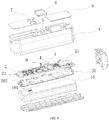
FIG. 1 is an exploded view of a gimbal handle according to an example embodiment of the present disclosure. -
FIG. 2 is a partial enlarged view ofFIG. 1 . -
FIG. 3 is an exploded view of a gimbal handle from a different angle according to an example embodiment of the present disclosure. -
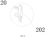
FIG. 4 is a partial enlarged view ofFIG. 3 . -
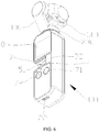
FIG. 5 is a perspective view of a gimbal according to an example embodiment of the present disclosure. -
FIG. 6 is a perspective view of a gimbal from a different angle according to an example embodiment of the present disclosure. -
- 100:
- arm
- 200:
- electric motor
- 300:
- photographing device
- 400:
- gimbal handle
- 1:
- enclosure
- 11:
- front part
- 12:
- rear part
- 13:
- top cover
- 131:
- wiring hole
- 2:
- main control board
- 3:
- electrical contact member
- 4:
- connection member
- 5:
- slot
- 51:
- opening
- 52:
- limit member
- 6:
- cover plate
- 7:
- controller
- 71:
- shutter button
- 72:
- power button
- 8:
- display screen
- 9:
- indicator
- 10:
- power supply battery
- 101:
- plug-in member
- 20:
- heat sink
- 201:
- avoidance slot
- 202:
- heat conduction member
- 30:
- card slot
- Embodiments of the present disclosure are described in detail below with reference to the accompanying drawings. It will be appreciated that the described embodiments are some rather than all of the embodiments of the present disclosure. Other embodiments obtained by those having ordinary skills in the art on the basis of the described embodiments without inventive efforts should fall within the scope of the present disclosure.
- The gimbal handle and the gimbal thereof consistent with the present disclosure will be described in detail below with reference to the accompanying drawings. In the case of no conflict, the following embodiments and features in the implementation can be combined with each other.
-
FIG. 1 is an exploded view of agimbal handle 400 according to an example embodiment of the present disclosure. Embodiment One of the present disclosure provides thegimbal handle 400, which includes anenclosure 1, amain control board 2, and anelectrical contact member 3. Theenclosure 1 includes an accommodation space (not shown). Themain control board 2 is accommodated inside the accommodation space. Theelectrical contact member 3 is provided at themain control board 2, and theelectrical contact member 3 is electrically connected to themain control board 2. Theelectrical contact member 3 penetrates theenclosure 1 and is exposed to the outside of theenclosure 1. Theelectrical contact member 3 can be used to be electrically connected to an external adapter. The external adapter of the embodiment is used to be connected to the terminal, thereby establishing a communication connection between the gimbal and the terminal. In the embodiments of the present disclosure, being provided at theenclosure 1, theelectrical contact member 3 is able to be electrically connected to the external adapter. The communication connection between the gimbal and the terminal (mainly referring to mobile terminal such as a smart phone) can be realized via a simple structure. The connection is established conveniently and quickly without cumbersome entanglement of peripheral wires, and the resulting product looks aesthetically appealing. - The electrical connection between the
electrical contact member 3 and themain control board 2 may be achieved by an existing manner. For example, themain control board 2 may include a main control chip (MCU), a peripheral driving circuit provided adjacent to the MCU, and a connector terminal electrically connected to the MCU. Theelectrical contact member 3 is directly electrically connected to the connector terminal. Alternatively, theelectrical contact member 3 is electrically connected to the connector terminal through wires. - In one embodiment, the
main control board 2 includes a detection circuit. Theelectrical contact member 3 may include a firstelectrical contact member 3 and a secondelectrical contact member 3. The firstelectrical contact member 3 is able to be electrically connected to the adapter. The secondelectrical contact member 3 is connected to the detection circuit. In the embodiment, when the firstelectrical contact member 3 is electrically connected to the adapter, the detection circuit detects a conduction signal. In one feasible implementation example, the conduction signal is a high-level signal. The firstelectrical contact member 3 and the secondelectrical contact member 3 are electrically connected. The detection circuit includes a resistor connected to the ground. One end of the resistor away from the ground is connected to the secondelectrical contact member 3. One end of the secondelectrical contact member 3 away from the resistor is connected to the firstelectrical contact member 3, and becomes an output terminal of the detection circuit. When the firstelectrical contact member 3 is electrically connected to the adapter, because the adapter outputs +5V to pull up the voltages at both ends of the resistor, the detection circuit outputs the high-level signal. - The type of the
electrical contact member 3 may be selected as required. For example, theelectrical contact member 3 may be selected to include retractable pins, an electrical connector interface, or an electrical contact. In the embodiment, theelectrical contact member 3 include the retractable pins. The retractable pins may be stably connected to the external adapter to improve the stability of the communication. Optionally, referring toFIG. 2 , the retractable pins include eight pins. Four pins are arranged in an array to form the firstelectrical contact member 3 and another four pins are arranged in another array to form the secondelectrical contact member 3. It should be understood that, in other embodiments, the number of retractable pins, the pin arrangement, and the function may be configured as required. - Referring to
FIG. 1 andFIG. 2 , the gimbal handle 400 also includes aconnection member 4 provided at themain control board 2. Theconnection member 4 penetrates theenclosure 1 and is exposed to the outside of theenclosure 1. Theconnection member 4 may be detachably connected to the adapter to fix the adapter to theenclosure 1. Thus, the terminal is fixed to theenclosure 1. Theenclosure 1 may function as a base of the terminal. When the gimbal is used for photographing, a user may view the images photographed by the gimbal through the terminal. - The
connection member 4 may include an elastic connection member, a clamping connection member, or other types of connection members. In the embodiment, theconnection member 4 includes the elastic connection member. The elastic connection member and the external adapter are plug-in fitted. The external adapter can be conveniently fixed to theenclosure 1. - Further, the
electrical contact member 3 of the embodiments of the present disclosure may include multiple electrical contact members. Optionally, one part of the multipleelectrical contact members 3 may have a function different from another part of the multipleelectrical contact members 3. For example, in the above embodiments, the firstelectrical contact member 3 and the secondelectrical contact member 3 have different functions. Optionally, the multipleelectrical contact members 3 have the same function. In the embodiment, the multipleelectrical contact members 3 are distributed around theconnection member 4. For example, based on the functions of theelectrical contact members 3, the multipleelectrical contact members 3 are arranged around theconnection member 4. For example, in the embodiment, theelectrical contact members 3 include the firstelectrical contact member 3 and the secondelectrical contact member 3. The firstelectrical contact member 3 and the secondelectrical contact member 3 are arranged on two opposite sides of theconnection member 4. - In addition, referring to
FIG. 1 ,FIG. 5 , andFIG. 6 , aslot 5 is provided at an outer surface of theenclosure 1. Theelectrical contact member 3 and theconnection member 4 are both inserted in and accommodated inside theslot 5. Theslot 5 is used to be detachably connected to the external adapter. The external adapter may be fixed further through theslot 5, such that the external adapter may be more securely fixed to theenclosure 1. - Specifically, referring to
FIG. 6 , theslot 5 includes anopening 51 and alimit member 52 provided opposite to theopening 51. The external adapter moves from theopening 51 to thelimit member 52 to be electrically connected to theelectrical contact member 3 and fixedly connect to theconnection member 4. Thelimit member 52 is used to limit a movement of the external adapter relative to theslot 5. In the embodiment, after the external adapter is inserted in theslot 5 from theopening 51, the external adapter slides along both sides of theslot 5 to move to thelimit member 52. It should be understood that the present disclosure does not specifically limit the opening direction of theopening 51. Theopening 51 may open toward the left r toward the right. In this case, the "left" and "right" are based on the surface of theenclosure 1 where theslot 5 is located as the front side, and the end of theenclosure 1 connecting to the gimbal as the "up". - In the embodiment, referring to
FIG. 5 andFIG. 6 , the four retractable pins adjacent to thelimit member 52 form the firstelectrical contact member 3, and the other four retractable pins away from thelimit member 52 form the secondelectrical contact member 3. The external adapter includes a first end and a second end connected to the terminal. Moreover, the end of the external adapter adjacent to the first end is provided with a thirdelectrical contact member 3. When in use, after the first end of the external adapter is inserted in theslot 5 from theopening 51, the external adapter slides along both sides of theslot 5 and moves to thelimit member 52, such that the thirdelectrical contact member 3 is electrically connected to the firstelectrical contact member 3. Further, the second end protrudes from theenclosure 1 to facilitate the connection to the terminal. While not in use, the external adapter may be accommodated inside theslot 5. The first end is aligned with theopening 51, such that the thirdelectrical contact member 3 is connected (mechanically connected) to the second electrical contact member. The second end is matched with thelimit member 52. - With further reference to
FIG. 1 andFIG. 3 , the gimbal handle 400 also includes acover plate 6. Thecover plate 6 is used to cover theslot 5. When not in use, thecover plate 6 covers theslot 5 to prevent dust and moisture, etc. from entering theelectrical contact member 3 to cause damage to theelectrical contact member 3. When in use, thecover plate 6 opens. Optionally, thecover plate 6 is detachably connected to theenclosure 1. When in use, the cover plate and theenclosure 1 may be separated. Optionally, thecover plate 6 may be rotatably connected to theenclosure 1. Rotating thecover plate 6 makes thecover plate 6 open and close. When thecover plate 6 is not in use, thecover plate 6 is also connected to theenclosure 1, thereby avoiding being lost. - Referring to
FIG. 1 , the gimbal handle 400 also includes adisplay screen 8 provided at theenclosure 1. Themain control board 2 includes a display driving circuit. The display driving circuit is electrically connected to thedisplay screen 8. The images photographed by the gimbal may be viewed directly on thedisplay screen 8. It is not only convenient and quick, but also satisfies diverse needs of users. Thedisplay screen 8 may be anLCD display screen 8 or adisplay screen 8 of another type. - In one embodiment, the
enclosure 1 includes a top part for connecting to agimbal arm 100 or a gimbalelectric motor 200, a bottom part provided opposite to the top part, and a front part (i.e., the front side of the enclosure 1) provided between the top part and the bottom part. - The
electrical contact member 3, theconnection member 4, and thedisplay screen 8 are located at the front part to facilitate user operations. Moreover, thedisplay screen 8 is provided adjacent to the top part. Theelectrical contact member 3 and theconnection member 4 both are located at a side of thedisplay screen 8 away from the top part. Theelectrical contact member 3, theconnection member 4, and thedisplay screen 8 are configured to match user habits. - Further, with reference to
FIG. 1 andFIG. 5 , the gimbal handle 400 also includes acontroller 7 provided at theenclosure 1. Thecontroller 7 is electrically connected to themain control board 2. In one embodiment, operating thecontroller 7 is able to control operations of the gimbal, such as controlling turn-on and turn-off of the gimbal, and controlling photographing of the gimbal camera, etc. Thecontroller 7 may be a button (a virtual button or a physical button) or a knob. Referring toFIG. 6 , thecontroller 7 may include ashutter button 71, apower button 72, and other control buttons, such as anelectric motor 200 rotation control button, an image saving button, and an image playback control button, etc. - The
controller 7 is also located at the front part. Thecontroller 7 is provided adjacent to the bottom part. In one embodiment, with reference toFIG. 5 andFIG. 6 , theelectrical contact member 3 and theconnection member 4 are located between thedisplay screen 8 and thecontroller 7. That is, theelectrical contact member 3 and theconnection member 4 are located at a side of thecontroller 7 away from the bottom part. - In one embodiment, the side of the front of the
enclosure 1 adjacent to the bottom part (specifically, an area between the bottom of theenclosure 1 and the slot 5) is selected to be made of a soft material, such as silica gel. When in use, the soft material makes the touch feel more comfortable, thereby improving user experience. - In addition, in one embodiment, the
enclosure 1 also includes a side part. The gimbal handle 400 also includes acard slot 30 provided at the side part. Thecard slot 30 is electrically connected to themain control board 2. Inserting an SD card in thecard slot 30 allows the images photographed by the gimbal to be stored in the SD card. Moreover, thecard slot 30 is provided at the side without interfering the use of other functions. Thus, the user experience is desirable. - The
enclosure 1 of the embodiments of the present disclosure may be assembled from multiple parts or may be an integral structure. For example, in one embodiment, theenclosure 1 includes afront part 11 and a rear part 12 coupled with thefront part 11, and thefront part 11 and the rear part 12 encloses to form the accommodation space. In another embodiment, theenclosure 1 includes a top part and a bottom part coupled with the top part, and top part and the bottom part enclose to form the accommodation space. For illustration purpose, in one embodiment, theenclosure 1 includes thefront part 11 and the rear part 12. In this embodiment, the front part 11 (i.e., the front part) and the rear part 12 may be detachably connected with each other. Moreover, a sealed structure may be provided at the junction of thefront part 11 and the rear part 12 to prevent external debris from entering the accommodation space. - In one embodiment, the
enclosure 1 may be used as a handheld member or may be mounted at a movable platform. - Further, the
enclosure 1 also includes a top cover 13 (i.e., the top part) provided at the same side as thefront part 11 and the rear part 12. Thetop cover 13 is used for thegimbal arm 100 or the gimbalelectric motor 200 to be mounted thereto. - The
top cover 13 is provided with awiring hole 131. The wires drawn from themain control board 2 pass through thewiring hole 131 to be connected to the gimbalelectric motor 200, such that themain control board 2 controls the rotation of the gimbalelectric motor 200. In addition, after passing through thewiring hole 131, the wires drawn from themain control board 2 may also connect to a photographingdevice 300 mounted at thegimbal arm 100 to obtain and save the images photographed by the photographingdevice 300. After themain control board 2 obtains the images, the images may be played directly on thedisplay screen 8 or may be transmitted to the terminal through the external adapter, and the terminal may play and/or save the images. In addition, themain control board 2 may transmit the images to the SD card for storage. - Further, with reference to
FIG. 1 andFIG. 3 , the gimbal handle 400 also includes apower supply battery 10 accommodated in the accommodation space. Thepower supply battery 10 is used to supply power to themain control board 2. In one embodiment, thepower supply battery 10 is provided between themain control board 2 and the rear part 12, such that theelectrical contact member 3 and theconnection member 4 are exposed through thefront part 11. - Referring to
FIG. 3 , a fixing member is provided at the periphery of the rear part 12. A side of the fixing member facing toward the accommodation space is fixedly connected to thepower supply battery 10. Fixing the power supply battery by the fixing member prevents thepower supply battery 10 from shaking inside the accommodation space. Moreover, the fixing member that fixes thefront part 11 is selected to fix thepower supply battery 10 so that no additional fixing structure is needed to fix thepower supply battery 10 to the rear part 12 and the weight of thegimbal handle 400 is reduced. In one feasible implementation, the fixing member is a clamping member. The clamping member faces toward the accommodation space and clamps thepower supply battery 10. The clamping member clamps thefront part 11 on the side away from the accommodation space. As such, both thepower supply battery 10 and thefront part 11 are fixed to the rear part 12 through the clamping member. It should be understood that the type of the fixing member is not limited by the present disclosure. - The
power supply battery 10 in the embodiment is a rechargeable battery. The rechargeable battery has a large capacity and a small size, thereby facilitating the miniaturization design of thegimbal handle 400. - With reference to
FIG. 1 through FIG. 6 , themain control board 2 also includes a charging interface. The charging interface is exposed at the bottom part, and the charging interface is electrically connected to thepower supply battery 10. Thepower supply battery 10 may be connected to an external power supply through the charging interface, such that thepower supply battery 10 is recharged. - Referring back to
FIG. 1 , the gimbal handle 400 also includes aheat sink 20 accommodated inside the accommodation space. Theheat sink 20 is provided between themain control board 2 and thepower supply battery 10, and theheat sink 20 directly contacts theenclosure 1. In one embodiment, one side of theheat sink 20 contacts electronic components on themain control board 2, and another side of theheat sink 20 contacts thepower supply battery 10, such that the heat generated by the electronic components on themain control board 2 and thepower supply battery 10 in operation is conducted to the outside of theenclosure 1. Thus, the heat dissipation is highly efficient. - In one embodiment, the
heat sink 20 dissipates the heat generated by themain control board 2 and the power supply battery through heat conduction to the outside of theenclosure 1. Specifically, in one embodiment, theheat sink 20 includes aheat conduction member 202. Theheat conduction member 202 contacts thetop cover 13 to dissipate the heat from the inside of the accommodation space to the outside of the accommodation space through thetop cover 13. Theheat conduction member 202 is coupled with thetop cover 13 to improve the heat dissipation efficiency. - The
heat sink 20 extends in a same direction as thepower supply battery 10 extends to maximize the contact area between theheat sink 20 and thepower supply battery 10. As such, most heat generated by thepower supply battery 10 is conducted to theheat conduction member 202, and further to the outside through thetop cover 13. Further, theheat conduction member 202 is disposed at an end of theheat sink 20 and bends while extending. Theheat conduction member 202 bends while extending to increase a heat dissipation area of theheat conduction member 202 and further improve the heat dissipation efficiency. In one embodiment, theheat sink 20 and theheat conduction member 202 may be integrally formed. Theheat sink 20 and theheat conduction member 202 may be made of a same heat conducting material. The embodiments of the present disclosure do not specifically limit the heat conducting material, and any existing type of heat conducting material may be selected. - In one feasible implementation, the
heat sink 20 is a heat equalizing plate. Theheat conduction member 202 thereof is in the shape of a sheet. A surface of the sheet-shapedheat conduction member 202 contacts thetop cover 13 to conduct the heat absorbed by theheat sink 20 to the outside of theenclosure 1. In one embodiment, the sheet-shapedheat conduction member 202 connects to the end of theheat sink 20. - To fix the
heat sink 20 and thepower supply battery 10, referring toFIG. 1 , the power supply battery consistent with the embodiments of the present disclosure includes a plug-inmember 101. Theheat sink 20 includes an avoidance slot 201. Themain control board 2 includes a mounting member. The plug-inmember 101 passes through the avoidance slot 201 to be fixedly connected to the mounting member. As such, through the coupling of the plug-inmember 101 and the mounting member, thepower supply battery 10, theheat sink 20, and themain control board 2 are connected to become one whole piece. Through the fixing member on the rear part 12, thepower supply battery 10 is fixed. Eventually, thepower supply battery 10, theheat sink 20, and themain control board 2 all are fixed to the rear part 12, thereby preventing thepower supply battery 10, theheat sink 20, and themain control board 2 from shaking inside the accommodation space. The plug-inmember 101 and the mounting member may be fixedly connected by any existing connection method, such as snap connection and threaded connection, etc. It should be understood that theheat sink 20 and thepower supply battery 10 may be fixedly connected in a manner other than the coupling of the plug-inmember 101, the avoidance slot 201, and the mounting member described in the embodiment. Other methods of fixedly connecting theheat sink 20 and thepower supply battery 10 together should be within the scope of present disclosure. - Referring back to
FIG. 1 , the gimbal handle 400 also includes anindicator 9 electrically connected to themain control board 2. Theindicator 9 is used to indicate an operation status of themain control board 2. Theindicator 9 may include one or more indicators. In one embodiment, theindicator 9 includes one indicator. Themain control board 2, the gimbalelectric motor 200 and the photographingdevice 300 mounted at the gimbal handle 400 all are powered by thepower supply battery 10. - Specifically, after the
power supply battery 10 supplies power to themain control board 2, the gimbalelectric motor 200 and the photographingdevice 300 mounted at thegimbal handle 400, but before the gimbalelectric motor 200 and the photographingdevice 300 mounted at the gimbal handle 400 become operational, theindicator 9 turns on steadily. After thepower supply battery 10 supplies power to themain control board 2, the gimbalelectric motor 200 and the photographingdevice 300 mounted at thegimbal handle 400, and the gimbalelectric motor 200 and the photographingdevice 300 mounted at the gimbal handle 400 become operational, theindicator 9 blinks. When thepower supply battery 10 does not supply the power, theindicator 9 turns off. Of course, the display mode of theindicator 9 is not limited to the above description, and specifically, the display mode of theindicator 9 may be configured as required. - With reference to
FIG. 5 andFIG. 6 , Embodiment One of the present disclosure also provides a gimbal, including anarm 100, anelectric motor 200 for driving thearm 100 to rotate, a photographingdevice 300 mounted at thearm 100, an adapter (not shown) for connecting to a terminal, and agimbal handle 400. The structure, function, and operational principle and effect of the gimbal handle 400 may be referred to the description of the gimbal handle in Embodiment One, and will not repeated herein. - The
arm 100 or theelectric motor 200 may be fixed to theenclosure 1. For example, in one embodiment, the housing of theelectric motor 200 may be connected to theenclosure 1 through a quick release structure. In some embodiments, the gimbal is a three-axis gimbal. Thearm 100 may include a pitch-axis arm, a roll-axis arm, or a yaw-axis arm. Theelectric motor 200 may include a pitch-axis electric motor, a roll-axis electric motor, or a yaw-axis electric motor, configured to drive thecorresponding arm 100 to rotate. In other embodiments, the gimbal may also be a two-axis gimbal or a four-axis gimbal, etc. - The adapter is electrically connected to the
electrical contact member 3 of thegimbal handle 400. Specific implementation may be referred to the description in Embodiment One, and will not be repeated herein. The adapter and the terminal may be electrically connected in a plug-in manner or may be electrically connected in other manners. Optionally, the terminal may be rotatably connected to the adapter to adjust an angle of the terminal relative to the gimbal handle, thereby satisfying user's need for certain viewing angles. It should be noted that, in the embodiments of the present disclosure, the adapter is not in the form of a wire, but may be used as a fixing member to fix the terminal to thegimbal handle 400. - In addition, in one embodiment, the photographing
device 300 may be a camera or a photographing element composed of a lens and an image sensor (e.g., a CMOS or CCD sensor), etc., which may be specifically selected as required. - Referring to
FIG. 1 andFIG. 3 , Embodiment Two provides anothergimbal handle 400. The gimbal handle 400 includes anenclosure 1, amain control board 2, apower supply battery 10, and aheat sink 20. Theenclosure 1 includes an accommodation space. Themain control board 2, thepower supply battery 10, and theheat sink 20 all are accommodated in the accommodation space. Thepower supply battery 10 is used to supply power to themain control board 2. Theheat sink 20 is provided between themain control board 2 and thepower supply battery 10. Moreover, one end of theheat sink 20 contacts theenclosure 1 to conduct the heat from the inside of the accommodation space to the outside of the accommodation space through theenclosure 1. - The
enclosure 1 consistent with the embodiments of the present disclosure may be assembled from several parts or may be an integral structure. For example, in one embodiment, theenclosure 1 includes afront part 11 and a rear part 12 coupled with thefront part 11, and thefront part 11 and the rear part 12 enclose to form an accommodation space. In another embodiment, theenclosure 1 includes a top part and a bottom part coupled with the top part, and the top part and the bottom part enclose to form an accommodation space. For illustration purpose, in the embodiments of the present disclosure, theenclosure 1 includes the front part 11 (i.e., the front part) and the rear part 12. In one embodiment, thefront part 11 and the rear part 12 may be detachably connected with each other. Moreover, a sealed structure may be provided at the junction of thefront part 11 and the rear part 12 to prevent external debris from entering the accommodation space. - In one embodiment, the
enclosure 1 may be used as a handheld member or may be mounted at a movable platform. - Further, the
enclosure 1 also includes a top cover 13 (i.e., the top) provided at the same side as thefront part 11 and the rear part 12. Thetop cover 13 is used for thegimbal arm 100 or the gimbalelectric motor 200 to be mounted thereto. - The
top cover 13 is provided with awiring hole 131. The wires drawn from themain control board 2 pass through thewiring hole 131 to be connected to the gimbalelectric motor 200, such that themain control board 2 controls the rotation of the gimbalelectric motor 200. In addition, after passing through thewiring hole 131, the wires drawn from themain control board 2 may also connect to a photographingdevice 300 mounted at thegimbal arm 100 to obtain and save the images photographed by the photographingdevice 300. After themain control board 2 obtains the images, the images may be played directly on thedisplay screen 8 or may be transmitted to the terminal through the external adapter, and the terminal may play and/or save the images. In addition, themain control board 2 may transmit the images to the SD card for storage. - Further, with reference to
FIG. 1 andFIG. 3 , the gimbal handle 400 also includes apower supply battery 10 accommodated in the accommodation space. Thepower supply battery 10 is used to supply power to themain control board 2. In one embodiment, thepower supply battery 10 is provided between themain control board 2 and the rear part 12, such that theelectrical contact member 3 and theconnection member 4 are exposed through thefront part 11. - Referring to
FIG. 3 , a fixing member is provided at the periphery of the rear part 12. The fixing member faces toward the accommodation space and is fixedly connected to thepower supply battery 10. Fixing the power supply battery by the fixing member prevents thepower supply battery 10 from shaking inside the accommodation space. Moreover, the fixing member that fixes thefront part 11 is selected to fix thepower supply battery 10 so that no additional fixing structure is needed to fix thepower supply battery 10 to the rear part 12 and the weight of thegimbal handle 400 is reduced. In one feasible implementation, the fixing member is a clamping member. The clamping member faces toward the accommodation space and clamps thepower supply battery 10. The clamping member clamps thefront part 11 on the side away from the accommodation space. As such, both thepower supply battery 10 and thefront part 11 are fixed to the rear part 12 through the clamping member. It should be understood that the type of the fixing member is not limited by the present disclosure. - The
power supply battery 10 in the embodiment is a rechargeable battery. The rechargeable battery has a large capacity and a small size, thereby facilitating the miniaturization design of thegimbal handle 400. - With reference to
FIG. 1 through FIG. 6 , themain control board 2 also includes a charging interface. The charging interface is exposed at the bottom part, and the charging interface is electrically connected to thepower supply battery 10. Thepower supply battery 10 may be connected to an external power supply through the charging interface, such that thepower supply battery 10 is recharged. - Referring back to
FIG. 1 , the gimbal handle 400 also includes aheat sink 20 accommodated inside the accommodation space. Theheat sink 20 is provided between themain control board 2 and thepower supply battery 10, and theheat sink 20 directly contacts theenclosure 1. In one embodiment, one side of theheat sink 20 contacts electronic components on themain control board 2, and another side of theheat sink 20 contacts thepower supply battery 10, such that the heat generated by the electronic components on themain control board 2 and thepower supply battery 10 in operation is conducted to the outside of theenclosure 1. Thus, the heat dissipation is highly efficient. - In one embodiment, the
heat sink 20 dissipates the heat generated by themain control board 2 and thepower supply battery 10 through heat conduction to the outside of theenclosure 1. Specifically, in one embodiment, theheat sink 20 includes aheat conduction member 202. Theheat conduction member 202 contacts thetop cover 13 to dissipate the heat from the inside of the accommodation space to the outside of the accommodation space through thetop cover 13. Theheat conduction member 202 is coupled with thetop cover 13 to improve the heat dissipation efficiency. - The
heat sink 20 extends in a same direction as thepower supply battery 10 extends to maximize the contact area between theheat sink 20 and thepower supply battery 10. As such, most heat generated by thepower supply battery 10 is conducted to theheat conduction member 202, and further to the outside through thetop cover 13. Further, theheat conduction member 202 is disposed at the end of theheat sink 20 and bends while extending. Theheat conduction member 202 bends while extending to increase a heat dissipation area of theheat conduction member 202 and further improve the heat dissipation efficiency. In one embodiment, theheat sink 20 and theheat conduction member 202 may be integrally formed. Theheat sink 20 and theheat conduction member 202 may be made of a same heat conducting material. The embodiments of the present disclosure do not specifically limit the heat conducting material, and any existing type of heat conducting material may be selected. - In one feasible implementation, the
heat sink 20 is a heat equalizing plate. Theheat conduction member 202 thereof is in the shape of a sheet. The sheet-shapedheat conduction member 202 contacts thetop cover 13 to conduct the heat absorbed by theheat sink 20 to the outside of theenclosure 1. In one embodiment, the sheet-shapedheat conduction member 202 connects to the end of theheat sink 20. - To fix the
heat sink 20 and thepower supply battery 10, referring toFIG. 1 , thepower supply battery 10 consistent with the embodiments of the present disclosure includes a plug-inmember 101. Theheat sink 20 includes an avoidance slot 201. Themain control board 2 includes a mounting member. The plug-inmember 101 passes through the avoidance slot 201 to be fixedly connected to the mounting member. As such, through the coupling of the plug-inmember 101 and the mounting member, thepower supply battery 10, theheat sink 20, and themain control board 2 are connected to become one whole piece. Through the fixing member on the rear part 12, thepower supply battery 10 is fixed. Eventually, thepower supply battery 10, theheat sink 20, and themain control board 2 all are fixed to the rear part 12, thereby preventing thepower supply battery 10, theheat sink 20, and themain control board 2 from shaking inside the accommodation space. The plug-inmember 101 and the mounting member may be fixedly connected by any existing connection method, such as snap connection and threaded connection, etc. It should be understood that theheat sink 20 and thepower supply battery 10 may be fixedly connected in a manner other than the coupling of the plug-inmember 101, the avoidance slot 201, and the mounting member described in the embodiment. Other methods of fixedly connecting theheat sink 20 and thepower supply battery 10 together should be within the scope of the present disclosure. - Other parts of the gimbal handle 400 may be referred to the description in Embodiment One, and will not repeated herein.
- With reference to
FIG. 5 andFIG. 6 , Embodiment Two of the present disclosure also provides a gimbal, including anarm 100, anelectric motor 200 for driving thearm 100 to rotate, a photographingdevice 300 mounted at thearm 100, and agimbal handle 400. The structure, function, and operational principle and effect of the gimbal handle 400 may be referred to the description of the gimbal handle in Embodiment Two, and will not repeated herein. - The
arm 100 or theelectric motor 200 may be fixed to theenclosure 1. For example, in one embodiment, the housing of theelectric motor 200 may be connected to theenclosure 1 through a quick release structure. In some embodiments, the gimbal is a three-axis gimbal. Thearm 100 may include a pitch-axis arm, a roll-axis arm, or a yaw-axis arm. Theelectric motor 200 may include a pitch-axis electric motor, a roll-axis electric motor, or a yaw-axis electric motor, configured to drive thecorresponding arm 100 to rotate. In some other embodiments, the gimbal may also be a two-axis gimbal or a four-axis gimbal, etc. - In addition, in one embodiment, the photographing
device 300 may be a camera or a photographing element composed of a lens and an image sensor (e.g., a CMOS or CCD sensor), etc., which may be specifically selected as required. - In the description of the present disclosure, "top," "bottom," "front," "rear," "left," and "right" should be understood as sequentially assembling the photographing
device 300, thearm 100, and the gimbal handle 400 from top to bottom to form the directions of "top," "bottom," "front," "rear," "left," and "right" of the gimbal. - It should be understood that, in this specification, relational terms such as first and second are only used to distinguish one entity or operation from another entity or operation, and do not necessarily require or imply existence of the actual relationship or sequence among these entities or operations. The terms "include," "compose," or any other variants thereof are intended to cover non-exclusive inclusion, so that a process, a method, an article, or a device including a series of elements not only includes these elements, but also includes other elements not explicitly listed, or further includes elements inherent to the process, the method, the article, or the device. In absence of further restrictions, the element defined by the sentence "including a .. " does not exclude the existence of other same elements in the process, the method, the article, or the device that includes the element.
- The gimbal handle and the gimbal thereof provided by the embodiments of the present disclosure are described in detail. In the specification, specific examples are used to explain the principles and implementations of the present disclosure. The description of the embodiments is intended to assist comprehension of the methods and core inventive ideas of the present disclosure. At the same time, those of ordinary skill in the art may change or modify the specific implementation and the scope of the application according to the inventive ideas of the present disclosure. Thus, the content of the specification should not be construed as limiting the present disclosure.
Claims (74)
- A gimbal handle, comprising:an enclosure including an accommodation space;a main control board accommodated in the accommodation space; andan electrical contact member provided at the main control board and electrically connected to the main control board,wherein the electrical contact member penetrates the enclosure to expose to an outside of the enclosure, and is able to be electrically connected to an external adapter.
- The gimbal handle according to claim 1, wherein:the main control board includes a detection circuit;the electrical contact member includes a first electrical contact member and a second electrical contact member, wherein the first electrical contact member is able to be electrically connected to the adapter and the second electrical contact member is connected to the detection circuit;when the first electrical contact is electrically connected to the adapter, the detection circuit detects a conduction signal.
- The gimbal handle according to claim 1, wherein:
the electrical contact member includes retractable pins. - The gimbal handle according to claim 1, further comprising:
a connection member provided at the main control board, wherein the connection member penetrates the enclosure to expose to the outside of the enclosure, and is detachably connected to the adapter. - The gimbal handle according to claim 4, wherein:
the electrical contact member includes a plurality of electrical contact members distributed around the connection member. - The gimbal handle according to claim 4, wherein:
the connection member includes an elastic connection member, wherein the elastic connection member and the external adapter are plug-in fitted. - The gimbal handle according to claim 4, wherein:an external surface of the enclosure is provided with a slot, wherein the electrical contact member and the connection member are both inserted in and accommodated inside the slot;the slot is used to be detachably connected to the external adapter.
- The gimbal handle according to claim 7, wherein:the slot includes an opening and a limit member provided opposite to the opening;the external adapter moves from the opening to the limit member to be electrically connected to the electrical contact member and to be fixedly connected to the connection member, wherein the limit member is used to limit a movement of the external adapter relative to the slot.
- The gimbal handle according to claim 7, further comprising:
a cover plate used to cover the slot. - The gimbal handle according to claim 1, further comprising:
a display screen provided at the enclosure, wherein the main control board includes a display driving circuit, and the display driving circuit is electrically connected to the display screen. - The gimbal handle according to claim 10, wherein:the enclosure includes a top part for connecting to a gimbal arm or a gimbal electric motor, a bottom part provided opposite to the top part, and a front part provided between the top part and the bottom part;the electrical contact member, the connection member, and the display screen are located at the front part, the display screen is provided adjacent to the top part, and the electrical contact member and the connection member both are located at a side of the display screen away from the top part.
- The gimbal handle according to claim 1, further comprising:
a controller provided at the enclosure, wherein the controller is electrically connected to the main control board. - The gimbal handle according to claim 12, wherein:the enclosure includes a top part for connecting to a gimbal arm or a gimbal electric motor, a bottom part provided opposite to the top part, and a front part provided between the top part and the bottom part;the electrical contact member and the connection member are located at the front part, the display screen is provided adjacent to the top part, and the electrical contact member and the connection member both are located at a side of the controller away from the bottom part.
- The gimbal handle according to claim 12, wherein:
the controller includes a power button and a shutter button. - The gimbal handle according to claim 1, wherein:
the enclosure also includes a side part, the gimbal handle also includes a card slot provided at the side part, the card slot is electrically connected to the main control board. - The gimbal handle according to claim 1, further comprising:a power supply battery accommodated in the accommodation space,wherein:the power supply battery is used to supply power to the main control board;the enclosure includes a front enclosure and a rear enclosure coupled with the front enclosure, the front enclosure and the rear enclosure enclose to form the accommodation space;the power supply battery is provided between the main control board and the rear enclosure.
- The gimbal handle according to claim 16, wherein:a fixing member is provided at the periphery of the rear enclosure;a side of the fixing member facing toward the accommodation space is fixedly connected to the power supply battery;another side of the fixing member away from the accommodation space is fixedly connected to the front enclosure.
- The gimbal handle according to claim 17, wherein:
the fixing member is a clamping member. - The gimbal handle according to claim 16, wherein:the enclosure includes a top part for connecting to the gimbal and a bottom part provided opposite to the top part;the main control board also includes a charging interface, the charging interface is exposed at the bottom part, and the charging interface is electrically connected to the power supply battery.
- The gimbal handle according to claim 16, further comprising:
a heat sink accommodated in the accommodation space, wherein the heat sink is provided between the main control board and the power supply battery. - The gimbal handle according to claim 20, wherein:the power supply battery includes a plug-in member;the heat sink includes an avoidance slot;the main control board includes a mounting member;the plug-in member passes through the avoidance slot to be fixedly connected to the mounting member.
- The gimbal handle according to claim 20, wherein:the heat sink includes a heat conduction member;the enclosure also includes a top cover provided at a same side as a front part and a rear part, the top cover is used for a gimbal arm or a gimbal electric motor to be mounted thereto;the heat conduction member contacts the top cover to dissipate heat from inside of the accommodation space to outside of the accommodation space through the top cover.
- The gimbal handle according to claim 22, wherein:the heat sink extends in a same direction as the power supply battery extends;the heat conduction member is disposed at an end of the heat sink and bends while extending.
- The gimbal handle according to claim 22, wherein:the heat sink is a heat equalizing plate;the heat conduction member is in the shape of a sheet;a surface of the sheet-shaped heat conduction member contacts the top cover.
- The gimbal handle according to claim 22, wherein:the top cover is provided with a wiring hole;wires drawn from the main control board pass through the wiring hole to be connected to the gimbal electric motor.
- The gimbal handle according to claim 1, further comprising:an indicator electrically connected to the main control board;the indicator is used to indicate an operation status of the main control board.
- A gimbal, comprising:an arm;an electric motor for driving the arm to rotate;a photographing device mounted at the arm;an adapter for connecting to a terminal; anda gimbal handle, wherein the gimbal handle includes:an enclosure including an accommodation space;a main control board accommodated in the accommodation space; andan electrical contact member provided at the main control board and electrically connected to the main control board,wherein:the electrical contact member penetrates the enclosure to expose to an outside of the enclosure, and is able to be electrically connected to the adapter; andthe arm or the electric motor is fixed to the enclosure, and the adapter is electrically connected to the electrical contact member of the gimbal handle.
- The gimbal according to claim 27, wherein:the main control board includes a detection circuit;the electrical contact member includes a first electrical contact member and a second electrical contact member, wherein the first electrical contact member is able to be electrically connected to the adapter, the second electrical contact member is connected to the detection circuit;when the first electrical contact is electrically connected to the adapter, the detection circuit detects a conduction signal.
- The gimbal according to claim 27, wherein:
the electrical contact member includes retractable pins. - The gimbal according to claim 27, wherein the gimbal handle further includes:
a connection member provided at the main control board, wherein the connection member penetrates the enclosure to expose to the outside of the enclosure, the connection member is able to be detachably connected to the adapter. - The gimbal according to claim 30, wherein:
the electrical contact member includes a plurality of electrical contact members distributed around the connection member. - The gimbal according to claim 30, wherein:
the connection member includes an elastic connection member, wherein the elastic connection member and the external adapter are plug-in fitted. - The gimbal according to claim 30, wherein:an external surface of the enclosure is provided with a slot, wherein the electrical contact member and the connection member are both inserted in and accommodated inside the slot;the slot is used to be detachably connected to the external adapter.
- The gimbal according to claim 33, wherein:the slot includes an opening and a limit member provided opposite to the opening;the external adapter moves from the opening to the limit member to be electrically connected to the electrical contact member and to be fixedly connected to the connection member, wherein the limit member is used to limit a movement of the external adapter relative to the slot.
- The gimbal according to claim 33, wherein the gimbal handle further includes:
a cover plate used to cover the slot. - The gimbal according to claim 27, wherein the gimbal handle further includes:
a display screen provided at the enclosure, wherein the main control board includes a display driving circuit, the display driving circuit is electrically connected to the display screen. - The gimbal according to claim 36, wherein:the enclosure includes a top part for connecting to a gimbal arm or a gimbal electric motor, a bottom part provided opposite to the top part, and a front part provided between the top part and the bottom part;the electrical contact member, the connection member, and the display screen are located at the front part, the display screen is provided adjacent to the top part, and the electrical contact member and the connection member both are located at a side of the display screen away from the top part.
- The gimbal according to claim 27, wherein the gimbal handle further comprises:
a controller provided at the enclosure, wherein the controller is electrically connected to the main control board. - The gimbal according to claim 38, wherein:the enclosure includes a top part for connecting to the gimbal arm or the gimbal electric motor, a bottom part provided opposite to the top part, and a front part provided between the top part and the bottom part;the electrical contact member and the controller are located at the front part, the controller is provided adjacent to the bottom part, the electrical contact member and the connection member both are located at a side of the controller away from the bottom part.
- The gimbal according to claim 38, wherein:
the controller includes a power button and a shutter button. - The gimbal according to claim 27, wherein:
the enclosure also includes a side part, the gimbal handle also includes a card slot provided at the side part, the card slot is electrically connected to the main control board. - The gimbal according to claim 27, wherein the gimbal handle further comprises:a power supply battery accommodated in the accommodation space,wherein:the power supply battery is used to supply power to the main control board;the enclosure includes a front part and a rear part coupled with the front part, and the front part and the rear part enclose to form the accommodation space;the power supply battery is provided between the main control board and the rear part.
- The gimbal according to claim 42, wherein:a fixing member is provided at a periphery of the rear part;a side of the fixing member facing toward the accommodation space is fixedly connected to the power supply battery;another side of the fixing member away from the accommodation space is fixedly connected to the front part.
- The gimbal according to claim 43, wherein:
the fixing member is a clamping member. - The gimbal according to claim 42, wherein:the enclosure includes a top part for connecting to the gimbal and a bottom part provided opposite to the top part;the main control board also includes a charging interface, the charging interface is exposed at the bottom part, and the charging interface is electrically connected to the power supply battery.
- The gimbal according to claim 42, wherein the gimbal handle further comprises:
a heat sink accommodated in the accommodation space, wherein the heat sink is provided between the main control board and the power supply battery. - The gimbal according to claim 46, wherein:the power supply battery includes a plug-in member;the heat sink includes an avoidance slot;the main control board includes a mounting member;the plug-in member passes through the avoidance slot to be fixedly connected to the mounting member.
- The gimbal according to claim 46, wherein:the heat sink includes a heat conduction member;the enclosure also includes a top cover provided at a same side as the front part and the rear part, the top cover is used for a gimbal arm or a gimbal electric motor to be mounted thereto;the heat conduction member contacts the top cover to dissipate heat from inside of the accommodation space to outside of the accommodation space through the top cover.
- The gimbal according to claim 48, wherein:the heat sink extends in a same direction as the power supply battery extends;the heat conduction member is disposed at an end of the heat sink and bends while extending.
- The gimbal according to claim 48, wherein:the heat sink is a heat equalizing plate;the heat conduction member is in the shape of a sheet;a surface of the sheet-shaped heat conduction member contacts the top cover.
- The gimbal according to claim 48, wherein:the top cover is provided with a wiring hole;wires drawn from the main control board pass through the wiring hole to be connected to the gimbal electric motor.
- The gimbal according to claim 27, wherein the gimbal handle further comprises:an indicator electrically connected to the main control board;the indicator is used to indicate an operation status of the main control board.
- The gimbal according to claim 27, wherein:the arm includes a pitch-axis arm, a roll-axis arm, and a yaw-axis arm;the electric motor includes a pitch-axis electric motor, a roll-axis electric motor, and a yaw-axis electric motor.
- A gimbal handle, comprising:an enclosure including an accommodation space;a main control board accommodated in the accommodation space;a power supply battery; anda heat sink,wherein:the main control board, the power supply battery, and the heat sink are accommodated in the accommodation space;the power supply battery is used to supply power to the main control board;the heat sink is provided between the main control board and the power supply battery, and one end of the heat sink contacts the enclosure to conduct heat from inside of the accommodation space to outside of the accommodation space through the enclosure.
- The gimbal handle according to claim 54, wherein:the enclosure includes a front part, a rear part coupled with the front part, and the front part and the rear part enclose to form the accommodation space;the power supply battery is provided between the main control board and the rear part.
- The gimbal handle according to claim 55, wherein:a fixing member is provided at the periphery of the rear part;a side of the fixing member facing toward the accommodation space is fixedly connected to the power supply battery;another side of the fixing member facing away from the accommodation space is fixedly connected to the front part.
- The gimbal handle according to claim 56, wherein:
the fixing member is a clamping member. - The gimbal handle according to claim 55, wherein:the power supply battery includes a plug-in member;the heat sink includes an avoidance slot;the main control board includes a mounting member;the plug-in member passes through the avoidance slot to be fixedly connected to the mounting member.
- The gimbal handle according to claim 58, wherein:the heat sink includes a heat conduction member;the enclosure also includes a top cover provided at a same side as the front part and the rear part, and the top cover is used for a gimbal arm or a gimbal electric motor to be mounted thereto;the heat conduction member contacts the top cover to dissipate the heat from the inside of the accommodation space to the outside of the accommodation space through the top cover.
- The gimbal handle according to claim 59, wherein:the heat sink extends in a same direction as the power supply battery extends;the heat conduction member is disposed at an end of the heat sink and bends while extending.
- The gimbal handle according to claim 59, wherein:the heat sink is a heat equalizing plate;the heat conduction member is in the shape of a sheet;a surface of the sheet-shaped heat conduction member contacts the top cover.
- The gimbal handle according to claim 59, wherein:the top cover is provided with a wiring hole;wires drawn from the main control board pass through the wiring hole to be connected to the gimbal electric motor.
- The gimbal handle according to claim 54, wherein:the enclosure includes a top part for connecting to a gimbal and a bottom part provided opposite to the top part;the main control board also includes a charging interface, the charging interface is exposed at the bottom part, and the charging interface is electrically connected to the power supply battery.
- A gimbal, comprising:an arm;an electric motor for driving the arm to rotate;a photographing device mounted at the arm; anda gimbal handle, wherein the gimbal handle includes:an enclosure including an accommodation space;a main control board;a power supply battery; anda heat sink,wherein:the main control board, the power supply battery, and the heat sink are all accommodated in the accommodation space;the arm or the electric motor is fixed to the enclosure;the power supply battery is used to supply power to the main control board;the heat sink is provided between the main control board and the power supply battery, and one end of the heat sink contacts the enclosure to conduct heat from inside of the accommodation space to outside of the accommodation space through the enclosure.
- The gimbal according to claim 64, wherein:the enclosure includes a front part, a rear part coupled with the front part, and the front part and the rear part enclose to form the accommodation space;the power supply battery is provided between the main control board and the rear part.
- The gimbal according to claim 65, wherein:a fixing member is provided at the periphery of the rear part;a side of the fixing member facing toward the accommodation space is fixedly connected to the power supply battery;another side of the fixing member away from the accommodation space is fixedly connected to the front part.
- The gimbal according to claim 66, wherein:
the fixing member is a clamping member. - The gimbal according to claim 65, wherein:the power supply battery includes a plug-in member;the heat sink includes an avoidance slot;the main control board includes a mounting member;the plug-in member passes through the avoidance slot to be fixedly connected to the mounting member.
- The gimbal according to claim 68, wherein:the heat sink includes a heat conduction member;the enclosure also includes a top cover provided at a same side as the front part and the rear part, and the top cover is used for a gimbal arm or a gimbal electric motor to be mounted thereto;the heat conduction member contacts the top cover to dissipate the heat from the inside of the accommodation space to the outside of the accommodation space through the top cover.
- The gimbal according to claim 69, wherein:the heat sink extends in a same direction as the power supply battery extends;the heat conduction member is disposed at an end of the heat sink and bends while extending.
- The gimbal according to claim 69, wherein:the heat sink is a heat equalizing plate;the heat conduction member is in the shape of a sheet;a surface of the sheet-shaped heat conduction member contacts the top cover.
- The gimbal according to claim 69, wherein:the top cover is provided with a wiring hole;wires drawn from the main control board pass through the wiring hole to be connected to the gimbal electric motor.
- The gimbal according to claim 64, wherein:the enclosure includes a top part for connecting to a gimbal and a bottom part provided opposite to the top part; andthe main control board also includes a charging interface, the charging interface is exposed at the bottom part, and the charging interface is electrically connected to the power supply battery.
- The gimbal according to claim 64, wherein:the arm includes a pitch-axis arm, a roll-axis arm, and a yaw-axis arm;the electric motor includes a pitch-axis electric motor, a roll-axis electric motor, and a yaw-axis electric motor.
Applications Claiming Priority (1)
| Application Number | Priority Date | Filing Date | Title |
|---|---|---|---|
| PCT/CN2018/093846 WO2020000442A1 (en) | 2018-06-29 | 2018-06-29 | Cradle head handle and cradle head provided with same |
Publications (2)
| Publication Number | Publication Date |
|---|---|
| EP3817353A1 true EP3817353A1 (en) | 2021-05-05 |
| EP3817353A4 EP3817353A4 (en) | 2021-06-16 |
Family
ID=68112763
Family Applications (1)
| Application Number | Title | Priority Date | Filing Date |
|---|---|---|---|
| EP18924119.3A Withdrawn EP3817353A4 (en) | 2018-06-29 | 2018-06-29 | FORK HEAD HANDLE AND FORK HEAD HANDLE PROVIDED WITH IT |
Country Status (4)
| Country | Link |
|---|---|
| US (1) | US11537029B2 (en) |
| EP (1) | EP3817353A4 (en) |
| CN (1) | CN110325445B (en) |
| WO (1) | WO2020000442A1 (en) |
Families Citing this family (3)
| Publication number | Priority date | Publication date | Assignee | Title |
|---|---|---|---|---|
| CN117897337A (en) * | 2021-10-20 | 2024-04-16 | 深圳市大疆创新科技有限公司 | Brackets, control devices, pan/tilt systems, shooting components and systems |
| JP1730566S (en) * | 2022-04-15 | 2022-11-24 | Camera controller with pan head | |
| CN114710614B (en) * | 2022-06-06 | 2022-09-09 | 武汉东湖学院 | A solar photovoltaic power generation image data transmission device |
Family Cites Families (19)
| Publication number | Priority date | Publication date | Assignee | Title |
|---|---|---|---|---|
| US9002518B2 (en) * | 2003-06-30 | 2015-04-07 | Intuitive Surgical Operations, Inc. | Maximum torque driving of robotic surgical tools in robotic surgical systems |
| US8142083B2 (en) * | 2008-11-14 | 2012-03-27 | Brown Garrett W | Extendable camera support and stabilization apparatus |
| US8714744B2 (en) * | 2009-10-07 | 2014-05-06 | Nigel J. Greaves | Gimbaled handle stabilizing controller assembly |
| US8585205B2 (en) * | 2009-10-07 | 2013-11-19 | Nigel J. Greaves | Gimbaled handle stabilizing controller assembly |
| EP2499416A4 (en) * | 2009-11-13 | 2016-04-20 | Garrett W Brown | Extendable camera support and stablization apparatus |
| CN201795240U (en) * | 2010-07-17 | 2011-04-13 | 张海翔 | Multifunctional pan-tilt |
| US9575330B2 (en) * | 2011-11-02 | 2017-02-21 | Steven D. Wagner | Actively stabilized payload support apparatus and methods |
| WO2013094460A1 (en) * | 2011-12-19 | 2013-06-27 | オリンパス株式会社 | Method for producing optical fiber, optical fiber, and endoscope |
| US20130259463A1 (en) * | 2012-04-03 | 2013-10-03 | Janusz Dybowski | Camera slider/crane |
| WO2016015232A1 (en) * | 2014-07-29 | 2016-02-04 | SZ DJI Technology Co., Ltd. | Systems and methods for payload stabilization |
| CN105518757B (en) * | 2015-01-06 | 2018-06-12 | 深圳市大疆灵眸科技有限公司 | Holder remote controler and the hand-held holder using the holder remote controler |
| US9458963B1 (en) * | 2015-03-31 | 2016-10-04 | Swiftcam Technologies Group Company Limited | 360-degree gimbal system |
| US10208887B2 (en) * | 2015-04-13 | 2019-02-19 | Yuneec Technology Co., Limited | Gimbal handheld holder |
| US9904149B2 (en) * | 2015-12-31 | 2018-02-27 | Gopro, Inc. | Camera gimbal mount system |
| CN106090579A (en) * | 2016-08-10 | 2016-11-09 | 深圳市固胜智能科技有限公司 | A kind of hand-held device stable equilibrium |
| CN207394316U (en) * | 2017-06-19 | 2018-05-22 | 深圳市大疆创新科技有限公司 | Hand-held holder |
| CN107255901A (en) * | 2017-07-25 | 2017-10-17 | 深圳创客派科技有限公司 | A kind of many inclination angle full length shot stabilizers |
| CN207200802U (en) * | 2017-09-18 | 2018-04-06 | 深圳市大疆创新科技有限公司 | Self-shooting bar, head camera and filming apparatus |
| CN207471091U (en) * | 2017-09-19 | 2018-06-08 | 深圳市大疆创新科技有限公司 | Holder device |
-
2018
- 2018-06-29 WO PCT/CN2018/093846 patent/WO2020000442A1/en not_active Ceased
- 2018-06-29 CN CN201880011480.8A patent/CN110325445B/en active Active
- 2018-06-29 EP EP18924119.3A patent/EP3817353A4/en not_active Withdrawn
-
2020
- 2020-12-17 US US17/125,229 patent/US11537029B2/en active Active
Also Published As
| Publication number | Publication date |
|---|---|
| WO2020000442A1 (en) | 2020-01-02 |
| US11537029B2 (en) | 2022-12-27 |
| US20210103207A1 (en) | 2021-04-08 |
| CN110325445B (en) | 2023-07-11 |
| EP3817353A4 (en) | 2021-06-16 |
| CN110325445A (en) | 2019-10-11 |
Similar Documents
| Publication | Publication Date | Title |
|---|---|---|
| US11537029B2 (en) | Gimbal handle and gimbal having same | |
| US8432124B2 (en) | Portable electronic device carrier with charging system | |
| KR20200121151A (en) | An foldable electronic device including a sliding module and control method | |
| US12242311B2 (en) | Display device | |
| CN103166287B (en) | The base of mobile electronic terminal device | |
| US7420615B2 (en) | Portable electronic device including swivel accessorial module | |
| US20170068272A1 (en) | Laptop computer case with integrated file storage and batteries | |
| CN204376964U (en) | Mobile terminal | |
| US11340717B2 (en) | Processing apparatus and processing system | |
| CN110657338B (en) | Tripod head camera | |
| JP2011182566A (en) | Charging power supply device | |
| CN120321899A (en) | Modular peripheral integrated box and portable electronic device | |
| CN210804185U (en) | Protective housing with electronic function | |
| WO2019014986A1 (en) | Protective housing assembly for electronic device | |
| KR101627460B1 (en) | Rotatable charging system for portable device | |
| WO2017137797A2 (en) | Portable solar charger | |
| TWM431612U (en) | Electronic facility protection cover with charge cable | |
| JP2002247775A (en) | Stand for charging | |
| JP3197452U (en) | Coupling system accessories | |
| JP2006325343A (en) | Ac adaptor and electronic equipment | |
| CN208474836U (en) | Gimbal handle and gimbal with the same | |
| CN212752344U (en) | Be applied to electronic equipment's protective housing subassembly | |
| US6403254B1 (en) | Battery means for hand held electronic devices | |
| TWM541650U (en) | Charging assembly | |
| CN221927519U (en) | Portable mobile hard disk |
Legal Events
| Date | Code | Title | Description |
|---|---|---|---|
| STAA | Information on the status of an ep patent application or granted ep patent |
Free format text: STATUS: THE INTERNATIONAL PUBLICATION HAS BEEN MADE |
|
| PUAI | Public reference made under article 153(3) epc to a published international application that has entered the european phase |
Free format text: ORIGINAL CODE: 0009012 |
|
| STAA | Information on the status of an ep patent application or granted ep patent |
Free format text: STATUS: REQUEST FOR EXAMINATION WAS MADE |
|
| 17P | Request for examination filed |
Effective date: 20201221 |
|
| AK | Designated contracting states |
Kind code of ref document: A1 Designated state(s): AL AT BE BG CH CY CZ DE DK EE ES FI FR GB GR HR HU IE IS IT LI LT LU LV MC MK MT NL NO PL PT RO RS SE SI SK SM TR |
|
| A4 | Supplementary search report drawn up and despatched |
Effective date: 20210518 |
|
| RIC1 | Information provided on ipc code assigned before grant |
Ipc: H04N 5/225 20060101AFI20210511BHEP Ipc: F16M 13/04 20060101ALI20210511BHEP Ipc: G03B 17/55 20210101ALI20210511BHEP Ipc: F16M 11/10 20060101ALI20210511BHEP Ipc: F16M 11/12 20060101ALI20210511BHEP Ipc: F16M 11/18 20060101ALI20210511BHEP Ipc: F16M 11/20 20060101ALI20210511BHEP Ipc: G03B 17/56 20210101ALI20210511BHEP |
|
| DAV | Request for validation of the european patent (deleted) | ||
| DAX | Request for extension of the european patent (deleted) | ||
| STAA | Information on the status of an ep patent application or granted ep patent |
Free format text: STATUS: THE APPLICATION IS DEEMED TO BE WITHDRAWN |
|
| 18D | Application deemed to be withdrawn |
Effective date: 20211218 |