EP3817207A1 - Dual active bridge systems for ripple cancelation - Google Patents
Dual active bridge systems for ripple cancelation Download PDFInfo
- Publication number
- EP3817207A1 EP3817207A1 EP20205004.3A EP20205004A EP3817207A1 EP 3817207 A1 EP3817207 A1 EP 3817207A1 EP 20205004 A EP20205004 A EP 20205004A EP 3817207 A1 EP3817207 A1 EP 3817207A1
- Authority
- EP
- European Patent Office
- Prior art keywords
- dab
- bridge
- ripple
- control
- switches
- Prior art date
- Legal status (The legal status is an assumption and is not a legal conclusion. Google has not performed a legal analysis and makes no representation as to the accuracy of the status listed.)
- Withdrawn
Links
- 230000009977 dual effect Effects 0.000 title claims abstract description 27
- 239000003990 capacitor Substances 0.000 claims abstract description 37
- 238000000034 method Methods 0.000 claims description 23
- 230000010363 phase shift Effects 0.000 claims description 8
- 230000001681 protective effect Effects 0.000 claims description 3
- 238000004590 computer program Methods 0.000 description 8
- 238000010586 diagram Methods 0.000 description 6
- 230000006870 function Effects 0.000 description 5
- 238000012545 processing Methods 0.000 description 4
- 238000006243 chemical reaction Methods 0.000 description 3
- 230000003287 optical effect Effects 0.000 description 3
- 230000002457 bidirectional effect Effects 0.000 description 2
- 239000013307 optical fiber Substances 0.000 description 2
- 230000008569 process Effects 0.000 description 2
- 230000000644 propagated effect Effects 0.000 description 2
- 230000009467 reduction Effects 0.000 description 2
- 238000013459 approach Methods 0.000 description 1
- 238000007796 conventional method Methods 0.000 description 1
- 230000000694 effects Effects 0.000 description 1
- 230000006872 improvement Effects 0.000 description 1
- 238000004519 manufacturing process Methods 0.000 description 1
- 238000012986 modification Methods 0.000 description 1
- 230000004048 modification Effects 0.000 description 1
- 230000002062 proliferating effect Effects 0.000 description 1
- 239000004065 semiconductor Substances 0.000 description 1
Images

Classifications
-
- H—ELECTRICITY
- H02—GENERATION; CONVERSION OR DISTRIBUTION OF ELECTRIC POWER
- H02M—APPARATUS FOR CONVERSION BETWEEN AC AND AC, BETWEEN AC AND DC, OR BETWEEN DC AND DC, AND FOR USE WITH MAINS OR SIMILAR POWER SUPPLY SYSTEMS; CONVERSION OF DC OR AC INPUT POWER INTO SURGE OUTPUT POWER; CONTROL OR REGULATION THEREOF
- H02M1/00—Details of apparatus for conversion
- H02M1/14—Arrangements for reducing ripples from DC input or output
-
- H—ELECTRICITY
- H02—GENERATION; CONVERSION OR DISTRIBUTION OF ELECTRIC POWER
- H02M—APPARATUS FOR CONVERSION BETWEEN AC AND AC, BETWEEN AC AND DC, OR BETWEEN DC AND DC, AND FOR USE WITH MAINS OR SIMILAR POWER SUPPLY SYSTEMS; CONVERSION OF DC OR AC INPUT POWER INTO SURGE OUTPUT POWER; CONTROL OR REGULATION THEREOF
- H02M1/00—Details of apparatus for conversion
- H02M1/14—Arrangements for reducing ripples from DC input or output
- H02M1/143—Arrangements for reducing ripples from DC input or output using compensating arrangements
-
- B—PERFORMING OPERATIONS; TRANSPORTING
- B64—AIRCRAFT; AVIATION; COSMONAUTICS
- B64D—EQUIPMENT FOR FITTING IN OR TO AIRCRAFT; FLIGHT SUITS; PARACHUTES; ARRANGEMENT OR MOUNTING OF POWER PLANTS OR PROPULSION TRANSMISSIONS IN AIRCRAFT
- B64D41/00—Power installations for auxiliary purposes
-
- H—ELECTRICITY
- H02—GENERATION; CONVERSION OR DISTRIBUTION OF ELECTRIC POWER
- H02M—APPARATUS FOR CONVERSION BETWEEN AC AND AC, BETWEEN AC AND DC, OR BETWEEN DC AND DC, AND FOR USE WITH MAINS OR SIMILAR POWER SUPPLY SYSTEMS; CONVERSION OF DC OR AC INPUT POWER INTO SURGE OUTPUT POWER; CONTROL OR REGULATION THEREOF
- H02M1/00—Details of apparatus for conversion
- H02M1/0043—Converters switched with a phase shift, i.e. interleaved
-
- H—ELECTRICITY
- H02—GENERATION; CONVERSION OR DISTRIBUTION OF ELECTRIC POWER
- H02M—APPARATUS FOR CONVERSION BETWEEN AC AND AC, BETWEEN AC AND DC, OR BETWEEN DC AND DC, AND FOR USE WITH MAINS OR SIMILAR POWER SUPPLY SYSTEMS; CONVERSION OF DC OR AC INPUT POWER INTO SURGE OUTPUT POWER; CONTROL OR REGULATION THEREOF
- H02M3/00—Conversion of DC power input into DC power output
- H02M3/22—Conversion of DC power input into DC power output with intermediate conversion into AC
- H02M3/24—Conversion of DC power input into DC power output with intermediate conversion into AC by static converters
- H02M3/28—Conversion of DC power input into DC power output with intermediate conversion into AC by static converters using discharge tubes with control electrode or semiconductor devices with control electrode to produce the intermediate AC
- H02M3/325—Conversion of DC power input into DC power output with intermediate conversion into AC by static converters using discharge tubes with control electrode or semiconductor devices with control electrode to produce the intermediate AC using devices of a triode or a transistor type requiring continuous application of a control signal
- H02M3/335—Conversion of DC power input into DC power output with intermediate conversion into AC by static converters using discharge tubes with control electrode or semiconductor devices with control electrode to produce the intermediate AC using devices of a triode or a transistor type requiring continuous application of a control signal using semiconductor devices only
- H02M3/33569—Conversion of DC power input into DC power output with intermediate conversion into AC by static converters using discharge tubes with control electrode or semiconductor devices with control electrode to produce the intermediate AC using devices of a triode or a transistor type requiring continuous application of a control signal using semiconductor devices only having several active switching elements
- H02M3/33573—Full-bridge at primary side of an isolation transformer
-
- H—ELECTRICITY
- H02—GENERATION; CONVERSION OR DISTRIBUTION OF ELECTRIC POWER
- H02M—APPARATUS FOR CONVERSION BETWEEN AC AND AC, BETWEEN AC AND DC, OR BETWEEN DC AND DC, AND FOR USE WITH MAINS OR SIMILAR POWER SUPPLY SYSTEMS; CONVERSION OF DC OR AC INPUT POWER INTO SURGE OUTPUT POWER; CONTROL OR REGULATION THEREOF
- H02M3/00—Conversion of DC power input into DC power output
- H02M3/22—Conversion of DC power input into DC power output with intermediate conversion into AC
- H02M3/24—Conversion of DC power input into DC power output with intermediate conversion into AC by static converters
- H02M3/28—Conversion of DC power input into DC power output with intermediate conversion into AC by static converters using discharge tubes with control electrode or semiconductor devices with control electrode to produce the intermediate AC
- H02M3/325—Conversion of DC power input into DC power output with intermediate conversion into AC by static converters using discharge tubes with control electrode or semiconductor devices with control electrode to produce the intermediate AC using devices of a triode or a transistor type requiring continuous application of a control signal
- H02M3/335—Conversion of DC power input into DC power output with intermediate conversion into AC by static converters using discharge tubes with control electrode or semiconductor devices with control electrode to produce the intermediate AC using devices of a triode or a transistor type requiring continuous application of a control signal using semiconductor devices only
- H02M3/33569—Conversion of DC power input into DC power output with intermediate conversion into AC by static converters using discharge tubes with control electrode or semiconductor devices with control electrode to produce the intermediate AC using devices of a triode or a transistor type requiring continuous application of a control signal using semiconductor devices only having several active switching elements
- H02M3/33576—Conversion of DC power input into DC power output with intermediate conversion into AC by static converters using discharge tubes with control electrode or semiconductor devices with control electrode to produce the intermediate AC using devices of a triode or a transistor type requiring continuous application of a control signal using semiconductor devices only having several active switching elements having at least one active switching element at the secondary side of an isolation transformer
-
- H—ELECTRICITY
- H02—GENERATION; CONVERSION OR DISTRIBUTION OF ELECTRIC POWER
- H02M—APPARATUS FOR CONVERSION BETWEEN AC AND AC, BETWEEN AC AND DC, OR BETWEEN DC AND DC, AND FOR USE WITH MAINS OR SIMILAR POWER SUPPLY SYSTEMS; CONVERSION OF DC OR AC INPUT POWER INTO SURGE OUTPUT POWER; CONTROL OR REGULATION THEREOF
- H02M3/00—Conversion of DC power input into DC power output
- H02M3/22—Conversion of DC power input into DC power output with intermediate conversion into AC
- H02M3/24—Conversion of DC power input into DC power output with intermediate conversion into AC by static converters
- H02M3/28—Conversion of DC power input into DC power output with intermediate conversion into AC by static converters using discharge tubes with control electrode or semiconductor devices with control electrode to produce the intermediate AC
- H02M3/325—Conversion of DC power input into DC power output with intermediate conversion into AC by static converters using discharge tubes with control electrode or semiconductor devices with control electrode to produce the intermediate AC using devices of a triode or a transistor type requiring continuous application of a control signal
- H02M3/335—Conversion of DC power input into DC power output with intermediate conversion into AC by static converters using discharge tubes with control electrode or semiconductor devices with control electrode to produce the intermediate AC using devices of a triode or a transistor type requiring continuous application of a control signal using semiconductor devices only
- H02M3/33569—Conversion of DC power input into DC power output with intermediate conversion into AC by static converters using discharge tubes with control electrode or semiconductor devices with control electrode to produce the intermediate AC using devices of a triode or a transistor type requiring continuous application of a control signal using semiconductor devices only having several active switching elements
- H02M3/33576—Conversion of DC power input into DC power output with intermediate conversion into AC by static converters using discharge tubes with control electrode or semiconductor devices with control electrode to produce the intermediate AC using devices of a triode or a transistor type requiring continuous application of a control signal using semiconductor devices only having several active switching elements having at least one active switching element at the secondary side of an isolation transformer
- H02M3/33584—Bidirectional converters
-
- B—PERFORMING OPERATIONS; TRANSPORTING
- B64—AIRCRAFT; AVIATION; COSMONAUTICS
- B64D—EQUIPMENT FOR FITTING IN OR TO AIRCRAFT; FLIGHT SUITS; PARACHUTES; ARRANGEMENT OR MOUNTING OF POWER PLANTS OR PROPULSION TRANSMISSIONS IN AIRCRAFT
- B64D2221/00—Electric power distribution systems onboard aircraft
-
- H—ELECTRICITY
- H02—GENERATION; CONVERSION OR DISTRIBUTION OF ELECTRIC POWER
- H02M—APPARATUS FOR CONVERSION BETWEEN AC AND AC, BETWEEN AC AND DC, OR BETWEEN DC AND DC, AND FOR USE WITH MAINS OR SIMILAR POWER SUPPLY SYSTEMS; CONVERSION OF DC OR AC INPUT POWER INTO SURGE OUTPUT POWER; CONTROL OR REGULATION THEREOF
- H02M1/00—Details of apparatus for conversion
- H02M1/32—Means for protecting converters other than automatic disconnection
Definitions
- This disclosure relates to dual active bridges (DABs), more specifically to ripple cancellation in DABs.
- Aircraft continue to utilize ever more electrical components and systems, proliferating power conversion applications as well as power conversion power levels.
- the dual active bridge converter has found usage in power conversion circuits in aerospace.
- the dual active bridge despite its elegance, produces heavy demands on the converter output capacitor.
- the output capacitor is the most constrained element in the dual active bridge converter due to the ripple current being comparable in magnitude as the output current.
- the output capacitor is nearly at the technological limits of capacitors. With the push to more electric aircraft and ultimately to electric propulsion, the power levels can increase dramatically, making the dual active bridge output capacitor even more impractical.
- the output capacitor can be the primary constraint in the DAB.
- a dual active bridge system can include a plurality of dual active bridges (DABs). Each DAB can have a first side connected in parallel and a second side connected in parallel such that each of the plurality of DABs share a common first side capacitor and a common second side capacitor.
- the plurality of DABs can be configured to be operated to reduce or eliminate ripple current at the first side capacitor and/or second side capacitor.
- the plurality of DABs can include a first DAB and a second DAB.
- Each DAB can include first side H-bridge and a second side H-bridge having four switches each.
- the system can include a control module configured to control the four switches of each H-bridge to commutate diagonal switches at 50% duty cycle.
- the control module can be configured to control the four switches on each of the first side and second side H-bridges of each DAB to cancel ripple.
- the control module can be configured to control the each H-bridge of the first DAB and each H-bridge of the second DAB at a common first-side-to-second-side phase shift to control power flow.
- the control module can be configured to control each H-bridge of the first DAB in an opposite relationship to each corresponding H-bridge of the second DAB such that duty cycle references between the first side of the first DAB and the first side of the second DAB as well as between the second side of the first DAB and the second side of the second DAB are at or about 180 degrees out of phase to reduce or cancel ripple.
- the control module can be configured to sense excessive ripple and to provide a protective trip to avoid propagation of a failure to the smaller output capacitor.
- an aircraft electrical system can include a dual active bridge system as disclosed herein, e.g., as described above. Any suitable application (e.g., bidirectional power supply for an electric propulsion system) is contemplated herein.
- a method can include controlling a two or more parallel dual active bridges (DABs) to reduce or cancel output capacitor current ripple.
- DABs parallel dual active bridges
- the method can include controlling four switches on each of a first side H-bridge of each DAB and each of a second side H-bridge of each DAB to cancel ripple.
- the method can include controlling each H-bridge of the first DAB and each H-bridge of the second DAB at a common first-side-to-second-side phase shift to control power flow.
- the method can include controlling each H-bridge of the first DAB in an opposite relationship to each corresponding H-bridge of the second DAB such that duty cycle references between the first side of the first DAB and the first side of the second DAB as well as between the second side of the first DAB and the second side of the second DAB are at or about 180 degrees out of phase to reduce or cancel ripple.
- Reducing current ripple can include providing a first ripple and a second ripple of differing amplitude and/or shape and/or phase such that a first ripple and a second ripple average to a lower amplitude ripple over at least a portion of a signal period.
- the method can include any other suitable method(s) and/or portion(s) thereof.
- FIG. 1 an illustrative view of an embodiment of a system in accordance with the disclosure is shown in Fig. 1 and is designated generally by reference character 100.
- FIG. 2 and 3 Other embodiments and/or aspects of this disclosure are shown in Figs. 2 and 3 .
- a dual active bridge system can include a plurality of dual active bridges (DABs) 101a, 101b.
- DABs dual active bridges
- Each DAB 101a, 101b can have a first side 103a, 103b connected in parallel and a second side 105a, 105b connected in parallel such that each of the plurality of DABs 101a, 101b share a common first side capacitor 107 and a common second side capacitor 109.
- the plurality of DABs 101a, 101b can be configured to be operated reduce or eliminate ripple current at the first side capacitor 107 and/or second side capacitor 109 (e.g., the output capacitor).
- ripple can be completely cancelled along an entire period length by providing two or more opposing ripples (e.g., two ripples of the same amplitude and line shape but of offset/180 degree phase such that average ripple is zero), or can be reduced by providing two ripples that are not completely opposing (e.g., of differing amplitude and/or shape and/or phase to reduce or cancel total ripple amplitude over at least some period, e.g., a plurality of ripples of a same amplitude/shape but not of fully offset phase which will reduce ripple to a lower amplitude over a portion of the period).
- the plurality of DABs 101a, 101b can include a first DAB 101a and a second DAB 101b, e.g., as shown.
- Each DAB 101a, 101b can include first side H-bridge 111a, 111b and a second side H-bridge 113a, 113b.
- Each H-bridge 111a, 111b can have four switches T 1 , T 2 , T 3 , T 4 , e.g., disposed in an H configuration as appreciated by those having ordinary skill in the art. Any other suitable number of switches and/or any suitable type of switches (e.g., pulse width modulated transistors) are contemplated herein.
- the system 100 and/or the DABs 101a, 101b can include any other suitable components (e.g., one or more inductors, a transformer linking each side 103a, 103b, etc.) as appreciated by those having ordinary skill in the art.
- the system 100 can include a control module 115 configured to control the four switches T 1 , T 2 , T 3 , T 4 of each H-bridge 111a, b, 113a, b to commutate diagonal switches (e.g., T 1 and T 4 and T 2 and T 3 ) at 50% duty cycle (e.g., such that half of the time T 1 and T 4 are closed and the other half of the time T 2 , and T 3 are closed). Any other suitable commutation percentage is contemplated herein.
- control module 115 can be configured to control the four switches T 1 , T 2 , T 3 , T 4 on each of the first side H-bridges 111a, 111b and each second side H-bridges 113a, 113b of each DAB 101a, 101b to cancel ripple.
- the control module 115 can include any suitable software module(s) and/or hardware module(s) configured to perform any suitable function(s) and/or method(s) disclosed herein or otherwise.
- the control module 115 can be operatively connected to the switches of each H-bridge to control the state of each switch, for example.
- the control module 115 can be configured to control the each H-bridge 111a, 113a of the first DAB 101a and each H-bridge 111b, 113b of the second DAB 101a, 101b at a common first-side-to-second-side phase shift to control power flow. For example, if the commutation of the first side H-bridge 111a of the first DAB 101a is 90 degrees phase shifted relative to the commutation of the second side H-bridge 113a of the first DAB 101a, the second DAB 101b can have the same commutation phase shift between the first side 103b and the second side 105b of the second DAB 101b.
- control module 115 can be configured to control each H-bridge 111a, 113b of the first DAB 101a in an opposite relationship to each corresponding H-bridge 111b, 113b of the second DAB 101b such that duty cycle references between the first side 103a of the first DAB 101a and the first side 103b of the second DAB 101b as well as between the second side 105a of the first DAB 101a and the second side 105b of the second DAB 101b are at or about 180 degrees out of phase to reduce or cancel ripple.
- a 180 degree phase if the switches T 1 and T 4 of the first side H-bridge 111a of the first DAB 101a are closed, then the switches T 2 , and T 3 of the first side H-bridge 111b of the second DAB 101b will be closed (and the remaining switches of each first side H-bridge will be open) such that control on each first side 103a, 103b is opposite and each second side 105a, 105b is opposite.
- Any other suitable ripple reducing phase other than 180 degrees is contemplated herein (e.g., 175 degrees, 170 degrees, anything above 0 degrees). It is contemplated that the further from 180 degrees off phase, the less the effect of ripple reduction, which may be acceptable.
- an aircraft electrical system can include a dual active bridge system as disclosed herein, e.g., 100 as described above. Any suitable application (e.g., bidirectional power supply for an electric propulsion system) is contemplated herein.
- a method can include controlling a two or more parallel dual active bridges (DABs) to reduce or cancel output capacitor current ripple.
- DABs parallel dual active bridges
- the method can include controlling four switches on each of a first side H-bridge of each DAB and each of a second side H-bridge of each DAB to cancel ripple.
- the method can include controlling each H-bridge of the first DAB and each H-bridge of the second DAB at a common first-side-to-second-side phase shift to control power flow.
- the method can include controlling each H-bridge of the first DAB in an opposite relationship to each corresponding H-bridge of the second DAB such that duty cycle references between the first side of the first DAB and the first side of the second DAB as well as between the second side of the first DAB and the second side of the second DAB are at or about 180 degrees out of phase to reduce or cancel ripple.
- Reducing current ripple can include providing a first ripple and a second ripple of differing amplitude and/or shape and/or phase such that a first ripple and a second ripple average to a lower amplitude ripple (if not cancel) over at least a portion (e.g., all or less than all) of a signal period.
- the method can include any other suitable method(s) and/or portion(s) thereof.
- Fig. 2 shows voltage across the inductor, showing a voltage plot of the first DAB and the second DAB.
- Fig. 3 shows current in the inductor showing a current plot of the first DAB and the second DAB.
- Figs. 2 and 3 show a 180 degree phase relationship between the voltage and current curves between the two DABs.
- both the input and output bridges of a dual active converter commutate at 50% duty cycle.
- the phase relationship between input and output bridges determines the flow of power, for example.
- two smaller (e.g., than traditional) dual active bridge converters can be operated in parallel. They can share a common phase relationship between input and output, in order to share the power as evenly as possible.
- the duty cycle references between upper and lower DABs can be 180 degrees out of phase. This can allow the two converters to share the power, but the current ripple will approximately cancel. Specifically, odd current harmonics, including the fundamental, will cancel. This leaves only current sub-fundamentals and even current harmonics to stress the output capacitor, for example.
- Embodiments of a control module can monitor for a failure in one bridge that could produce ripple in the output capacitor to protect against such failures. Excessive ripple could be sensed by the control module and result in a protective trip to avoid propagation of the failure to the smaller output capacitor.
- each tandem dual active bridge configuration can be smaller than a single large DAB because power is shared.
- the two bridges can share input and output capacitors, and common control circuitry, for example. Sharing a significantly smaller input and output capacitors can result in a net reduction in size, weight, and/or cost at certain power levels.
- paralleling two dual active converters with shared input and output capacitors, with same input-to-output phase relationship can allow the two bridges to share power. Furthermore, the two converters can be operated 180 degrees out of phase to provide cancellation of fundamental and odd harmonics. This allows the shared output capacitor to be significantly smaller (and more feasible) than is realizable in a single dual active bridge, for example.
- aspects of the present disclosure may be embodied as a system, method or computer program product. Accordingly, aspects of this disclosure, e.g., a control module as disclosed above, may take the form of an entirely hardware embodiment, an entirely software embodiment (including firmware, resident software, microcode, etc.), or an embodiment combining software and hardware aspects.
- a control module as disclosed above can be a single self-contained unit (e.g., of hardware and/or software) or include any suitable number of separate parts or software components.
- aspects of this dis-closure may take the form of a computer program product embodied in one or more computer readable medium(s) having computer readable program code embodied thereon.
- the computer readable medium may be a computer readable signal medium or a computer readable storage medium.
- a computer readable storage medium may be, for example, but not limited to, an electronic, magnetic, optical, electromagnetic, infrared, or semiconductor system, apparatus, or device, or any suitable combination of the foregoing.
- a computer readable storage medium may be any tangible medium that can contain, or store a program for use by or in connection with an instruction execution system, apparatus, or device.
- a computer readable signal medium may include a propagated data signal with computer readable program code embodied therein, for example, in baseband or as part of a carrier wave. Such a propagated signal may take any of a variety of forms, including, but not limited to, electromagnetic, optical, or any suitable combination thereof.
- a computer readable signal medium may be any computer readable medium that is not a computer readable storage medium and that can communicate, propagate, or transport a program for use by or in connection with an instruction execution system, apparatus, or device.
- Program code embodied on a computer readable medium may be transmitted using any appropriate medium, including but not limited to wireless, wireline, optical fiber cable, RF, etc., or any suitable combination of the foregoing.
- Computer program code for carrying out operations for aspects of this disclosure may be written in any combination of one or more programming languages, including an object oriented programming language such as Java, Smalltalk, C++ or the like and conventional procedural programming languages, such as the "C" programming language or similar programming languages.
- the program code may execute entirely on the user's computer, partly on the user's computer, as a stand-alone software package, partly on the user's computer and partly on a remote computer or entirely on the remote computer or server.
- the remote computer may be connected to the user's computer through any type of network, including a local area network (LAN) or a wide area network (WAN), or the connection may be made to an external computer (for example, through the Internet using an Internet Service Provider).
- LAN local area network
- WAN wide area network
- Internet Service Provider for example, AT&T, MCI, Sprint, EarthLink, MSN, GTE, etc.
- These computer program instructions may also be stored in a computer readable medium that can direct a computer, other programmable data processing apparatus, or other devices to function in a particular manner, such that the instructions stored in the computer readable medium produce an article of manufacture including instructions which implement the function/act specified in the flowchart and/or block diagram block or blocks.
- the computer program instructions may also be loaded onto a computer, other programmable data processing apparatus, or other devices to cause a series of operational steps to be per-formed on the computer, other programmable apparatus or other devices to produce a computer implemented process such that the instructions which execute on the computer or other programmable apparatus provide processes for implementing the functions/acts specified herein.
- any numerical values disclosed herein can be exact values or can be values within a range. Further, any terms of approximation (e.g., “about”, “approximately”, “around”) used in this disclosure can mean the stated value within a range. For example, in certain embodiments, the range can be within (plus or minus) 20%, or within 10%, or within 5%, or within 2%, or within any other suitable percentage or number as appreciated by those having ordinary skill in the art (e.g., for known tolerance limits or error ranges).
- a reference to "A and/or B", when used in conjunction with open-ended language such as “comprising” can refer, in one embodiment, to A only (optionally including elements other than B); in another embodiment, to B only (optionally including elements other than A); in yet another embodiment, to both A and B (optionally including other elements); etc.
Landscapes
- Engineering & Computer Science (AREA)
- Power Engineering (AREA)
- Aviation & Aerospace Engineering (AREA)
- Power Conversion In General (AREA)
Abstract
Description
- This disclosure relates to dual active bridges (DABs), more specifically to ripple cancellation in DABs.
- Aircraft continue to utilize ever more electrical components and systems, proliferating power conversion applications as well as power conversion power levels. The dual active bridge converter has found usage in power conversion circuits in aerospace.
- The dual active bridge, despite its elegance, produces heavy demands on the converter output capacitor. The output capacitor is the most constrained element in the dual active bridge converter due to the ripple current being comparable in magnitude as the output current. At the power levels currently employed, the output capacitor is nearly at the technological limits of capacitors. With the push to more electric aircraft and ultimately to electric propulsion, the power levels can increase dramatically, making the dual active bridge output capacitor even more impractical. The output capacitor can be the primary constraint in the DAB. Thus, while capacitors will no doubt continue to improve, a different approach is needed.
- Such conventional methods and systems have generally been considered satisfactory for their intended purpose. However, there is still a need in the art for improved dual active bridge converters. The present disclosure provides a solution for this need.
- A dual active bridge system can include a plurality of dual active bridges (DABs). Each DAB can have a first side connected in parallel and a second side connected in parallel such that each of the plurality of DABs share a common first side capacitor and a common second side capacitor. The plurality of DABs can be configured to be operated to reduce or eliminate ripple current at the first side capacitor and/or second side capacitor.
- The plurality of DABs can include a first DAB and a second DAB. Each DAB can include first side H-bridge and a second side H-bridge having four switches each.
- The system can include a control module configured to control the four switches of each H-bridge to commutate diagonal switches at 50% duty cycle. However, the control module can be configured to control the four switches on each of the first side and second side H-bridges of each DAB to cancel ripple.
- The control module can be configured to control the each H-bridge of the first DAB and each H-bridge of the second DAB at a common first-side-to-second-side phase shift to control power flow. The control module can be configured to control each H-bridge of the first DAB in an opposite relationship to each corresponding H-bridge of the second DAB such that duty cycle references between the first side of the first DAB and the first side of the second DAB as well as between the second side of the first DAB and the second side of the second DAB are at or about 180 degrees out of phase to reduce or cancel ripple. The control module can be configured to sense excessive ripple and to provide a protective trip to avoid propagation of a failure to the smaller output capacitor.
- In accordance with at least one aspect of this disclosure, an aircraft electrical system can include a dual active bridge system as disclosed herein, e.g., as described above. Any suitable application (e.g., bidirectional power supply for an electric propulsion system) is contemplated herein.
- In accordance with at least one aspect of this disclosure, a method can include controlling a two or more parallel dual active bridges (DABs) to reduce or cancel output capacitor current ripple. For example, the method can include controlling four switches on each of a first side H-bridge of each DAB and each of a second side H-bridge of each DAB to cancel ripple.
- The method can include controlling each H-bridge of the first DAB and each H-bridge of the second DAB at a common first-side-to-second-side phase shift to control power flow. The method can include controlling each H-bridge of the first DAB in an opposite relationship to each corresponding H-bridge of the second DAB such that duty cycle references between the first side of the first DAB and the first side of the second DAB as well as between the second side of the first DAB and the second side of the second DAB are at or about 180 degrees out of phase to reduce or cancel ripple. Reducing current ripple can include providing a first ripple and a second ripple of differing amplitude and/or shape and/or phase such that a first ripple and a second ripple average to a lower amplitude ripple over at least a portion of a signal period. The method can include any other suitable method(s) and/or portion(s) thereof.
- These and other features of the embodiments of the subject disclosure will become more readily apparent to those skilled in the art from the following detailed description taken in conjunction with the drawings.
- So that those skilled in the art to which the subject disclosure appertains will readily understand how to make and use the devices and methods of the subject disclosure without undue experimentation, embodiments thereof will be described in detail herein below with reference to certain figures, wherein:
-
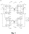
Fig. 1 is a circuit diagram of an embodiment of a dual active bridge (DAB) system in accordance with this disclosure; -
Fig. 2 is a voltage chart of each DAB of the embodiment ofFig. 1 being operated to cancel ripple, wherein the solid line is a first bridge, and the dotted line is a second bridge; and -
Fig. 3 is a current chart of each DAB of the embodiment ofFig. 1 being operated to cancel ripple, wherein the solid line is a first bridge, and the dotted line is a second bridge. - Reference will now be made to the drawings wherein like reference numerals identify similar structural features or aspects of the subject disclosure. For purposes of explanation and illustration, and not limitation, an illustrative view of an embodiment of a system in accordance with the disclosure is shown in
Fig. 1 and is designated generally byreference character 100. Other embodiments and/or aspects of this disclosure are shown inFigs. 2 and 3 . - Referring to
Fig. 1 , a dual active bridge system can include a plurality of dual active bridges (DABs) 101a, 101b. EachDAB 101a, 101b can have afirst side second side DABs 101a, 101b share a commonfirst side capacitor 107 and a commonsecond side capacitor 109. The plurality ofDABs 101a, 101b can be configured to be operated reduce or eliminate ripple current at thefirst side capacitor 107 and/or second side capacitor 109 (e.g., the output capacitor). For example, ripple can be completely cancelled along an entire period length by providing two or more opposing ripples (e.g., two ripples of the same amplitude and line shape but of offset/180 degree phase such that average ripple is zero), or can be reduced by providing two ripples that are not completely opposing (e.g., of differing amplitude and/or shape and/or phase to reduce or cancel total ripple amplitude over at least some period, e.g., a plurality of ripples of a same amplitude/shape but not of fully offset phase which will reduce ripple to a lower amplitude over a portion of the period). - The plurality of
DABs 101a, 101b can include afirst DAB 101a and a second DAB 101b, e.g., as shown. EachDAB 101a, 101b can include first side H-bridge 111a, 111b and a second side H-bridge 113a, 113b. Each H-bridge 111a, 111b can have four switches T1, T2, T3, T4, e.g., disposed in an H configuration as appreciated by those having ordinary skill in the art. Any other suitable number of switches and/or any suitable type of switches (e.g., pulse width modulated transistors) are contemplated herein. Thesystem 100 and/or theDABs 101a, 101b can include any other suitable components (e.g., one or more inductors, a transformer linking eachside - The
system 100 can include acontrol module 115 configured to control the four switches T1, T2, T3, T4 of each H-bridge 111a, b, 113a, b to commutate diagonal switches (e.g., T1 and T4 and T2 and T3) at 50% duty cycle (e.g., such that half of the time T1 and T4 are closed and the other half of the time T2, and T3 are closed). Any other suitable commutation percentage is contemplated herein. However, thecontrol module 115 can be configured to control the four switches T1, T2, T3, T4 on each of the first side H-bridges 111a, 111b and each second side H-bridges 113a, 113b of eachDAB 101a, 101b to cancel ripple. Thecontrol module 115 can include any suitable software module(s) and/or hardware module(s) configured to perform any suitable function(s) and/or method(s) disclosed herein or otherwise. Thecontrol module 115 can be operatively connected to the switches of each H-bridge to control the state of each switch, for example. - The
control module 115 can be configured to control the each H-bridge 111a, 113a of thefirst DAB 101a and each H-bridge 111b, 113b of thesecond DAB 101a, 101b at a common first-side-to-second-side phase shift to control power flow. For example, if the commutation of the first side H-bridge 111a of thefirst DAB 101a is 90 degrees phase shifted relative to the commutation of the second side H-bridge 113a of thefirst DAB 101a, the second DAB 101b can have the same commutation phase shift between thefirst side 103b and thesecond side 105b of the second DAB 101b. - However, for example, the
control module 115 can be configured to control each H-bridge first DAB 101a in an opposite relationship to each corresponding H-bridge 111b, 113b of the second DAB 101b such that duty cycle references between thefirst side 103a of thefirst DAB 101a and thefirst side 103b of the second DAB 101b as well as between thesecond side 105a of thefirst DAB 101a and thesecond side 105b of the second DAB 101b are at or about 180 degrees out of phase to reduce or cancel ripple. For example, in a 180 degree phase, if the switches T1 and T4 of the first side H-bridge 111a of thefirst DAB 101a are closed, then the switches T2, and T3 of the first side H-bridge 111b of the second DAB 101b will be closed (and the remaining switches of each first side H-bridge will be open) such that control on eachfirst side second side - In accordance with at least one aspect of this disclosure, an aircraft electrical system can include a dual active bridge system as disclosed herein, e.g., 100 as described above. Any suitable application (e.g., bidirectional power supply for an electric propulsion system) is contemplated herein.
- In accordance with at least one aspect of this disclosure, a method can include controlling a two or more parallel dual active bridges (DABs) to reduce or cancel output capacitor current ripple. For example, the method can include controlling four switches on each of a first side H-bridge of each DAB and each of a second side H-bridge of each DAB to cancel ripple.
- The method can include controlling each H-bridge of the first DAB and each H-bridge of the second DAB at a common first-side-to-second-side phase shift to control power flow. The method can include controlling each H-bridge of the first DAB in an opposite relationship to each corresponding H-bridge of the second DAB such that duty cycle references between the first side of the first DAB and the first side of the second DAB as well as between the second side of the first DAB and the second side of the second DAB are at or about 180 degrees out of phase to reduce or cancel ripple. Reducing current ripple can include providing a first ripple and a second ripple of differing amplitude and/or shape and/or phase such that a first ripple and a second ripple average to a lower amplitude ripple (if not cancel) over at least a portion (e.g., all or less than all) of a signal period. The method can include any other suitable method(s) and/or portion(s) thereof.
-
Fig. 2 shows voltage across the inductor, showing a voltage plot of the first DAB and the second DAB.Fig. 3 shows current in the inductor showing a current plot of the first DAB and the second DAB.Figs. 2 and 3 show a 180 degree phase relationship between the voltage and current curves between the two DABs. - In certain embodiments, both the input and output bridges of a dual active converter commutate at 50% duty cycle. The phase relationship between input and output bridges determines the flow of power, for example. In embodiments, two smaller (e.g., than traditional) dual active bridge converters can be operated in parallel. They can share a common phase relationship between input and output, in order to share the power as evenly as possible.
- In certain embodiments, the duty cycle references between upper and lower DABs, however, can be 180 degrees out of phase. This can allow the two converters to share the power, but the current ripple will approximately cancel. Specifically, odd current harmonics, including the fundamental, will cancel. This leaves only current sub-fundamentals and even current harmonics to stress the output capacitor, for example.
- Cancellation of all but sub-fundamentals and even harmonics allows the output capacitor to be much smaller and far less constrained. Embodiments of a control module can monitor for a failure in one bridge that could produce ripple in the output capacitor to protect against such failures. Excessive ripple could be sensed by the control module and result in a protective trip to avoid propagation of the failure to the smaller output capacitor.
- While embodiments double the number of bridges, transformers, and inductors each tandem dual active bridge configuration can be smaller than a single large DAB because power is shared. The two bridges can share input and output capacitors, and common control circuitry, for example. Sharing a significantly smaller input and output capacitors can result in a net reduction in size, weight, and/or cost at certain power levels.
- As disclosed above, paralleling two dual active converters with shared input and output capacitors, with same input-to-output phase relationship can allow the two bridges to share power. Furthermore, the two converters can be operated 180 degrees out of phase to provide cancellation of fundamental and odd harmonics. This allows the shared output capacitor to be significantly smaller (and more feasible) than is realizable in a single dual active bridge, for example.
- As will be appreciated by those skilled in the art, aspects of the present disclosure may be embodied as a system, method or computer program product. Accordingly, aspects of this disclosure, e.g., a control module as disclosed above, may take the form of an entirely hardware embodiment, an entirely software embodiment (including firmware, resident software, microcode, etc.), or an embodiment combining software and hardware aspects. For example, a control module as disclosed above can be a single self-contained unit (e.g., of hardware and/or software) or include any suitable number of separate parts or software components. Furthermore, aspects of this dis-closure may take the form of a computer program product embodied in one or more computer readable medium(s) having computer readable program code embodied thereon.
- Any combination of one or more computer readable medium(s) may be utilized. The computer readable medium may be a computer readable signal medium or a computer readable storage medium. A computer readable storage medium may be, for example, but not limited to, an electronic, magnetic, optical, electromagnetic, infrared, or semiconductor system, apparatus, or device, or any suitable combination of the foregoing. More specific examples (a non-exhaustive list) of the computer readable storage medium would include the following: an electrical connection having one or more wires, a portable computer diskette, a hard disk, a random access memory (RAM), a read-only memory (ROM), an erasable programmable read-only memory (EPROM or Flash memory), an optical fiber, a portable compact disc read-only memory (CD-ROM), an optical storage device, a magnetic storage device, or any suitable combination of the foregoing. In the context of this document, a computer readable storage medium may be any tangible medium that can contain, or store a program for use by or in connection with an instruction execution system, apparatus, or device.
- A computer readable signal medium may include a propagated data signal with computer readable program code embodied therein, for example, in baseband or as part of a carrier wave. Such a propagated signal may take any of a variety of forms, including, but not limited to, electromagnetic, optical, or any suitable combination thereof. A computer readable signal medium may be any computer readable medium that is not a computer readable storage medium and that can communicate, propagate, or transport a program for use by or in connection with an instruction execution system, apparatus, or device.
- Program code embodied on a computer readable medium may be transmitted using any appropriate medium, including but not limited to wireless, wireline, optical fiber cable, RF, etc., or any suitable combination of the foregoing.
- Computer program code for carrying out operations for aspects of this disclosure may be written in any combination of one or more programming languages, including an object oriented programming language such as Java, Smalltalk, C++ or the like and conventional procedural programming languages, such as the "C" programming language or similar programming languages. The program code may execute entirely on the user's computer, partly on the user's computer, as a stand-alone software package, partly on the user's computer and partly on a remote computer or entirely on the remote computer or server. In the latter scenario, the remote computer may be connected to the user's computer through any type of network, including a local area network (LAN) or a wide area network (WAN), or the connection may be made to an external computer (for example, through the Internet using an Internet Service Provider).
- Aspects of the this disclosure may be described above with reference to flowchart illustrations and/or block diagrams of methods, apparatus (systems) and computer program products according to embodiments of this disclosure. It will be understood that each block of any flowchart illustrations and/or block diagrams, and combinations of blocks in any flowchart illustrations and/or block diagrams, can be implemented by computer program instructions. These computer program instructions may be provided to a processor of a general purpose computer, special purpose computer, or other programmable data processing apparatus to produce a machine, such that the instructions, which execute via the processor of the computer or other programmable data processing apparatus, create means for implementing the functions/acts specified in any flowchart and/or block diagram block or blocks.
- These computer program instructions may also be stored in a computer readable medium that can direct a computer, other programmable data processing apparatus, or other devices to function in a particular manner, such that the instructions stored in the computer readable medium produce an article of manufacture including instructions which implement the function/act specified in the flowchart and/or block diagram block or blocks.
- The computer program instructions may also be loaded onto a computer, other programmable data processing apparatus, or other devices to cause a series of operational steps to be per-formed on the computer, other programmable apparatus or other devices to produce a computer implemented process such that the instructions which execute on the computer or other programmable apparatus provide processes for implementing the functions/acts specified herein.
- Those having ordinary skill in the art understand that any numerical values disclosed herein can be exact values or can be values within a range. Further, any terms of approximation (e.g., "about", "approximately", "around") used in this disclosure can mean the stated value within a range. For example, in certain embodiments, the range can be within (plus or minus) 20%, or within 10%, or within 5%, or within 2%, or within any other suitable percentage or number as appreciated by those having ordinary skill in the art (e.g., for known tolerance limits or error ranges).
- The articles "a", "an", and "the" as used herein and in the appended claims are used herein to refer to one or to more than one (i.e., to at least one) of the grammatical object of the article unless the context clearly indicates otherwise. By way of example, "an element" means one element or more than one element.
- The phrase "and/or," as used herein in the specification and in the claims, should be understood to mean "either or both" of the elements so conjoined, i.e., elements that are conjunctively present in some cases and disjunctively present in other cases. Multiple elements listed with "and/or" should be construed in the same fashion, i.e., "one or more" of the elements so conjoined. Other elements may optionally be present other than the elements specifically identified by the "and/or" clause, whether related or unrelated to those elements specifically identified. Thus, as a non-limiting example, a reference to "A and/or B", when used in conjunction with open-ended language such as "comprising" can refer, in one embodiment, to A only (optionally including elements other than B); in another embodiment, to B only (optionally including elements other than A); in yet another embodiment, to both A and B (optionally including other elements); etc.
- As used herein in the specification and in the claims, "or" should be understood to have the same meaning as "and/or" as defined above. For example, when separating items in a list, "or" or "and/or" shall be interpreted as being inclusive, i.e., the inclusion of at least one, but also including more than one, of a number or list of elements, and, optionally, additional unlisted items. Only terms clearly indicated to the contrary, such as "only one of' or "exactly one of," or, when used in the claims, "consisting of," will refer to the inclusion of exactly one element of a number or list of elements. In general, the term "or" as used herein shall only be interpreted as indicating exclusive alternatives (i.e., "one or the other but not both") when preceded by terms of exclusivity, such as "either," "one of," "only one of," or "exactly one of."
- Any suitable combination(s) of any disclosed embodiments and/or any suitable portion(s) thereof are contemplated herein as appreciated by those having ordinary skill in the art in view of this disclosure.
- The embodiments of the present disclosure, as described above and shown in the drawings, provide for improvement in the art to which they pertain. While the subject disclosure includes reference to certain embodiments, those skilled in the art will readily appreciate that changes and/or modifications may be made thereto without departing from the spirit and scope of the subject disclosure.
Claims (15)
- A dual active bridge system, comprising:
a plurality of dual active bridges (DABs), each having a first side connected in parallel and a second side connected in parallel such that each of the plurality of DABs share a common first side capacitor (107) and a common second side capacitor (109), the plurality of DABs configured to be operated to reduce or eliminate ripple current at the first side capacitor (107) and/or second side capacitor (109). - The system of claim 1, wherein the plurality of DABs include a first DAB and a second DAB.
- The system of claim 2, wherein each DAB includes a first side H-bridge and a second side H-bridge comprising four switches each.
- The system of claim 3, further comprising a control module (115) configured to control the four switches of each H-bridge to commutate diagonal switches at 50% duty cycle.
- The system of claim 4, wherein the control module is configured to control the four switches on each of the first side and second side H-bridges of each DAB to cancel ripple.
- The system of claim 5, wherein the control module is configured to control the each H-bridge of the first DAB and each H-bridge of the second DAB at a common first-side-to-second-side phase shift to control power flow.
- The system of claim 6, wherein the control module is configured to control each H-bridge of the first DAB in an opposite relationship to each corresponding H-bridge of the second DAB such that duty cycle references between the first side of the first DAB and the first side of the second DAB as well as between the second side of the first DAB and the second side of the second DAB are at or about 180 degrees out of phase to reduce or cancel ripple.
- An aircraft electrical system, comprising: the dual active bridge system of any preceding claim.
- The electrical system of claim 8, wherein the plurality of DABs include a first DAB and a second DAB, and wherein each DAB includes a first side H-bridge and a second side H-bridge comprising four switches each, and further comprising a control module configured to control the four switches of each H-bridge to commutate diagonal switches at 50% duty cycle, and wherein the control module is configured to control the four switches on each of the first side and second side H-bridges of each DAB to cancel ripple, and wherein the control module is configured to control the each H-bridge of the first DAB and each H-bridge of the second DAB at a common first-side-to-second-side phase shift to control power flow, and wherein the control module is configured to control each H-bridge of the first DAB in an opposite relationship to each corresponding H-bridge of the second DAB such that duty cycle references between the first side of the first DAB and the first side of the second DAB as well as between the second side of the first DAB and the second side of the second DAB are at or about 180 degrees out of phase to reduce or cancel ripple.
- The electrical system of claim 9, wherein the control module is configured to sense excessive ripple and to provide a protective trip to avoid propagation of a failure to the smaller output capacitor.
- A method, comprising:
controlling two or more parallel dual active bridges (DABs) to reduce or cancel output capacitor current ripple. - The method of claim 11, wherein controlling includes controlling four switches on each of a first side H-bridge of each DAB and each of a second side H-bridge of each DAB to cancel ripple.
- The method of claim 12, wherein controlling includes controlling each H-bridge of the first DAB and each H-bridge of the second DAB at a common first-side-to-second-side phase shift to control power flow.
- The method of claim 13, wherein controlling includes controlling each H-bridge of the first DAB in an opposite relationship to each corresponding H-bridge of the second DAB such that duty cycle references between the first side of the first DAB and the first side of the second DAB as well as between the second side of the first DAB and the second side of the second DAB are at or about 180 degrees out of phase to reduce or cancel ripple.
- The method of claim any of claims 1 to 14, wherein reducing current ripple includes providing a first ripple and a second ripple of differing amplitude and/or shape and/or phase such that a first ripple and a second ripple average to a lower amplitude ripple over at least a portion of a signal period.
Applications Claiming Priority (1)
| Application Number | Priority Date | Filing Date | Title |
|---|---|---|---|
| US16/671,897 US11165331B2 (en) | 2019-11-01 | 2019-11-01 | Dual active bridge systems for ripple cancelation |
Publications (1)
| Publication Number | Publication Date |
|---|---|
| EP3817207A1 true EP3817207A1 (en) | 2021-05-05 |
Family
ID=73043102
Family Applications (1)
| Application Number | Title | Priority Date | Filing Date |
|---|---|---|---|
| EP20205004.3A Withdrawn EP3817207A1 (en) | 2019-11-01 | 2020-10-30 | Dual active bridge systems for ripple cancelation |
Country Status (2)
| Country | Link |
|---|---|
| US (1) | US11165331B2 (en) |
| EP (1) | EP3817207A1 (en) |
Cited By (3)
| Publication number | Priority date | Publication date | Assignee | Title |
|---|---|---|---|---|
| FR3134932A1 (en) * | 2022-04-26 | 2023-10-27 | Commissariat A L'energie Atomique Et Aux Energies Alternatives | Switching converter |
| WO2024118446A1 (en) * | 2022-11-30 | 2024-06-06 | Deere & Company | Fractional power direct current charging systems and control methods thereof |
| US20240266947A1 (en) * | 2023-02-07 | 2024-08-08 | Murata Manufacturing Co., Ltd. | Two-phase dual-active-bridge dc-dc converter with wide input range |
Families Citing this family (1)
| Publication number | Priority date | Publication date | Assignee | Title |
|---|---|---|---|---|
| DE102018218091A1 (en) * | 2018-10-23 | 2020-04-23 | Audi Ag | DC converter arrangement, fuel cell vehicle and method for operating a DC converter arrangement |
Citations (2)
| Publication number | Priority date | Publication date | Assignee | Title |
|---|---|---|---|---|
| US20130099581A1 (en) * | 2010-06-21 | 2013-04-25 | National University Of Singapore | Energy Storage System |
| US10389166B1 (en) * | 2016-09-23 | 2019-08-20 | Apple Inc. | Method and system for single stage battery charging |
Family Cites Families (10)
| Publication number | Priority date | Publication date | Assignee | Title |
|---|---|---|---|---|
| CA2369060C (en) * | 2001-01-24 | 2005-10-04 | Nissin Electric Co., Ltd. | Dc-dc-converter and bi-directional dc-dc converter and method of controlling the same |
| US7808219B2 (en) * | 2007-11-26 | 2010-10-05 | Honeywell International Inc. | Method and apparatus of capacitor divider based offline AC-DC converter |
| US10063066B2 (en) | 2014-01-07 | 2018-08-28 | Utah State University | Battery control |
| CN105099193A (en) * | 2014-04-16 | 2015-11-25 | 台达电子企业管理(上海)有限公司 | DC/DC power supply device |
| US10277029B2 (en) | 2015-09-30 | 2019-04-30 | Tesla Motors, Inc. | Energy storage system with dual-active-bridge converter |
| WO2017123241A1 (en) * | 2016-01-15 | 2017-07-20 | General Electric Company | System and method for operating a dc to dc power converter |
| WO2018095797A1 (en) | 2016-11-23 | 2018-05-31 | Danmarks Tekniske Universitet | A dual active bridge dc-dc converter comprising current balancing |
| WO2019158567A1 (en) | 2018-02-13 | 2019-08-22 | Danmarks Tekniske Universitet | Dual active bridge dc-dc converter with extended operation range |
| US10224827B1 (en) | 2018-02-15 | 2019-03-05 | Futurewei Technologies, Inc. | Power converter with wide DC voltage range |
| CN109861552A (en) | 2019-03-20 | 2019-06-07 | 中国科学院电工研究所 | Three-phase AC high-efficiency power electronic transformer and its control method |
-
2019
- 2019-11-01 US US16/671,897 patent/US11165331B2/en active Active
-
2020
- 2020-10-30 EP EP20205004.3A patent/EP3817207A1/en not_active Withdrawn
Patent Citations (2)
| Publication number | Priority date | Publication date | Assignee | Title |
|---|---|---|---|---|
| US20130099581A1 (en) * | 2010-06-21 | 2013-04-25 | National University Of Singapore | Energy Storage System |
| US10389166B1 (en) * | 2016-09-23 | 2019-08-20 | Apple Inc. | Method and system for single stage battery charging |
Non-Patent Citations (8)
| Title |
|---|
| CHATTERJEE DHEEMAN ET AL: "HVDC collection system for offshore wind farm", IECON 2016 - 42ND ANNUAL CONFERENCE OF THE IEEE INDUSTRIAL ELECTRONICS SOCIETY, IEEE, 23 October 2016 (2016-10-23), pages 4145 - 4150, XP033034309, DOI: 10.1109/IECON.2016.7794107 * |
| GRZEJSZCZAK PIOTR ET AL: "Bidirectional modular DC/DC converter for directcurrent microgrids", 2017 PROGRESS IN APPLIED ELECTRICAL ENGINEERING (PAEE), IEEE, 25 June 2017 (2017-06-25), pages 1 - 7, XP033141831, DOI: 10.1109/PAEE.2017.8008985 * |
| SHA DESHANG ET AL: "Dynamic Response Improvements of Parallel-Connected Bidirectional DC-DC Converters for Electrical Drive Powered by Low-Voltage Battery Employing Optimized Feedforward Control", IEEE TRANSACTIONS ON POWER ELECTRONICS, INSTITUTE OF ELECTRICAL AND ELECTRONICS ENGINEERS, USA, vol. 32, no. 10, 1 October 2017 (2017-10-01), pages 7783 - 7794, XP011649015, ISSN: 0885-8993, [retrieved on 20170510], DOI: 10.1109/TPEL.2016.2637370 * |
| SHA DESHANG ET AL: "Parallel-connected bidirectional current-fed dual active bridge DC-DC converters with decentralized control", 2016 IEEE ENERGY CONVERSION CONGRESS AND EXPOSITION (ECCE), 18 September 2016 (2016-09-18), pages 1 - 7, XP055783202, ISBN: 978-1-5090-0737-0, DOI: 10.1109/ECCE.2016.7855329 * |
| SHIVA S M ET AL: "A new phase shedding and phase adding control scheme for interleaved DAB converter operating in IPOP configuration", 2015 IEEE INTERNATIONAL TELECOMMUNICATIONS ENERGY CONFERENCE (INTELEC), IEEE, 18 October 2015 (2015-10-18), pages 1 - 6, XP032968696, DOI: 10.1109/INTLEC.2015.7572420 * |
| SUCAMELI MATTEO: "Design and performance evaluation of a digitally controlled 1 kW three-phase interleaved ZVS converter for plug-in EV and HEV battery charger", 2015 IEEE APPLIED POWER ELECTRONICS CONFERENCE AND EXPOSITION (APEC), IEEE, 15 March 2015 (2015-03-15), pages 3101 - 3108, XP032775357, DOI: 10.1109/APEC.2015.7104794 * |
| TARISCIOTTI LUCA ET AL: "Evaluation of isolated DC/DC converter topologies for future HVDC aerospace microgrids", 2017 IEEE ENERGY CONVERSION CONGRESS AND EXPOSITION (ECCE), IEEE, 1 October 2017 (2017-10-01), pages 2238 - 2245, XP033247088, DOI: 10.1109/ECCE.2017.8096437 * |
| WANG YUBIN ET AL: "Sensorless parameter estimation and current-sharing strategy in two-phase and multiphase IPOP DAB DC-DC converters", IET POWER ELECTRONICS, IET, UK, vol. 11, no. 6, 29 May 2018 (2018-05-29), pages 1135 - 1142, XP006067354, ISSN: 1755-4535, DOI: 10.1049/IET-PEL.2017.0860 * |
Cited By (4)
| Publication number | Priority date | Publication date | Assignee | Title |
|---|---|---|---|---|
| FR3134932A1 (en) * | 2022-04-26 | 2023-10-27 | Commissariat A L'energie Atomique Et Aux Energies Alternatives | Switching converter |
| WO2023208873A1 (en) | 2022-04-26 | 2023-11-02 | Commissariat A L'energie Atomique Et Aux Energies Alternatives | Switched-mode converter |
| WO2024118446A1 (en) * | 2022-11-30 | 2024-06-06 | Deere & Company | Fractional power direct current charging systems and control methods thereof |
| US20240266947A1 (en) * | 2023-02-07 | 2024-08-08 | Murata Manufacturing Co., Ltd. | Two-phase dual-active-bridge dc-dc converter with wide input range |
Also Published As
| Publication number | Publication date |
|---|---|
| US11165331B2 (en) | 2021-11-02 |
| US20210135561A1 (en) | 2021-05-06 |
Similar Documents
| Publication | Publication Date | Title |
|---|---|---|
| US11165331B2 (en) | Dual active bridge systems for ripple cancelation | |
| Liserre* et al. | Step-by-step design procedure for a grid-connected three-phase PWM voltage source converter | |
| CN102971949B (en) | Harmonics elimination interphase magnetic device | |
| Ghoshal et al. | Active damping of LCL filter at low switching to resonance frequency ratio | |
| Rivera et al. | Review of predictive control methods to improve the input current of an indirect matrix converter | |
| US7219673B2 (en) | Transformerless multi-level power converter | |
| JPS62501814A (en) | Multiphase DC-DC series resonant converter | |
| JP5217397B2 (en) | Parallel operation control system for power converter | |
| US8760896B2 (en) | Multilevel regeneration drive system | |
| Zhou et al. | Transformer‐less dynamic voltage restorer based on a three‐leg ac/ac converter | |
| WO2023058367A1 (en) | Voltage regulator and power conversion device | |
| WO2017086863A1 (en) | Combined common mode inductor and differential signal transformer | |
| Ku et al. | Fault-tolerant control strategy for open-circuit fault of two-parallel-connected three-phase AC–DC two-level PWM converter: H.-K. Ku et al. | |
| US9979205B2 (en) | Methods and circuits configured to provide for multi-phase wireless power transfer | |
| US20220393602A1 (en) | Feedforward compensation for llc resonant converters | |
| US11973483B2 (en) | Coupled filter inductor for interleaved power converter | |
| EP3499701B1 (en) | Bi-directional dc to dc signal conversion using observer based estimated current sensor | |
| KR20170027178A (en) | Power conversion system having filters utilizing the phase of voltage harmonics | |
| Jeelani et al. | Analysis of various modulation techniques for high-frequency isolated single-phase modified quasi-Z-source AC–AC converter-based solid-state transformer | |
| EP2752979A1 (en) | Power supply device | |
| EP3566290B1 (en) | Power supply and power supply method with circulation current compensation | |
| Torrico‐Bascopé et al. | Three‐state switching cell (3SSC)‐based non‐isolated dc–dc boost‐type converter with balanced output voltage and wide voltage conversion range | |
| EP4270759A1 (en) | Universal buck-boost topology with an active positive holdup voltage | |
| Saha | Power balance control scheme for a cascaded matrix-based dual-active-bridge (CMB-DAB) converter | |
| JP5407329B2 (en) | DC power supply device and reactor device |
Legal Events
| Date | Code | Title | Description |
|---|---|---|---|
| PUAI | Public reference made under article 153(3) epc to a published international application that has entered the european phase |
Free format text: ORIGINAL CODE: 0009012 |
|
| STAA | Information on the status of an ep patent application or granted ep patent |
Free format text: STATUS: THE APPLICATION HAS BEEN PUBLISHED |
|
| AK | Designated contracting states |
Kind code of ref document: A1 Designated state(s): AL AT BE BG CH CY CZ DE DK EE ES FI FR GB GR HR HU IE IS IT LI LT LU LV MC MK MT NL NO PL PT RO RS SE SI SK SM TR |
|
| STAA | Information on the status of an ep patent application or granted ep patent |
Free format text: STATUS: REQUEST FOR EXAMINATION WAS MADE |
|
| 17P | Request for examination filed |
Effective date: 20211105 |
|
| RBV | Designated contracting states (corrected) |
Designated state(s): AL AT BE BG CH CY CZ DE DK EE ES FI FR GB GR HR HU IE IS IT LI LT LU LV MC MK MT NL NO PL PT RO RS SE SI SK SM TR |
|
| STAA | Information on the status of an ep patent application or granted ep patent |
Free format text: STATUS: EXAMINATION IS IN PROGRESS |
|
| 17Q | First examination report despatched |
Effective date: 20220915 |
|
| STAA | Information on the status of an ep patent application or granted ep patent |
Free format text: STATUS: THE APPLICATION HAS BEEN WITHDRAWN |
|
| 18W | Application withdrawn |
Effective date: 20241014 |