EP3817188A1 - Method and device for wireless charging, wireless charging transmitter and storage medium - Google Patents
Method and device for wireless charging, wireless charging transmitter and storage medium Download PDFInfo
- Publication number
- EP3817188A1 EP3817188A1 EP20169155.7A EP20169155A EP3817188A1 EP 3817188 A1 EP3817188 A1 EP 3817188A1 EP 20169155 A EP20169155 A EP 20169155A EP 3817188 A1 EP3817188 A1 EP 3817188A1
- Authority
- EP
- European Patent Office
- Prior art keywords
- terminal
- charging
- information
- efficiency
- orientation
- Prior art date
- Legal status (The legal status is an assumption and is not a legal conclusion. Google has not performed a legal analysis and makes no representation as to the accuracy of the status listed.)
- Pending
Links
Images


Classifications
-
- H—ELECTRICITY
- H02—GENERATION; CONVERSION OR DISTRIBUTION OF ELECTRIC POWER
- H02J—ELECTRIC POWER NETWORKS; CIRCUIT ARRANGEMENTS OR SYSTEMS FOR SUPPLYING OR DISTRIBUTING ELECTRIC POWER; SYSTEMS FOR STORING ELECTRIC ENERGY
- H02J50/00—Circuit arrangements or systems for wireless supply or distribution of electric power
- H02J50/90—Circuit arrangements or systems for wireless supply or distribution of electric power involving detection or optimisation of position, e.g. alignment
-
- H—ELECTRICITY
- H02—GENERATION; CONVERSION OR DISTRIBUTION OF ELECTRIC POWER
- H02J—ELECTRIC POWER NETWORKS; CIRCUIT ARRANGEMENTS OR SYSTEMS FOR SUPPLYING OR DISTRIBUTING ELECTRIC POWER; SYSTEMS FOR STORING ELECTRIC ENERGY
- H02J50/00—Circuit arrangements or systems for wireless supply or distribution of electric power
- H02J50/10—Circuit arrangements or systems for wireless supply or distribution of electric power using inductive coupling
- H02J50/12—Circuit arrangements or systems for wireless supply or distribution of electric power using inductive coupling of the resonant type
-
- H—ELECTRICITY
- H02—GENERATION; CONVERSION OR DISTRIBUTION OF ELECTRIC POWER
- H02J—ELECTRIC POWER NETWORKS; CIRCUIT ARRANGEMENTS OR SYSTEMS FOR SUPPLYING OR DISTRIBUTING ELECTRIC POWER; SYSTEMS FOR STORING ELECTRIC ENERGY
- H02J50/00—Circuit arrangements or systems for wireless supply or distribution of electric power
- H02J50/20—Circuit arrangements or systems for wireless supply or distribution of electric power using microwaves or radio frequency waves
-
- H—ELECTRICITY
- H02—GENERATION; CONVERSION OR DISTRIBUTION OF ELECTRIC POWER
- H02J—ELECTRIC POWER NETWORKS; CIRCUIT ARRANGEMENTS OR SYSTEMS FOR SUPPLYING OR DISTRIBUTING ELECTRIC POWER; SYSTEMS FOR STORING ELECTRIC ENERGY
- H02J50/00—Circuit arrangements or systems for wireless supply or distribution of electric power
- H02J50/80—Circuit arrangements or systems for wireless supply or distribution of electric power involving the exchange of data, concerning supply or distribution of electric power, between transmitting devices and receiving devices
-
- H—ELECTRICITY
- H02—GENERATION; CONVERSION OR DISTRIBUTION OF ELECTRIC POWER
- H02J—ELECTRIC POWER NETWORKS; CIRCUIT ARRANGEMENTS OR SYSTEMS FOR SUPPLYING OR DISTRIBUTING ELECTRIC POWER; SYSTEMS FOR STORING ELECTRIC ENERGY
- H02J7/00—Circuit arrangements for charging or discharging batteries or for supplying loads from batteries
- H02J7/40—Circuit arrangements for charging or discharging batteries or for supplying loads from batteries characterised by the exchange of charge or discharge related data
- H02J7/42—Circuit arrangements for charging or discharging batteries or for supplying loads from batteries characterised by the exchange of charge or discharge related data with electronic devices having internal batteries, e.g. mobile phones
-
- H—ELECTRICITY
- H02—GENERATION; CONVERSION OR DISTRIBUTION OF ELECTRIC POWER
- H02J—ELECTRIC POWER NETWORKS; CIRCUIT ARRANGEMENTS OR SYSTEMS FOR SUPPLYING OR DISTRIBUTING ELECTRIC POWER; SYSTEMS FOR STORING ELECTRIC ENERGY
- H02J7/00—Circuit arrangements for charging or discharging batteries or for supplying loads from batteries
- H02J7/50—Circuit arrangements for charging or discharging batteries or for supplying loads from batteries acting upon multiple batteries simultaneously or sequentially
Definitions
- the present disclosure generally relates to the technical field of wireless charging, and more specifically, to a method and a device for wireless charging, a wireless charging transmitter and a storage medium.
- an electromagnetic-induction-based Wireless Power Consortium (SPC) standard and a magnetic resonance technology-based AirFuel Alliance (AFA) standard are adopted for mainstream wireless charging solutions.
- the AFA standard is a standard established by the AFA. Since a technology maturity of the AFA standard is too low to meet a commercial requirement, the WPC standard is adopted for all wireless charging solutions on the present market.
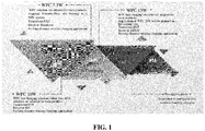
- FIG. 1 illustrates wireless charging solutions for products of mainstream mobile phone manufacturers (a company A, a company B, a company C and a company D). It can be seen that present wireless charging solutions of the mainstream mobile phone manufacturers are all WPC solutions and applied to short-distance wireless charging within 5mm between a transmitting device and a receiving device. With increasing extension of Internet of everything scenarios, long-distance wireless charging solutions have become more and more important. However, with remarkable improvement of the degree of freedom of long-distance wireless charging, charging efficiency is difficult to reach ideal charging efficiency that is required.
- the present disclosure provides a method and a device for wireless charging, a wireless charging transmitter and a storage medium.
- a method for wireless charging which may be applied to a wireless charging transmitter and include that:
- first prompting information is output, herein the first prompting information is used to prompt an adjustment of the position-orientation information of the terminal.
- the position-orientation information of the terminal for wireless charging based on the radio frequency signal transmitted by the wireless charging transmitter is acquired; whether the terminal is in the target charging state is determined based on the position-orientation information; and responsive to that it is determined that the terminal is not in the target charging state, prompting information for adjusting the position-orientation information of the terminal may be output to prompt a user to adjust the position-orientation of the terminal, so that subsequent adjustment of the terminal to a proper position-orientation for meeting a requirement that the terminal is in the target charging state and improving charging efficiency of the terminal is facilitated.
- Whether the terminal is in the target charging state is determined through the position-orientation information, and when the terminal is not in the target charging state, the position-orientation of the terminal is changed to improve the charging efficiency.
- Such a manner is easy to operate and implement, and a user experience is also greatly improved.
- the operation that whether the terminal is in the target charging state is determined based on the position-orientation information may include that:
- charging efficiency corresponding to the position-orientation information is determined based on a predetermined correspondences between position-orientations of the terminal and charging efficiency;
- the operation that responsive to that the charging efficiency is within the preset charging efficiency range, it is determined that the terminal is in the target charging state may include that:
- the method may further include that:
- second prompting information is output based on the position-orientation information and a position-orientation of the terminal corresponding to charging efficiency within the preset charging efficiency range
- the second prompting information is used to prompt a parameter for adjusting the position-orientation of the terminal
- the adjustment parameter includes at least one parameter of: a direction in which a position of the terminal is adjusted, a distance by which the position of the terminal is adjusted or an orientation of the terminal.
- the method may further include that:
- third prompting information is output, herein the third prompting information is used to prompt that the terminal is in the target charging state.
- the method may further include that:
- first receiving power returned by the terminal based on first transmitting power is received, herein the first transmitting power is power at which the radio frequency signal is transmitted by the wireless charging transmitter;
- first transmission efficiency is determined based on the first transmitting power and the first receiving power
- the position-orientation information includes at least one of position information or orientation information, herein the position information represents a distance between the terminal and the wireless charging transmitter, or a space distribution of the terminal; and the orientation information represents that the terminal is lying flat, vertical or at an angle with respect to the horizontal plane, or is orientation information or direction information of the terminal.
- a device for wireless charging which may include:
- an acquisition module configured to acquire position-orientation information of a terminal for wireless charging based on a radio frequency signal transmitted by a wireless charging transmitter
- a determination module configured to determine, based on the position-orientation information, whether the terminal is in a target charging state
- a processing module configured to, responsive to that it is determined that the terminal is not in the target charging state, output first prompting information, herein the first prompting information is used to prompt an adjustment of the position-orientation information of the terminal.
- the determination module may include:
- a first determination unit configured to determine, based on a predetermined correspondences between position-orientations of the terminal and charging efficiency, charging efficiency corresponding to the position-orientation information
- a second determination unit configured to, responsive to that the charging efficiency is within a preset charging efficiency range, determine that the terminal is in the target charging state and, responsive to that the charging efficiency is outside of the preset charging efficiency range, determine that the terminal is not in the target charging state.
- the second determination unit may be configured to, responsive to that the charging efficiency is maximum charging efficiency in the correspondences, determine that the terminal is in the target charging state.
- the processing module may further be configured to, responsive to that the terminal is not in the target charging state, output second prompting information based on the position-orientation information and a position-orientation of the terminal corresponding to charging efficiency within the preset charging efficiency range,
- the second prompting information is used to prompt an adjustment parameter for adjusting the position-orientation of the terminal, and the adjustment parameter includes at least one parameter of a direction in which a position of the terminal is adjusted, a distance by which the position of the terminal is adjusted or an orientation of the terminal.
- the processing module may be configured to, responsive to that it is determined that the terminal is in the target charging state, output third prompting information, herein the third prompting information is used to prompt that the terminal is in the target charging state.
- the acquisition module may be configured to receive first receiving power returned by the terminal based on first transmitting power, herein the first transmitting power is power at which the radio frequency signal is transmitted by the wireless charging transmitter; and
- the determination module may further include:
- a third determination unit configured to determine first transmission efficiency based on the first transmitting power and the first receiving power
- the second determination unit responsive to that it is determined that a difference between the first transmission efficiency and the maximum charging efficiency is less than a first threshold value, determine that the terminal is in the target charging state.
- another wireless charging transmitter which may include:
- processor may be configured to run computer service to implement the method for wireless charging of any embodiment of the present disclosure.
- a non-transitory computer-readable storage medium having stored therein executable program that when being executed by a processor, implement the method for wireless charging of any embodiment of the present disclosure.
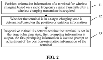
- FIG. 2 is a flow chart showing a method for wireless charging, according to an exemplary embodiment. As shown in FIG. 2 , the method for wireless charging is applied to a wireless charging transmitter and includes the following steps.
- position-orientation information of a terminal for wireless charging based on a radio frequency signal transmitted by the wireless charging transmitter is acquired.
- first prompting information is output, and the first prompting information is used to prompt an adjustment of the position-orientation information of the terminal.
- the wireless charging transmitter may be any electronic device capable of transmitting a radio frequency signal.
- the terminal may be any electronic device capable of receiving a radio frequency signal.
- the terminal may be a mobile communication device, a Bluetooth earphone, a smart watch or band, or a notebook computer, etc.
- the position-orientation information includes position information and/or orientation information.
- the position information may be a distance between the terminal and the wireless charging transmitter, or the position information may also be a space distribution of the terminal.
- a terminal is 5m away from a door and 3m away from a window.
- the orientation information may be that the terminal is lying flat, vertical or at a certain angle with respect to the horizontal plane, or the orientation information may also be orientation information or direction information of the terminal.
- the terminal faces 45° southwest.
- the terminal faces a direction opposite to a direction in which the wireless charging transmitter transmits the radio frequency signal.
- an angle between the terminal and a transmitting direction of the radio frequency signal may be determined based on the position-orientation information.
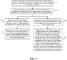
- S12 includes the following steps.
- charging efficiency corresponding to the position-orientation information is determined based on predetermined correspondences between position-orientations of the terminal and charging efficiencies.
- the correspondences between the position-orientations of the terminal and the charging efficiencies may be in form of a table or a list, or may be in form of an array, etc.
- the position-orientation information includes a distance and an angle.
- specific implementation of the correspondences is only required to meet such a form that ⁇ distance, angle ⁇ corresponds to charging efficiency one to one, and there are no limits made herein.
- Table 1 provides the correspondences between the position-orientations of the terminal and charging efficiencies.
- the correspondences are in the table form.
- Distances in each position-orientation information of the terminal include D 1 , D 2 , D 3 , ..., D n
- angles in each position-orientation information of the terminal include ⁇ 1 , ⁇ 2 , ⁇ 3 , ..., ⁇ n .
- the position-orientation information (D 1 , ⁇ 1 ), (D 1 , ⁇ 2 ), ..., (D 1 , ⁇ n ), (D 2 , ⁇ 1 ), (D 2 , ⁇ 2 ), ..., (D 2 , ⁇ n ), (D 3 , ⁇ 1 ), ..., (D n , ⁇ n ) of the terminal correspond to charging efficiency P 11 , P 12 , ..., P 1n , P 21 , P 22 , ..., P 2n , P 31 , ..., P nn respectively, specifically as shown in Table 1.
- preset charging efficiency may be charging efficiency greater than or equal to a second threshold value.
- the preset charging efficiency is a value greater than or equal to 30%.
- the preset charging efficiency may be charging efficiency at a relatively high charging efficiency rank.
- the preset charging efficiency may be 55% to 60%.
- the correspondences between the position-orientations of the terminal and charging efficiencies may be established in advance; the present charging efficiency corresponding to the position-orientation information is determined based on the acquired position-orientation information of the terminal and the correspondences; whether the present charging efficiency is charging efficiency corresponding to the target charging state is determined, if the present charging efficiency is charging efficiency corresponding to the target charging state, it is determined that the terminal is in the target charging state, and if the present charging efficiency is not charging efficiency corresponding to the target charging state, it is determined that the terminal is not in the target charging state. Therefore, whether the terminal is in the relatively ideal target charging state may be accurately determined based on the correspondences. Moreover, such a manner is simple and easy to implement.
- S 122b includes that:
- the maximum charging efficiency is 60%.
- each charging efficiency in the correspondences may be compared to determine the maximum charging efficiency. Then, the present charging efficiency corresponding to the position-orientation information of the terminal is queried based on the correspondences. If it is determined that the charging efficiency is the maximum charging efficiency, it is determined that the terminal is in the target charging state, and if NO, it is determined that the terminal is not in the target charging state. Therefore, in the embodiment, the more ideal target charging state of the terminal is further determined to further improve charging efficiency of the terminal when the position-orientation of the terminal is subsequently adjusted based on position-orientation information corresponding to the maximum charging efficiency.
- the first prompting information is displayed on a display screen of the wireless charging transmitter.
- prompting information such as "the terminal is not in the target charging state, please timely adjust the position-orientation information of the terminal" is displayed on the display screen of the wireless charging transmitter.
- a first prompting voice is produced.
- the first prompting information includes the first prompting voice.
- a first voice module may be arranged in the wireless charging transmitter, and a prompting voice that "the terminal is not in the target charging state, please adjust the position-orientation information of the terminal" is produced based on the voice module.
- the method further includes that: the first prompting information is sent to the terminal, the first prompting information is used to be displayed by the terminal based on a display screen of the terminal.
- the first prompting information is sent to the terminal, the first prompting information is used to be displayed by the terminal based on a display screen of the terminal.
- the position-orientation information of the terminal may be acquired; whether the terminal is in the target charging state is determined based on the position-orientation information; and if the terminal is not in the target charging state, prompting information for adjusting the position-orientation information of the terminal is output to prompt the user to adjust the position-orientation of the terminal, so that subsequent adjustment of the terminal to a proper position-orientation for meeting a requirement that the terminal is in the target charging state and improving charging efficiency of the terminal is facilitated.
- the charging efficiency corresponding to the position-orientation is determined via the predetermined correspondences between the position-orientations of the terminal and the charging efficiencies, and whether the terminal is in the target charging state is determined based on whether the charging efficiency is within the preset charging efficiency range, so that the ideal target charging state of the terminal may be accurately determined.
- whether the charging efficiency is the maximum charging efficiency in the correspondences is determined to determine whether the terminal with the position-orientation information is in the target charging state, so that the more ideal charging state may further be determined to further improve the charging efficiency of the terminal when the position-orientation of the terminal is subsequently adjusted based on the position-orientation information corresponding to the maximum charging efficiency.
- Whether the terminal is in the target charging state is determined via the position-orientation information, and if the terminal is not in the target charging state, the position-orientation of the terminal is changed to improve the charging efficiency.
- Such a manner is easy to operate and implement, and a user experience is also greatly improved.
- the method further includes the following step.
- second prompting information is output based on the position-orientation information and a position-orientation of the terminal corresponding to charging efficiency within the preset charging efficiency range
- the second prompting information is used to prompt an adjustment parameter for adjusting the position-orientation of the terminal
- the adjustment parameter includes at least one parameter of: a direction in which a position of the terminal is adjusted, a distance by which the position of the terminal is adjusted or an orientation of the terminal.
- charging efficiency corresponding to the target charging state may be the preset charging efficiency; or, the charging efficiency corresponding to the target charging state may also be the maximum charging efficiency in the correspondences.
- a distance by which the position of the terminal is adjusted may be a distance corresponding to the preset charging efficiency.
- a present position of the terminal is 7m far away from the wireless charging transmitter, and the distance corresponding to the preset charging efficiency is 5m to 6m far away from the wireless charging transmitter.
- a distance by which the position of the terminal is adjusted may be 1m to 2m.
- a distance by which the position of the terminal is adjusted may be a distance corresponding to the maximum charging efficiency.
- the present position of the terminal is 7m far away from the wireless charging transmitter, and the distance corresponding to the maximum charging efficiency is 5.5m far away from the wireless charging transmitter.
- the direction in which a position of the terminal is adjusted or the orientation of the position of the terminal may be considered as adjusting the angle of the terminal in a practical application. Orientation in which a position of the terminal is adjusted is adjusted based on a first angle, and a direction in which a position of the terminal is adjusted is adjusted based on a second angle, and the first angle is greater than the second angle.
- an angle by which the terminal is adjusted may be the distance corresponding to the preset charging efficiency.
- a present angle between the terminal and the radio frequency signal transmitted by the wireless charging transmitter is 10°
- an angle, corresponding to the preset charging efficiency, with the radio frequency signal transmitted by the wireless charging transmitter is 15° to 20°.
- an angle by which the terminal is adjusted is 5° to 10°.
- the angle by which the terminal is adjusted may be the distance corresponding to the maximum charging efficiency.
- the present angle between the terminal and the radio frequency signal transmitted by the wireless charging transmitter is 10°
- an angle, corresponding to the maximum charging efficiency, with transmission of the radio frequency signal by the wireless charging transmitter is 18°.
- an angle by which the terminal is adjusted is 8°.
- the second prompting information is displayed by use of the display screen of the wireless charging transmitter.
- prompting information such as "the terminal is not in the target charging state, please adjust the terminal to be 1m far away from the wireless charging transmitter” or "please adjust the terminal to be deflected 5° southwestwards" is displayed on the display screen.
- a second prompting voice is produced.
- a prompting voice such as "the terminal is not in the target charging state, please adjust the terminal to be 1m far away from the wireless charging transmitter” or "please adjust the terminal to be deflected 5° southwestwards" is produced by use of the voice module of the wireless charging transmitter.
- the method further includes that: the second prompting information is sent to the terminal.
- the second prompting information is displayed by the terminal based on the display screen of the terminal. Therefore, the user may conveniently see the adjustment parameter which is suggested to adjust position information of the terminal on the terminal, and great convenience is brought to operations of the user.
- the difference between the position-orientation of the terminal corresponding to the charging efficiency within the preset charging efficiency range and the position-orientation information may be determined, and a prompt about adjustment of parameter information is made based on the difference, so that the user may favorably adjust the position-orientation of the terminal based on the prompting information.
- the distance between the terminal and the wireless charging transmitter is adjusted, and/or the angle between the terminal and the radio frequency signal is adjusted, so that the position-orientation of the terminal may be adjusted from many aspects, and adjustment of the position-orientation of the terminal for meeting the requirement that the terminal is in the target charging state and improving the charging efficiency of the terminal is facilitated.
- the method further includes the following step.
- third prompting information is output, and the third prompting information is used to prompt that the terminal is in the target charging state.
- the operation that the third prompting information is output may also include at least one of the following operations: the third prompting information is displayed by use of the display screen of the wireless charging transmitter; and a third prompting voice is produced by use of the voice module of the wireless charging transmitter.
- prompting information such as "the terminal is in the target charging state" is displayed on the display screen of the wireless charging transmitter.
- the method further includes that: the third prompting information is sent to the terminal, and the third prompting information is displayed by the terminal based on the display screen of the terminal. Therefore, the user may conveniently see the prompting information on the terminal.
- the third prompting information may be output to prompt the user that the terminal is charged at a relatively ideal position-orientation and the position-orientation of the terminal is not required to be adjusted.
- the method further includes that:
- first receiving power returned by the terminal based on first transmitting power is received, and the first transmitting power is power at which the radio frequency signal is transmitted by the wireless charging transmitter;
- first transmission efficiency is determined based on the first transmitting power and the first receiving power
- the operation that: responsive to that it is determined that the difference between the first transmission efficiency and the maximum charging efficiency is less than the first threshold value, it is determined that the terminal is in the target charging state may be implemented as follows: responsive to that it is determined that the first transmission efficiency is within the preset charging efficiency range, it is determined that the terminal is in the target charging state.
- the method further includes that:
- charging efficiency calculated based on the position-orientation information in the abovementioned embodiments is the first transmission efficiency in the embodiments.
- the first transmission efficiency may directly be compared with the preset charging efficiency to determine whether the terminal is in the target charging state. Another manner for determining the target charging state is provided, and the manner is simple and easy to implement.
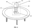
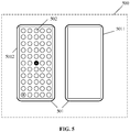
- the wireless charging transmitter 400 includes: a supporting body 401, a display screen 404 and at least one first radio frequency antenna 405 which are placed on an outer surface of the supporting body;
- the wireless charging transmitter may be designed into a state like a desk lamp, and then the wireless charging transmitter may be placed on a desk or an office table, etc. Therefore, a user may conveniently view data displayed on the display screen, and convenience is brought to the user.
- a light-emitting component may further be arranged in the wireless charging transmitter, thereby endowing the wireless charging transmitter with a basic function of a desk lamp.
- the wireless charging transmitter may be placed at any other position, for example, placed on a ceiling of an office or suspended on a door.
- the terminal 500 includes:
- the at least one second radio frequency antenna 502 may be arranged on the rear housing 5012 of the mobile phone and may specifically be arranged on the outer surface of the rear housing 5012.
- the at least one second radio frequency antenna 502 may be arranged in form of an antenna array. Therefore, a size and a direction of a radiation field are changed in form of the antenna array to maximally receive a radio frequency signal.
- the at least one second radio frequency antenna 502 is arranged on the outer surface of the rear housing 5012, so that the influence on the screen-to-body ratio of the screen of the terminal may be avoided; and moreover, the at least one second radio frequency antenna 502 is arranged on the outer surface of the rear housing 5012, so that influence on reception of the radio frequency signal may be avoided no matter which material the housing of the terminal is made of.
- a charging efficiency calculation method for a wireless charging system is also provided below.
- the overall charging efficiency is determined based on first transmission efficiency of a transceiver antenna, second transmission efficiency of the wireless charging transmitter and third transmission efficiency of the terminal.
- the calculation method for the overall charging efficiency includes the following steps.
- the first transmission efficiency of the transceiver antenna is calculated.
- the first transmission efficiency is transmission efficiency between the wireless charging transmitter and the terminal.
- wireless charging is implemented in a near field region.
- G t and G r are 26.4dBi and 20.65dBi
- ⁇ is 0.03125m
- L t is 0.3dB
- the loss G r ( ⁇ r ⁇ r ) produced by the alignment error of the receiving node is 0.2
- ⁇ T - R 55.9% is calculated.
- the second transmission efficiency is overall efficiency of a transmitting channel of the wireless charging transmitter.
- P DIS is calculated as follows.
- P T is calculated as follows.
- Output of a single-channel power amplifier is 28.7dBm, and considering power reduction caused by joint loss, other loss and temperature rises, the output at a normal temperature is 28dBm (0.63W).
- the third transmission efficiency is conversion efficiency of a rectified current of the terminal.
- the first transmission efficiency is practically determined based on position-orientation information (including a distance with the wireless charging transmitter and an angle of the terminal) of the terminal, and is the charging efficiency in the abovementioned embodiment.
- the second transmission efficiency and/or the third transmission efficiency may also be changed. For example, at least one of the total output power of the phased array transmitting channel and the output power of the rectifier circuit may be improved. There are no limits made herein.
- FIG. 6 is a flow chart showing a method for wireless charging, according to an exemplary embodiment. As shown in FIG. 6 , the method for wireless charging is applied to a wireless charging system, the wireless charging system including a wireless charging transmitter and a mobile phone. The method includes the following steps.
- a charging efficiency truth table is established, and a first distance and first orientation information corresponding to maximum charging efficiency are determined.
- the wireless charging transmitter establishes the charging efficiency truth table based on each position-orientation of the terminal and corresponding charging efficiency, and determines the first distance and first orientation information corresponding to the maximum charging efficiency based on the charging efficiency truth table.
- the mobile phone starts to be charged.
- a second distance and second orientation information of the mobile phone are detected.
- the wireless charging transmitter detects the second distance and second orientation information of the mobile phone.
- the second distance and the second orientation information may be determined based on position information, received by the wireless charging transmitter, of the terminal.
- the wireless charging transmitter compares the first distance and the second distance to determine whether the second distance is the same as the first distance, and compares the first orientation information and the second orientation information to determine whether the second orientation information is the same as the first orientation information.
- a distance parameter for adjusting is determined based on the first distance and the second distance; and/or, if the first orientation information is different from the second orientation information, an angle parameter for adjusting is determined based on the first orientation information and the second orientation information.
- first prompting information is displayed via a display screen, the first prompting information is used to prompt that the mobile phone is not in a target charging state and prompt to adjust the distance of the mobile phone as a third distance and/or a orientation of the mobile phone as a third angle.
- the wireless charging transmitter displays the first prompting information via the display screen, the first prompting information is used to prompt that the mobile phone is not in the target charging state and suggest to adjust the distance of the mobile phone as the third distance and/or the orientation of the mobile phone as the third angle.
- the first prompting information is received, and the first prompting information is displayed on a display screen of the mobile phone.
- the mobile phone receives the first prompting information and displays the first prompting information on the display screen of the mobile phone.
- prompting information that "the mobile phone is not in the target charging state, and it is suggested to adjust the distance of the mobile phone as the third distance and/or the orientation of the mobile phone as the third angle" is displayed.
- the first distance and first position-orientation information of the mobile phone are adjusted based on the first prompting information.
- a user may adjust the first distance and first orientation information of the mobile phone based on the first prompting information in block 207. Specifically, the distance of the mobile phone is adjusted by the third distance to reach the first distance, and orientation information of the mobile phone is adjusted by the third angle to achieve an orientation corresponding to the first orientation information.
- third prompting information is displayed via the display screen, the third prompting information is prompting information used to prompt that the mobile phone is in the target charging state.
- the wireless charging transmitter displays the third prompting information that the mobile phone is in the target charging state via the display screen of the wireless charging transmitter.
- the charging efficiency truth table is established, the distance and orientation corresponding to the maximum charging efficiency are determined, whether the mobile phone is in the target charging state is determined based on whether a present distance and orientation for charging of the mobile phone are the distance and orientation corresponding to the maximum charging efficiency, and if NO, the distance and orientation of the mobile phone are adjusted to the distance and orientation corresponding to the maximum charging efficiency, so that charging efficiency of the mobile phone is improved.
- the distance and orientation of the terminal are changed to improve the charging efficiency. Such a manner is easy to operate and implement, and a user experience is also greatly improved.
- FIG. 7 is a block diagram of a device for wireless charging, according to an example.
- the device includes:
- the determination module 72 includes:
- the second determination unit 722 is configured to, responsive to that the charging efficiency is maximum charging efficiency in the correspondences, determine that the terminal is in the target charging state.
- the processing module 73 is further configured to, responsive to that the terminal is not in the target charging state, output second prompting information based the position-orientation information and a position-orientation of the terminal corresponding to charging efficiency within the preset charging efficiency range, the second prompting information is used to prompt an adjustment parameter for adjusting the position-orientation of the terminal and the adjustment parameter includes at least one parameter of: a direction in which a position of the terminal is adjusted, a distance by which the position of the terminal is adjusted or an orientation of the terminal.
- the processing module 73 is configured to, responsive to that it is determined that the terminal is in the target charging state, output third prompting information, and the third prompting information is used to prompt that the terminal is in the target charging state.
- the acquisition module 71 is configured to receive first receiving power returned by the terminal based on first transmitting power, and the first transmitting power is power at which the radio frequency signal is transmitted by the wireless charging transmitter; and the determination module 72 further includes: a third determination unit 723, configured to determine first transmission efficiency based on the first transmitting power and the first receiving power, and the second determination unit 722, responsive to that it is determined that a difference between the first transmission efficiency and the maximum charging efficiency is less than a first threshold value, determine that the terminal is in the target charging state.
- An embodiment of the present disclosure also provides a wireless charging transmitter, which includes: a processor; and a memory configured to store processor-executable instructions, wherein the processor is configured to run computer service to implement the charging method of any abovementioned embodiment.
- the memory may include any type of storage medium, and the storage medium is a non-transitory computer storage medium and may keep information in a communication device after a power failure of the communication device.
- the processor may be connected with the memory through a bus and the like, and is configured to read an executable program stored in the memory to implement, for example, at least one of the methods shown in FIG. 2 , FIG. 3 and FIG. 6 .
- An embodiment of the present disclosure also provides a non-transitory computer-readable storage medium having stored therein an executable program that when being executed by a processor, implement the method for wireless charging of any abovementioned embodiment, for example, implementing at least one of the methods shown in FIG. 2 , FIG. 3 and FIG. 6 .
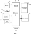
- FIG. 8 is a block diagram of a wireless charging transmitter 800, according to an exemplary embodiment.
- the device 800 may be a mobile phone, a computer, a digital broadcast terminal, a messaging device, a gaming console, a tablet, a medical device, exercise equipment, a personal digital assistant and the like.
- the device 800 may include one or more of the following components: a processing component 802, a memory 804, a power component 806, a multimedia component 808, an audio component 810, an Input/Output (I/O) interface 812, a sensor component 814, and a communication component 816.
- a processing component 802 a memory 804, a power component 806, a multimedia component 808, an audio component 810, an Input/Output (I/O) interface 812, a sensor component 814, and a communication component 816.
- the processing component 802 typically controls overall operations of the device 800, such as the operations associated with display, telephone calls, data communications, camera operations, and recording operations.
- the processing component 802 may include one or more processors 820 to execute instructions to perform all or part of the steps in the abovementioned method.
- the processing component 802 may include one or more modules which facilitate interaction between the processing component 802 and the other components.
- the processing component 802 may include a multimedia module to facilitate interaction between the multimedia component 808 and the processing component 802.
- the memory 804 is configured to store various types of data to support the operation of the device 800. Examples of such data include instructions for any application programs or methods operated on the device 800, contact data, phonebook data, messages, pictures, video, etc.
- the memory 804 may be implemented by any type of volatile or nonvolatile memory devices, or a combination thereof, such as a Static Random Access Memory (SRAM), an Electrically Erasable Programmable Read-Only Memory (EEPROM), an Erasable Programmable Read-Only Memory (EPROM), a Programmable Read-Only Memory (PROM), a Read-Only Memory (ROM), a magnetic memory, a flash memory, and a magnetic or optical disk.
- SRAM Static Random Access Memory
- EEPROM Electrically Erasable Programmable Read-Only Memory
- EPROM Erasable Programmable Read-Only Memory
- PROM Programmable Read-Only Memory
- ROM Read-Only Memory
- magnetic memory a magnetic memory
- flash memory and a magnetic or optical disk.
- the power component 806 provides power for various components of the device 800.
- the power component 806 may include a power management system, one or more power supplies, and other components associated with generation, management and distribution of power for the device 800.
- the multimedia component 808 includes a screen providing an output interface between the device 800 and a user.
- the screen may include a Liquid Crystal Display (LCD) and a Touch Panel (TP). If the screen includes the TP, the screen may be implemented as a touch screen to receive an input signal from the user.
- the TP includes one or more touch sensors to sense touches, swipes and orientations on the TP. The touch sensors may not only sense a boundary of a touch or swipe action but also detect a duration and pressure associated with the touch or swipe action.
- the multimedia component 808 includes a front camera and/or a rear camera.
- the front camera and/or the rear camera may receive external multimedia data when the device 800 is in an operation mode, such as a photographing mode or a video mode.
- an operation mode such as a photographing mode or a video mode.
- Each of the front camera and the rear camera may be a fixed optical lens system or have focusing and optical zooming capabilities.
- the audio component 810 is configured to output and/or input an audio signal.
- the audio component 810 includes a Microphone (MIC), and the MIC is configured to receive an external audio signal when the device 800 is in the operation mode, such as a call mode, a recording mode and a voice recognition mode.
- the received audio signal may further be stored in the memory 804 or sent through the communication component 816.
- the audio component 810 further includes a speaker configured to output the audio signal.
- the I/O interface 812 provides an interface between the processing component 802 and a peripheral interface module, and the peripheral interface module may be a keyboard, a click wheel, a button and the like.
- the button may include, but not limited to: a home button, a volume button, a starting button and a locking button.
- the sensor component 814 includes one or more sensors configured to provide status assessment in various aspects for the device 800. For instance, the sensor component 814 may detect an on/off status of the device 800 and relative positioning of components, such as a display and small keyboard of the device 800, and the sensor component 814 may further detect a change in a position of the device 800 or a component of the device 800, presence or absence of contact between the user and the device 800, orientation or acceleration/deceleration of the device 800 and a change in temperature of the device 800.
- the sensor component 814 may include a proximity sensor configured to detect presence of an object nearby without any physical contact.
- the sensor component 814 may also include a light sensor, such as a Complementary Metal Oxide Semiconductor (CMOS) or Charge Coupled Device (CCD) image sensor, configured for use in an imaging application.
- CMOS Complementary Metal Oxide Semiconductor
- CCD Charge Coupled Device
- the sensor component 814 may also include an acceleration sensor, a gyroscope sensor, a magnetic sensor, a pressure sensor or a temperature sensor.
- the communication component 816 is configured to facilitate wired or wireless communication between the device 800 and other equipment.
- the device 800 may access a communication-standard-based wireless network, such as a Wireless Fidelity (WiFi) network, a 2nd-Generation (2G) or 3rd-Generation (3G) network or a combination thereof.
- WiFi Wireless Fidelity
- 2G 2nd-Generation
- 3G 3rd-Generation
- the communication component 816 receives a broadcast signal or broadcast associated information from an external broadcast management system through a broadcast channel.
- the communication component 816 further includes a Near Field Communication (NFC) module to facilitate short-range communication.
- NFC Near Field Communication
- the NFC module may be implemented based on a Radio Frequency Identification (RFID) technology, an Infrared Data Association (IrDA) technology, an Ultra-WideBand (UWB) technology, a Bluetooth (BT) technology and another technology.
- RFID Radio Frequency Identification
- IrDA Infrared Data Association
- UWB Ultra-WideBand
- BT Bluetooth
- the device 800 may be implemented by one or more Application Specific Integrated Circuits (ASICs), Digital Signal Processors (DSPs), Digital Signal Processing Devices (DSPDs), Programmable Logic Devices (PLDs), Field Programmable Gate Arrays (FPGAs), controllers, micro-controllers, microprocessors or other electronic components, and is configured to execute the abovementioned method.
- ASICs Application Specific Integrated Circuits
- DSPs Digital Signal Processors
- DSPDs Digital Signal Processing Devices
- PLDs Programmable Logic Devices
- FPGAs Field Programmable Gate Arrays
- controllers micro-controllers, microprocessors or other electronic components, and is configured to execute the abovementioned method.
- a non-transitory computer-readable storage medium including an instruction such as the memory 804 including an instruction, and the instruction may be executed by the processor 820 of the device 800 to implement the abovementioned method.
- the non-transitory computer-readable storage medium may be a ROM, a Random Access Memory (RAM), a Compact Disc Read-Only Memory (CD-ROM), a magnetic tape, a floppy disc, an optical data storage device and the like.
Landscapes
- Engineering & Computer Science (AREA)
- Power Engineering (AREA)
- Computer Networks & Wireless Communication (AREA)
- Charge And Discharge Circuits For Batteries Or The Like (AREA)
- Telephone Function (AREA)
Abstract
Description
- The present disclosure generally relates to the technical field of wireless charging, and more specifically, to a method and a device for wireless charging, a wireless charging transmitter and a storage medium.
- In a related art, an electromagnetic-induction-based Wireless Power Consortium (SPC) standard and a magnetic resonance technology-based AirFuel Alliance (AFA) standard are adopted for mainstream wireless charging solutions. The AFA standard is a standard established by the AFA. Since a technology maturity of the AFA standard is too low to meet a commercial requirement, the WPC standard is adopted for all wireless charging solutions on the present market.
- As shown in
FIG. 1, FIG. 1 illustrates wireless charging solutions for products of mainstream mobile phone manufacturers (a company A, a company B, a company C and a company D). It can be seen that present wireless charging solutions of the mainstream mobile phone manufacturers are all WPC solutions and applied to short-distance wireless charging within 5mm between a transmitting device and a receiving device. With increasing extension of Internet of everything scenarios, long-distance wireless charging solutions have become more and more important. However, with remarkable improvement of the degree of freedom of long-distance wireless charging, charging efficiency is difficult to reach ideal charging efficiency that is required. - The present disclosure provides a method and a device for wireless charging, a wireless charging transmitter and a storage medium.
- According to a first aspect of embodiments of the present disclosure, there is provided a method for wireless charging, which may be applied to a wireless charging transmitter and include that:
- position-orientation information of a terminal for wireless charging based on a radio frequency signal transmitted by the wireless charging transmitter is acquired;
- whether the terminal is in a target charging state is determined based on the position-orientation information; and
- responsive to that it is determined that the terminal is not in the target charging state, first prompting information is output, herein the first prompting information is used to prompt an adjustment of the position-orientation information of the terminal.
- The technical solutions provided by embodiments of the present disclosure may have the following beneficial effects.
- In the embodiments of the present disclosure, the position-orientation information of the terminal for wireless charging based on the radio frequency signal transmitted by the wireless charging transmitter is acquired; whether the terminal is in the target charging state is determined based on the position-orientation information; and responsive to that it is determined that the terminal is not in the target charging state, prompting information for adjusting the position-orientation information of the terminal may be output to prompt a user to adjust the position-orientation of the terminal, so that subsequent adjustment of the terminal to a proper position-orientation for meeting a requirement that the terminal is in the target charging state and improving charging efficiency of the terminal is facilitated.
- Whether the terminal is in the target charging state is determined through the position-orientation information, and when the terminal is not in the target charging state, the position-orientation of the terminal is changed to improve the charging efficiency. Such a manner is easy to operate and implement, and a user experience is also greatly improved.
- In the solution, the operation that whether the terminal is in the target charging state is determined based on the position-orientation information may include that:
- charging efficiency corresponding to the position-orientation information is determined based on a predetermined correspondences between position-orientations of the terminal and charging efficiency;
- responsive to that the charging efficiency is within a preset charging efficiency range, it is determined that the terminal is in the target charging state; and
- responsive to that the charging efficiency is outside of the preset charging efficiency range, it is determined that the terminal is not in the target charging state.
- In the solution, the operation that responsive to that the charging efficiency is within the preset charging efficiency range, it is determined that the terminal is in the target charging state may include that:
- responsive to that the charging efficiency is maximum charging efficiency in the correspondences, it is determined that the terminal is in the target charging state.
- In the solution, the method may further include that:
- responsive to that the terminal is not in the target charging state, second prompting information is output based on the position-orientation information and a position-orientation of the terminal corresponding to charging efficiency within the preset charging efficiency range,
- the second prompting information is used to prompt a parameter for adjusting the position-orientation of the terminal, and the adjustment parameter includes at least one parameter of: a direction in which a position of the terminal is adjusted, a distance by which the position of the terminal is adjusted or an orientation of the terminal.
- In the solution, the method may further include that:
- responsive to that it is determined that the terminal is in the target charging state, third prompting information is output, herein the third prompting information is used to prompt that the terminal is in the target charging state.
- In the solution, the method may further include that:
- first receiving power returned by the terminal based on first transmitting power is received, herein the first transmitting power is power at which the radio frequency signal is transmitted by the wireless charging transmitter;
- first transmission efficiency is determined based on the first transmitting power and the first receiving power; and
- responsive to that it is determined that a difference between the first transmission efficiency and the maximum charging efficiency is less than a first threshold value, it is determined that the terminal is in the target charging state.
- In the solution, the position-orientation information includes at least one of position information or orientation information, herein the position information represents a distance between the terminal and the wireless charging transmitter, or a space distribution of the terminal; and the orientation information represents that the terminal is lying flat, vertical or at an angle with respect to the horizontal plane, or is orientation information or direction information of the terminal.
- According to a second aspect of the embodiments of the present disclosure, there is provided a device for wireless charging, which may include:
- an acquisition module, configured to acquire position-orientation information of a terminal for wireless charging based on a radio frequency signal transmitted by a wireless charging transmitter;
- a determination module, configured to determine, based on the position-orientation information, whether the terminal is in a target charging state; and
- a processing module, configured to, responsive to that it is determined that the terminal is not in the target charging state, output first prompting information, herein the first prompting information is used to prompt an adjustment of the position-orientation information of the terminal.
- In the solution, the determination module may include:
- a first determination unit, configured to determine, based on a predetermined correspondences between position-orientations of the terminal and charging efficiency, charging efficiency corresponding to the position-orientation information; and
- a second determination unit, configured to, responsive to that the charging efficiency is within a preset charging efficiency range, determine that the terminal is in the target charging state and, responsive to that the charging efficiency is outside of the preset charging efficiency range, determine that the terminal is not in the target charging state.
- In the solution, the second determination unit may be configured to, responsive to that the charging efficiency is maximum charging efficiency in the correspondences, determine that the terminal is in the target charging state.
- In the solution, the processing module may further be configured to, responsive to that the terminal is not in the target charging state, output second prompting information based on the position-orientation information and a position-orientation of the terminal corresponding to charging efficiency within the preset charging efficiency range,
- the second prompting information is used to prompt an adjustment parameter for adjusting the position-orientation of the terminal, and the adjustment parameter includes at least one parameter of a direction in which a position of the terminal is adjusted, a distance by which the position of the terminal is adjusted or an orientation of the terminal.
- In the solution, the processing module may be configured to, responsive to that it is determined that the terminal is in the target charging state, output third prompting information, herein the third prompting information is used to prompt that the terminal is in the target charging state.
- In the solution, the acquisition module may be configured to receive first receiving power returned by the terminal based on first transmitting power, herein the first transmitting power is power at which the radio frequency signal is transmitted by the wireless charging transmitter; and
- the determination module may further include:
- a third determination unit, configured to determine first transmission efficiency based on the first transmitting power and the first receiving power, and
- the second determination unit, responsive to that it is determined that a difference between the first transmission efficiency and the maximum charging efficiency is less than a first threshold value, determine that the terminal is in the target charging state.
- According to a third aspect of embodiments of the present disclosure, there is provided another wireless charging transmitter, which may include:
- a processor; and
- memory storing instructions for execution by the processor,
- wherein the processor may be configured to run computer service to implement the method for wireless charging of any embodiment of the present disclosure.
- According to a fourth aspect of the embodiments of the present disclosure, there is provided a non-transitory computer-readable storage medium having stored therein executable program that when being executed by a processor, implement the method for wireless charging of any embodiment of the present disclosure.It is to be understood that the above general descriptions and detailed descriptions below are only exemplary and explanatory and not intended to limit the present disclosure.
- The accompanying drawings, which are incorporated in and constitute a part of this specification, illustrate embodiments consistent with the present disclosure and, together with the description, serve to explain the principles of the present disclosure.
-
FIG. 1 illustrates wireless charging solutions for products of mainstream mobile phone manufacturers. -
FIG. 2 is a flow chart showing a method for wireless charging, according to an exemplary embodiment. -
FIG. 3 is a flow chart showing another method for wireless charging, according to an exemplary embodiment. -
FIG. 4 is a block diagram of a wireless charging transmitter, according to an exemplary embodiment. -
FIG. 5 is a block diagram of a terminal, according to an exemplary embodiment. -
FIG. 6 is a flow chart showing another method for wireless charging, according to an exemplary embodiment. -
FIG. 7 is a block diagram of a device for wireless charging, according to an exemplary embodiment. -
FIG. 8 is a block diagram of another device for wireless charging, according to an exemplary embodiment. - Reference will now be made in detail to exemplary embodiments, examples of which are illustrated in the accompanying drawings. The following description refers to the accompanying drawings in which the same numbers in different drawings represent the same or similar elements unless otherwise represented. The implementations set forth in the following description of exemplary embodiments do not represent all implementations consistent with the present disclosure. Instead, they are merely examples of apparatuses and methods consistent with aspects related to the present disclosure as recited in the appended claims.
-
FIG. 2 is a flow chart showing a method for wireless charging, according to an exemplary embodiment. As shown inFIG. 2 , the method for wireless charging is applied to a wireless charging transmitter and includes the following steps. - In
block 11, position-orientation information of a terminal for wireless charging based on a radio frequency signal transmitted by the wireless charging transmitter is acquired. - In
block 12, whether the terminal is in a target charging state is determined based on the position-orientation information. - In
block 13, responsive to that it is determined that the terminal is not in the target charging state, first prompting information is output, and the first prompting information is used to prompt an adjustment of the position-orientation information of the terminal. - In the embodiment of the present disclosure, the wireless charging transmitter may be any electronic device capable of transmitting a radio frequency signal. The terminal may be any electronic device capable of receiving a radio frequency signal. For example, the terminal may be a mobile communication device, a Bluetooth earphone, a smart watch or band, or a notebook computer, etc.
- Herein, the position-orientation information includes position information and/or orientation information.
- Herein, the position information may be a distance between the terminal and the wireless charging transmitter, or the position information may also be a space distribution of the terminal. For example, in an office, a terminal is 5m away from a door and 3m away from a window.
- The orientation information may be that the terminal is lying flat, vertical or at a certain angle with respect to the horizontal plane, or the orientation information may also be orientation information or direction information of the terminal. For example, the terminal faces 45° southwest. For another example, the terminal faces a direction opposite to a direction in which the wireless charging transmitter transmits the radio frequency signal. In a word, an angle between the terminal and a transmitting direction of the radio frequency signal may be determined based on the position-orientation information.
- In some embodiments, as shown in
FIG. 3 , S12 includes the following steps. - In
block 121, charging efficiency corresponding to the position-orientation information is determined based on predetermined correspondences between position-orientations of the terminal and charging efficiencies. - In
block 122a, responsive to that the charging efficiency is within a preset charging efficiency range, it is determined that the terminal is in the target charging state. - In
block 122b, responsive to that the charging efficiency is outside of the preset charging efficiency range, it is determined that the terminal is not in the target charging state. - Herein, the correspondences between the position-orientations of the terminal and the charging efficiencies may be in form of a table or a list, or may be in form of an array, etc. In a practical application, the position-orientation information includes a distance and an angle. Herein, specific implementation of the correspondences is only required to meet such a form that {distance, angle} corresponds to charging efficiency one to one, and there are no limits made herein.
- For example, Table 1 provides the correspondences between the position-orientations of the terminal and charging efficiencies. The correspondences are in the table form. Distances in each position-orientation information of the terminal include D1, D2, D3, ..., Dn, and angles in each position-orientation information of the terminal include θ1, θ2, θ3, ..., θn. The position-orientation information (D1, θ1), (D1, θ2), ..., (D1, θn), (D2, θ1), (D2, θ2), ..., (D2, θn), (D3, θ1), ..., (Dn, θn) of the terminal correspond to charging efficiency P11, P12, ..., P1n, P21, P22, ..., P2n, P31, ..., Pnn respectively, specifically as shown in Table 1.

- Herein, preset charging efficiency may be charging efficiency greater than or equal to a second threshold value.
- For example, if the second threshold value is 30%, the preset charging efficiency is a value greater than or equal to 30%. When it is obtained by querying based on the correspondences that present charging efficiency corresponding to the position-orientation of the terminal is greater than 30%, it is determined that the terminal is in the target charging state; and when it is obtained by querying that the present charging efficiency corresponding to the position-orientation of the terminal is less than 30%, it is determined that the terminal is not in the target charging state.
- Herein, the preset charging efficiency may be charging efficiency at a relatively high charging efficiency rank.
- For example, if the charging efficiency is 0% to 60%, the preset charging efficiency may be 55% to 60%.
- Accordingly, in the embodiment, the correspondences between the position-orientations of the terminal and charging efficiencies may be established in advance; the present charging efficiency corresponding to the position-orientation information is determined based on the acquired position-orientation information of the terminal and the correspondences; whether the present charging efficiency is charging efficiency corresponding to the target charging state is determined, if the present charging efficiency is charging efficiency corresponding to the target charging state, it is determined that the terminal is in the target charging state, and if the present charging efficiency is not charging efficiency corresponding to the target charging state, it is determined that the terminal is not in the target charging state. Therefore, whether the terminal is in the relatively ideal target charging state may be accurately determined based on the correspondences. Moreover, such a manner is simple and easy to implement.
- In other embodiments,
S 122b includes that: - responsive to that the charging efficiency is maximum charging efficiency in the correspondences, it is determined that the terminal is in the target charging state.
- For example, if the charging efficiency in the correspondences is 0% to 60%, the maximum charging efficiency is 60%.
- In the embodiment, each charging efficiency in the correspondences may be compared to determine the maximum charging efficiency. Then, the present charging efficiency corresponding to the position-orientation information of the terminal is queried based on the correspondences. If it is determined that the charging efficiency is the maximum charging efficiency, it is determined that the terminal is in the target charging state, and if NO, it is determined that the terminal is not in the target charging state. Therefore, in the embodiment, the more ideal target charging state of the terminal is further determined to further improve charging efficiency of the terminal when the position-orientation of the terminal is subsequently adjusted based on position-orientation information corresponding to the maximum charging efficiency.
- Herein, in an implementation of S13, if it is determined that the terminal is not in the target charging state, the first prompting information is displayed on a display screen of the wireless charging transmitter. For example, prompting information such as "the terminal is not in the target charging state, please timely adjust the position-orientation information of the terminal" is displayed on the display screen of the wireless charging transmitter.
- In another implementation of S13, if it is determined that the terminal is not in the target charging state, a first prompting voice is produced. Herein, the first prompting information includes the first prompting voice. Herein, a first voice module may be arranged in the wireless charging transmitter, and a prompting voice that "the terminal is not in the target charging state, please adjust the position-orientation information of the terminal" is produced based on the voice module.
- In an embodiment, the method further includes that: the first prompting information is sent to the terminal, the first prompting information is used to be displayed by the terminal based on a display screen of the terminal. In such a manner, a user may timely see the prompting information and timely adjust the position-orientation of the terminal, so that the charging efficiency of the terminal is improved, and meanwhile, great convenient is brought to the user.
- In the embodiment of the present disclosure, the position-orientation information of the terminal may be acquired; whether the terminal is in the target charging state is determined based on the position-orientation information; and if the terminal is not in the target charging state, prompting information for adjusting the position-orientation information of the terminal is output to prompt the user to adjust the position-orientation of the terminal, so that subsequent adjustment of the terminal to a proper position-orientation for meeting a requirement that the terminal is in the target charging state and improving charging efficiency of the terminal is facilitated.
- Further, the charging efficiency corresponding to the position-orientation is determined via the predetermined correspondences between the position-orientations of the terminal and the charging efficiencies, and whether the terminal is in the target charging state is determined based on whether the charging efficiency is within the preset charging efficiency range, so that the ideal target charging state of the terminal may be accurately determined.
- Furthermore, whether the charging efficiency is the maximum charging efficiency in the correspondences is determined to determine whether the terminal with the position-orientation information is in the target charging state, so that the more ideal charging state may further be determined to further improve the charging efficiency of the terminal when the position-orientation of the terminal is subsequently adjusted based on the position-orientation information corresponding to the maximum charging efficiency.
- Whether the terminal is in the target charging state is determined via the position-orientation information, and if the terminal is not in the target charging state, the position-orientation of the terminal is changed to improve the charging efficiency. Such a manner is easy to operate and implement, and a user experience is also greatly improved.
- Referring to
FIG. 3 again, in some embodiments, the method further includes the following step. - In
block 14, responsive to that the terminal is not in the target charging state, second prompting information is output based on the position-orientation information and a position-orientation of the terminal corresponding to charging efficiency within the preset charging efficiency range, - the second prompting information is used to prompt an adjustment parameter for adjusting the position-orientation of the terminal, and the adjustment parameter includes at least one parameter of: a direction in which a position of the terminal is adjusted, a distance by which the position of the terminal is adjusted or an orientation of the terminal.
- Herein, charging efficiency corresponding to the target charging state may be the preset charging efficiency; or, the charging efficiency corresponding to the target charging state may also be the maximum charging efficiency in the correspondences.
- Herein, a distance by which the position of the terminal is adjusted may be a distance corresponding to the preset charging efficiency. For example, in a practical application, a present position of the terminal is 7m far away from the wireless charging transmitter, and the distance corresponding to the preset charging efficiency is 5m to 6m far away from the wireless charging transmitter. In such case, a distance by which the position of the terminal is adjusted may be 1m to 2m.
- Herein, a distance by which the position of the terminal is adjusted may be a distance corresponding to the maximum charging efficiency. For example, in a practical application, the present position of the terminal is 7m far away from the wireless charging transmitter, and the distance corresponding to the maximum charging efficiency is 5.5m far away from the wireless charging transmitter. In such case, a distance by which the position of the terminal is adjusted can be 7-5.5=1.5m.
- It can be understood that the direction in which a position of the terminal is adjusted or the orientation of the position of the terminal may be considered as adjusting the angle of the terminal in a practical application. Orientation in which a position of the terminal is adjusted is adjusted based on a first angle, and a direction in which a position of the terminal is adjusted is adjusted based on a second angle, and the first angle is greater than the second angle.
- Herein, an angle by which the terminal is adjusted may be the distance corresponding to the preset charging efficiency. For example, in a practical application, a present angle between the terminal and the radio frequency signal transmitted by the wireless charging transmitter is 10°, and an angle, corresponding to the preset charging efficiency, with the radio frequency signal transmitted by the wireless charging transmitter is 15° to 20°. In such case, an angle by which the terminal is adjusted is 5° to 10°.
- Herein, the angle by which the terminal is adjusted may be the distance corresponding to the maximum charging efficiency. For example, in a practical application, the present angle between the terminal and the radio frequency signal transmitted by the wireless charging transmitter is 10°, and an angle, corresponding to the maximum charging efficiency, with transmission of the radio frequency signal by the wireless charging transmitter is 18°. In such case, an angle by which the terminal is adjusted is 8°.
- Here, an implementation of the operation that the second prompting information is output is that: the second prompting information is displayed by use of the display screen of the wireless charging transmitter. For example, prompting information such as "the terminal is not in the target charging state, please adjust the terminal to be 1m far away from the wireless charging transmitter" or "please adjust the terminal to be deflected 5° southwestwards" is displayed on the display screen.
- Herein, another implementation of the operation that the second prompting information is output is that: a second prompting voice is produced. For example, a prompting voice such as "the terminal is not in the target charging state, please adjust the terminal to be 1m far away from the wireless charging transmitter" or "please adjust the terminal to be deflected 5° southwestwards" is produced by use of the voice module of the wireless charging transmitter.
- In some other embodiments, the method further includes that: the second prompting information is sent to the terminal. The second prompting information is displayed by the terminal based on the display screen of the terminal. Therefore, the user may conveniently see the adjustment parameter which is suggested to adjust position information of the terminal on the terminal, and great convenience is brought to operations of the user.
- In the embodiment of the present disclosure, the difference between the position-orientation of the terminal corresponding to the charging efficiency within the preset charging efficiency range and the position-orientation information may be determined, and a prompt about adjustment of parameter information is made based on the difference, so that the user may favorably adjust the position-orientation of the terminal based on the prompting information. For example, the distance between the terminal and the wireless charging transmitter is adjusted, and/or the angle between the terminal and the radio frequency signal is adjusted, so that the position-orientation of the terminal may be adjusted from many aspects, and adjustment of the position-orientation of the terminal for meeting the requirement that the terminal is in the target charging state and improving the charging efficiency of the terminal is facilitated.
- Referring to
FIG. 3 again, in some other embodiments, the method further includes the following step. - In
block 15, responsive to that it is determined that the terminal is in the target charging state, third prompting information is output, and the third prompting information is used to prompt that the terminal is in the target charging state. - Herein, the operation that the third prompting information is output may also include at least one of the following operations: the third prompting information is displayed by use of the display screen of the wireless charging transmitter; and a third prompting voice is produced by use of the voice module of the wireless charging transmitter.
- For example, prompting information such as "the terminal is in the target charging state" is displayed on the display screen of the wireless charging transmitter.
- In some other embodiments, the method further includes that: the third prompting information is sent to the terminal, and the third prompting information is displayed by the terminal based on the display screen of the terminal. Therefore, the user may conveniently see the prompting information on the terminal.
- In the embodiment of the present disclosure, responsive to that it is determined that the terminal is in the target charging state, the third prompting information may be output to prompt the user that the terminal is charged at a relatively ideal position-orientation and the position-orientation of the terminal is not required to be adjusted.
- In some embodiments, the method further includes that:
- first receiving power returned by the terminal based on first transmitting power is received, and the first transmitting power is power at which the radio frequency signal is transmitted by the wireless charging transmitter;
- first transmission efficiency is determined based on the first transmitting power and the first receiving power; and
- responsive to that it is determined that a difference between the first transmission efficiency and the maximum charging efficiency is less than a first threshold value, it is determined that the terminal is in the target charging state.
- In some other embodiments, the operation that: responsive to that it is determined that the difference between the first transmission efficiency and the maximum charging efficiency is less than the first threshold value, it is determined that the terminal is in the target charging state, may be implemented as follows: responsive to that it is determined that the first transmission efficiency is within the preset charging efficiency range, it is determined that the terminal is in the target charging state.
- In some other embodiments, the method further includes that:
- responsive to that it is determined that the difference between the first transmission efficiency and the maximum charging efficiency is greater than or equal to the first threshold value, it is determined that the terminal is not in the target charging state;
- or,
- responsive to that it is determined that the first transmission efficiency is outside of the preset charging efficiency range, it is determined that the terminal is not in the target charging state.
- In a practical application, it may be considered that charging efficiency calculated based on the position-orientation information in the abovementioned embodiments is the first transmission efficiency in the embodiments.
- In the embodiment of the present disclosure, the first transmission efficiency may directly be compared with the preset charging efficiency to determine whether the terminal is in the target charging state. Another manner for determining the target charging state is provided, and the manner is simple and easy to implement.
- Exemplarily, as shown in
FIG. 4 , a block diagram of a wireless charging transmitter shaped like a desk lamp is provided. Thewireless charging transmitter 400 includes: a supportingbody 401, adisplay screen 404 and at least one firstradio frequency antenna 405 which are placed on an outer surface of the supporting body; - a
base 402, provided with an receiving cavity; and -
support rods 403, one end of eachsupport rod 403 being connected with thebase 402 and the other end being connected with the supportingbody 401, to support the supportingbody 401. - In the example, the wireless charging transmitter may be designed into a state like a desk lamp, and then the wireless charging transmitter may be placed on a desk or an office table, etc. Therefore, a user may conveniently view data displayed on the display screen, and convenience is brought to the user. Moreover, in such a design of the wireless charging transmitter in the state like a desk lamp, a light-emitting component may further be arranged in the wireless charging transmitter, thereby endowing the wireless charging transmitter with a basic function of a desk lamp.
- Of course, in another embodiments, the wireless charging transmitter may be placed at any other position, for example, placed on a ceiling of an office or suspended on a door.
- Exemplarily, as shown in
FIG. 5 , a block diagram of a terminal is provided. The terminal 500 includes: - a
housing 501, including afront housing 5011 and arear housing 5012; and - at least one second
radio frequency antenna 502, positioned on an outer surface of therear housing 5012. - In the embodiment of the present disclosure, for avoiding influence on a screen-to-body ratio of a screen of the terminal, the at least one second
radio frequency antenna 502 may be arranged on therear housing 5012 of the mobile phone and may specifically be arranged on the outer surface of therear housing 5012. - In the example, the at least one second
radio frequency antenna 502 may be arranged in form of an antenna array. Therefore, a size and a direction of a radiation field are changed in form of the antenna array to maximally receive a radio frequency signal. - In the example, the at least one second
radio frequency antenna 502 is arranged on the outer surface of therear housing 5012, so that the influence on the screen-to-body ratio of the screen of the terminal may be avoided; and moreover, the at least one secondradio frequency antenna 502 is arranged on the outer surface of therear housing 5012, so that influence on reception of the radio frequency signal may be avoided no matter which material the housing of the terminal is made of. - In a practical application, for overall charging efficiency of a terminal, besides the abovementioned first transmitting power, internal power conversion conditions of a wireless charging transmitter and the terminal may further be considered. A charging efficiency calculation method for a wireless charging system is also provided below. The overall charging efficiency is determined based on first transmission efficiency of a transceiver antenna, second transmission efficiency of the wireless charging transmitter and third transmission efficiency of the terminal. The calculation method for the overall charging efficiency includes the following steps.
- In (1), the first transmission efficiency of the transceiver antenna is calculated.
- Herein, the first transmission efficiency is transmission efficiency between the wireless charging transmitter and the terminal. Specifically, based on a corrected Friis transmission formula, the first transmission efficiency is

where G t is a transmitting gain of the wireless charging transmitter, G r is a receiving gain of the terminal, λ is a wavelength, D is a transmission distance, the transmission distance is a distance between the wireless charging transmitter and the terminal, Lt is joint loss of wireless connection, and G r(θ r ϕ r) is loss produced by an alignment error of a receiving node. - It is to be noted that, when the distance between the wireless charging transmitter and the terminal is 0.707m to 1.082m, wireless charging is implemented in a near field region.
- Exemplarily, if the terminal is positioned at a horizontal radius 0.5m, namely the distance between the wireless charging transmitter and the terminal is D=0.707m, G t and G r are 26.4dBi and 20.65dBi, λ is 0.03125m, Lt is 0.3dB, the loss G r(θ r ϕ r) produced by the alignment error of the receiving node is 0.2, and η T-R =55.9% is calculated.
- Therefore, when the terminal is positioned at the horizontal radius 0.5m, optimal transmission efficiency between a first transmitting antenna of the wireless charging transmitter and a second transmitting antenna of the terminal is 55.9%.
- In (2), the second transmission efficiency of the wireless charging transmitter is calculated.
- Herein, the second transmission efficiency is overall efficiency of a transmitting channel of the wireless charging transmitter. Specifically, the second transmission efficiency is

where PT is total output power of the phased array transmitting channel, and PDIS is total direct current power consumption of the phased array transmitting channel. - Exemplarily, PDIS is calculated as follows.
- Positive voltage (drain voltage) power consumption of power amplifiers of 24 transmitting channel modules is considered. Specifically, a 6-path transmitting channel module includes 6 power amplifier chips. If the power amplifier chip is WFD090100-P28, the power amplifier chip is powered based on a +8V voltage and additional efficiency of the power amplifier chip is about 43%, it may be calculated that power consumption of each chip is about 1.68W and a current is about 0.21A, and power consumption of each 6-path transmitting channel module is about 1.68W×6=10.08W. Therefore, total power consumption of the 24 transmitting channel modules is about 10.08W×24=241.92W. If a maximum duty ratio of the transmitting channel module during work is 45%, practical power consumption of the 24 transmitting channel modules is 241.92W×45%=108.86W.
- Positive voltage (drain voltage) power consumption of 2 power amplifier network modules is considered. Specifically, a power amplifier network module includes 6 power amplifier chips WFD090100-P28HMC451 and a driving and power amplifier chip HMC451. It may be calculated that power consumption of the driving and power amplifier chip HMC451 is 8V∗120mA=0.96W. Therefore, power consumption of a power amplifier network module is 10.08+0.96W=11.04W, and power consumption of the 2 power amplifier network modules is 11.04W×2=22.08W. If a maximum duty ratio of the power amplifier network module during work is 45%, practical power consumption of the 2 power amplifier network modules is 22.08W×40%=9.936W.
- Power consumption of a frequency source power divider module and a power amplifier negative voltage module is considered. Specifically, a current of the frequency source power divider module is about 35mA+350mA+65mA=450mA, and in such case, total power consumption of the frequency source power divider module is about 450mA×8V=3.6W. If the power amplifier negative voltage module includes 156 power amplifier chips, and each power amplifier chip is supplied based on a -5V voltage and a 5mA current, it is calculated that total power consumption of the power amplifier negative voltage module is 5V×5mA×156=3.9W. If efficiency of the power amplifier chip is 80%, practical power consumption of the power amplifier negative voltage module is 3.9W/0.8=4.875W.
- It is calculated that PDIS under the duty ratio of 45% is 108.86W +9.936W +4.875W=123.671W.
- Considering that a practical output voltage of a low-frequency power line is 8.2V and conversion efficiency is 8V/8.2V=97.56%, PDIS is practically 123.671W/97.56%=126.764W.
PT is calculated as follows. - Output of a single-channel power amplifier is 28.7dBm, and considering power reduction caused by joint loss, other loss and temperature rises, the output at a normal temperature is 28dBm (0.63W).
- It is calculated that PT under the duty ratio of 45% is 0.63W×144×45%=40.82W.
- It is calculated that the second transmission efficiency under the duty ratio of 45% is η DC-MW =0.63W×144×45%/126.764W=32.21%.
- In (3), the third transmission efficiency of the terminal is calculated.
- Herein, the third transmission efficiency is conversion efficiency of a rectified current of the terminal. Specifically, the third transmission efficiency is

where PDC is output power of a rectifier circuit, and PMW is input power consumption of the rectifier circuit. - If a ratio of the output power to input power of the rectifier circuit is 40%,

- Through the operations of (1), (2) and (3), the overall charging efficiency of the whole wireless charging transmitter-terminal system may be calculated to be ηALL =ηDC-MW •η T-R •η MW-DC =32.21%×55.9%×40%=7.2%.
- It can be understood that the first transmission efficiency is practically determined based on position-orientation information (including a distance with the wireless charging transmitter and an angle of the terminal) of the terminal, and is the charging efficiency in the abovementioned embodiment. In another embodiment, if the charging efficiency of the terminal is further required to be improved, the second transmission efficiency and/or the third transmission efficiency may also be changed. For example, at least one of the total output power of the phased array transmitting channel and the output power of the rectifier circuit may be improved. There are no limits made herein.
- Example 1
-
FIG. 6 is a flow chart showing a method for wireless charging, according to an exemplary embodiment. As shown inFIG. 6 , the method for wireless charging is applied to a wireless charging system, the wireless charging system including a wireless charging transmitter and a mobile phone. The method includes the following steps. - In
block 201, a charging efficiency truth table is established, and a first distance and first orientation information corresponding to maximum charging efficiency are determined. - Optionally, the wireless charging transmitter establishes the charging efficiency truth table based on each position-orientation of the terminal and corresponding charging efficiency, and determines the first distance and first orientation information corresponding to the maximum charging efficiency based on the charging efficiency truth table.
- Herein, in an embodiment, the charging efficiency corresponding to each position-orientation of the terminal may be determined based on the first transmission efficiency

- In
block 202, the mobile phone starts to be charged. - In
block 203, a second distance and second orientation information of the mobile phone are detected. - Optionally, the wireless charging transmitter detects the second distance and second orientation information of the mobile phone.
- Herein, the second distance and the second orientation information may be determined based on position information, received by the wireless charging transmitter, of the terminal.
- In
block 204, whether the mobile phone corresponds to the first distance and first orientation information corresponding to the maximum charging efficiency is judged. - Optionally, the wireless charging transmitter compares the first distance and the second distance to determine whether the second distance is the same as the first distance, and compares the first orientation information and the second orientation information to determine whether the second orientation information is the same as the first orientation information.
- In an optional embodiment, if the first distance is different from the second distance, a distance parameter for adjusting is determined based on the first distance and the second distance; and/or, if the first orientation information is different from the second orientation information, an angle parameter for adjusting is determined based on the first orientation information and the second orientation information.
- In block 205, first prompting information is displayed via a display screen, the first prompting information is used to prompt that the mobile phone is not in a target charging state and prompt to adjust the distance of the mobile phone as a third distance and/or a orientation of the mobile phone as a third angle.
- Optionally, the wireless charging transmitter displays the first prompting information via the display screen, the first prompting information is used to prompt that the mobile phone is not in the target charging state and suggest to adjust the distance of the mobile phone as the third distance and/or the orientation of the mobile phone as the third angle.
- In
block 206, the first prompting information is received, and the first prompting information is displayed on a display screen of the mobile phone. - Optionally, the mobile phone receives the first prompting information and displays the first prompting information on the display screen of the mobile phone. Specifically, prompting information that "the mobile phone is not in the target charging state, and it is suggested to adjust the distance of the mobile phone as the third distance and/or the orientation of the mobile phone as the third angle" is displayed.
- In block 207, the first distance and first position-orientation information of the mobile phone are adjusted based on the first prompting information.
- Herein, a user may adjust the first distance and first orientation information of the mobile phone based on the first prompting information in block 207. Specifically, the distance of the mobile phone is adjusted by the third distance to reach the first distance, and orientation information of the mobile phone is adjusted by the third angle to achieve an orientation corresponding to the first orientation information.
- In block 208, third prompting information is displayed via the display screen, the third prompting information is prompting information used to prompt that the mobile phone is in the target charging state.
- Optionally, the wireless charging transmitter displays the third prompting information that the mobile phone is in the target charging state via the display screen of the wireless charging transmitter.
- In
block 209, a position and orientation of the mobile phone are stopped to be adjusted. - In the embodiment of the present disclosure, the charging efficiency truth table is established, the distance and orientation corresponding to the maximum charging efficiency are determined, whether the mobile phone is in the target charging state is determined based on whether a present distance and orientation for charging of the mobile phone are the distance and orientation corresponding to the maximum charging efficiency, and if NO, the distance and orientation of the mobile phone are adjusted to the distance and orientation corresponding to the maximum charging efficiency, so that charging efficiency of the mobile phone is improved.
- The distance and orientation of the terminal are changed to improve the charging efficiency. Such a manner is easy to operate and implement, and a user experience is also greatly improved.
-
FIG. 7 is a block diagram of a device for wireless charging, according to an example. Referring toFIG. 7 , the device includes: - an
acquisition module 71, configured to acquire position-orientation information of a terminal for wireless charging based on a radio frequency signal transmitted by a wireless charging transmitter; - a
determination module 72, configured to determine, based on the position-orientation information, whether the terminal is in a target charging state ; and - a
processing module 73, configured to, responsive to that it is determined that the terminal is not in the target charging state, output first prompting information, the first prompting information is used to prompt an adjustment of the position-orientation information of the terminal. - In some embodiments, the
determination module 72 includes: - a
first determination unit 721, configured to determine, based on predetermined correspondences between position-orientations of the terminal and charging efficiency, charging efficiency corresponding to the position-orientation information; and - a
second determination unit 722, configured to, responsive to that the charging efficiency is within a preset charging efficiency range, determine that the terminal is in the target charging state and, responsive to that the charging efficiency is outside of the preset charging efficiency range, determine that the terminal is not in the target charging state. - In some embodiments, the
second determination unit 722 is configured to, responsive to that the charging efficiency is maximum charging efficiency in the correspondences, determine that the terminal is in the target charging state. - In some embodiments, the
processing module 73 is further configured to, responsive to that the terminal is not in the target charging state, output second prompting information based the position-orientation information and a position-orientation of the terminal corresponding to charging efficiency within the preset charging efficiency range,
the second prompting information is used to prompt an adjustment parameter for adjusting the position-orientation of the terminal and the adjustment parameter includes at least one parameter of: a direction in which a position of the terminal is adjusted, a distance by which the position of the terminal is adjusted or an orientation of the terminal. - In some embodiments, the
processing module 73 is configured to, responsive to that it is determined that the terminal is in the target charging state, output third prompting information, and the third prompting information is used to prompt that the terminal is in the target charging state. - In some embodiments, the
acquisition module 71 is configured to receive first receiving power returned by the terminal based on first transmitting power, and the first transmitting power is power at which the radio frequency signal is transmitted by the wireless charging transmitter; and
thedetermination module 72 further includes:
athird determination unit 723, configured to determine first transmission efficiency based on the first transmitting power and the first receiving power, and
thesecond determination unit 722, responsive to that it is determined that a difference between the first transmission efficiency and the maximum charging efficiency is less than a first threshold value, determine that the terminal is in the target charging state. - With respect to the device in the above embodiment, the specific manners for performing operations for individual modules therein have been described in detail in the embodiment regarding the method, which will not be elaborated herein.
- An embodiment of the present disclosure also provides a wireless charging transmitter, which includes: a processor; and
a memory configured to store processor-executable instructions,
wherein the processor is configured to run computer service to implement the charging method of any abovementioned embodiment. - The memory may include any type of storage medium, and the storage medium is a non-transitory computer storage medium and may keep information in a communication device after a power failure of the communication device.
- The processor may be connected with the memory through a bus and the like, and is configured to read an executable program stored in the memory to implement, for example, at least one of the methods shown in
FIG. 2 ,FIG. 3 andFIG. 6 . - An embodiment of the present disclosure also provides a non-transitory computer-readable storage medium having stored therein an executable program that when being executed by a processor, implement the method for wireless charging of any abovementioned embodiment, for example, implementing at least one of the methods shown in
FIG. 2 ,FIG. 3 andFIG. 6 . - With respect to the device in the above embodiment, the specific manners for performing operations for individual modules therein have been described in detail in the embodiment regarding the method, which will not be elaborated herein.
-
FIG. 8 is a block diagram of awireless charging transmitter 800, according to an exemplary embodiment. For example, thedevice 800 may be a mobile phone, a computer, a digital broadcast terminal, a messaging device, a gaming console, a tablet, a medical device, exercise equipment, a personal digital assistant and the like. - Referring to
FIG. 8 , thedevice 800 may include one or more of the following components: aprocessing component 802, amemory 804, apower component 806, amultimedia component 808, anaudio component 810, an Input/Output (I/O)interface 812, asensor component 814, and acommunication component 816. - The
processing component 802 typically controls overall operations of thedevice 800, such as the operations associated with display, telephone calls, data communications, camera operations, and recording operations. Theprocessing component 802 may include one ormore processors 820 to execute instructions to perform all or part of the steps in the abovementioned method. Moreover, theprocessing component 802 may include one or more modules which facilitate interaction between theprocessing component 802 and the other components. For instance, theprocessing component 802 may include a multimedia module to facilitate interaction between themultimedia component 808 and theprocessing component 802. - The
memory 804 is configured to store various types of data to support the operation of thedevice 800. Examples of such data include instructions for any application programs or methods operated on thedevice 800, contact data, phonebook data, messages, pictures, video, etc. Thememory 804 may be implemented by any type of volatile or nonvolatile memory devices, or a combination thereof, such as a Static Random Access Memory (SRAM), an Electrically Erasable Programmable Read-Only Memory (EEPROM), an Erasable Programmable Read-Only Memory (EPROM), a Programmable Read-Only Memory (PROM), a Read-Only Memory (ROM), a magnetic memory, a flash memory, and a magnetic or optical disk. - The
power component 806 provides power for various components of thedevice 800. Thepower component 806 may include a power management system, one or more power supplies, and other components associated with generation, management and distribution of power for thedevice 800. - The
multimedia component 808 includes a screen providing an output interface between thedevice 800 and a user. In some embodiments, the screen may include a Liquid Crystal Display (LCD) and a Touch Panel (TP). If the screen includes the TP, the screen may be implemented as a touch screen to receive an input signal from the user. The TP includes one or more touch sensors to sense touches, swipes and orientations on the TP. The touch sensors may not only sense a boundary of a touch or swipe action but also detect a duration and pressure associated with the touch or swipe action. In some embodiments, themultimedia component 808 includes a front camera and/or a rear camera. The front camera and/or the rear camera may receive external multimedia data when thedevice 800 is in an operation mode, such as a photographing mode or a video mode. Each of the front camera and the rear camera may be a fixed optical lens system or have focusing and optical zooming capabilities. - The
audio component 810 is configured to output and/or input an audio signal. For example, theaudio component 810 includes a Microphone (MIC), and the MIC is configured to receive an external audio signal when thedevice 800 is in the operation mode, such as a call mode, a recording mode and a voice recognition mode. The received audio signal may further be stored in thememory 804 or sent through thecommunication component 816. In some embodiments, theaudio component 810 further includes a speaker configured to output the audio signal. - The I/
O interface 812 provides an interface between theprocessing component 802 and a peripheral interface module, and the peripheral interface module may be a keyboard, a click wheel, a button and the like. The button may include, but not limited to: a home button, a volume button, a starting button and a locking button. - The
sensor component 814 includes one or more sensors configured to provide status assessment in various aspects for thedevice 800. For instance, thesensor component 814 may detect an on/off status of thedevice 800 and relative positioning of components, such as a display and small keyboard of thedevice 800, and thesensor component 814 may further detect a change in a position of thedevice 800 or a component of thedevice 800, presence or absence of contact between the user and thedevice 800, orientation or acceleration/deceleration of thedevice 800 and a change in temperature of thedevice 800. Thesensor component 814 may include a proximity sensor configured to detect presence of an object nearby without any physical contact. Thesensor component 814 may also include a light sensor, such as a Complementary Metal Oxide Semiconductor (CMOS) or Charge Coupled Device (CCD) image sensor, configured for use in an imaging application. In some embodiments, thesensor component 814 may also include an acceleration sensor, a gyroscope sensor, a magnetic sensor, a pressure sensor or a temperature sensor. - The
communication component 816 is configured to facilitate wired or wireless communication between thedevice 800 and other equipment. Thedevice 800 may access a communication-standard-based wireless network, such as a Wireless Fidelity (WiFi) network, a 2nd-Generation (2G) or 3rd-Generation (3G) network or a combination thereof. In an exemplary embodiment, thecommunication component 816 receives a broadcast signal or broadcast associated information from an external broadcast management system through a broadcast channel. In an exemplary embodiment, thecommunication component 816 further includes a Near Field Communication (NFC) module to facilitate short-range communication. For example, the NFC module may be implemented based on a Radio Frequency Identification (RFID) technology, an Infrared Data Association (IrDA) technology, an Ultra-WideBand (UWB) technology, a Bluetooth (BT) technology and another technology. - In an exemplary embodiment, the
device 800 may be implemented by one or more Application Specific Integrated Circuits (ASICs), Digital Signal Processors (DSPs), Digital Signal Processing Devices (DSPDs), Programmable Logic Devices (PLDs), Field Programmable Gate Arrays (FPGAs), controllers, micro-controllers, microprocessors or other electronic components, and is configured to execute the abovementioned method. - In an exemplary embodiment, there is also provided a non-transitory computer-readable storage medium including an instruction, such as the
memory 804 including an instruction, and the instruction may be executed by theprocessor 820 of thedevice 800 to implement the abovementioned method. For example, the non-transitory computer-readable storage medium may be a ROM, a Random Access Memory (RAM), a Compact Disc Read-Only Memory (CD-ROM), a magnetic tape, a floppy disc, an optical data storage device and the like. - Other implementation solutions of the present disclosure will be apparent to those skilled in the art from consideration of the specification and practice of the present disclosure. This application is intended to cover any variations, uses, or adaptations of the present disclosure following the general principles thereof and including such departures from the present disclosure as come within known or customary practice in the art. It is intended that the specification and examples be considered as exemplary only, with a true scope and spirit of the present disclosure being indicated by the following claims.
- It will be appreciated that the present disclosure is not limited to the exact construction that has been described above and illustrated in the accompanying drawings, and that various modifications and changes may be made without departing from the scope thereof. It is intended that the scope of the present disclosure only be limited by the appended claims.
Claims (15)
- A method for wireless charging, applied to a wireless charging transmitter, characterized by the method comprising:acquiring (11) position-orientation information of a terminal for wireless charging based on a radio frequency signal transmitted by the wireless charging transmitter;determining (12), based on the position-orientation information, whether the terminal is in a target charging state; andresponsive to that it is determined that the terminal is not in the target charging state, outputting (13) first prompting information, wherein the first prompting information is used to prompt an adjustment of the position-orientation information of the terminal.
- The method of claim 1, wherein the determining (12), based on the position-orientation information, whether the terminal is in the target charging state comprises:determining (121), based on predetermined correspondences between position-orientations of the terminal and charging efficiency, charging efficiency corresponding to the position-orientation information;responsive to that the charging efficiency is within a preset charging efficiency range, determining (122a) that the terminal is in the target charging state; andresponsive to that the charging efficiency is outside the preset charging efficiency range, determining (122b) that the terminal is not in the target charging state.
- The method of claim 2, wherein the responsive to that the charging efficiency is within a preset charging efficiency range, determining (122a) that the terminal is in the target charging state comprises:
responsive to that the charging efficiency is maximum charging efficiency in the correspondences, determining that the terminal is in the target charging state. - The method of claim 2, further comprising:responsive to that the terminal is not in the target charging state, outputting (14) second prompting information based on the position-orientation information and a position-orientation of the terminal corresponding to charging efficiency within the preset charging efficiency range, andwherein the second prompting information is used to prompt an adjustment parameter for adjusting the position-orientation of the terminal, and the adjustment parameter comprises at least one of: a direction in which a position of the terminal is adjusted, a distance by which the position of the terminal is adjusted or an orientation of the terminal.
- The method of claim 1, further comprising:
responsive to that it is determined that the terminal is in the target charging state, outputting (15) third prompting information, wherein the third prompting information is used to prompt that the terminal is in the target charging state. - The method of claim 1, further comprising:receiving first receiving power returned by the terminal based on first transmitting power, wherein the first transmitting power is power at which the radio frequency signal is transmitted by the wireless charging transmitter;determining first transmission efficiency based on the first transmitting power and the first receiving power; andresponsive to that it is determined that a difference between the first transmission efficiency and the maximum charging efficiency is less than a first threshold value, determining that the terminal is in the target charging state.
- The method of any one of claims 1-6, wherein the position-orientation information comprises at least one of position information or orientation information,
the position information represents a distance between the terminal and the wireless charging transmitter, or a space distribution of the terminal; and
the orientation information represents that the terminal is lying flat, vertical or at an angle with respect to the horizontal plane, or is orientation information or direction information of the terminal. - A device for wireless charging, characterized by the device comprising:an acquisition module (71), configured to acquire position-orientation information of a terminal for wireless charging based on a radio frequency signal transmitted by a wireless charging transmitter;a determination module (72), configured to determine, based on the position-orientation information, whether the terminal is in a target charging state; anda processing module (73), configured to, responsive to that it is determined that the terminal is not in the target charging state, output first prompting information, wherein the first prompting information is used to prompt an adjustment of the position-orientation information of the terminal.
- The device of claim 8, wherein the determination module (72) comprises:a first determination unit (721), configured to determine, based on predetermined correspondences between position-orientations of the terminal and charging efficiency, charging efficiency corresponding to the position-orientation information; anda second determination unit (722), configured to, responsive to that the charging efficiency is within a preset charging efficiency range, determine that the terminal is in the target charging state and, responsive to that the charging efficiency is outside of the preset charging efficiency range, determine that the terminal is not in the target charging state.
- The device of claim 9, wherein the second determination unit (722) is configured to, responsive to that the charging efficiency is maximum charging efficiency in the correspondences, determine that the terminal is in the target charging state.
- The device of claim 9, wherein the processing module (73) is further configured to, responsive to that the terminal is not in the target charging state, output second prompting information based on the position-orientation information and a position-orientation of the terminal corresponding to charging efficiency within the preset charging efficiency range, and
wherein the second prompting information is used to prompt an adjustment parameter for adjusting the position-orientation of the terminal, and the adjustment parameter comprises at least one parameter of: a direction in which a position of the terminal is adjusted, a distance by which the position of the terminal is adjusted or an orientation of the terminal. - The device of claim 8, wherein the processing module (73) is configured to, responsive to that it is determined that the terminal is in the target charging state, output third prompting information, wherein the third prompting information is used to prompt that the terminal is in the target charging state.
- The device of claim 8, wherein the acquisition module (71) is configured to receive first receiving power returned by the terminal based on first transmitting power, wherein the first transmitting power is power at which the radio frequency signal is transmitted by the wireless charging transmitter; and
the determination module (72) further comprises:a third determination unit (723), configured to determine first transmission efficiency based on the first transmitting power and the first receiving power, anda second determination unit (722), responsive to that it is determined that a difference between the first transmission efficiency and the maximum charging efficiency is less than a first threshold value, determine that the terminal is in the target charging state. - A wireless charging transmitter, characterized by the wireless charging transmitter comprising:a processor; andmemory storing instructions for execution by the processor,wherein the processor is configured to run computer service to implement the method for wireless charging of any one of claims 1-7.
- A non-transitory computer-readable storage medium having stored therein an executable program that when executed by a processor, implement the method for wireless charging of any one of claims 1-7.
Applications Claiming Priority (1)
| Application Number | Priority Date | Filing Date | Title |
|---|---|---|---|
| CN201911067303.4A CN112769253B (en) | 2019-11-04 | 2019-11-04 | Wireless charging method, device, wireless charging transmitter and storage medium |
Publications (1)
| Publication Number | Publication Date |
|---|---|
| EP3817188A1 true EP3817188A1 (en) | 2021-05-05 |
Family
ID=70285561
Family Applications (1)
| Application Number | Title | Priority Date | Filing Date |
|---|---|---|---|
| EP20169155.7A Pending EP3817188A1 (en) | 2019-11-04 | 2020-04-09 | Method and device for wireless charging, wireless charging transmitter and storage medium |
Country Status (3)
| Country | Link |
|---|---|
| US (1) | US11183889B2 (en) |
| EP (1) | EP3817188A1 (en) |
| CN (1) | CN112769253B (en) |
Families Citing this family (2)
| Publication number | Priority date | Publication date | Assignee | Title |
|---|---|---|---|---|
| EP4248547A4 (en) * | 2020-11-18 | 2024-05-22 | Telefonaktiebolaget LM Ericsson (publ) | Method for energy harvesting and wireless charging |
| US12374940B1 (en) * | 2023-02-17 | 2025-07-29 | Meta Platforms Technologies, Llc | Apparatus, system, and method for interactive wireless charging of head-mounted displays |
Citations (7)
| Publication number | Priority date | Publication date | Assignee | Title |
|---|---|---|---|---|
| US20100176934A1 (en) * | 2009-01-14 | 2010-07-15 | Mstar Semiconductor, Inc. | Radio frequency charging system |
| US20140306646A1 (en) * | 2013-03-16 | 2014-10-16 | Wei-Ting Liu | Wireless Charger |
| CN106357010A (en) * | 2015-07-08 | 2017-01-25 | 联想(北京)有限公司 | Control method and control device |
| US20170338682A1 (en) * | 2016-05-20 | 2017-11-23 | Lenovo (Beijing) Co., Ltd. | Charging position prompting method and electronic device |
| CN108512281A (en) * | 2018-05-15 | 2018-09-07 | 郑州携能通信技术有限公司 | Onboard wireless charging method, system and relevant apparatus |
| CN109217483A (en) * | 2018-08-28 | 2019-01-15 | 维沃移动通信有限公司 | A kind of charge power method of adjustment and device |
| US20190319496A1 (en) * | 2018-04-11 | 2019-10-17 | Beijing Xiaomi Mobile Software Co., Ltd. | Method and device for controlling wireless charging |
Family Cites Families (14)
| Publication number | Priority date | Publication date | Assignee | Title |
|---|---|---|---|---|
| KR101810465B1 (en) * | 2011-06-10 | 2018-01-25 | 엘지전자 주식회사 | Apparatus for Handling of Orientation Changing of Terminal during Wireless Power Transfer and Method Thereof |
| JP5885074B2 (en) * | 2012-03-26 | 2016-03-15 | 株式会社Ihi | Non-contact power transmission apparatus and method |
| US9800061B2 (en) * | 2013-04-19 | 2017-10-24 | Canon Kabushiki Kaisha | Power transmitting apparatus, power receiving apparatus, control methods thereof, and program |
| US9893535B2 (en) * | 2015-02-13 | 2018-02-13 | Energous Corporation | Systems and methods for determining optimal charging positions to maximize efficiency of power received from wirelessly delivered sound wave energy |
| JP6372608B2 (en) * | 2015-02-24 | 2018-08-15 | 富士通株式会社 | Power transmitter, wireless power transmission system, and power receiver position information calculation method |
| US10756559B2 (en) * | 2015-09-11 | 2020-08-25 | Rohm Co., Ltd. | Non-contact power feeding system |
| KR101887738B1 (en) * | 2016-03-11 | 2018-08-10 | 현대자동차주식회사 | Alignment method for wireless power transfer coil and apparatus using the same |
| US10439450B2 (en) * | 2016-03-31 | 2019-10-08 | Samsung Electronics Co., Ltd. | Wireless power transmitting device and method for controlling the same |
| US10177818B2 (en) * | 2016-03-31 | 2019-01-08 | Samsung Electronics Co., Ltd. | Method and device for wirelessly transmitting power |
| US10615613B2 (en) * | 2016-11-09 | 2020-04-07 | Thames Technology Holdings, Inc. | Controllable charging systems and methods |
| CN106549451B (en) * | 2016-12-08 | 2019-06-11 | 宇龙计算机通信科技(深圳)有限公司 | A wireless charging method and device |
| CN107222033B (en) * | 2017-06-30 | 2020-03-13 | 努比亚技术有限公司 | Wireless charging method and wireless charging panel |
| US10336204B2 (en) * | 2017-10-23 | 2019-07-02 | Hyundai Motor Company | Automatic lateral alignment for wireless charging systems |
| CN108649716B (en) * | 2018-03-29 | 2020-08-18 | 维沃移动通信有限公司 | A signal transmission method, a receiving end, a transmitting end and a terminal device |
-
2019
- 2019-11-04 CN CN201911067303.4A patent/CN112769253B/en active Active
-
2020
- 2020-03-23 US US16/826,453 patent/US11183889B2/en active Active
- 2020-04-09 EP EP20169155.7A patent/EP3817188A1/en active Pending
Patent Citations (7)
| Publication number | Priority date | Publication date | Assignee | Title |
|---|---|---|---|---|
| US20100176934A1 (en) * | 2009-01-14 | 2010-07-15 | Mstar Semiconductor, Inc. | Radio frequency charging system |
| US20140306646A1 (en) * | 2013-03-16 | 2014-10-16 | Wei-Ting Liu | Wireless Charger |
| CN106357010A (en) * | 2015-07-08 | 2017-01-25 | 联想(北京)有限公司 | Control method and control device |
| US20170338682A1 (en) * | 2016-05-20 | 2017-11-23 | Lenovo (Beijing) Co., Ltd. | Charging position prompting method and electronic device |
| US20190319496A1 (en) * | 2018-04-11 | 2019-10-17 | Beijing Xiaomi Mobile Software Co., Ltd. | Method and device for controlling wireless charging |
| CN108512281A (en) * | 2018-05-15 | 2018-09-07 | 郑州携能通信技术有限公司 | Onboard wireless charging method, system and relevant apparatus |
| CN109217483A (en) * | 2018-08-28 | 2019-01-15 | 维沃移动通信有限公司 | A kind of charge power method of adjustment and device |
Also Published As
| Publication number | Publication date |
|---|---|
| US20210135509A1 (en) | 2021-05-06 |
| CN112769253B (en) | 2023-12-26 |
| US11183889B2 (en) | 2021-11-23 |
| CN112769253A (en) | 2021-05-07 |
Similar Documents
| Publication | Publication Date | Title |
|---|---|---|
| US10116157B2 (en) | Method and device for charging batteries in mobile devices | |
| EP3771261B1 (en) | Paging synchronization indication method and device, paging synchronization method, and device and base station | |
| US20190036372A1 (en) | Method and terminal for wireless charging | |
| CN111756123B (en) | Long-range wireless charging transmitter and methods for adjusting wireless charging transmission power | |
| CN209526566U (en) | Remote-wireless charging transmitting equipment and system, electronic equipment | |
| US20220069967A1 (en) | Timing configuration method and apparatus | |
| CN110649719A (en) | A wireless charging method and electronic device | |
| US12531441B2 (en) | Request transmission method and apparatus, and request reception method and apparatus | |
| US20200187262A1 (en) | Unmanned aerial vehicle management method and apparatus, and communication connection establishment method and apparatus | |
| CN112769249A (en) | Wireless charging method, wireless charging transmitter, terminal and storage medium | |
| CN105578391B (en) | Information processing method, device and system and terminal equipment | |
| EP3817188A1 (en) | Method and device for wireless charging, wireless charging transmitter and storage medium | |
| CN107681727B (en) | Control method and device of electronic equipment | |
| CN108206884B (en) | Terminal, adjusting method for communication signal transmitted by terminal and electronic equipment | |
| WO2021129128A1 (en) | Wireless charging method for mobile terminal and mobile terminal | |
| CN107124012B (en) | Charging method, device, charger, terminal and system | |
| US11304067B2 (en) | Methods and devices for reporting and determining optimal beam, user equipment, and base station | |
| CN209786880U (en) | Long-distance wireless charging receiving equipment and system, electronic equipment | |
| US20230198643A1 (en) | Beam receiving method and apparatus, electronic device, and computer-readable storage medium | |
| US20240405573A1 (en) | Charging method and apparatus, and non-transitory computer-readable storage medium | |
| US20210328740A1 (en) | Method and device for transmitting reference signal | |
| CN118074363A (en) | Wireless charging method, device, equipment and storage medium | |
| US20240137903A1 (en) | Ranging method and apparatus, terminal device and storage medium | |
| CN120074051A (en) | Wireless power supply control method, device, computer equipment and storage medium | |
| CN112636401A (en) | Wireless charging method and device and electronic equipment |
Legal Events
| Date | Code | Title | Description |
|---|---|---|---|
| PUAI | Public reference made under article 153(3) epc to a published international application that has entered the european phase |
Free format text: ORIGINAL CODE: 0009012 |
|
| STAA | Information on the status of an ep patent application or granted ep patent |
Free format text: STATUS: THE APPLICATION HAS BEEN PUBLISHED |
|
| AK | Designated contracting states |
Kind code of ref document: A1 Designated state(s): AL AT BE BG CH CY CZ DE DK EE ES FI FR GB GR HR HU IE IS IT LI LT LU LV MC MK MT NL NO PL PT RO RS SE SI SK SM TR |
|
| STAA | Information on the status of an ep patent application or granted ep patent |
Free format text: STATUS: REQUEST FOR EXAMINATION WAS MADE |
|
| 17P | Request for examination filed |
Effective date: 20210521 |
|
| RBV | Designated contracting states (corrected) |
Designated state(s): AL AT BE BG CH CY CZ DE DK EE ES FI FR GB GR HR HU IE IS IT LI LT LU LV MC MK MT NL NO PL PT RO RS SE SI SK SM TR |
|
| RIN1 | Information on inventor provided before grant (corrected) |
Inventor name: PAN, YAJUN Inventor name: WEI, SHUJUN Inventor name: BAI, JIAN |
|
| STAA | Information on the status of an ep patent application or granted ep patent |
Free format text: STATUS: EXAMINATION IS IN PROGRESS |
|
| 17Q | First examination report despatched |
Effective date: 20250512 |