EP3817177A1 - Self-mutual-group multi-level stability identification and stability recovery method for multi-port energy router - Google Patents
Self-mutual-group multi-level stability identification and stability recovery method for multi-port energy router Download PDFInfo
- Publication number
- EP3817177A1 EP3817177A1 EP19915586.2A EP19915586A EP3817177A1 EP 3817177 A1 EP3817177 A1 EP 3817177A1 EP 19915586 A EP19915586 A EP 19915586A EP 3817177 A1 EP3817177 A1 EP 3817177A1
- Authority
- EP
- European Patent Office
- Prior art keywords
- stability
- energy
- energy router
- impedance
- node
- Prior art date
- Legal status (The legal status is an assumption and is not a legal conclusion. Google has not performed a legal analysis and makes no representation as to the accuracy of the status listed.)
- Granted
Links
Images



Classifications
-
- H—ELECTRICITY
- H02—GENERATION; CONVERSION OR DISTRIBUTION OF ELECTRIC POWER
- H02J—ELECTRIC POWER NETWORKS; CIRCUIT ARRANGEMENTS OR SYSTEMS FOR SUPPLYING OR DISTRIBUTING ELECTRIC POWER; SYSTEMS FOR STORING ELECTRIC ENERGY
- H02J3/00—Circuit arrangements for AC mains or AC distribution networks
- H02J3/38—Arrangements for feeding a single network from two or more generators or sources in parallel; Arrangements for feeding already energised networks from additional generators or sources in parallel
- H02J3/46—Controlling the sharing of generated power between the generators, sources or networks
-
- H—ELECTRICITY
- H02—GENERATION; CONVERSION OR DISTRIBUTION OF ELECTRIC POWER
- H02J—ELECTRIC POWER NETWORKS; CIRCUIT ARRANGEMENTS OR SYSTEMS FOR SUPPLYING OR DISTRIBUTING ELECTRIC POWER; SYSTEMS FOR STORING ELECTRIC ENERGY
- H02J1/00—Circuit arrangements for DC mains or DC distribution networks
- H02J1/10—Parallel operation of DC sources
- H02J1/106—Parallel operation of DC sources for load balancing, symmetrisation, or sharing
-
- G—PHYSICS
- G06—COMPUTING OR CALCULATING; COUNTING
- G06F—ELECTRIC DIGITAL DATA PROCESSING
- G06F17/00—Digital computing or data processing equipment or methods, specially adapted for specific functions
- G06F17/10—Complex mathematical operations
- G06F17/11—Complex mathematical operations for solving equations, e.g. nonlinear equations, general mathematical optimization problems
- G06F17/13—Differential equations
-
- H—ELECTRICITY
- H02—GENERATION; CONVERSION OR DISTRIBUTION OF ELECTRIC POWER
- H02M—APPARATUS FOR CONVERSION BETWEEN AC AND AC, BETWEEN AC AND DC, OR BETWEEN DC AND DC, AND FOR USE WITH MAINS OR SIMILAR POWER SUPPLY SYSTEMS; CONVERSION OF DC OR AC INPUT POWER INTO SURGE OUTPUT POWER; CONTROL OR REGULATION THEREOF
- H02M1/00—Details of apparatus for conversion
- H02M1/0067—Converter structures employing plural converter units, other than for parallel operation of the units on a single load
- H02M1/007—Plural converter units in cascade
-
- H—ELECTRICITY
- H02—GENERATION; CONVERSION OR DISTRIBUTION OF ELECTRIC POWER
- H02M—APPARATUS FOR CONVERSION BETWEEN AC AND AC, BETWEEN AC AND DC, OR BETWEEN DC AND DC, AND FOR USE WITH MAINS OR SIMILAR POWER SUPPLY SYSTEMS; CONVERSION OF DC OR AC INPUT POWER INTO SURGE OUTPUT POWER; CONTROL OR REGULATION THEREOF
- H02M1/00—Details of apparatus for conversion
- H02M1/0067—Converter structures employing plural converter units, other than for parallel operation of the units on a single load
- H02M1/008—Plural converter units for generating at two or more independent and non-parallel outputs, e.g. systems with plural point of load switching regulators
-
- H—ELECTRICITY
- H02—GENERATION; CONVERSION OR DISTRIBUTION OF ELECTRIC POWER
- H02M—APPARATUS FOR CONVERSION BETWEEN AC AND AC, BETWEEN AC AND DC, OR BETWEEN DC AND DC, AND FOR USE WITH MAINS OR SIMILAR POWER SUPPLY SYSTEMS; CONVERSION OF DC OR AC INPUT POWER INTO SURGE OUTPUT POWER; CONTROL OR REGULATION THEREOF
- H02M5/00—Conversion of AC power input into AC power output, e.g. for change of voltage, for change of frequency, for change of number of phases
- H02M5/40—Conversion of AC power input into AC power output, e.g. for change of voltage, for change of frequency, for change of number of phases with intermediate conversion into DC
- H02M5/42—Conversion of AC power input into AC power output, e.g. for change of voltage, for change of frequency, for change of number of phases with intermediate conversion into DC by static converters
- H02M5/44—Conversion of AC power input into AC power output, e.g. for change of voltage, for change of frequency, for change of number of phases with intermediate conversion into DC by static converters using discharge tubes or semiconductor devices to convert the intermediate DC into AC
- H02M5/453—Conversion of AC power input into AC power output, e.g. for change of voltage, for change of frequency, for change of number of phases with intermediate conversion into DC by static converters using discharge tubes or semiconductor devices to convert the intermediate DC into AC using devices of a triode or transistor type requiring continuous application of a control signal
- H02M5/458—Conversion of AC power input into AC power output, e.g. for change of voltage, for change of frequency, for change of number of phases with intermediate conversion into DC by static converters using discharge tubes or semiconductor devices to convert the intermediate DC into AC using devices of a triode or transistor type requiring continuous application of a control signal using semiconductor devices only
- H02M5/4585—Conversion of AC power input into AC power output, e.g. for change of voltage, for change of frequency, for change of number of phases with intermediate conversion into DC by static converters using discharge tubes or semiconductor devices to convert the intermediate DC into AC using devices of a triode or transistor type requiring continuous application of a control signal using semiconductor devices only having a rectifier with controlled elements
-
- H—ELECTRICITY
- H02—GENERATION; CONVERSION OR DISTRIBUTION OF ELECTRIC POWER
- H02J—ELECTRIC POWER NETWORKS; CIRCUIT ARRANGEMENTS OR SYSTEMS FOR SUPPLYING OR DISTRIBUTING ELECTRIC POWER; SYSTEMS FOR STORING ELECTRIC ENERGY
- H02J2101/00—Supply or distribution of decentralised, dispersed or local electric power generation
- H02J2101/20—Dispersed power generation using renewable energy sources
- H02J2101/22—Solar energy
- H02J2101/24—Photovoltaics
-
- H—ELECTRICITY
- H02—GENERATION; CONVERSION OR DISTRIBUTION OF ELECTRIC POWER
- H02J—ELECTRIC POWER NETWORKS; CIRCUIT ARRANGEMENTS OR SYSTEMS FOR SUPPLYING OR DISTRIBUTING ELECTRIC POWER; SYSTEMS FOR STORING ELECTRIC ENERGY
- H02J2101/00—Supply or distribution of decentralised, dispersed or local electric power generation
- H02J2101/20—Dispersed power generation using renewable energy sources
- H02J2101/28—Wind energy
-
- H—ELECTRICITY
- H02—GENERATION; CONVERSION OR DISTRIBUTION OF ELECTRIC POWER
- H02J—ELECTRIC POWER NETWORKS; CIRCUIT ARRANGEMENTS OR SYSTEMS FOR SUPPLYING OR DISTRIBUTING ELECTRIC POWER; SYSTEMS FOR STORING ELECTRIC ENERGY
- H02J2103/00—Details of circuit arrangements for mains or AC distribution networks
- H02J2103/30—Simulating, planning, modelling, reliability check or computer assisted design [CAD] of electric power networks
-
- H—ELECTRICITY
- H02—GENERATION; CONVERSION OR DISTRIBUTION OF ELECTRIC POWER
- H02J—ELECTRIC POWER NETWORKS; CIRCUIT ARRANGEMENTS OR SYSTEMS FOR SUPPLYING OR DISTRIBUTING ELECTRIC POWER; SYSTEMS FOR STORING ELECTRIC ENERGY
- H02J3/00—Circuit arrangements for AC mains or AC distribution networks
- H02J3/02—Circuit arrangements for AC mains or AC distribution networks using a single network for simultaneous distribution of AC power at different frequencies
-
- H—ELECTRICITY
- H02—GENERATION; CONVERSION OR DISTRIBUTION OF ELECTRIC POWER
- H02J—ELECTRIC POWER NETWORKS; CIRCUIT ARRANGEMENTS OR SYSTEMS FOR SUPPLYING OR DISTRIBUTING ELECTRIC POWER; SYSTEMS FOR STORING ELECTRIC ENERGY
- H02J3/00—Circuit arrangements for AC mains or AC distribution networks
- H02J3/38—Arrangements for feeding a single network from two or more generators or sources in parallel; Arrangements for feeding already energised networks from additional generators or sources in parallel
- H02J3/381—Dispersed generators
-
- H—ELECTRICITY
- H02—GENERATION; CONVERSION OR DISTRIBUTION OF ELECTRIC POWER
- H02M—APPARATUS FOR CONVERSION BETWEEN AC AND AC, BETWEEN AC AND DC, OR BETWEEN DC AND DC, AND FOR USE WITH MAINS OR SIMILAR POWER SUPPLY SYSTEMS; CONVERSION OF DC OR AC INPUT POWER INTO SURGE OUTPUT POWER; CONTROL OR REGULATION THEREOF
- H02M3/00—Conversion of DC power input into DC power output
- H02M3/22—Conversion of DC power input into DC power output with intermediate conversion into AC
- H02M3/24—Conversion of DC power input into DC power output with intermediate conversion into AC by static converters
- H02M3/28—Conversion of DC power input into DC power output with intermediate conversion into AC by static converters using discharge tubes with control electrode or semiconductor devices with control electrode to produce the intermediate AC
- H02M3/325—Conversion of DC power input into DC power output with intermediate conversion into AC by static converters using discharge tubes with control electrode or semiconductor devices with control electrode to produce the intermediate AC using devices of a triode or a transistor type requiring continuous application of a control signal
- H02M3/335—Conversion of DC power input into DC power output with intermediate conversion into AC by static converters using discharge tubes with control electrode or semiconductor devices with control electrode to produce the intermediate AC using devices of a triode or a transistor type requiring continuous application of a control signal using semiconductor devices only
- H02M3/33569—Conversion of DC power input into DC power output with intermediate conversion into AC by static converters using discharge tubes with control electrode or semiconductor devices with control electrode to produce the intermediate AC using devices of a triode or a transistor type requiring continuous application of a control signal using semiconductor devices only having several active switching elements
- H02M3/33573—Full-bridge at primary side of an isolation transformer
-
- Y—GENERAL TAGGING OF NEW TECHNOLOGICAL DEVELOPMENTS; GENERAL TAGGING OF CROSS-SECTIONAL TECHNOLOGIES SPANNING OVER SEVERAL SECTIONS OF THE IPC; TECHNICAL SUBJECTS COVERED BY FORMER USPC CROSS-REFERENCE ART COLLECTIONS [XRACs] AND DIGESTS
- Y02—TECHNOLOGIES OR APPLICATIONS FOR MITIGATION OR ADAPTATION AGAINST CLIMATE CHANGE
- Y02E—REDUCTION OF GREENHOUSE GAS [GHG] EMISSIONS, RELATED TO ENERGY GENERATION, TRANSMISSION OR DISTRIBUTION
- Y02E10/00—Energy generation through renewable energy sources
- Y02E10/50—Photovoltaic [PV] energy
- Y02E10/56—Power conversion systems, e.g. maximum power point trackers
Definitions
- the invention relates to the technical field of Energy Internet, in particular to a self-mutual-group multilevel stability identification and stability recovery method for a multi-port energy router.
- the energy router integrates a power electronic technology and a high frequency transformer technology and uses a method combining apower electronic converter and a high frequency isolation transformer, so that compared with a traditional transformer, the energy router has the advantages of voltage drop compensation, power outage compensation, instantaneous voltage regulation, fault isolation, reactive power compensation, isolation of harmonics, new energy access and the like, and is small in volume and light in weight, and modular integration is facilitated.
- a single energy router includes a front-end DC converter, a bidirectional bridge converter and a back-end AC/DC converter, and people pay more and more attention to an instability phenomenon generated due to mutual influence of the three parts.
- an impedance stability analyzing method a system is divided into a stable power supply subsystem and a stable load subsystem, and the stability of the whole system is evaluated through a generalized Nyquist curve.
- some scholars have proposed relevant discussions.
- a gain margin and phase margin criterion In order to solve an artificial conservatism problem of a Middlebrook criterion, a gain margin and phase margin criterion, an Energy Source Analysis Consortium criterion, an Opposing Argument criterion and a Three-Step Impedance criterion are successively proposed.
- a generalized inverse Nyquist curve criterion In order to overcome defects of the generalized Nyquist curve, a generalized inverse Nyquist curve criterion, a Mikhailov criterion and the like are proposed.In order to realize stability analysis of a bidirectional flow system, a Sum Type criterion has been proposed. In addition, some simplified stability criteria such as a G-norm stability criterion, a singular value stability criterion, an infinite-1 norm stability criterion and an infinite norm stability criterion are successively proposed. Therefore, a stability analysis technology based on impedance has inherent advantages when being applied to energy router stability identification.M.
- Khazraei proposes a method for analyzing stability of an energy router based on an impedance stability analysis technology for the first time, however, a control strategy of an energy router submodule is quite special and is difficult to realize in practical application. Therefore, stability identification of the energy router is still an open-end problem, and multi-layer stability recovery control of a clustered energy router system urgently needs to be proposed.
- the invention aims to solve the technical problem of providing a self-mutual-group multilevel stability identification and stability recovery method for a multi-port energy router to achieve the purpose of performing stability identification and stability recovery control on an energy router.
- the self-mutual-group multilevel stability identification and stability recovery method for a multi-port energy router is characterized by comprising the following steps:
- the self-mutual-group multilevel stability identification and stability recovery method for a multi-port energy router has the beneficial effects that the problem of complex stability evaluation of the clustered energy router is fundamentally solved, through a self-hierarchy stability identification technology, assumed conditions for the stability of each sub-module through a traditional impedance technology are eliminated, the coupling stability problem of multi-level power conversion devices is solved through a mutual-hierarchy stability identification technology, sufficient and necessary conditions for stability of a complex energy router network are obtained through a group-hierarchy stability identification technology finally, and the development of the Energy Internet is effectively promoted.
- a three-layer impedance reshaping stability recovery control strategy is proposed so as to guarantee the whole stability of the Energy Internet system and realize expandability, plug and play properties and safe and stable operation of the system.
- a multi-port energy router system as shown in FIG. 1 performs stability identification and stability recovery by a self-mutual-group multilevel stability identification and stability recovery method for a multi-port energy router disclosed by the invention.
- the multi-port energy router system comprises a voltage and current acquisition module, an impedance generation module, a communication module, an information processing module, a three-layer impedance reshaping module and the like, wherein the three-layer impedance reshaping module guarantees the whole stability of the system by adopting a three-layer impedance reshaping stability recovery control strategy.
- the self-mutual-group multilevel stability identification and stability recovery method for a multi-port energy router comprises the following steps:
Landscapes
- Engineering & Computer Science (AREA)
- Power Engineering (AREA)
- Physics & Mathematics (AREA)
- Mathematical Physics (AREA)
- General Physics & Mathematics (AREA)
- Pure & Applied Mathematics (AREA)
- Mathematical Optimization (AREA)
- Mathematical Analysis (AREA)
- Computational Mathematics (AREA)
- Data Mining & Analysis (AREA)
- Theoretical Computer Science (AREA)
- Operations Research (AREA)
- Algebra (AREA)
- Databases & Information Systems (AREA)
- Software Systems (AREA)
- General Engineering & Computer Science (AREA)
- Supply And Distribution Of Alternating Current (AREA)
Abstract
Description
- The invention relates to the technical field of Energy Internet, in particular to a self-mutual-group multilevel stability identification and stability recovery method for a multi-port energy router.
- Since the twenty-first century, with rapid development of economic society and a power electronic conversion technology, a novel future renewable electric energy delivery and management (FREEDM) system in Energy Internet is proposed by people, and at the same time, a novel energy router becomes a critical component of the FREEDM due to large volume and heavy weight of a traction transformer. The energy router integrates a power electronic technology and a high frequency transformer technology and uses a method combining apower electronic converter and a high frequency isolation transformer, so that compared with a traditional transformer, the energy router has the advantages of voltage drop compensation, power outage compensation, instantaneous voltage regulation, fault isolation, reactive power compensation, isolation of harmonics, new energy access and the like, and is small in volume and light in weight, and modular integration is facilitated. In the future renewable electric energy delivery and management system, the energy router can have an important role in application due to diversified and rich functions. A single energy router includes a front-end DC converter, a bidirectional bridge converter and a back-end AC/DC converter, and people pay more and more attention to an instability phenomenon generated due to mutual influence of the three parts.
- Nowadays, many stability identification methods based on impedance exist and are mainly divided into two types of model impedance stability identification and measured impedance stability identification. According to an impedance stability analyzing method, a system is divided into a stable power supply subsystem and a stable load subsystem, and the stability of the whole system is evaluated through a generalized Nyquist curve. At present, in order to improve the properties of the impedance stability analyzing method, some scholars have proposed relevant discussions. In order to solve an artificial conservatism problem of a Middlebrook criterion, a gain margin and phase margin criterion, an Energy Source Analysis Consortium criterion, an Opposing Argument criterion and a Three-Step Impedance criterion are successively proposed. In order to overcome defects of the generalized Nyquist curve, a generalized inverse Nyquist curve criterion, a Mikhailov criterion and the like are proposed.In order to realize stability analysis of a bidirectional flow system, a Sum Type criterion has been proposed. In addition, some simplified stability criteria such as a G-norm stability criterion, a singular value stability criterion, an infinite-1 norm stability criterion and an infinite norm stability criterion are successively proposed. Therefore, a stability analysis technology based on impedance has inherent advantages when being applied to energy router stability identification.M. Khazraei proposes a method for analyzing stability of an energy router based on an impedance stability analysis technology for the first time, however, a control strategy of an energy router submodule is quite special and is difficult to realize in practical application. Therefore, stability identification of the energy router is still an open-end problem, and multi-layer stability recovery control of a clustered energy router system urgently needs to be proposed.
- In accordance with defects in the prior art, the invention aims to solve the technical problem of providing a self-mutual-group multilevel stability identification and stability recovery method for a multi-port energy router to achieve the purpose of performing stability identification and stability recovery control on an energy router.
- In order to solve the technical problem, the self-mutual-group multilevel stability identification and stability recovery method for a multi-port energy router is characterized by comprising the following steps:
- step 1: performing system parameter initialization on a single dual energy flow multi-port energy router system to be detected, wherein system parameters comprise a resistance value, an inductance value, a capacitance value, line impedance and switching frequency of three sub-systems of a front-end DC converter, a dual active bridge bidirectional DC-DC converter and a back-end AC/DC converter in the energy router system, and parameters of energy storage equipment and photovoltaic equipment at multiple interfaces;
- step 2: constructing an Eular-Lagrange mathematical model according to a topology structure of the front-end DC converter, calculating a transfer function according to the mathematical model of the front-end DC converter, further judging the stability of the DC front end of the multi-port energy router system, if the judgment result shows instability, determining that the multi-port energy router system is in self-hierarchy instability, executing
step 7, or else, executingstep 3; - step 3: constructing an Eular-Lagrange mathematical model according to a topology structure of the dual active bridge bidirectional DC-DC converter, calculating a transfer function according to the mathematical model of the dual active bridge bidirectional DC-DC converter, further judging the stability, if the judgment result shows instability, determining that the multi-port energy router system is in self-hierarchy instability, executing the
step 7, or else, executingstep 4; - step 4: constructing an Eular-Lagrange mathematical model according to a circuit topology structure of the back-end AC/DC converter, calculating a transfer function according to the mathematical model of the back-end AC/DC converter, judging the stability of the back-end AC/DC converter according to a Nyquist curve of the transfer function, if the judgment result shows instability, determining that the multi-port energy router system is in self-hierarchy instability, executing the
step 7, or else, executing step 5; - step 5: after determining that a basic three-level independent sub-system of the single dual energy flow multi-port energy router system is stable through steps 2-4, enabling new energy equipment including multi-load equipment, photovoltaic equipment and a fan to be accessed to front and back buses of the dual active bridge bidirectional DC-DC converter, and further determining the single stability of a single dual energy flow multi-port mutual-coupling energy router;
- step 5.1: enabling n pieces of different equipment including new energy equipment of load equipment, energy storage equipment, other photovoltaic equipment and the fan to be in parallel connection to a front grade of the dual active bridge bidirectional DC-DC converter, without considering the independent stability of the load device and the photovoltaic device, independently taking each interface in the multi-port energy router system as a sub-module due to existence of the line impedance and mutual coupling influence of input/output impedance after parallel connection of devices, wherein the line impedance exists between every two interfaces, enabling the structure of a multi-interface circuit to be equivalent to that of the Thevenin's circuit in image frequency coupling through a generalized bandwidth small-disturbance current injector, and judging system stability through constructing a system whole relationship function matrix extending to the periphery from interfaces, and closed-loop pole positions of the system;
- step 5.1.1: enabling n pieces of equipment to be in parallel connection to a bus at the front end of a DC converter and correspond to n nodes, setting each node to have a power supply and load, and enabling the line impedance to exist between a connection line of any two pieces of equipment, wherein the equipment having output external characteristicof outputting energy outwards is called as source equipment, and the equipment having the output external characteristic of consuming energy is called as load equipment;
- step 5.1.2: performing modeling on a multiple parallel connection system of the multi-port energy router by a matrix fractional criterion (MFC)method:
firstly, building a relationship function matrix of the whole multi-port energy router system, further obtaining the closed-loop pole positions of the system so as to judge the stability of the system, and building a relationship function matrix K(s) consisting of n*n relationship functions for the multi-port energy router system consisting of n pieces of equipment, wherein an element in the ath row and the bth line in the matrix is a relationship function constructed betweenequipment a and equipment b; - step 5.1.3: judging a zero point and a pole corresponding to each node in the K(s) by the MFCmethod, expressing the relationship function matrix as the ratio of two polynomial matrices, setting N(s)D -1(s) and A -1(s)B(s) as respectively to be any right MFC and any left MFC which cannot be simplified in the given relationship function matrix K(s), wherein N(s) expresses an any right MFC numerator part which cannot be simplified of the given relationship function matrix K(s), D(s) expresses an any right denominator part which cannot be simplified of the given relationship function matrix K(s), A(s) expresses an any right MFC denominator part which cannot be simplified of the given relationship function matrix K(s), and B(s) expresses an any right MFC numerator part which cannot be simplified of the given relationship function matrix K(s), and
expressing the zero point and the pole of the K(s) as: the pole of the K(s) is the root of det D(s)=0 or the root of det A(s)=0, and the zero point of the K(s) is an s value enabling the N(s) or the B(s) to be subjected to ranking reduction; and - step 5.1.4: analyzing the equipment at any node k, wherein k = 1, ···,n, Vk is voltage at the node k, iok is current output from a front-end DC circuit, ilinckj is current between the node k and a node j, , j = 1, ..., n and j ≠ n, Z loadk is local load impedance, iloadk is local load current, Z linekj is line impedance between the node k and the node j,
then an equation describing the local load voltage and the local load current at the node k is:
an equation describing voltage and current between the node k and the node j is:
wherein Vj is voltage at the node j;
current output from the front-end DC circuit at the node k is:
wherein
the expression of the local load current at the node k is:
wherein
the expression of current flowing from the node k to the node j is:
wherein
according to a kirchhoff's law, current flowing in the node k is equal to current flowing out of the node k, then
enabling the above-mentioned formula to be simultaneous, and obtaining equivalent impedance at the node k, as shown in the following formula:

extending the pole of the relationship function matrix K(s) to the whole energy routers and an external equipment system for analysis, and combining kirchhoff's formulas at all the nodes to form a matrix form:

enabling the two formulas to be simultaneous, and performing simplification:
wherein

with amatrix 


- step 5.2: performing relative prime verification on the relationship matrix K(s) by a ranking criterion method, because


step 7, or else, executingstep 6; - step 6: after determining that the single dual energy flow multi-port energy router system is in single stability through the step 5, judging the stability of the whole clustered energy router system;
- step 6.1: when the system is obtained through mixed connection of m energy routers, obtaining the output impedance matrix of the clustered energy router system through the generalized bandwidth small-disturbance current injector, and performing denoising processing on the clustered energy router system through the following formula to obtain an admittance matrix flow diagram of the clustered energy router system,

wherein TRi'j' and TGi'j' are mutual resistance and mutual conductance between the two energy routers, i' = 1,···,m,j' = 1,···,m,i' ≠ j', through analysis of the two energy routers from different angles, Gi'j' and Gj'i' , which are obtained, are two groups of Thevenin's equivalent output admittance matrices obtained through analysis of the two energy routers from different angles, Zi'j' is an equivalent output impedance matrix from the ith energy router to the jth energy router, and
- step 6.2: according to a relevance and system stability characteristic condition of an admittance matrix, when steps 1-5 determine that the system is in self-hierarchy stability and mutual-hierarchy stability and the following formula does not have right poles:

determining that a clustered dual energy flow multi-port energy router system is stable, else, determining that the clustered dual energy flow multi-port energy router system is in group hierarchy instability of the energy routers, executing thestep 7, and performing three-layer impedance reshaping of a clustered energy router so that the system is stable; and - step 7: if a clustered single dual energy flow multi-port energy router system obtained through identification in the steps 2-6 has an instability result, respectively adopting a parameter self-regulation technology, a passive coupling impedance reshaping technology and a source side cascade impedance reshaping technology for instability links at different layers in the steps 2-6 so that the system is stable:
- step 7.1: for a phenomenon of self-hierarchy instability of the energy routers, according to a principle that the smaller a droop coefficient is, the higher the system stability is, regulating a droop control coefficient in the back-end DC converter of the single energy router through an arc tangent function, as shown in the following formula, and executing the
step 1 again;
wherein, R expresses the droop coefficient, R0 expresses an initial droop coefficient, k 1 and k 2 are proportional coefficients, and Γ is a shift coefficient; - step 7.2: for the phenomenon of mutual-hierarchy instability of the energy routers, enabling power supply side cascade impedance control to reduce impedance of a power supply side sub-system to meet stability of the system, enabling the front-end DC converter or the dual active bridge bidirectional DC-DC converter to be equivalent to be a generalized rectifier, wherein an Eular-Largrange model is expressed as:

wherein Ln ,Rn ,Cd ,Rd are respectively equivalent inductance and resistance of the front end of the generalized rectifier, and equivalent inductance and resistance of the back end of the generalized rectifier, udc,id,iq are respectively DC front-end voltage and dq axial current of the generalized rectifier, ud, uq are respectively dq axial voltage of the output side of the rectifier, Sd and Sq respectively express switching duty cycles under a d-q coordinate system, and ω expresses angular velocity of the multi-port energy router system;
simplifying the above formula as:
wherein,

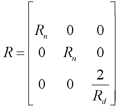

expressing the ideal state variable of the multi-port energy router system as:
wherein, udc expresses the DC side voltage of the multi-port energy router system, xref is ideal state variable, and Um is the largest output voltage of the generalized rectifier;
constructing an energy function of a state variable error xe = xref - x as:
therefore, rewriting the Eular-Largrange model of the generalized rectifier as:
to guarantee that errors of the multi-port energy router system consistently converge to 0 finally, introducing a damping injection factor as shown in the following formula:
wherein, Rp expresses the damping injection factor which is a symmetric positive definite damping matrix, namely
wherein, rp 1-r p3 all express virtual injection resistance;
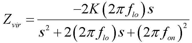
through regulating Rp , guaranteeing a Lyapunov direct stability criterion, obtaining a mutual-hierarchy stability recovery control strategy of the energy routers; and after the passive coupling impedance reshaping technology is adopted, executing step 5 again; and - step 7.3: for a phenomenon of group-hierarchy instability of the energy routers, realizing system stability through enlarging a power supply side output admittance matrix namely reducing the output impedance value in a Thevenin's equivalent circuit, and under the circumstance that a single energy router is stable, enabling the clustered energy router to only induce low frequency oscillation and synchronous instability but not whole frequency domain instability due to mutual coupling, so that designed virtual impedance adopts an impedance reshaping technology in a specific frequency domain, and the specific expression is shown as the following formula:

(fon - flo , fon + flo ) expresses an instability frequency range, K expresses an attenuation coefficient, Zvir expresses virtual impedance, flo expresses a lower frequency limit, fon expresses an upper frequency limit, and s expresses a Laplace multiplier; and
after the source side cascade impedance reshaping technology is adopted, executing thestep 6 again. - After adopting the technical solution, the self-mutual-group multilevel stability identification and stability recovery method for a multi-port energy router provided by the invention has the beneficial effects that the problem of complex stability evaluation of the clustered energy router is fundamentally solved, through a self-hierarchy stability identification technology, assumed conditions for the stability of each sub-module through a traditional impedance technology are eliminated, the coupling stability problem of multi-level power conversion devices is solved through a mutual-hierarchy stability identification technology, sufficient and necessary conditions for stability of a complex energy router network are obtained through a group-hierarchy stability identification technology finally, and the development of the Energy Internet is effectively promoted. For the stability problem of each hierarchy, a three-layer impedance reshaping stability recovery control strategy is proposed so as to guarantee the whole stability of the Energy Internet system and realize expandability, plug and play properties and safe and stable operation of the system.
-
-
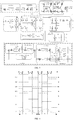
FIG. 1 shows the structural diagram of a single dual energy flow multi-port energy router system provided by the embodiment of the invention; -
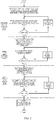
FIG. 2 shows the flow chart of a self-mutual-group multilevel stability identification and stability recovery method for a multi-port energy router provided by the embodiment of the invention; -
FIG. 3 shows the topology and control block diagram of the single dual energy flow multi-port energy router system provided by the embodiment of the invention; -
FIG. 4 shows the effect diagram of phase shifting control of a bidirectional bridge circuit in an energy router provided by the embodiment of the invention; -
FIG. 5 shows the schematic diagram of multiple nodes of the energy router provided by the embodiment of the invention; -
FIG. 6 shows the equivalent circuit diagram of multiple nodes of the energy router provided by the embodiment of the invention; -
FIG. 7 shows an equivalent diagram of a node k in the energy router provided by the embodiment of the invention; -
FIG. 8 shows the topology connection diagram of a clustered energy router provided by the embodiment of the invention; -
FIG. 9 shows the block diagram of passive coupling impedance reshaping control provided by the embodiment of the invention; and -
FIG. 10 shows the block diagram of source side cascade impedance reshaping control provided by the embodiment of the invention. - The detailed description in the invention will be further described in details with reference to appended drawings and embodiments. The following embodiments are used to illustrate the invention, but not to limit the scope of the invention.
- In the embodiment, a multi-port energy router system as shown in
FIG. 1 performs stability identification and stability recovery by a self-mutual-group multilevel stability identification and stability recovery method for a multi-port energy router disclosed by the invention. The multi-port energy router system comprises a voltage and current acquisition module, an impedance generation module, a communication module, an information processing module, a three-layer impedance reshaping module and the like, wherein the three-layer impedance reshaping module guarantees the whole stability of the system by adopting a three-layer impedance reshaping stability recovery control strategy. - The self-mutual-group multilevel stability identification and stability recovery method for a multi-port energy router, as shown in
FIG. 2 , comprises the following steps: - step 1: performing system parameter initialization on a single dual energy flow multi-port energy router system to be detected, wherein system parameters comprise a resistance value, an inductance value, a capacitance value, line impedance and switching frequency of three sub-systems of a front-end DC converter, a dual active bridge bidirectional DC-DC converter(Dual Active Bridge, namely DAB) and a back-end AC/DC converter in the energy router system, and parameters of energy storage equipment and photovoltaic equipment at multiple interfaces;
- step 2: constructing an Eular-Lagrange mathematical model according to a topology structure of the front-end DC converter, calculating a transfer function according to the mathematical model of the front-end DC converter, further judging the stability of the DC front end of the multi-port energy router system, if the judgment result shows instability, determining that the multi-port energy router system is in self-hierarchy instability, executing
step 7, or else, executingstep 3; - step 2.1: constructing a mathematical model according to a front-end DC circuit in the topology and control block diagram of a single dual energy flow multi-port energy router as shown in
FIG.3 , wherein CH is DC side output capacitance, Lr is AC side input filter inductance, Rr is AC side equivalent resistance, ug is grid voltage, ig is grid current, UH is DC side voltage, Db is a droop coefficient, Un is DC side rated voltage, Cv is introduced virtual capacitance, iREC is DC side current, iH is DC side output current, and H is a current feedforward coefficient; the mathematical expression of the front-end DC circuit is as shown in:
a PI controller is used as a current control inner loop which can be expressed as Gi (s) = krecpi + krecii / s;
and therefore, an equation (1) can be expressed as follows:
- step 2.2: according to the front-end DC circuit control strategy in the topology and control diagram of the single dual energy flow multi-port energy router as shown in
FIG. 3 , expressing a transfer function of the current inner loop as follows:
ignoring energy depletion, and simplifying the equation (3) as follows according to a principle of the same power on two sides of the front-end DC circuit:
further, expressing the transfer function of the equation (4) as follows:
according to a superposition principle, expressing the relationship of uH (s) and igd (s), as well as uH (s) and iH (s) as follows:
and ignoring the influence of grid voltage, applying a virtual inertia controller, a DC output current feedback controller and a voltage loop PI controller to the energy routers, and expressing a small-signal model as follows:
- wherein Gv (s)=krecpu + keciu / s,
- Gc (s)=Gi (s)/(Gi (s)+(Lrs+Rr )+H), and
- Gvir (s)=-1/(Db +Gv (s)Uns+H)
- step 2.3: performing processing through DSP according to the obtained transfer function of the front-end DC circuit to obtain data, transferring the data to a host computer through an SCI communication module, determining the number of right poles through calculating a Nyquist curve, if the number is zero, determining that the front-end DC circuit is stable, and executing
step 3, if the number is not zero, determining that the front-end DC circuit is not stable, and performingstep 7; - step 3: constructing an Eular-Lagrange mathematical model according to a topology structure of the dual active bridge bidirectional DC-DC converter, calculating a transfer function according to the mathematical model of the dual active bridge bidirectional DC-DC converter, further judging the stability, if the judgment result shows instability, determining that the multi-port energy router system is in self-hierarchy instability, executing the
step 7, or else, executingstep 4; - step 3.1: obtaining power conversion of a DAB structure through a power transmission control strategy of the dual active bridge bidirectional DC-DC converter, a DAB module and a power transmission control single phase shifting control strategy through
FIG. 3 , wherein a dual active bridge converter is used as a kernel module for voltage grade conversion and electrical isolation in the energy routers, the transformation ratio of a high-frequency transformer is n:1, CH ishigh-voltage side DC bus capacitance (the capacitance is the same as DC bus capacitance of the front-end DC circuit), CL is low-voltage side DC bus capacitance (the capacitance is the same as DC bus capacitance of a back-end AC-DC circuit), LT is the sum of leakage inductance and auxiliary induction of a high frequency transformer, UH is high-voltage side DC bus voltage, UL is low-voltage side DC bus voltage, U 12 and U 34 are high frequency chopping voltage output from an H bridge on two sides of the DAB, iT is original side current of the high frequency transformer, and iL is low-voltage DC side current of the DAB; - step 3.2: when the transformation ratio of the transformer is about 1, determining that a single phase shifting control strategy has smaller current stress compared with other phase shifting control strategies, wherein a control scheme is easier to realize,
FIG. 4 shows the schematic diagram of a driving signal and voltage and current of each switching tube of the DAB in single phase shifting control; obtaining the power transmission characteristics of the DAB under single phase shifting control through analysis of leakage inductance current of the transformer and voltage at two ends of the transformer at each time; and
obtaining high-voltage side power relationship of the DAB for deduction of DAB-grade power transmission characteristics:
- step 3.3: calculating a transfer function of voltage and current according to the obtained DAB power transfer relationship, judging stability, ordering Ds =d(1-d) in the above formula, and deducing output current of a DAB low-voltage side DC link as:

ordering

writing out a capacitance current equation in a DAB-grade low-voltage side DC link:
according to deduction of a DAB model equation, in order to be better adapted to practice, and considering a delay link Gd (s)=1/Tss+1 in control, wherein a PI link is Gdabpi (s)=kdabp +kdabi /s;
when load current changes, the regulation characteristics of DAB-grade low-voltage side DC voltage can be influenced, in order to reduce or eliminate the influence, introducing a feedforward control link into the load current in a controller,
writing the transfer function of the feedforward link in the following form:
wherein, F is a feedforward coefficient,
in order to eliminate the influence of the load current, obtaining:
therefore, determining the transfer function F of the feedforward link of the load current as:
taking the feedforward coefficient as F=1/kDAB, and deducing that a transfer function of DC bus voltage UL and a transfer function of disturbance quantity load current iLo before and after introducing feedforward can be respectively:
according to the obtained DAB transfer function, performing processing through the DSP to obtain data, transferring the data to the host computer through the SCI communication module, further determining the number of right poles through calculating the Nyquist curve, if the number is zero, determining that the DAB is stable, continuing to executestep 4, if the number is not zero, determining that the result is not stable, and performing thestep 7; - step 4: constructing an Eular-Lagrange mathematical model according to a circuit topology structure of the back-end AC/DC converter, calculating a transfer function according to the mathematical model of the back-end AC/DC converter, judging the stability of the back-end AC/DC converter according to a Nyquist curve of the transfer function, if the judgment result shows instability, determining that the multi-port energy router system is in self-hierarchy instability, executing the
step 7, or else, executing step 5; - step 4.1: constructing the mathematical model according to practical parameters of a back-end AC/DC circuit, wherein a part of topology structure of a back-end AC circuit is shown as
FIG. 3 , and a DC/AC conversion grade inductance current mathematical model under a rotating coordinate system can be expressed as:
according to the mathematical model, the electric quantity of dq shafts has coupling relationship, and in order to eliminate mutual influence on control and guarantee independent control of the dq shafts, a coupling quantity feedback value needs to be introduced into the controller so that the coupling relationship between the dq shafts can be eliminated; a regulator in the current inner loop adopts PI control to guarantee effective tracing of DC/AC conversion grade current; as shown in a control block diagram inFIG. 3 , the equation can be written as:
under a dq coordinate system, a system topology has inductance-current coupling relationship, so that a coupling quantity is introduced into a control layer to eliminate coupling variables; the model of a decoupled DC/AC conversion grade current inner loop controller can be expressed as:
considering the delay influence of a sampling link and a driving link on the controller, voltage loop decoupling control is further simplified as:
an open-loop transfer function of a dq shaft current inner loop is: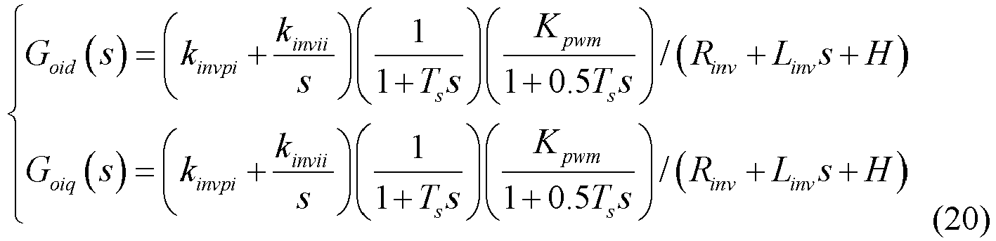
besides, a small-signal conversion function can be expressed as follows:
for a voltage outer loop as shown inFIG. 3 , according to similar analysis, the capacitance-voltage mathematical model of the DC/AC converter can be expressed as:
PI control is also applied to current control, and the formula is as follows:
considering sampling delay and symmetry of an external controller, a transfer function of the voltage outer loop can be expressed as:
- step 4.2: according to the transfer function of the obtained back-end AC/DC circuit, performing processing through a main control unit to obtain data, transferring the data to the host computer through the SCI communication module, further determining the number of right poles through calculating the Nyquist curve, if the number is zero, determining that the back-end AC/DC circuit is stable, and continuing to execute step 5, if the number is not zero, determining that the result is not stable, and performing the
step 7; - step 5: after determining that a basic three-level independent sub-system of the single dual energy flow multi-port energy router system is stable through steps 2-4, enabling new energy equipment including multi-load equipment, photovoltaic equipment and a fan to be accessed to front and back buses of the dual active bridge bidirectional DC-DC converter, and further determining the single stability of a single dual energy flow multi-port mutual-coupling energy router, wherein the front pole and the back pole of the dual active bridge bidirectional DC-DC converter are symmetrical, only the front-pole stability is explained in details as follows:
- step 5.1: enabling n pieces of different equipment including new energy equipment of load equipment, energy storage equipment, other photovoltaic equipment and the fan to be in parallel connection to a front grade of the dual active bridge bidirectional DC-DC converter, without considering the independent stability of the load device and the photovoltaic device, independently taking each interface in the multi-port energy router system as a sub-module due to existence of the line impedance and mutual coupling influence of input/output impedance after parallel connection of devices, wherein the line impedance exists between every two interfaces, enabling the structure of a multi-interface circuit to be equivalent to that of the Thevenin's circuit in image frequency coupling through a generalized bandwidth small-disturbance current injector, and judging system stability through constructing a system whole relationship function matrix extending to the periphery from interfaces, and closed-loop pole positions of the system;
- step 5.1.1: enabling n pieces of equipment to be in parallel connection to a bus at the front end of a DC converter and correspond to n nodes, setting each node to have a power supply and load, and enabling the line impedance to exist between a connection line of any two pieces of equipment, wherein the equipment having output external characteristic of outputting energy outwards is called as source equipment, and the equipment having the output external characteristic of consuming energy is called as load equipment;
the embodiment is simplistically analyzed by usingFIG. 5 as the structural diagram of a circuit of m interface equipment,FIG. 6 is the structure diagram of an interface of equipment k, the topology structure can be popularized to n equipment as shown inFIG. 7 , each node is set to have a power supply and load at the same time, for pure load, energy provided by the power supply is zero, for a power supply system, the load is zero, thus, switching between the source equipment and the load equipment at any time in an energy interaction process can be met, and a connection line between any two pieces of equipment has line impedance; - step 5.1.2: for analysis of the whole stability of the single dual energy flow multi-port energy router, because the stability of DC devices of external energy storage devices, new energy devices and the like can change along with changes of the number of interfaces, performing modeling on a multiple parallel connection system of the multi-port energy router by a matrix fractional criterion (MFC) method:
firstly, building a relationship function matrix of the whole multi-port energy router system, further obtaining the closed-loop pole positions of the system so as to judge the stability of the system, and building a relationship function matrix K(s) consisting of n*n relationship functions for the multi-port energy router system consisting of n pieces of equipment, wherein an element in the ath row and the bth line in the matrix is a relationship function constructed between equipment a and equipment b; - step 5.1.3: judging a zero point and a pole corresponding to each node in the K(s) by the MFC method, expressing the relationship function matrix as the ratio of two polynomial matrices, setting N(s)D -1(s) and A -1(s)B(s) as respectively to be any right MFC and any left MFC which cannot be simplified in the given relationship function matrix K(s), wherein N(s) expresses an any right MFC numerator part which cannot be simplified of the given relationship function matrix K(s), D(s) expresses an any right denominator part which cannot be simplified of the given relationship function matrix K(s), A(s) expresses an any right MFC denominator part which cannot be simplified of the given relationship function matrix K(s), and B(s) expresses an any right MFC numerator part which cannot be simplified of the given relationship function matrix K(s), and
expressing the zero point and the pole of the K(s) as: the pole of the K(s) is the root of det D(s)=0 or the root of det A(s)=0, and the zero point of the K(s) is an s value enabling the N(s) or the B(s) to be subjected to ranking reduction; and - step 5.1. 4:analyzing the equipment at any node k, wherein,Vk is voltage at the node k, iok is current output from a front-end DC circuit, ilinckj is current between the node k and a node j, Zloadk is local load impedance, iloadk is local load current, Zlinekj is line impedance between the node k and the node j, if the spacing between two nodes is small, the impedance can be ignored and is zero, then admittance is infinitely great,
then an equation describing the local load voltage and the local load current at the node k is:
an equation describing voltage and current between the node k and the node j is:
wherein Vj is voltage at the node j;
current output from the front-end DC circuit at the node k is:
wherein,
the expression of the local load current at the node k is:
wherein
the expression of current flowing from the node k to the node j is:
wherein
according to a kirchhoff's law, current flowing in the node k is equal to current flowing out of the node k, then
enabling the above-mentioned formula to be simultaneous, and obtaining equivalent impedance at the node k, as shown in the following formula:
wherein
extending the pole of the relationship function matrix K(s) to the whole energy routers and an external equipment system for analysis, and combining kirchhoff's formulas at all the nodes to form a matrix form:

enabling the two formulas to be simultaneous, and performing simplification:
wherein

with amatrix 

namely
- step 5.2: performing relative prime verification on the relationship matrix K(s) by a ranking criterion method, because p*p and p*q are n-order square matrices A(s) and B(s), the A(s) is a non-singular matrix namely a full rank matrix, and if rank[A(s)B(s)]=p, the A(s) and the B(s) are left relative primes; because


- step 6: after determining that the single dual energy flow multi-port energy router system is in single stability through the step 5, judging the stability of the whole clustered energy router system;
- step 6.1: when the system is obtained through mixed connection of m energy routers, obtaining the output impedance matrix of the clustered energy router system through the generalized bandwidth small-disturbance current injector, and performing denoising processing on the clustered energy router system through the following formula to obtain an admittance matrix flow diagram of the clustered energy router system,

wherein, TRi'j' and TGi'j' are mutual resistance and mutual conductance between the two energy routers, i'=1,···,m,j'=1,···,m,i'≠j', Gi'j' and Gj'i' are two groups of Thevenin's equivalent output admittance matrices obtained through analysis of the two energy routers from different angles, Zi'j' is an equivalent output impedance matrix from the ith energy router to the jth energy router, and
FIG. 8 can be obtained through two groups of the Thevenin's equivalent output admittance matrices; - step 6.2: according to a relevance and system stability characteristic condition of an admittance matrix, when steps 1-5 determine that the system is in self-hierarchy stability and mutual-hierarchy stability and the following formula does not have right poles:

determining that a clustered dual energy flow multi-port energy router system is stable, else, determining that the clustered dual energy flow multi-port energy router system is in group hierarchy instability of the energy routers, executing thestep 7, and performing three-layer impedance reshaping of a clustered energy router so that the system is stable; and - step 7: if a clustered single dual energy flow multi-port energy router system obtained through identification in the steps 2-6 has an instability result, respectively adopting a parameter self-regulation technology, a passive coupling impedance reshaping technology and a source side cascade impedance reshaping technology for instability links at different layers in the steps 2-6 so that the system is stable:
- step 7.1: for a phenomenon of self-hierarchy instability of the energy routers, according to a principle that the smaller a droop coefficient is, the higher the system stability is, regulating a droop control coefficient in the back-end DC converter of the single energy router through an arc tangent function, as shown in the following formula, and executing the
step 1 again;
wherein, R expresses the droop coefficient, R0 expresses an initial droop coefficient, k 1 and k 2 are proportional coefficients, and Γ is a shift coefficient; and the stability of the system can be improved through reducing the droop coefficient of a system sub-module, but along with reduction of the droop coefficient, the dynamic properties of the system can be partially lost, the coefficient can be slowly regulated through the characteristics of the arc tangent function, and after the parameter self-regulation technology is adopted, the system performs thestep 1; - step 7.2: for the phenomenon of mutual-hierarchy instability of the energy routers, enabling power supply side cascade impedance control to reduce impedance of a power supply side sub-system to meet stability of the system, enabling the front-end DC converter or the dual active bridge bidirectional DC-DC converter to be equivalent to be a generalized rectifier, wherein an Eular-Largrange model is expressed as:

wherein Ln ,Rn,Cd,Rd are respectively equivalent inductance and resistance of the front end of the generalized rectifier, and equivalent inductance and resistance of the back end of the generalized rectifier, udc ,id,iq are respectively DC front-end voltage and dq axial current of the generalized rectifier, ud,uq are respectively dq axial voltage of the output side of the rectifier, Sd and Sq respectively express switching duty cycles under a d-q coordinate system, and ω expresses angular velocity of the multi-port energy router system;
simplifying the above formula as:
wherein,

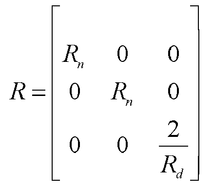

expressing the ideal state variable of the multi-port energy router system as:
wherein, udc expresses the DC side voltage of the multi-port energy router system, xref is ideal state variable, and Um is the largest output voltage of the generalized rectifier;
constructing an energy function of a state variable error xe = xref = x as:
therefore, rewriting the Eular-Largrange model of the generalized rectifier as:
to guarantee that errors of the multi-port energy router system consistently converge to 0 finally, introducing a damping injection factor as shown in the following formula:
wherein, Rp expresses the damping injection factor which is a symmetric positive definite damping matrix, namely
wherein, r p1-r p3 all express virtual injection resistance;
through regulating Rp , guaranteeing the Lyapunov direct stability criterion, obtaining a mutual-hierarchy stability recovery control strategy of an energy router, as shown inFIG. 9 ; and after the passive coupling impedance reshaping technology is adopted, executing step 5 again; and - step 7.3: for a phenomenon of group-hierarchy instability of the energy routers, realizing system stability through enlarging a power supply side output admittance matrix namely reducing the output impedance value in a Thevenin's equivalent circuit, and under the circumstance that a single energy router is stable, enabling the clustered energy router to only induce low frequency oscillation and synchronous instability but not whole frequency domain instability due to mutual coupling, so that designed virtual impedance adopts an impedance reshaping technology in a specific frequency domain, and the specific expression is shown as the following formula: as the energy router has a topology symmetric structure, an interconnection output source module can be compared with a generalized inverter, the control block diagram is shown as
FIG. 10 ,
(fon -flo,fon +flo ) expresses an instability frequency range, K expresses an attenuation coefficient, Zvir expresses virtual impedance, flo expresses a lower frequency limit, fon expresses an upper frequency limit, and s expresses a Laplace multiplier; and
after the source side cascade impedance reshaping technology is adopted, executing thestep 6 again.
- step 7.1: for a phenomenon of self-hierarchy instability of the energy routers, according to a principle that the smaller a droop coefficient is, the higher the system stability is, regulating a droop control coefficient in the back-end DC converter of the single energy router through an arc tangent function, as shown in the following formula, and executing the
- Finally, it should be noted that the above embodiments are merely intended to describe the technical solutions of the present invention, rather than to limit the present invention. Although the present invention is described in detail with reference to the above embodiments, persons of ordinary skill in the art should understand that they may still make modifications to the technical solutions described in the above embodiments or make equivalent replacements to some or all technical features thereof. However, these modifications or replacements do not cause the essence of the corresponding technical solutions to depart from the scope of the technical solutions of the embodiments of the present invention.
Claims (6)
- A self-mutual-group multilevel stability identification and stability recovery method for a multi-port energy router according to claim 1, characterized by comprising the following steps:step 1: performing system parameter initialization on a single dual energy flow multi-port energy router system to be detected, wherein system parameters comprise a resistance value, an inductance value, a capacitance value, line impedance and switching frequency of three sub-systems of a front-end DC converter, a dual active bridge bidirectional DC-DC converter and a back-end AC/DC converter in the energy router system, and parameters of energy storage equipment and photovoltaic equipment at multiple interfaces;step 2: constructing an Eular-Lagrange mathematical model according to a topology structure of the front-end DC converter, calculating a transfer function according to the mathematical model of the front-end DC converter, further judging the stability of the DC front end of the multi-port energy router system, if the judgment result shows instability, determining that the multi-port energy router system is in self-hierarchy instability, executing step 7, or else, executing step 3;step 3: constructing an Eular-Lagrange mathematical model according to a topology structure of the dual active bridge bidirectional DC-DC converter, calculating a transfer function according to the mathematical model of the dual active bridge bidirectional DC-DC converter, further judging the stability, if the judgment result shows instability, determining that the multi-port energy router system is in self-hierarchy instability, executing the step 7, or else, executing step 4;step 4: constructing an Eular-Lagrange mathematical model according to a circuit topology structure of the back-end AC/DC converter, calculating a transfer function according to the mathematical model of the back-end AC/DC converter, judging the stability of the back-end AC/DC converter according to a Nyquist curve of the transfer function, if the judgment result shows instability, determining that the multi-port energy router system is in self-hierarchy instability, executing the step 7, or else, executing step 5;step 5: after determining that a basic three-level independent sub-system of the single dual energy flow multi-port energy router system is stable through steps 2-4, enabling new energy equipment including multi-load equipment, photovoltaic equipment and a fan to be accessed to front and back buses of the dual active bridge bidirectional DC-DC converter, and further determining the single stability of a single dual energy flow multi-port mutual-coupling energy router; and if the judgment result shows instability, determining that the multi-port energy router system is in mutual-hierarchy instability, executing the step 7, or else, executing step 6;step 6: after determining that the single dual energy flow multi-port energy router system is in single stability through the step 5, judging the stability of the whole clustered energy router system, if the judgment result shows instability, determining that a clustered dual energy flow multi-port energy router system is in group hierarchy instability of the energy routers, executing the step 7, and performing three-layer impedance reshaping of a clustered energy router so that the system is stable; andstep 7: if a clustered single dual energy flow multi-port energy router system obtained through identification in the steps 2-6 has an instability result, respectively adopting a parameter self-regulation technology, a passive coupling impedance reshaping technology and a source side cascade impedance reshaping technology for instability links at different layers in the steps 2-6 so that the system is stable:step 7.1: for a phenomenon of self-hierarchy instability of the energy routers, according to a principle that the smaller a droop coefficient is, the higher the system stability is, regulating a droop control coefficient in the back-end DC converter of the single energy router through an arc tangent function, and executing the step 1 again;step 7.2: for a phenomenon of mutual-hierarchy instability of the energy routers, enabling power supply side cascade impedance control to reduce impedance of a power supply side sub-system to meet stability of the system, and after the passive coupling impedance reshaping technology is adopted, executing step 5 again; andstep 7.3: for a phenomenon of group-hierarchy instability of the energy routers, realizing system stability through enlarging a power supply side output admittance matrix namely reducing the output impedance value in a Thevenin's equivalent circuit, and under the circumstance that a single energy router is stable, enabling the clustered energy router to only induce low frequency oscillation and synchronous instability but not whole frequency domain instability due to mutual coupling, so that designed virtual impedance adopts an impedance reshaping technology in a specific frequency domain, and after the source side cascade impedance reshaping technology is adopted, executing the step 6 again.
- The self-mutual-group multilevel stability identification and stability recovery method for a multi-port energy router according to claim 1, characterized in that step 5.1 comprises specific steps:step 5.1: enabling n pieces of different equipment including new energy equipment of load equipment, energy storage equipment, other photovoltaic equipment and the fan to be in parallel connection to a front grade of the dual active bridge bidirectional DC-DC converter, without considering the independent stability of the load device and the photovoltaic device, independently taking each interface in the multi-port energy router system as a sub-module due to existence of the line impedance and mutual coupling influence of input/output impedance after parallel connection of devices, wherein the line impedance exists between every two interfaces, enabling the structure of a multi-interface circuit to be equivalent to that of the Thevenin's circuit in image frequency coupling through a generalized bandwidth small-disturbance current injector, and judging system stability through constructing a system whole relationship function matrix extending to the periphery from interfaces, and closed-loop pole positions of the system;step 5.1.1: enabling n pieces of equipment to be in parallel connection to a bus at the front end of a DC converter and correspond to n nodes, setting each node to have a power supply and load, and enabling the line impedance to exist between a connection line of any two pieces of equipment, wherein the equipment having output external characteristic of outputting energy outwards is called as source equipment, and the equipment having the output external characteristic of consuming energy is called as load equipment;step 5.1.2: performing modeling on a multiple parallel connection system of the multi-port energy router by a matrix fractional criterion (MFC) method:
firstly, building a relationship function matrix of the whole multi-port energy router system, further obtaining the closed-loop pole positions of the system so as to judge the stability of the system, and building a relationship function matrix K(s) consisting of n*n relationship functions for the multi-port energy router system consisting of n pieces of equipment, wherein an element in the ath row and the bth line in the matrix is a relationship function constructed between equipment a and equipment b;step 5.1.3: judging a zero point and a pole corresponding to each node in the K(s) by the MFC method, expressing the relationship function matrix as the ratio of two polynomial matrices, setting N(s)D -1(s) and A -1(s)B(s) as respectively to be any right MFC and any left MFC which cannot be simplified in the given relationship function matrix K(s), wherein N(s) expresses an any right MFC numerator part which cannot be simplified of the given relationship function matrix K(s), D(s) expresses an any right denominator part which cannot be simplified of the given relationship function matrix K(s), A(s) expresses an any right MFC denominator part which cannot be simplified of the given relationship function matrix K(s), and B(s) expresses an any right MFC numerator part which cannot be simplified of the given relationship function matrix K(s),and
expressing the zero point and the pole of the K(s) as: the pole of the K(s) is the root of det D(s)=0 or the root of det A(s)=0, and the zero point of the K(s) is an s value enabling the N(s) or the B(s) to be subjected to ranking reduction; andstep 5.1.4: analyzing the equipment at any node k, wherein k=1,...,n, Vk is voltage at the node k, iok is current output from a front-end DC circuit, ilinckj is current between the node k and a node j, j = 1, ..., n and j ≠ n, Zloadk is local load impedance, iloadk is local load current, Zlinekj is line impedance between the node k and the node j,
then an equation describing the local load voltage and the local load current at the node k is:

wherein, Vj is voltage at the node j;
current output from the front-end DC circuit at the node k is:

the expression of the local load current at the node k is: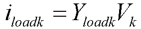
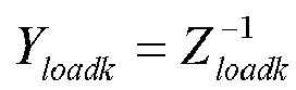


according to a kirchhoff's law, current flowing in the node k is equal to current flowing out of the node k, then

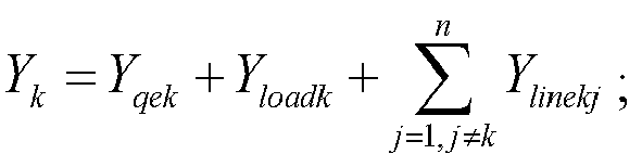


with a matrix

 step 5.2: performing relative prime verification on the relationship matrix K(s) by a ranking criterion method, because

- The self-mutual-group multilevel stability identification and stability recovery method for a multi-port energy router according to claim 2, characterized in that step 6 comprises specific steps:step 6.1: when the system is obtained through mixed connection of m energy routers, obtaining the output impedance matrix of the clustered energy router system through the generalized bandwidth small-disturbance current injector, and performing denoising processing on the clustered energy router system through the following formula to obtain an admittance matrix flow diagram of the clustered energy router system,

 step 6.2: according to a relevance and system stability characteristic condition of an admittance matrix, when steps 1-5 determine that the system is in self-hierarchy stability and mutual-hierarchy stability and the following formula does not have right poles:
- The self-mutual-group multilevel stability identification and stability recovery method for a multi-port energy router according to claim 3, characterized in that in step 7.1, a droop control coefficient in the back-end DC converter of the single energy router is regulated through an arc tangent function, as shown in the following formula:

- The self-mutual-group multilevel stability identification and stability recovery method for a multi-port energy router according to claim 4, characterized in that step 7.2 of enabling power supply side cascade impedance control to reduce impedance of a power supply side sub-system to meet stability of the system comprises specific substeps:enabling the front-end DC converter or the dual active bridge bidirectional DC-DC converter to be equivalent to be a generalized rectifier, wherein an Eular-Largrange model is expressed as:


 expressing the ideal state variable of the multi-port energy router system as:
 constructing an energy function of a state variable error xe = xref - x as:


 through regulating Rp , guaranteeing a Lyapunov direct stability criterion, and obtaining a mutual-hierarchy stability recovery control strategy of energy routers.
 - The self-mutual-group multilevel stability identification and stability recovery method for a multi-port energy router according to claim 5, characterized in that in step 7.3, the specific expression of the impedance reshaping technology in the specific frequency domain is shown as the following formula:
Applications Claiming Priority (2)
| Application Number | Priority Date | Filing Date | Title |
|---|---|---|---|
| CN201910674773.0A CN110401231B (en) | 2019-07-25 | 2019-07-25 | Multi-port energy router self-inter-group multi-level stability identification and stability return method |
| PCT/CN2019/098302 WO2021012298A1 (en) | 2019-07-25 | 2019-07-30 | Self-mutual-group multi-level stability identification and stability recovery method for multi-port energy router |
Publications (3)
| Publication Number | Publication Date |
|---|---|
| EP3817177A1 true EP3817177A1 (en) | 2021-05-05 |
| EP3817177A4 EP3817177A4 (en) | 2021-09-29 |
| EP3817177B1 EP3817177B1 (en) | 2024-03-13 |
Family
ID=68325086
Family Applications (1)
| Application Number | Title | Priority Date | Filing Date |
|---|---|---|---|
| EP19915586.2A Active EP3817177B1 (en) | 2019-07-25 | 2019-07-30 | Self-mutual-group multi-level stability identification and stability recovery method for multi-port energy router |
Country Status (3)
| Country | Link |
|---|---|
| EP (1) | EP3817177B1 (en) |
| CN (1) | CN110401231B (en) |
| WO (1) | WO2021012298A1 (en) |
Cited By (1)
| Publication number | Priority date | Publication date | Assignee | Title |
|---|---|---|---|---|
| CN117973090A (en) * | 2024-03-29 | 2024-05-03 | 锦浪科技股份有限公司 | A synchronous stability margin calculation method for heterogeneous multi-converter systems |
Families Citing this family (39)
| Publication number | Priority date | Publication date | Assignee | Title |
|---|---|---|---|---|
| CN111193286B (en) * | 2020-01-15 | 2023-04-07 | 云南电网有限责任公司电力科学研究院 | Coordination control method for combined converter in photovoltaic direct-current boosting and collecting system |
| CN112701886B (en) * | 2020-12-07 | 2022-03-25 | 齐鲁中科电工先进电磁驱动技术研究院 | Modular energy router, control method, device and medium |
| CN112994057B (en) * | 2021-02-05 | 2022-11-22 | 中国科学院电工研究所 | Economic operation control method of modular energy router system |
| CN113158422B (en) * | 2021-03-15 | 2024-07-09 | 国网陕西省电力公司电力科学研究院 | Synchronous condenser site selection method to improve the stability of large-scale new energy bases |
| CN113111623A (en) * | 2021-05-12 | 2021-07-13 | 南方电网科学研究院有限责任公司 | Design method and system of direct current loop impedance |
| CN113824163B (en) * | 2021-09-22 | 2024-06-18 | 深圳市信海致远科技有限公司 | Energy router and control method thereof |
| CN113964875B (en) * | 2021-11-29 | 2022-07-22 | 南通大学 | Stability analysis method for voltage source control type grid-connected converter |
| CN114492296B (en) * | 2022-01-25 | 2024-10-15 | 上海新相微电子股份有限公司 | Loop stability analysis method and device based on virtual-real mapping |
| CN114781428B (en) * | 2022-03-18 | 2024-03-26 | 华南理工大学 | small signal stability analysis method and system based on parallel grid-connected system of multiple virtual synchronous generators |
| CN114552660B (en) * | 2022-03-31 | 2025-09-23 | 东北大学 | Dual-use, full-operation-condition topology self-switching island-supported energy router |
| CN114865681B (en) * | 2022-04-25 | 2024-09-06 | 中国南方电网有限责任公司 | A method and device for determining oscillation |
| CN114784868B (en) * | 2022-05-11 | 2025-11-25 | 国网四川省电力公司攀枝花供电公司 | A Virtual Impedance Design Method for Grid-Connected Inverters Based on Parametric Stability Boundaries |
| CN115037120B (en) * | 2022-06-09 | 2024-04-30 | 合肥工业大学 | Two-stage energy router system and method based on modular multi-port converter |
| CN115051382B (en) * | 2022-06-22 | 2024-03-29 | 西南交通大学 | Method for establishing locomotive access three-phase power grid low-frequency oscillation modal analysis admittance model |
| CN115207957B (en) * | 2022-07-21 | 2024-07-05 | 东南大学 | A method for judging the stability of DC power distribution system based on bus port impedance |
| CN115249980B (en) * | 2022-08-18 | 2024-04-19 | 上海交通大学 | New energy station impedance identification method and system driven by combination of data and knowledge |
| CN115764856B (en) * | 2022-09-08 | 2025-07-22 | 东南大学 | Power spring cascading system stability analysis method based on component connection method |
| CN116090167B (en) * | 2022-11-28 | 2025-07-04 | 云南电网有限责任公司电力科学研究院 | A parameter estimation method and related equipment for LCL type grid-connected converter |
| CN115912310B (en) * | 2022-12-26 | 2025-10-14 | 浙江大学 | Impedance reshaping method for DC power supply system connected to water generation load |
| CN116207729A (en) * | 2022-12-29 | 2023-06-02 | 北京机电工程研究所 | Method for suppressing busbar oscillation of multi-voltage-class direct-current power distribution network and converter |
| CN116247638A (en) * | 2023-01-12 | 2023-06-09 | 西安西电电力电子有限公司 | Energy router power coordination control method and system including multi-energy storage converters |
| CN116305805B (en) * | 2023-01-31 | 2023-12-19 | 四川大学 | Model construction method for eliminating stability reduced-order analysis error of large-scale converter |
| CN116111804B (en) * | 2023-02-15 | 2025-10-14 | 厦门大学 | A control method for achieving cascade system stability |
| CN116345913B (en) * | 2023-02-28 | 2025-10-24 | 中南大学 | Stability Analysis Method of Digitally Controlled DC-DC Converters Based on Filippov Method |
| CN116362015B (en) * | 2023-03-06 | 2026-01-20 | 西北工业大学 | Modeling methods, systems, and terminals for power conversion systems in electric propulsion aircraft |
| CN116526550B (en) * | 2023-03-21 | 2026-04-17 | 锦浪科技股份有限公司 | Methods for constructing droop coefficient optimization models and methods for online adjustment of droop coefficients |
| CN116316535B (en) * | 2023-03-22 | 2023-09-12 | 广东工业大学 | Control method of direct-current bus voltage compensation device based on capacitive energy storage |
| CN118316045B (en) * | 2023-06-25 | 2026-03-10 | 广东电网有限责任公司珠海供电局 | Safety and stability assessment method suitable for alternating current-direct current series-parallel power system |
| CN116914829B (en) * | 2023-07-13 | 2025-01-28 | 三沙供电局有限责任公司 | A microgrid VSG control method based on fractional-order adaptation |
| CN116992776B (en) * | 2023-08-28 | 2024-03-26 | 山东大学 | Voltage source converter stability domain construction method and system based on piecewise affine |
| CN116842770B (en) * | 2023-09-01 | 2023-11-10 | 国网湖北省电力有限公司电力科学研究院 | Method, device and system for quantifying direct-current side dynamic interaction between grid-connected converters |
| CN116914801B (en) * | 2023-09-12 | 2023-11-14 | 四川大学 | Multiport energy router integrating power quality management function and control method thereof |
| CN117977983B (en) * | 2023-12-15 | 2024-12-03 | 中国人民解放军陆军工程大学 | Passive control method for injecting virtual energy storage |
| CN118300370B (en) * | 2024-03-14 | 2024-11-29 | 苏州湛泸科技有限公司 | A control method for an energy router capable of reducing energy transmission loss |
| CN118611136B (en) * | 2024-05-22 | 2026-03-24 | 中国电力科学研究院有限公司 | Methods and systems for determining the equivalent power station area of new energy power systems |
| CN119476162B (en) * | 2024-10-30 | 2025-11-28 | 重庆大学 | Network construction type direct-driven fan impedance modeling method considering frequency coupling effect |
| CN120180783B (en) * | 2025-05-23 | 2025-08-01 | 长沙理工大学 | A parameter design method and computer medium for a multi-machine grid-connected inverter interconnection system |
| CN120710021B (en) * | 2025-08-27 | 2025-11-04 | 昂顿科技(上海)有限公司 | A modular parallel control method and system for multi-port high-voltage SVG |
| CN121149961A (en) * | 2025-09-01 | 2025-12-16 | 华北电力大学 | Stability Analysis Method for Medium and Low Voltage DC Distribution Systems Including Line Networks |
Family Cites Families (6)
| Publication number | Priority date | Publication date | Assignee | Title |
|---|---|---|---|---|
| US8166447B1 (en) * | 2009-02-04 | 2012-04-24 | Altera Corporation | Power delivery network calculator tool for printed circuit board capacitors |
| CN104682430B (en) * | 2015-02-16 | 2016-08-17 | 东北大学 | A kind of energy router apparatus being applied to energy the Internet |
| CN106452136B (en) * | 2016-06-20 | 2019-04-02 | 清华大学 | A multi-port power electronic converter for energy internet |
| CN107017638A (en) * | 2017-05-23 | 2017-08-04 | 杭州电子科技大学 | A kind of many bus electric energy router topological structures of multiport suitable for power distribution network |
| CN109104105A (en) * | 2018-07-30 | 2018-12-28 | 东北电力大学 | One kind being directed to Three-phase PWM Voltage Rectifier and LLC resonant converter cascade system novel stable analysis method |
| CN109830995B (en) * | 2018-12-28 | 2021-03-02 | 浙江华云清洁能源有限公司 | An island control strategy based on energy router |
-
2019
- 2019-07-25 CN CN201910674773.0A patent/CN110401231B/en active Active
- 2019-07-30 WO PCT/CN2019/098302 patent/WO2021012298A1/en not_active Ceased
- 2019-07-30 EP EP19915586.2A patent/EP3817177B1/en active Active
Cited By (2)
| Publication number | Priority date | Publication date | Assignee | Title |
|---|---|---|---|---|
| CN117973090A (en) * | 2024-03-29 | 2024-05-03 | 锦浪科技股份有限公司 | A synchronous stability margin calculation method for heterogeneous multi-converter systems |
| CN117973090B (en) * | 2024-03-29 | 2024-06-07 | 锦浪科技股份有限公司 | Synchronous stability margin calculation method for heterogeneous multi-converter system |
Also Published As
| Publication number | Publication date |
|---|---|
| EP3817177A4 (en) | 2021-09-29 |
| EP3817177B1 (en) | 2024-03-13 |
| CN110401231A (en) | 2019-11-01 |
| WO2021012298A1 (en) | 2021-01-28 |
| CN110401231B (en) | 2023-01-03 |
Similar Documents
| Publication | Publication Date | Title |
|---|---|---|
| EP3817177B1 (en) | Self-mutual-group multi-level stability identification and stability recovery method for multi-port energy router | |
| CN107332261A (en) | A kind of micro-capacitance sensor quality of power supply distributed coordination administering method | |
| CN110808605B (en) | Dynamic stability analysis method for current mode droop control multi-terminal direct current system | |
| CN104022511B (en) | A kind of reduced dimension observer controlled for the damping of LCL parallel network reverse | |
| US20220366115A1 (en) | General decoupling method and system for electromagnetic transient simulation of voltage source converter | |
| CN107908829B (en) | Stability Analysis Method of Airborne Power System Based on Unified Large Signal Model | |
| CN103986187B (en) | Method for damping control of LCL grid-connected inverter based on dimension reduction observation | |
| CN117175696A (en) | Method for establishing transient synchronization model of grid-connected converter by considering current dynamics | |
| CN108418231A (en) | A kind of mixing multiport railway power inverter and its power coordination control method | |
| CN111654018B (en) | A DC bus voltage control method for a multi-port DC power distribution system | |
| CN112117784A (en) | Operation Control Method of Virtual Transformer | |
| CN114825369B (en) | Wind farm reduced-order method for grid-connected oscillation stability analysis of large-scale wind farms | |
| CN111525567A (en) | Method and device for calculating fault current of photovoltaic grid-connected inverter | |
| CN109830995B (en) | An island control strategy based on energy router | |
| CN111985066B (en) | Average dynamic phasor model suitable for multi-voltage-class direct-current power distribution system | |
| CN117154807A (en) | A method, system, equipment and medium for determining the stability of an AC/DC hybrid system | |
| CN104810854A (en) | Method for coordinating and controlling power between series-connected micro-grid and micro-sources of series-connected micro-grid | |
| Nguyen et al. | Power flow solution methods for combined transmission and distribution systems | |
| CN119382222A (en) | Sequence impedance modeling and stability analysis method for heterogeneous renewable energy grid-connected power systems | |
| CN118468600A (en) | A high-efficiency simulation method and system for electromagnetic transient of DFIG wind farm based on fine-grained network | |
| CN112307699B (en) | VSC-HVDC electromechanical transient simulation method and system based on phase components | |
| Kang et al. | Improved control of grid-connected photovoltaic and energy storage system based on virtual resistance | |
| Gao et al. | Sequence Admittance Model Decoupling Method for Grid-Connected Converters | |
| CN119202484B (en) | A performance analysis method for AC/DC hybrid power distribution system based on power balance | |
| CN119341521B (en) | Inverter sequence admittance simplified modeling method considering frequency coupling effect between alternating current and direct current and frequency coupling effect on alternating current side |
Legal Events
| Date | Code | Title | Description |
|---|---|---|---|
| STAA | Information on the status of an ep patent application or granted ep patent |
Free format text: STATUS: UNKNOWN |
|
| STAA | Information on the status of an ep patent application or granted ep patent |
Free format text: STATUS: THE INTERNATIONAL PUBLICATION HAS BEEN MADE |
|
| PUAI | Public reference made under article 153(3) epc to a published international application that has entered the european phase |
Free format text: ORIGINAL CODE: 0009012 |
|
| STAA | Information on the status of an ep patent application or granted ep patent |
Free format text: STATUS: REQUEST FOR EXAMINATION WAS MADE |
|
| PUAB | Information related to the publication of an a document modified or deleted |
Free format text: ORIGINAL CODE: 0009199EPPU |
|
| PUAI | Public reference made under article 153(3) epc to a published international application that has entered the european phase |
Free format text: ORIGINAL CODE: 0009012 |
|
| 17P | Request for examination filed |
Effective date: 20200828 |
|
| AK | Designated contracting states |
Kind code of ref document: A1 Designated state(s): AL AT BE BG CH CY CZ DE DK EE ES FI FR GB GR HR HU IE IS IT LI LT LU LV MC MK MT NL NO PL PT RO RS SE SI SK SM TR |
|
| A4 | Supplementary search report drawn up and despatched |
Effective date: 20210901 |
|
| RIC1 | Information provided on ipc code assigned before grant |
Ipc: H02J 3/38 20060101ALN20210826BHEP Ipc: H02J 3/02 20060101ALN20210826BHEP Ipc: H02M 3/335 20060101ALI20210826BHEP Ipc: H02M 1/00 20060101ALI20210826BHEP Ipc: H02J 1/10 20060101AFI20210826BHEP |
|
| DAV | Request for validation of the european patent (deleted) | ||
| DAX | Request for extension of the european patent (deleted) | ||
| REG | Reference to a national code |
Ref country code: DE Ref legal event code: R079 Ipc: H02J0001100000 Ref document number: 602019048437 Country of ref document: DE Free format text: PREVIOUS MAIN CLASS: H02J0003460000 |
|
| RIC1 | Information provided on ipc code assigned before grant |
Ipc: H02M 3/335 20060101ALN20230830BHEP Ipc: H02M 5/458 20060101ALN20230830BHEP Ipc: H02J 3/38 20060101ALN20230830BHEP Ipc: H02J 3/02 20060101ALN20230830BHEP Ipc: G06F 17/13 20060101ALI20230830BHEP Ipc: H02M 1/00 20060101ALI20230830BHEP Ipc: H02J 1/10 20060101AFI20230830BHEP |
|
| GRAP | Despatch of communication of intention to grant a patent |
Free format text: ORIGINAL CODE: EPIDOSNIGR1 |
|
| STAA | Information on the status of an ep patent application or granted ep patent |
Free format text: STATUS: GRANT OF PATENT IS INTENDED |
|
| INTG | Intention to grant announced |
Effective date: 20231012 |
|
| GRAS | Grant fee paid |
Free format text: ORIGINAL CODE: EPIDOSNIGR3 |
|
| GRAA | (expected) grant |
Free format text: ORIGINAL CODE: 0009210 |
|
| STAA | Information on the status of an ep patent application or granted ep patent |
Free format text: STATUS: THE PATENT HAS BEEN GRANTED |
|
| AK | Designated contracting states |
Kind code of ref document: B1 Designated state(s): AL AT BE BG CH CY CZ DE DK EE ES FI FR GB GR HR HU IE IS IT LI LT LU LV MC MK MT NL NO PL PT RO RS SE SI SK SM TR |
|
| REG | Reference to a national code |
Ref country code: GB Ref legal event code: FG4D |
|
| REG | Reference to a national code |
Ref country code: CH Ref legal event code: EP |
|
| REG | Reference to a national code |
Ref country code: DE Ref legal event code: R096 Ref document number: 602019048437 Country of ref document: DE |
|
| REG | Reference to a national code |
Ref country code: IE Ref legal event code: FG4D |
|
| P01 | Opt-out of the competence of the unified patent court (upc) registered |
Effective date: 20240307 |
|
| PG25 | Lapsed in a contracting state [announced via postgrant information from national office to epo] |
Ref country code: LT Free format text: LAPSE BECAUSE OF FAILURE TO SUBMIT A TRANSLATION OF THE DESCRIPTION OR TO PAY THE FEE WITHIN THE PRESCRIBED TIME-LIMIT Effective date: 20240313 |
|
| REG | Reference to a national code |
Ref country code: LT Ref legal event code: MG9D |
|
| PG25 | Lapsed in a contracting state [announced via postgrant information from national office to epo] |
Ref country code: GR Free format text: LAPSE BECAUSE OF FAILURE TO SUBMIT A TRANSLATION OF THE DESCRIPTION OR TO PAY THE FEE WITHIN THE PRESCRIBED TIME-LIMIT Effective date: 20240614 |
|
| REG | Reference to a national code |
Ref country code: NL Ref legal event code: MP Effective date: 20240313 |
|
| PG25 | Lapsed in a contracting state [announced via postgrant information from national office to epo] |
Ref country code: RS Free format text: LAPSE BECAUSE OF FAILURE TO SUBMIT A TRANSLATION OF THE DESCRIPTION OR TO PAY THE FEE WITHIN THE PRESCRIBED TIME-LIMIT Effective date: 20240613 Ref country code: HR Free format text: LAPSE BECAUSE OF FAILURE TO SUBMIT A TRANSLATION OF THE DESCRIPTION OR TO PAY THE FEE WITHIN THE PRESCRIBED TIME-LIMIT Effective date: 20240313 |
|
| PG25 | Lapsed in a contracting state [announced via postgrant information from national office to epo] |
Ref country code: ES Free format text: LAPSE BECAUSE OF FAILURE TO SUBMIT A TRANSLATION OF THE DESCRIPTION OR TO PAY THE FEE WITHIN THE PRESCRIBED TIME-LIMIT Effective date: 20240313 |
|
| PG25 | Lapsed in a contracting state [announced via postgrant information from national office to epo] |
Ref country code: RS Free format text: LAPSE BECAUSE OF FAILURE TO SUBMIT A TRANSLATION OF THE DESCRIPTION OR TO PAY THE FEE WITHIN THE PRESCRIBED TIME-LIMIT Effective date: 20240613 Ref country code: NO Free format text: LAPSE BECAUSE OF FAILURE TO SUBMIT A TRANSLATION OF THE DESCRIPTION OR TO PAY THE FEE WITHIN THE PRESCRIBED TIME-LIMIT Effective date: 20240613 Ref country code: LT Free format text: LAPSE BECAUSE OF FAILURE TO SUBMIT A TRANSLATION OF THE DESCRIPTION OR TO PAY THE FEE WITHIN THE PRESCRIBED TIME-LIMIT Effective date: 20240313 Ref country code: HR Free format text: LAPSE BECAUSE OF FAILURE TO SUBMIT A TRANSLATION OF THE DESCRIPTION OR TO PAY THE FEE WITHIN THE PRESCRIBED TIME-LIMIT Effective date: 20240313 Ref country code: GR Free format text: LAPSE BECAUSE OF FAILURE TO SUBMIT A TRANSLATION OF THE DESCRIPTION OR TO PAY THE FEE WITHIN THE PRESCRIBED TIME-LIMIT Effective date: 20240614 Ref country code: FI Free format text: LAPSE BECAUSE OF FAILURE TO SUBMIT A TRANSLATION OF THE DESCRIPTION OR TO PAY THE FEE WITHIN THE PRESCRIBED TIME-LIMIT Effective date: 20240313 Ref country code: ES Free format text: LAPSE BECAUSE OF FAILURE TO SUBMIT A TRANSLATION OF THE DESCRIPTION OR TO PAY THE FEE WITHIN THE PRESCRIBED TIME-LIMIT Effective date: 20240313 Ref country code: BG Free format text: LAPSE BECAUSE OF FAILURE TO SUBMIT A TRANSLATION OF THE DESCRIPTION OR TO PAY THE FEE WITHIN THE PRESCRIBED TIME-LIMIT Effective date: 20240313 |
|
| REG | Reference to a national code |
Ref country code: AT Ref legal event code: MK05 Ref document number: 1666671 Country of ref document: AT Kind code of ref document: T Effective date: 20240313 |
|
| PG25 | Lapsed in a contracting state [announced via postgrant information from national office to epo] |
Ref country code: SE Free format text: LAPSE BECAUSE OF FAILURE TO SUBMIT A TRANSLATION OF THE DESCRIPTION OR TO PAY THE FEE WITHIN THE PRESCRIBED TIME-LIMIT Effective date: 20240313 Ref country code: LV Free format text: LAPSE BECAUSE OF FAILURE TO SUBMIT A TRANSLATION OF THE DESCRIPTION OR TO PAY THE FEE WITHIN THE PRESCRIBED TIME-LIMIT Effective date: 20240313 |
|
| PG25 | Lapsed in a contracting state [announced via postgrant information from national office to epo] |
Ref country code: NL Free format text: LAPSE BECAUSE OF FAILURE TO SUBMIT A TRANSLATION OF THE DESCRIPTION OR TO PAY THE FEE WITHIN THE PRESCRIBED TIME-LIMIT Effective date: 20240313 |
|
| PG25 | Lapsed in a contracting state [announced via postgrant information from national office to epo] |
Ref country code: NL Free format text: LAPSE BECAUSE OF FAILURE TO SUBMIT A TRANSLATION OF THE DESCRIPTION OR TO PAY THE FEE WITHIN THE PRESCRIBED TIME-LIMIT Effective date: 20240313 |
|
| PG25 | Lapsed in a contracting state [announced via postgrant information from national office to epo] |
Ref country code: IS Free format text: LAPSE BECAUSE OF FAILURE TO SUBMIT A TRANSLATION OF THE DESCRIPTION OR TO PAY THE FEE WITHIN THE PRESCRIBED TIME-LIMIT Effective date: 20240713 |
|
| PG25 | Lapsed in a contracting state [announced via postgrant information from national office to epo] |
Ref country code: SM Free format text: LAPSE BECAUSE OF FAILURE TO SUBMIT A TRANSLATION OF THE DESCRIPTION OR TO PAY THE FEE WITHIN THE PRESCRIBED TIME-LIMIT Effective date: 20240313 Ref country code: PT Free format text: LAPSE BECAUSE OF FAILURE TO SUBMIT A TRANSLATION OF THE DESCRIPTION OR TO PAY THE FEE WITHIN THE PRESCRIBED TIME-LIMIT Effective date: 20240715 |
|
| PG25 | Lapsed in a contracting state [announced via postgrant information from national office to epo] |
Ref country code: EE Free format text: LAPSE BECAUSE OF FAILURE TO SUBMIT A TRANSLATION OF THE DESCRIPTION OR TO PAY THE FEE WITHIN THE PRESCRIBED TIME-LIMIT Effective date: 20240313 Ref country code: CZ Free format text: LAPSE BECAUSE OF FAILURE TO SUBMIT A TRANSLATION OF THE DESCRIPTION OR TO PAY THE FEE WITHIN THE PRESCRIBED TIME-LIMIT Effective date: 20240313 |
|
| PG25 | Lapsed in a contracting state [announced via postgrant information from national office to epo] |
Ref country code: AT Free format text: LAPSE BECAUSE OF FAILURE TO SUBMIT A TRANSLATION OF THE DESCRIPTION OR TO PAY THE FEE WITHIN THE PRESCRIBED TIME-LIMIT Effective date: 20240313 |
|
| PG25 | Lapsed in a contracting state [announced via postgrant information from national office to epo] |
Ref country code: PL Free format text: LAPSE BECAUSE OF FAILURE TO SUBMIT A TRANSLATION OF THE DESCRIPTION OR TO PAY THE FEE WITHIN THE PRESCRIBED TIME-LIMIT Effective date: 20240313 |
|
| PG25 | Lapsed in a contracting state [announced via postgrant information from national office to epo] |
Ref country code: SK Free format text: LAPSE BECAUSE OF FAILURE TO SUBMIT A TRANSLATION OF THE DESCRIPTION OR TO PAY THE FEE WITHIN THE PRESCRIBED TIME-LIMIT Effective date: 20240313 |
|
| PG25 | Lapsed in a contracting state [announced via postgrant information from national office to epo] |
Ref country code: SM Free format text: LAPSE BECAUSE OF FAILURE TO SUBMIT A TRANSLATION OF THE DESCRIPTION OR TO PAY THE FEE WITHIN THE PRESCRIBED TIME-LIMIT Effective date: 20240313 Ref country code: SK Free format text: LAPSE BECAUSE OF FAILURE TO SUBMIT A TRANSLATION OF THE DESCRIPTION OR TO PAY THE FEE WITHIN THE PRESCRIBED TIME-LIMIT Effective date: 20240313 Ref country code: RO Free format text: LAPSE BECAUSE OF FAILURE TO SUBMIT A TRANSLATION OF THE DESCRIPTION OR TO PAY THE FEE WITHIN THE PRESCRIBED TIME-LIMIT Effective date: 20240313 Ref country code: PT Free format text: LAPSE BECAUSE OF FAILURE TO SUBMIT A TRANSLATION OF THE DESCRIPTION OR TO PAY THE FEE WITHIN THE PRESCRIBED TIME-LIMIT Effective date: 20240715 Ref country code: PL Free format text: LAPSE BECAUSE OF FAILURE TO SUBMIT A TRANSLATION OF THE DESCRIPTION OR TO PAY THE FEE WITHIN THE PRESCRIBED TIME-LIMIT Effective date: 20240313 Ref country code: IS Free format text: LAPSE BECAUSE OF FAILURE TO SUBMIT A TRANSLATION OF THE DESCRIPTION OR TO PAY THE FEE WITHIN THE PRESCRIBED TIME-LIMIT Effective date: 20240713 Ref country code: EE Free format text: LAPSE BECAUSE OF FAILURE TO SUBMIT A TRANSLATION OF THE DESCRIPTION OR TO PAY THE FEE WITHIN THE PRESCRIBED TIME-LIMIT Effective date: 20240313 Ref country code: CZ Free format text: LAPSE BECAUSE OF FAILURE TO SUBMIT A TRANSLATION OF THE DESCRIPTION OR TO PAY THE FEE WITHIN THE PRESCRIBED TIME-LIMIT Effective date: 20240313 Ref country code: AT Free format text: LAPSE BECAUSE OF FAILURE TO SUBMIT A TRANSLATION OF THE DESCRIPTION OR TO PAY THE FEE WITHIN THE PRESCRIBED TIME-LIMIT Effective date: 20240313 |
|
| PG25 | Lapsed in a contracting state [announced via postgrant information from national office to epo] |
Ref country code: IT Free format text: LAPSE BECAUSE OF FAILURE TO SUBMIT A TRANSLATION OF THE DESCRIPTION OR TO PAY THE FEE WITHIN THE PRESCRIBED TIME-LIMIT Effective date: 20240313 |
|
| REG | Reference to a national code |
Ref country code: DE Ref legal event code: R097 Ref document number: 602019048437 Country of ref document: DE |
|
| PG25 | Lapsed in a contracting state [announced via postgrant information from national office to epo] |
Ref country code: IT Free format text: LAPSE BECAUSE OF FAILURE TO SUBMIT A TRANSLATION OF THE DESCRIPTION OR TO PAY THE FEE WITHIN THE PRESCRIBED TIME-LIMIT Effective date: 20240313 |
|
| PG25 | Lapsed in a contracting state [announced via postgrant information from national office to epo] |
Ref country code: DK Free format text: LAPSE BECAUSE OF FAILURE TO SUBMIT A TRANSLATION OF THE DESCRIPTION OR TO PAY THE FEE WITHIN THE PRESCRIBED TIME-LIMIT Effective date: 20240313 |
|
| PLBE | No opposition filed within time limit |
Free format text: ORIGINAL CODE: 0009261 |
|
| STAA | Information on the status of an ep patent application or granted ep patent |
Free format text: STATUS: NO OPPOSITION FILED WITHIN TIME LIMIT |
|
| PG25 | Lapsed in a contracting state [announced via postgrant information from national office to epo] |
Ref country code: DK Free format text: LAPSE BECAUSE OF FAILURE TO SUBMIT A TRANSLATION OF THE DESCRIPTION OR TO PAY THE FEE WITHIN THE PRESCRIBED TIME-LIMIT Effective date: 20240313 |
|
| REG | Reference to a national code |
Ref country code: DE Ref legal event code: R119 Ref document number: 602019048437 Country of ref document: DE |
|
| PG25 | Lapsed in a contracting state [announced via postgrant information from national office to epo] |
Ref country code: MC Free format text: LAPSE BECAUSE OF FAILURE TO SUBMIT A TRANSLATION OF THE DESCRIPTION OR TO PAY THE FEE WITHIN THE PRESCRIBED TIME-LIMIT Effective date: 20240313 |
|
| 26N | No opposition filed |
Effective date: 20241216 |
|
| REG | Reference to a national code |
Ref country code: CH Ref legal event code: PL |
|
| PG25 | Lapsed in a contracting state [announced via postgrant information from national office to epo] |
Ref country code: LU Free format text: LAPSE BECAUSE OF NON-PAYMENT OF DUE FEES Effective date: 20240730 |
|
| PG25 | Lapsed in a contracting state [announced via postgrant information from national office to epo] |
Ref country code: LU Free format text: LAPSE BECAUSE OF NON-PAYMENT OF DUE FEES Effective date: 20240730 |
|
| PG25 | Lapsed in a contracting state [announced via postgrant information from national office to epo] |
Ref country code: DE Free format text: LAPSE BECAUSE OF NON-PAYMENT OF DUE FEES Effective date: 20250201 |
|
| PG25 | Lapsed in a contracting state [announced via postgrant information from national office to epo] |
Ref country code: SI Free format text: LAPSE BECAUSE OF FAILURE TO SUBMIT A TRANSLATION OF THE DESCRIPTION OR TO PAY THE FEE WITHIN THE PRESCRIBED TIME-LIMIT Effective date: 20240313 Ref country code: BE Free format text: LAPSE BECAUSE OF NON-PAYMENT OF DUE FEES Effective date: 20240731 Ref country code: CH Free format text: LAPSE BECAUSE OF NON-PAYMENT OF DUE FEES Effective date: 20240731 |
|
| REG | Reference to a national code |
Ref country code: BE Ref legal event code: MM Effective date: 20240731 |
|
| PG25 | Lapsed in a contracting state [announced via postgrant information from national office to epo] |
Ref country code: IE Free format text: LAPSE BECAUSE OF NON-PAYMENT OF DUE FEES Effective date: 20240730 |
|
| PGFP | Annual fee paid to national office [announced via postgrant information from national office to epo] |
Ref country code: GB Payment date: 20250724 Year of fee payment: 7 |
|
| PGFP | Annual fee paid to national office [announced via postgrant information from national office to epo] |
Ref country code: FR Payment date: 20250728 Year of fee payment: 7 |
|
| PG25 | Lapsed in a contracting state [announced via postgrant information from national office to epo] |
Ref country code: CY Free format text: LAPSE BECAUSE OF FAILURE TO SUBMIT A TRANSLATION OF THE DESCRIPTION OR TO PAY THE FEE WITHIN THE PRESCRIBED TIME-LIMIT; INVALID AB INITIO Effective date: 20190730 |
|
| PG25 | Lapsed in a contracting state [announced via postgrant information from national office to epo] |
Ref country code: HU Free format text: LAPSE BECAUSE OF FAILURE TO SUBMIT A TRANSLATION OF THE DESCRIPTION OR TO PAY THE FEE WITHIN THE PRESCRIBED TIME-LIMIT; INVALID AB INITIO Effective date: 20190730 |