EP3817155A1 - Lever-type connector - Google Patents
Lever-type connector Download PDFInfo
- Publication number
- EP3817155A1 EP3817155A1 EP20203983.0A EP20203983A EP3817155A1 EP 3817155 A1 EP3817155 A1 EP 3817155A1 EP 20203983 A EP20203983 A EP 20203983A EP 3817155 A1 EP3817155 A1 EP 3817155A1
- Authority
- EP
- European Patent Office
- Prior art keywords
- housing
- lever
- cover
- lock arm
- mating
- Prior art date
- Legal status (The legal status is an assumption and is not a legal conclusion. Google has not performed a legal analysis and makes no representation as to the accuracy of the status listed.)
- Granted
Links
Images






Classifications
-
- H—ELECTRICITY
- H01—ELECTRIC ELEMENTS
- H01R—ELECTRICALLY-CONDUCTIVE CONNECTIONS; STRUCTURAL ASSOCIATIONS OF A PLURALITY OF MUTUALLY-INSULATED ELECTRICAL CONNECTING ELEMENTS; COUPLING DEVICES; CURRENT COLLECTORS
- H01R13/00—Details of coupling devices of the kinds covered by groups H01R12/70 or H01R24/00 - H01R33/00
- H01R13/46—Bases; Cases
- H01R13/52—Dustproof, splashproof, drip-proof, waterproof, or flameproof cases
- H01R13/5213—Covers
-
- H—ELECTRICITY
- H01—ELECTRIC ELEMENTS
- H01R—ELECTRICALLY-CONDUCTIVE CONNECTIONS; STRUCTURAL ASSOCIATIONS OF A PLURALITY OF MUTUALLY-INSULATED ELECTRICAL CONNECTING ELEMENTS; COUPLING DEVICES; CURRENT COLLECTORS
- H01R13/00—Details of coupling devices of the kinds covered by groups H01R12/70 or H01R24/00 - H01R33/00
- H01R13/62—Means for facilitating engagement or disengagement of coupling parts or for holding them in engagement
- H01R13/627—Snap or like fastening
- H01R13/6271—Latching means integral with the housing
- H01R13/6272—Latching means integral with the housing comprising a single latching arm
-
- H—ELECTRICITY
- H01—ELECTRIC ELEMENTS
- H01R—ELECTRICALLY-CONDUCTIVE CONNECTIONS; STRUCTURAL ASSOCIATIONS OF A PLURALITY OF MUTUALLY-INSULATED ELECTRICAL CONNECTING ELEMENTS; COUPLING DEVICES; CURRENT COLLECTORS
- H01R13/00—Details of coupling devices of the kinds covered by groups H01R12/70 or H01R24/00 - H01R33/00
- H01R13/62—Means for facilitating engagement or disengagement of coupling parts or for holding them in engagement
- H01R13/629—Additional means for facilitating engagement or disengagement of coupling parts, e.g. aligning or guiding means, levers, gas pressure electrical locking indicators, manufacturing tolerances
-
- H—ELECTRICITY
- H01—ELECTRIC ELEMENTS
- H01R—ELECTRICALLY-CONDUCTIVE CONNECTIONS; STRUCTURAL ASSOCIATIONS OF A PLURALITY OF MUTUALLY-INSULATED ELECTRICAL CONNECTING ELEMENTS; COUPLING DEVICES; CURRENT COLLECTORS
- H01R13/00—Details of coupling devices of the kinds covered by groups H01R12/70 or H01R24/00 - H01R33/00
- H01R13/62—Means for facilitating engagement or disengagement of coupling parts or for holding them in engagement
- H01R13/629—Additional means for facilitating engagement or disengagement of coupling parts, e.g. aligning or guiding means, levers, gas pressure electrical locking indicators, manufacturing tolerances
- H01R13/62933—Comprising exclusively pivoting lever
- H01R13/62955—Pivoting lever comprising supplementary/additional locking means
-
- H—ELECTRICITY
- H01—ELECTRIC ELEMENTS
- H01R—ELECTRICALLY-CONDUCTIVE CONNECTIONS; STRUCTURAL ASSOCIATIONS OF A PLURALITY OF MUTUALLY-INSULATED ELECTRICAL CONNECTING ELEMENTS; COUPLING DEVICES; CURRENT COLLECTORS
- H01R24/00—Two-part coupling devices, or either of their cooperating parts, characterised by their overall structure
-
- H—ELECTRICITY
- H01—ELECTRIC ELEMENTS
- H01R—ELECTRICALLY-CONDUCTIVE CONNECTIONS; STRUCTURAL ASSOCIATIONS OF A PLURALITY OF MUTUALLY-INSULATED ELECTRICAL CONNECTING ELEMENTS; COUPLING DEVICES; CURRENT COLLECTORS
- H01R13/00—Details of coupling devices of the kinds covered by groups H01R12/70 or H01R24/00 - H01R33/00
- H01R13/46—Bases; Cases
- H01R13/52—Dustproof, splashproof, drip-proof, waterproof, or flameproof cases
- H01R13/5202—Sealing means between parts of housing or between housing part and a wall, e.g. sealing rings
-
- H—ELECTRICITY
- H01—ELECTRIC ELEMENTS
- H01R—ELECTRICALLY-CONDUCTIVE CONNECTIONS; STRUCTURAL ASSOCIATIONS OF A PLURALITY OF MUTUALLY-INSULATED ELECTRICAL CONNECTING ELEMENTS; COUPLING DEVICES; CURRENT COLLECTORS
- H01R13/00—Details of coupling devices of the kinds covered by groups H01R12/70 or H01R24/00 - H01R33/00
- H01R13/46—Bases; Cases
- H01R13/52—Dustproof, splashproof, drip-proof, waterproof, or flameproof cases
- H01R13/5205—Sealing means between cable and housing, e.g. grommet
- H01R13/5208—Sealing means between cable and housing, e.g. grommet having at least two cable receiving openings
-
- H—ELECTRICITY
- H01—ELECTRIC ELEMENTS
- H01R—ELECTRICALLY-CONDUCTIVE CONNECTIONS; STRUCTURAL ASSOCIATIONS OF A PLURALITY OF MUTUALLY-INSULATED ELECTRICAL CONNECTING ELEMENTS; COUPLING DEVICES; CURRENT COLLECTORS
- H01R13/00—Details of coupling devices of the kinds covered by groups H01R12/70 or H01R24/00 - H01R33/00
- H01R13/62—Means for facilitating engagement or disengagement of coupling parts or for holding them in engagement
- H01R13/629—Additional means for facilitating engagement or disengagement of coupling parts, e.g. aligning or guiding means, levers, gas pressure electrical locking indicators, manufacturing tolerances
- H01R13/62933—Comprising exclusively pivoting lever
- H01R13/62938—Pivoting lever comprising own camming means
Definitions
- the present invention relates to a lever-type connector.
- a conventional lever-type connector includes a housing and a lever.
- the housing can be fitted with a mating housing.
- the lever is pivotably mounted to the housing, and is configured to fit the housing with the mating housing by pivoting.
- the housing is provided with a deflectable lock member.
- the lock member has as a base end, a root part that is integrally mounted to the housing, and functions as a lock arm that holds the lever at a pivoting completion position of the lever.
- Such a lever-type connector retains a fitting state of the housing and the mating housing by holding the lever at the pivoting completion position using the lock member.
- the present invention has been made in view of such a conventional problem, and it is an object of the present invention to provide a lever-type connector capable of stably retaining a fitting state of a housing and a mating housing.
- a lever-type connector including: a housing to be fitted with a mating housing; a lever pivotably mounted to the housing and fitting the housing with the mating housing by pivoting; and a cover mounted to the housing to cover an outer periphery of an electric cable drawn out from the housing, wherein the housing is provide with a deflectable lock arm, the lock arm having as a base end, a root part integrally mounted to the housing at a side where the housing faces the cover and holding the lever at a pivoting completion position of the lever, and the cover is provided with a protective wall arranged opposite to the root part of the lock arm.
- the cover is provided with an upper protective wall arranged opposite to the root part of the lock arm above the root part of the lock arm.
- an X-axis is defined as longitudinal directions of a mating housing 3, and a housing 5 and a cover 11 of a lever-type connector 1
- a Y-axis is defined as width directions of the mating housing 3, the housing 5 and the cover 11, and a Z-axis is defined as height directions of the mating housing 3, the housing 5 and the cover 11.
- the X-axis, the Y-axis and the Z-axis are perpendicular to one another.
- a side of the mating housing 3 in the housing 5 and a side of the housing 5 in the cover 11 are defined as +X side
- a side of the cover 11 in the housing 5 is defined as -X side.
- the lever-type connector 1 includes the housing 5 and the lever 7.
- the housing 5 can be fitted with the mating housing 3.
- the lever 7 is pivotably mounted to the housing 5, and is configured to fit the housing 5 with the mating housing 3 by pivoting.
- the lever-type connector 1 also includes the cover 11 mounted to the housing 5.
- the cover 11 is configured to cover an outer periphery of an electric cable 9 drawn out from the housing 5.
- the housing 5 is provided with a deflectable lock arm 15.
- the lock arm 15 has as a base end, a root part 13 that is integrally mounted to the housing 5 at a side (-X side) where the housing 5 faces the cover 11, and holds the lever 7 at a pivoting completion position of the lever 7.
- the cover 11 is provided with a protective wall 17.
- the protective wall 17 is arranged opposite to the root part 13 of the lock arm 15. More specifically, the protective wall 17 is arranged opposite to a side surface of the root part 13.
- the housing 5 includes an inner housing 19 and an outer housing 21.
- the inner housing 19 is made of an insulating material such as a synthetic resin.
- the inner housing 19 is formed into a casing-like shape such that the inner housing 19 can be fitted to the mating housing 3.
- the inner housing 19 includes a plurality of terminal receiving chambers 23.
- Each of the terminal receiving chambers 23 is extended in the inner housing 19, in a direction (X-axis direction) where the housing 5 is fitted with the mating housing 3.
- the terminal receiving chambers 23 are arranged in a line in a width direction (Y-axis direction) of the inner housing 19 and in a line a height direction (Z-axis direction) of the inner housing 19.
- a locking lance 25 is deflectably mounted in each of the terminal receiving chambers 23, a locking lance 25 is deflectably mounted.
- the locking lance 25 is locked to a terminal 29 received in the corresponding terminal receiving chamber 23 to prevent the terminal 29 from coming off from the corresponding terminal receiving chamber 23.
- a regulating member 27 is inserted into a space within the corresponding terminal receiving chamber 23 formed in a deflection direction of the locking lance 25. In a state where the locking lance 25 is locked to the terminal 29, the regulating member 27 regulates a deflection of the locking lance 25.
- the terminal 29 is a female-type terminal having a connection part formed into a box-like shape.
- the terminal 29 is electrically connected to a terminal part of an electric cable 9.
- the electric cable 9 is electrically connected to a power source, a device or the like.
- the terminal 29 is introduced in the corresponding terminal receiving chamber 23 through an opening of the corresponding terminal receiving chamber 23, and then received in the corresponding terminal receiving chamber 23.
- the opening is formed at a side (-X side) opposite to a fitting surface of the inner housing 19 where the inner housing 19 is fitted to the mating housing 3.
- the electric cable 9 is drawn out to the outside of the housing 5 through the opening of the corresponding terminal receiving chamber 23
- the electric cable 9 is provided with a rubber stopper 31.
- the rubber stopper 31 adheres to an outer periphery of the electric cable 9 and an inner periphery of the corresponding terminal receiving chamber 23, between the electric cable 9 and the corresponding terminal receiving chamber 23 to prevent water from entering the inner housing 19.
- the outer housing 21 is made of an insulating material such as a synthetic resin.
- the outer housing 21 can accommodate the inner housing 19.
- the outer housing 21 is formed into a casing-like shape such that the mating housing 3 can be inserted in the outer housing 21.
- the outer housing 21 accommodates the inner housing 19 and holds the inner housing 19 by using a locking part 33 deflectably mounted to the outer housing 21.
- a spring S intervenes between the outer housing 21 and the inner housing 19 and allows the outer housing 21 and the inner housing 19 to relatively slide.
- a packing 35 is arranged between the outer housing 21 and the inner housing 19.
- the packing 35 prevents water from entering between the outer housing 21 and the inner housing 19. In a state where the outer housing 21 accommodates the inner housing 19, the mating housing 3 is inserted in the outer housing 21 to be fitted to the inner housing 19.
- the mating housing 3 is made of an insulating material such as a synthetic resin.
- the mating housing 3 is formed into a casing-like shape such that the mating housing 3 can be inserted in the outer housing 21 and the inner housing 19 can be fitted to the mating housing 3 within the mating housing 3.
- a plurality of mating terminals 37 is received.
- Each of the mating terminals 37 is a male-type terminal having a connection part formed into a tab shape by an insert molding, a press fitting or the like.
- the mating housing 3 is fitted with the inner housing 19 such that each of the mating terminals 37 is electrically connected to the corresponding terminal 29 in the corresponding terminal receiving chamber 23.
- Such a fitting of the mating housing 3 and the housing 5 is performed by pivoting of the lever 7 pivotably mounted to the housing 5.
- the lever 7 is mainly made of a metal material.
- parts made of an insulating material such as a synthetic resin are mounted to a part of each of sidewalls 39, 39 and a part of a linking part 41 of the lever 7.
- the lever 7 may be made of only an insulating material such as a synthetic resin.
- the lever 7 includes a pair of the sidewalls 39, 39 and the linking part 41 linking the sidewalls 39, 39 to each other.
- the lever 7 is formed to have a width larger than that of the housing 5 by the sidewalls 39, 39 and the linking part 41.
- the lever 7 is provided with shaft holes 43, 43 and cam grooves 45, 45.
- the shaft holes 43, 43 penetrate the sidewalls 39, 39 of the lever 7 respectively.
- Shaft parts 47, 47 projected from both side surfaces of the outer housing 21, are engaged to the shaft holes 43, 43.
- the lever 7 is pivotably mounted to the outer periphery of the housing 5.
- the cam grooves 45, 45 penetrate the sidewalls 39, 39 of the lever 7 respectively.
- Each of the cam grooves 45, 45 opens at a side of a fitting surface (+X side) of the housing 5 where the housing 5 is fitted with the mating housing 3.
- cam pins 49, 49 projected from both side surfaces of the mating housing 3 are respectively inserted in the cam grooves 45, 45 from the openings of the cam grooves 45, 45, by pivoting of the lever 7.
- the lever 7 can pivot between the pivoting initial position (see FIG. 3 ) and the pivoting completion position (see FIG. 5 ).
- the cam pins 49, 49 of the mating housing 3 are respectively inserted in the cam grooves 45, 45 of the lever 7.
- the lock arm 15 is deflectably mounted to the housing 5.
- the lock arm 15 has as the base end, the root part 13 that is formed by a single member continuously connected to the housing 5, at a side (-X side) where the cover 11 is mounted to the housing 5, on an upper surface of the housing 5.
- An engaging part 51 is formed in a stepped shape near the center of the lock arm 15.
- the engaging part 51 is engaged with an engaged part 53 mounted to the linking part 41 of the lever 7 at the pivoting completion position of the lever 7. By the engagement of the engaging part 51 and the engaged part 53, the lever 7 is held at the pivoting completion position of the lever 7 to retain the fitting state of the mating housing 3 and the housing 5.
- a recessed part 52 is formed at a side of the root part 13 (-X side) in the lock arm 15 (see FIG. 1 ).
- the recessed part 52 has an opened upper surface and an opened rear surface.
- An upper surface of the root part 13 is continuously connected to a bottom surface of the recessed part 52.
- a release operation part 55 is mounted to the lock arm 15 at a side of a free end (+X side) of the lock arm 15.
- the release operation part 55 deflects the lock arm 15 downward.
- the engagement of the engaging part 51 and the engaged part 53 is released (see FIG. 6 ).
- the lever can pivot from the pivoting completion position toward the pivoting initial position.
- the cover 11 is mounted to the housing 5 at a side of the root part 13 (-X side) of the lock arm 15.
- the cover 11 is made of an insulating material such as a synthetic resin, and includes an upper cover part 57 and a lower cover part 59.
- the upper cover part 57 is provided with engaging parts 61, 61 on both sidewalls of the upper cover part 57.
- the upper cover part 57 and the lower cover part 59 are respectively provided with electric cable leading parts 63, 63 each of which is formed into a semicircular shape.
- the upper cover part 57 and the lower cover part 59 are respectively provided with engaging parts 65, 67.
- the cover 11 is mounted to the housing 5 in a unified manner. Since the cover 11 configured to cover the electric cable 9 drawn out from the housing 5, is divided the upper cover part 57 and the lower cover part 59, the cover 11 is easily mounted to the housing 5.
- the upper cover part 57 of the cover 11 is provided with a protective wall 17 at a side of the lock arm 15 (+X side) in the cover 11.
- the protective wall 17 is formed by a single member continuously connected to the upper cover part 57 and stands upward on an upper surface of the upper cover part 57. In a state where the cover 11 is mounted to the housing 5, the protective wall 17 is arranged opposite to the root part 13 of the lock arm 15. By arranging the protective wall 17 such that the protective wall 17 faces the root part 13 of the lock arm 15, the electric cable 9 drawn out from the housing 5, a peripheral member or the like can be prevented from interfering with the root part 13.
- the lock arm 15 can stably hold the lever 7 at the pivoting completion position, which stably retains a fitting state of the mating housing 3 and the housing 5.
- the lever-type connector 1 can stably hold the lever 7 at the pivoting completion position using the lock arm 15, which stably retains a fitting state of the mating housing 3 and the housing 5.
- an X-axis is defined as the longitudinal directions of the mating housing 3, and the housing 5 and the cover 11 of a lever-type connector 101
- a Y-axis is defined as the width directions of the mating housing 3, the housing 5 and the cover 11
- the Z-axis is defined as the height directions of the mating housing 3, the housing 5 and the cover 11.
- the X-axis, the Y-axis and the Z-axis are perpendicular to one another.
- a side of the mating housing 3 in the housing 5 and a side of the housing 5 in the cover 11 are defined as +X side
- a side of the cover 11 in the housing 5 is defined as -X side.
- the cover 11 is provided with an upper protective wall 103 arranged opposite to the root part 13 of the lock arm 15 above the root part 13 of the lock arm 15. More specifically, the upper protective wall 103 is arranged opposite to the upper surface of the root part 13.
- the upper cover part 57 of the cover 11 is provided with the upper protective wall 103.
- the upper protective wall 103 is formed by a single member continuously connected to the protective wall 17.
- the upper protective wall 103 extends toward a side of the housing 5 (+X side) from an upper end of the protective wall 17. In a state where the cover 11 is mounted to the housing 5, the upper protective wall 103 is arranged opposite to the root part 13 of the lock arm 15 above the root part 13 of the lock arm 15.
- the upper protective wall 103 By arranging the upper protective wall 103 such that the upper protective wall 103 faces the root part 13 of the lock arm 15 above the root part 13 of the lock arm 15, it is possible to protect the root part 13 of the lock arm 15 using the protective wall 17 and the upper protective wall 103. Due to this, the electric cable 9 drawn out from the housing 5, a peripheral member or the like can be further prevented from interfering with the root part 13.
- the cover 11 is provided with the upper protective wall 103 arranged opposite to the root part 13 of the lock arm 15 above the root part 13 of the lock arm 15, it is possible to prevent an external force from being applied to the root part 13 using the protective wall 17 and the upper protective wall 103. This further prevents the occurrence of damage in the root part 13 of the lock arm 15.
- the upper protective wall 103 is integrally mounted to the protective wall 17 and extends from an upper end of the protective wall 17 in the second embodiment, the invention is not limited to this.
- the upper protective wall 103 may be extend from another part of the protective wall 17.
- the upper protective wall 103 is formed by a single member continuously connected to the protective wall 17, the invention is not limited this.
- the upper protective wall 103 may be formed by a member independent of the protective wall 17.
- the upper protective wall 103 may extend from a different position from the position where the protective wall 17 is provided, in the cover 11.
Landscapes
- Details Of Connecting Devices For Male And Female Coupling (AREA)
Abstract
Description
- The present invention relates to a lever-type connector.
- A conventional lever-type connector includes a housing and a lever. The housing can be fitted with a mating housing. The lever is pivotably mounted to the housing, and is configured to fit the housing with the mating housing by pivoting. There is also a lever-type connector with a cover mounted to the housing. The cover is configured to cover an outer periphery of an electric cable drawn out from the housing (see
JP 2018-41627 - In the lever-type connector, the housing is provided with a deflectable lock member. The lock member has as a base end, a root part that is integrally mounted to the housing, and functions as a lock arm that holds the lever at a pivoting completion position of the lever.
- Such a lever-type connector retains a fitting state of the housing and the mating housing by holding the lever at the pivoting completion position using the lock member.
- In the lever-type connector as described in
JP 2018-41627 - However, the root part of the lock arm is exposed to the outside at the pivoting completion position of the lever. Due to this, there is a possibility that an external force such as an interference with a peripheral member will be applied to the root part of the lock arm at the pivoting completion position.
- It is concerned that a damage such as a plastic deformation or a fracture occurs in the root part of the lock arm when the external force is applied to the root part. If the damage occurs in the root part, the lock arm cannot hold the lever at the pivoting completion position. In this case, there is a possibility that the lever-type connector cannot retain the fitting state of the housing and the mating housing
- The present invention has been made in view of such a conventional problem, and it is an object of the present invention to provide a lever-type connector capable of stably retaining a fitting state of a housing and a mating housing.
- According to the invention, there is provided a lever-type connector including: a housing to be fitted with a mating housing; a lever pivotably mounted to the housing and fitting the housing with the mating housing by pivoting; and a cover mounted to the housing to cover an outer periphery of an electric cable drawn out from the housing, wherein the housing is provide with a deflectable lock arm, the lock arm having as a base end, a root part integrally mounted to the housing at a side where the housing faces the cover and holding the lever at a pivoting completion position of the lever, and the cover is provided with a protective wall arranged opposite to the root part of the lock arm.
- It is preferred that the cover is provided with an upper protective wall arranged opposite to the root part of the lock arm above the root part of the lock arm.
- According to the invention, it is possible to provide a lever-type connector capable of stably retaining a fitting state of a housing and a mating housing.
-
-
FIG. 1 is a disassembled perspective view of a lever-type connector according to a first embodiment of the present invention. -
FIG. 2 is a side view illustrating a state before the lever-type connector according to the first embodiment is fitted with a mating housing. -
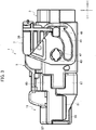
FIG. 3 is a side view illustrating a state where a lever of the lever-type connector according to the first embodiment is located at a pivoting initial position. -
FIG. 4 is a side view illustrating a state where the lever of the lever-type connector according to the first embodiment pivots from the pivoting initial position. -
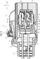
FIG. 5 is a cross-sectional view illustrating a state where the lever-type connector according to the first embodiment is fitted with the mating housing. -
FIG. 6 is a cross-sectional view illustrating a state where holding of the lever by a lock arm of the lever-type connector according to the first embodiment is released. -
FIG. 7 is a cross-sectional view illustrating a state where a lever-type connector according to a second embodiment is fitted with the mating housing. -
FIG. 8 is a perspective view of a cover of the lever-type connector according to the second embodiment. - A lever-type connector according to exemplary embodiments will be described in detail below with reference to drawings. Note that since a dimensional ratio of each element is exaggerated in the drawings for convenience of explanation, there is a case where the dimensional ratio in the drawings differs from an actual dimensional ratio.
- A first embodiment will be described with reference to
FIG. 1 to FIG. 6 . Note that inFIG. 1 to FIG. 6 , an X-axis is defined as longitudinal directions of amating housing 3, and ahousing 5 and acover 11 of a lever-type connector 1, a Y-axis is defined as width directions of themating housing 3, thehousing 5 and thecover 11, and a Z-axis is defined as height directions of themating housing 3, thehousing 5 and thecover 11. The X-axis, the Y-axis and the Z-axis are perpendicular to one another. In the lever-type connector 1, a side of themating housing 3 in thehousing 5 and a side of thehousing 5 in thecover 11 are defined as +X side, and a side of thecover 11 in thehousing 5 is defined as -X side. - The lever-
type connector 1 according to the present embodiment includes thehousing 5 and thelever 7. Thehousing 5 can be fitted with themating housing 3. Thelever 7 is pivotably mounted to thehousing 5, and is configured to fit thehousing 5 with themating housing 3 by pivoting. The lever-type connector 1 also includes thecover 11 mounted to thehousing 5. Thecover 11 is configured to cover an outer periphery of anelectric cable 9 drawn out from thehousing 5. - The
housing 5 is provided with adeflectable lock arm 15. Thelock arm 15 has as a base end, aroot part 13 that is integrally mounted to thehousing 5 at a side (-X side) where thehousing 5 faces thecover 11, and holds thelever 7 at a pivoting completion position of thelever 7. - The
cover 11 is provided with aprotective wall 17. Theprotective wall 17 is arranged opposite to theroot part 13 of thelock arm 15. More specifically, theprotective wall 17 is arranged opposite to a side surface of theroot part 13. - As illustrated in
FIG. 1 to FIG. 6 , thehousing 5 includes aninner housing 19 and anouter housing 21. Theinner housing 19 is made of an insulating material such as a synthetic resin. Theinner housing 19 is formed into a casing-like shape such that theinner housing 19 can be fitted to themating housing 3. Theinner housing 19 includes a plurality of terminal receivingchambers 23. - Each of the
terminal receiving chambers 23 is extended in theinner housing 19, in a direction (X-axis direction) where thehousing 5 is fitted with themating housing 3. Theterminal receiving chambers 23 are arranged in a line in a width direction (Y-axis direction) of theinner housing 19 and in a line a height direction (Z-axis direction) of theinner housing 19. In each of theterminal receiving chambers 23, a lockinglance 25 is deflectably mounted. - The locking
lance 25 is locked to a terminal 29 received in the correspondingterminal receiving chamber 23 to prevent the terminal 29 from coming off from the correspondingterminal receiving chamber 23. A regulatingmember 27 is inserted into a space within the correspondingterminal receiving chamber 23 formed in a deflection direction of the lockinglance 25. In a state where the lockinglance 25 is locked to the terminal 29, the regulatingmember 27 regulates a deflection of the lockinglance 25. - As illustrated in
FIG. 5 andFIG. 6 , the terminal 29 is a female-type terminal having a connection part formed into a box-like shape. The terminal 29 is electrically connected to a terminal part of anelectric cable 9. Theelectric cable 9 is electrically connected to a power source, a device or the like. In a state where the terminal 29 is electrically connected to the terminal part of theelectric cable 9, the terminal 29 is introduced in the correspondingterminal receiving chamber 23 through an opening of the correspondingterminal receiving chamber 23, and then received in the correspondingterminal receiving chamber 23. In the correspondingterminal receiving chamber 23, the opening is formed at a side (-X side) opposite to a fitting surface of theinner housing 19 where theinner housing 19 is fitted to themating housing 3. - In a state where the
terminal 29 is received in the correspondingterminal receiving chamber 23, theelectric cable 9 is drawn out to the outside of thehousing 5 through the opening of the correspondingterminal receiving chamber 23 Theelectric cable 9 is provided with arubber stopper 31. Therubber stopper 31 adheres to an outer periphery of theelectric cable 9 and an inner periphery of the correspondingterminal receiving chamber 23, between theelectric cable 9 and the correspondingterminal receiving chamber 23 to prevent water from entering theinner housing 19. - As illustrated in
FIG. 1 to FIG. 6 , theouter housing 21 is made of an insulating material such as a synthetic resin. Theouter housing 21 can accommodate theinner housing 19. Theouter housing 21 is formed into a casing-like shape such that themating housing 3 can be inserted in theouter housing 21. Theouter housing 21 accommodates theinner housing 19 and holds theinner housing 19 by using a lockingpart 33 deflectably mounted to theouter housing 21. A spring S intervenes between theouter housing 21 and theinner housing 19 and allows theouter housing 21 and theinner housing 19 to relatively slide. - A packing 35 is arranged between the
outer housing 21 and theinner housing 19. The packing 35 prevents water from entering between theouter housing 21 and theinner housing 19. In a state where theouter housing 21 accommodates theinner housing 19, themating housing 3 is inserted in theouter housing 21 to be fitted to theinner housing 19. - As illustrated in
FIG. 1 to FIG. 6 , themating housing 3 is made of an insulating material such as a synthetic resin. Themating housing 3 is formed into a casing-like shape such that themating housing 3 can be inserted in theouter housing 21 and theinner housing 19 can be fitted to themating housing 3 within themating housing 3. In themating housing 3, a plurality ofmating terminals 37 is received. Each of themating terminals 37 is a male-type terminal having a connection part formed into a tab shape by an insert molding, a press fitting or the like. - The
mating housing 3 is fitted with theinner housing 19 such that each of themating terminals 37 is electrically connected to the correspondingterminal 29 in the correspondingterminal receiving chamber 23. Such a fitting of themating housing 3 and thehousing 5 is performed by pivoting of thelever 7 pivotably mounted to thehousing 5. - As illustrated in
FIG. 1 to FIG. 6 , thelever 7 is mainly made of a metal material. For example, parts made of an insulating material such as a synthetic resin, are mounted to a part of each ofsidewalls part 41 of thelever 7. Note that thelever 7 may be made of only an insulating material such as a synthetic resin. Thelever 7 includes a pair of thesidewalls part 41 linking thesidewalls lever 7 is formed to have a width larger than that of thehousing 5 by thesidewalls part 41. Thelever 7 is provided with shaft holes 43, 43 andcam grooves - The shaft holes 43, 43 penetrate the
sidewalls lever 7 respectively.Shaft parts outer housing 21, are engaged to the shaft holes 43, 43. By such an engaging of theshaft parts lever 7 is pivotably mounted to the outer periphery of thehousing 5. - The
cam grooves sidewalls lever 7 respectively. Each of thecam grooves housing 5 where thehousing 5 is fitted with themating housing 3. When thehousing 5 starts to be fitted with themating housing 3, cam pins 49, 49 projected from both side surfaces of themating housing 3, are respectively inserted in thecam grooves cam grooves lever 7. - In a state where the
housing 5 is fitted with themating housing 3, thelever 7 can pivot between the pivoting initial position (seeFIG. 3 ) and the pivoting completion position (seeFIG. 5 ). When thelever 7 pivots from the pivoting initial position toward the pivoting completion position, the cam pins 49, 49 of themating housing 3 are respectively inserted in thecam grooves lever 7. - In this state, when the
lever 7 pivots to the pivoting completion position, the cam pins 49, 49 move along thecam grooves mating housing 3 in thehousing 5 to fit themating housing 3 to thehousing 5. By the fitting of themating housing 3 and thehousing 5, each of themating terminals 37 is electrically connected to the correspondingterminal 29 in the correspondingterminal receiving chamber 23. At the pivoting completion position, thelock arm 15 mounted to thehousing 5, holds the pivoting position of thelever 7. - The
lock arm 15 is deflectably mounted to thehousing 5. Thelock arm 15 has as the base end, theroot part 13 that is formed by a single member continuously connected to thehousing 5, at a side (-X side) where thecover 11 is mounted to thehousing 5, on an upper surface of thehousing 5. Anengaging part 51 is formed in a stepped shape near the center of thelock arm 15. The engagingpart 51 is engaged with anengaged part 53 mounted to the linkingpart 41 of thelever 7 at the pivoting completion position of thelever 7. By the engagement of theengaging part 51 and theengaged part 53, thelever 7 is held at the pivoting completion position of thelever 7 to retain the fitting state of themating housing 3 and thehousing 5. - A recessed
part 52 is formed at a side of the root part 13 (-X side) in the lock arm 15 (seeFIG. 1 ). The recessedpart 52 has an opened upper surface and an opened rear surface. An upper surface of theroot part 13 is continuously connected to a bottom surface of the recessedpart 52. - A
release operation part 55 is mounted to thelock arm 15 at a side of a free end (+X side) of thelock arm 15. When therelease operation part 55 is pressed downward, therelease operation part 55 deflects thelock arm 15 downward. By the deflection of thelock arm 15, the engagement of theengaging part 51 and theengaged part 53 is released (seeFIG. 6 ). When the engagement of theengaging part 51 and theengaged part 53 is released, the lever can pivot from the pivoting completion position toward the pivoting initial position. - When the
lever 7 pivots from the pivoting completion position toward the pivoting initial position, the cam pins 49, 49 move along thecam grooves mating housing 3 and thehousing 5. Thecover 11 is mounted to thehousing 5 at a side of the root part 13 (-X side) of thelock arm 15. - As illustrated in
FIG. 1 to FIG. 6 , thecover 11 is made of an insulating material such as a synthetic resin, and includes anupper cover part 57 and alower cover part 59. Theupper cover part 57 is provided with engagingparts upper cover part 57. By engaging the engagingparts lower cover part 59, theupper cover part 57 and thelower cover part 59 are assembled in a unified manner. Theupper cover part 57 and thelower cover part 59 are respectively provided with electriccable leading parts upper cover part 57 and thelower cover part 59 are assembled in a unified manner and thecover 11 is mounted to thehousing 5, theelectric cable 9 drawn out from thehousing 5 is inserted in a space surround by the electriccable leading parts - The
upper cover part 57 and thelower cover part 59 are respectively provided with engagingparts parts housing 5, thecover 11 is mounted to thehousing 5 in a unified manner. Since thecover 11 configured to cover theelectric cable 9 drawn out from thehousing 5, is divided theupper cover part 57 and thelower cover part 59, thecover 11 is easily mounted to thehousing 5. Theupper cover part 57 of thecover 11 is provided with aprotective wall 17 at a side of the lock arm 15 (+X side) in thecover 11. - The
protective wall 17 is formed by a single member continuously connected to theupper cover part 57 and stands upward on an upper surface of theupper cover part 57. In a state where thecover 11 is mounted to thehousing 5, theprotective wall 17 is arranged opposite to theroot part 13 of thelock arm 15. By arranging theprotective wall 17 such that theprotective wall 17 faces theroot part 13 of thelock arm 15, theelectric cable 9 drawn out from thehousing 5, a peripheral member or the like can be prevented from interfering with theroot part 13. - As described above, by protecting the
root part 13 of thelock arm 15 using theprotective wall 17, it is possible to prevent theroot part 13 from being damaged due to an external force. Due to this, thelock arm 15 can stably hold thelever 7 at the pivoting completion position, which stably retains a fitting state of themating housing 3 and thehousing 5. - Thus, in the lever-
type connector 1, since thecover 11 is provided with theprotective wall 17 arranged opposite to theroot part 13 of thelock arm 15, it is possible to prevent an external force from being applied to theroot part 13 using theprotective wall 17. This prevents the occurrence of damage in theroot part 13 of thelock arm 15. - Therefore, the lever-
type connector 1 can stably hold thelever 7 at the pivoting completion position using thelock arm 15, which stably retains a fitting state of themating housing 3 and thehousing 5. - A second embodiment will be described with reference to
FIG. 7 andFIG. 8 . Note that inFIG. 7 andFIG. 8 , an X-axis is defined as the longitudinal directions of themating housing 3, and thehousing 5 and thecover 11 of a lever-type connector 101, a Y-axis is defined as the width directions of themating housing 3, thehousing 5 and thecover 11, and the Z-axis is defined as the height directions of themating housing 3, thehousing 5 and thecover 11. The X-axis, the Y-axis and the Z-axis are perpendicular to one another. In the lever-type connector 101, a side of themating housing 3 in thehousing 5 and a side of thehousing 5 in thecover 11 are defined as +X side, and a side of thecover 11 in thehousing 5 is defined as -X side. - In the lever-
type connector 101 according to the present embodiment, thecover 11 is provided with an upperprotective wall 103 arranged opposite to theroot part 13 of thelock arm 15 above theroot part 13 of thelock arm 15. More specifically, the upperprotective wall 103 is arranged opposite to the upper surface of theroot part 13. - Note that the same reference numerals are given to the same components as those of the lever-
type connector 1 according to the first embodiment. Although description of the same components as those of the lever-type connector 1 is omitted, these components have the same effects as those of the lever-type connector 1. - As illustrated in
FIG. 7 andFIG. 8 , theupper cover part 57 of thecover 11 is provided with the upperprotective wall 103. The upperprotective wall 103 is formed by a single member continuously connected to theprotective wall 17. The upperprotective wall 103 extends toward a side of the housing 5 (+X side) from an upper end of theprotective wall 17. In a state where thecover 11 is mounted to thehousing 5, the upperprotective wall 103 is arranged opposite to theroot part 13 of thelock arm 15 above theroot part 13 of thelock arm 15. - By arranging the upper
protective wall 103 such that the upperprotective wall 103 faces theroot part 13 of thelock arm 15 above theroot part 13 of thelock arm 15, it is possible to protect theroot part 13 of thelock arm 15 using theprotective wall 17 and the upperprotective wall 103. Due to this, theelectric cable 9 drawn out from thehousing 5, a peripheral member or the like can be further prevented from interfering with theroot part 13. - In the lever-
type connector 101, since thecover 11 is provided with the upperprotective wall 103 arranged opposite to theroot part 13 of thelock arm 15 above theroot part 13 of thelock arm 15, it is possible to prevent an external force from being applied to theroot part 13 using theprotective wall 17 and the upperprotective wall 103. This further prevents the occurrence of damage in theroot part 13 of thelock arm 15. - Although the present embodiments has been described above, the invention is not limited to the present embodiment, and various modifications can be made.
- Although the upper
protective wall 103 is integrally mounted to theprotective wall 17 and extends from an upper end of theprotective wall 17 in the second embodiment, the invention is not limited to this. The upperprotective wall 103 may be extend from another part of theprotective wall 17. Although the upperprotective wall 103 is formed by a single member continuously connected to theprotective wall 17, the invention is not limited this. The upperprotective wall 103 may be formed by a member independent of theprotective wall 17. For example, the upperprotective wall 103 may extend from a different position from the position where theprotective wall 17 is provided, in thecover 11. - Although the present invention has been described above by reference to the embodiment, the present invention is not limited to those and the configuration of parts can be replaced with any configuration having a similar function, as long as they lie within the scope of the claims.
Claims (2)
- A lever-type connector comprising:a housing to be fitted with a mating housing;a lever pivotably mounted to the housing and fitting the housing with the mating housing by pivoting; anda cover mounted to the housing to cover an outer periphery of an electric cable drawn out from the housing,wherein the housing is provide with a deflectable lock arm, the lock arm having as a base end, a root part integrally mounted to the housing at a side where the housing faces the cover and holding the lever at a pivoting completion position of the lever, andthe cover is provided with a protective wall arranged opposite to the root part of the lock arm.
- The lever-type connector according to claim 1,
wherein the cover is provided with an upper protective wall arranged opposite to the root part of the lock arm above the root part of the lock arm.
Applications Claiming Priority (1)
| Application Number | Priority Date | Filing Date | Title |
|---|---|---|---|
| JP2019198224A JP6993393B2 (en) | 2019-10-31 | 2019-10-31 | Lever type connector |
Publications (2)
| Publication Number | Publication Date |
|---|---|
| EP3817155A1 true EP3817155A1 (en) | 2021-05-05 |
| EP3817155B1 EP3817155B1 (en) | 2022-03-02 |
Family
ID=73029855
Family Applications (1)
| Application Number | Title | Priority Date | Filing Date |
|---|---|---|---|
| EP20203983.0A Active EP3817155B1 (en) | 2019-10-31 | 2020-10-27 | Lever-type connector |
Country Status (4)
| Country | Link |
|---|---|
| US (1) | US11322885B2 (en) |
| EP (1) | EP3817155B1 (en) |
| JP (1) | JP6993393B2 (en) |
| CN (1) | CN112751237B (en) |
Families Citing this family (1)
| Publication number | Priority date | Publication date | Assignee | Title |
|---|---|---|---|---|
| JP6993393B2 (en) * | 2019-10-31 | 2022-01-13 | 矢崎総業株式会社 | Lever type connector |
Citations (3)
| Publication number | Priority date | Publication date | Assignee | Title |
|---|---|---|---|---|
| US20170229805A1 (en) * | 2016-02-09 | 2017-08-10 | Sumitomo Wiring Systems, Ltd. | Lever-type connector |
| JP2018041627A (en) | 2016-09-07 | 2018-03-15 | 矢崎総業株式会社 | Lever type connector |
| US20190067874A1 (en) * | 2017-08-25 | 2019-02-28 | Yazaki Corporation | Connector cover and assembly structure of connector with connector cover |
Family Cites Families (25)
| Publication number | Priority date | Publication date | Assignee | Title |
|---|---|---|---|---|
| JP3206431B2 (en) * | 1996-06-05 | 2001-09-10 | 住友電装株式会社 | Locking device for resin molded products |
| US6439902B1 (en) * | 2000-11-13 | 2002-08-27 | Yazaki North America | Pre-set locks for a connector lever |
| JP3862147B2 (en) * | 2001-04-04 | 2006-12-27 | 矢崎総業株式会社 | Connector coupling detection device |
| US7083471B2 (en) * | 2003-06-18 | 2006-08-01 | Autonetworks Technologies, Ltd. | Connecting structure of connector, shield connector and lever type connector |
| JP4306541B2 (en) * | 2003-12-22 | 2009-08-05 | 住友電装株式会社 | Shield connector |
| JP4229282B2 (en) * | 2004-04-28 | 2009-02-25 | タイコエレクトロニクスアンプ株式会社 | Lever type connector |
| JP4238787B2 (en) * | 2004-06-17 | 2009-03-18 | 住友電装株式会社 | Shield connector |
| JP4679458B2 (en) * | 2006-07-19 | 2011-04-27 | モレックス インコーポレイテド | Connector with lever |
| JP4966622B2 (en) * | 2006-10-12 | 2012-07-04 | 矢崎総業株式会社 | Lever type connector |
| JP4985172B2 (en) * | 2007-07-19 | 2012-07-25 | 住友電装株式会社 | Lever type connector |
| JP4867875B2 (en) * | 2007-09-18 | 2012-02-01 | 日立電線株式会社 | Lever type connector |
| JP5403806B2 (en) * | 2009-10-22 | 2014-01-29 | 矢崎総業株式会社 | Wire cover mounting structure |
| JP5555497B2 (en) * | 2010-01-14 | 2014-07-23 | 矢崎総業株式会社 | Lever type connector |
| JP5419224B2 (en) * | 2010-04-13 | 2014-02-19 | 日立金属株式会社 | Lever type connector |
| JP5707166B2 (en) * | 2010-11-09 | 2015-04-22 | 矢崎総業株式会社 | Power circuit breaker |
| JP5728211B2 (en) * | 2010-11-29 | 2015-06-03 | 矢崎総業株式会社 | connector |
| US8235744B1 (en) * | 2011-02-01 | 2012-08-07 | Delphi Technologies, Inc. | Electrical connection system including connector body with integral primary and secondary latch |
| JP5753465B2 (en) * | 2011-09-12 | 2015-07-22 | 矢崎総業株式会社 | Connector engagement body |
| JP5872824B2 (en) * | 2011-09-12 | 2016-03-01 | 矢崎総業株式会社 | Power circuit breaker |
| KR101503507B1 (en) * | 2014-04-09 | 2015-03-18 | 주식회사 경신 | Connector for vehicle |
| JP6647825B2 (en) * | 2015-09-29 | 2020-02-14 | 日本航空電子工業株式会社 | Connectors and connector assemblies |
| JP6457982B2 (en) * | 2016-07-19 | 2019-01-23 | 矢崎総業株式会社 | Lever fitting type connector |
| JP6572188B2 (en) * | 2016-09-07 | 2019-09-04 | 矢崎総業株式会社 | Lever type connector |
| JP6564750B2 (en) * | 2016-09-07 | 2019-08-21 | 矢崎総業株式会社 | Lever type connector |
| JP6993393B2 (en) * | 2019-10-31 | 2022-01-13 | 矢崎総業株式会社 | Lever type connector |
-
2019
- 2019-10-31 JP JP2019198224A patent/JP6993393B2/en active Active
-
2020
- 2020-10-27 US US17/081,539 patent/US11322885B2/en active Active
- 2020-10-27 EP EP20203983.0A patent/EP3817155B1/en active Active
- 2020-10-30 CN CN202011194537.8A patent/CN112751237B/en active Active
Patent Citations (3)
| Publication number | Priority date | Publication date | Assignee | Title |
|---|---|---|---|---|
| US20170229805A1 (en) * | 2016-02-09 | 2017-08-10 | Sumitomo Wiring Systems, Ltd. | Lever-type connector |
| JP2018041627A (en) | 2016-09-07 | 2018-03-15 | 矢崎総業株式会社 | Lever type connector |
| US20190067874A1 (en) * | 2017-08-25 | 2019-02-28 | Yazaki Corporation | Connector cover and assembly structure of connector with connector cover |
Also Published As
| Publication number | Publication date |
|---|---|
| JP6993393B2 (en) | 2022-01-13 |
| US11322885B2 (en) | 2022-05-03 |
| US20210135399A1 (en) | 2021-05-06 |
| CN112751237B (en) | 2022-09-30 |
| EP3817155B1 (en) | 2022-03-02 |
| CN112751237A (en) | 2021-05-04 |
| JP2021072209A (en) | 2021-05-06 |
Similar Documents
| Publication | Publication Date | Title |
|---|---|---|
| EP0415489B1 (en) | Mountable connector for cable assembly | |
| CN110832708B (en) | Electrical Connector with Terminal Alignment Plate and Auxiliary Lock Detection | |
| EP3764480B1 (en) | Lever-type connector | |
| US7198496B2 (en) | Lever type connector | |
| JP2002352903A (en) | Lever-type connector | |
| EP2472678A2 (en) | Connector member comprising a retainer | |
| CN112003074B (en) | Lever type connector and method of assembling lever type connector | |
| US11296459B2 (en) | Lever-type connector | |
| EP3748786A1 (en) | Lever-type connector | |
| KR20140093288A (en) | Lever type connector | |
| US20180269625A1 (en) | Female Connector and Connection Structure of Female Connector and Male Connector | |
| US11088491B2 (en) | Housing with lock piece | |
| US20220131302A1 (en) | Connector | |
| EP3817155B1 (en) | Lever-type connector | |
| US20060228938A1 (en) | Electrical connector with improved latch means | |
| US5975930A (en) | Slide fit connector | |
| KR101537417B1 (en) | Socket connector | |
| TW202121771A (en) | Connector assembly | |
| JP7790278B2 (en) | Lever-type connector | |
| JP5737213B2 (en) | Lever type connector | |
| WO2019102837A1 (en) | Connector | |
| KR102180155B1 (en) | Electrical connector and electrical connector assembly | |
| CN110768051B (en) | Connector | |
| US6030236A (en) | Electrical connector assembly slidably mating via internal lever | |
| JP2014146437A (en) | Connector |
Legal Events
| Date | Code | Title | Description |
|---|---|---|---|
| PUAI | Public reference made under article 153(3) epc to a published international application that has entered the european phase |
Free format text: ORIGINAL CODE: 0009012 |
|
| STAA | Information on the status of an ep patent application or granted ep patent |
Free format text: STATUS: REQUEST FOR EXAMINATION WAS MADE |
|
| 17P | Request for examination filed |
Effective date: 20201027 |
|
| AK | Designated contracting states |
Kind code of ref document: A1 Designated state(s): AL AT BE BG CH CY CZ DE DK EE ES FI FR GB GR HR HU IE IS IT LI LT LU LV MC MK MT NL NO PL PT RO RS SE SI SK SM TR |
|
| RBV | Designated contracting states (corrected) |
Designated state(s): AL AT BE BG CH CY CZ DE DK EE ES FI FR GB GR HR HU IE IS IT LI LT LU LV MC MK MT NL NO PL PT RO RS SE SI SK SM TR |
|
| GRAP | Despatch of communication of intention to grant a patent |
Free format text: ORIGINAL CODE: EPIDOSNIGR1 |
|
| STAA | Information on the status of an ep patent application or granted ep patent |
Free format text: STATUS: GRANT OF PATENT IS INTENDED |
|
| INTG | Intention to grant announced |
Effective date: 20211215 |
|
| GRAS | Grant fee paid |
Free format text: ORIGINAL CODE: EPIDOSNIGR3 |
|
| GRAA | (expected) grant |
Free format text: ORIGINAL CODE: 0009210 |
|
| STAA | Information on the status of an ep patent application or granted ep patent |
Free format text: STATUS: THE PATENT HAS BEEN GRANTED |
|
| AK | Designated contracting states |
Kind code of ref document: B1 Designated state(s): AL AT BE BG CH CY CZ DE DK EE ES FI FR GB GR HR HU IE IS IT LI LT LU LV MC MK MT NL NO PL PT RO RS SE SI SK SM TR |
|
| REG | Reference to a national code |
Ref country code: GB Ref legal event code: FG4D |
|
| REG | Reference to a national code |
Ref country code: CH Ref legal event code: EP Ref country code: AT Ref legal event code: REF Ref document number: 1473025 Country of ref document: AT Kind code of ref document: T Effective date: 20220315 |
|
| REG | Reference to a national code |
Ref country code: DE Ref legal event code: R096 Ref document number: 602020002055 Country of ref document: DE |
|
| REG | Reference to a national code |
Ref country code: IE Ref legal event code: FG4D |
|
| REG | Reference to a national code |
Ref country code: LT Ref legal event code: MG9D |
|
| REG | Reference to a national code |
Ref country code: NL Ref legal event code: MP Effective date: 20220302 |
|
| PG25 | Lapsed in a contracting state [announced via postgrant information from national office to epo] |
Ref country code: SE Free format text: LAPSE BECAUSE OF FAILURE TO SUBMIT A TRANSLATION OF THE DESCRIPTION OR TO PAY THE FEE WITHIN THE PRESCRIBED TIME-LIMIT Effective date: 20220302 Ref country code: RS Free format text: LAPSE BECAUSE OF FAILURE TO SUBMIT A TRANSLATION OF THE DESCRIPTION OR TO PAY THE FEE WITHIN THE PRESCRIBED TIME-LIMIT Effective date: 20220302 Ref country code: NO Free format text: LAPSE BECAUSE OF FAILURE TO SUBMIT A TRANSLATION OF THE DESCRIPTION OR TO PAY THE FEE WITHIN THE PRESCRIBED TIME-LIMIT Effective date: 20220602 Ref country code: LT Free format text: LAPSE BECAUSE OF FAILURE TO SUBMIT A TRANSLATION OF THE DESCRIPTION OR TO PAY THE FEE WITHIN THE PRESCRIBED TIME-LIMIT Effective date: 20220302 Ref country code: HR Free format text: LAPSE BECAUSE OF FAILURE TO SUBMIT A TRANSLATION OF THE DESCRIPTION OR TO PAY THE FEE WITHIN THE PRESCRIBED TIME-LIMIT Effective date: 20220302 Ref country code: ES Free format text: LAPSE BECAUSE OF FAILURE TO SUBMIT A TRANSLATION OF THE DESCRIPTION OR TO PAY THE FEE WITHIN THE PRESCRIBED TIME-LIMIT Effective date: 20220302 Ref country code: BG Free format text: LAPSE BECAUSE OF FAILURE TO SUBMIT A TRANSLATION OF THE DESCRIPTION OR TO PAY THE FEE WITHIN THE PRESCRIBED TIME-LIMIT Effective date: 20220602 |
|
| REG | Reference to a national code |
Ref country code: AT Ref legal event code: MK05 Ref document number: 1473025 Country of ref document: AT Kind code of ref document: T Effective date: 20220302 |
|
| PG25 | Lapsed in a contracting state [announced via postgrant information from national office to epo] |
Ref country code: PL Free format text: LAPSE BECAUSE OF FAILURE TO SUBMIT A TRANSLATION OF THE DESCRIPTION OR TO PAY THE FEE WITHIN THE PRESCRIBED TIME-LIMIT Effective date: 20220302 Ref country code: LV Free format text: LAPSE BECAUSE OF FAILURE TO SUBMIT A TRANSLATION OF THE DESCRIPTION OR TO PAY THE FEE WITHIN THE PRESCRIBED TIME-LIMIT Effective date: 20220302 Ref country code: GR Free format text: LAPSE BECAUSE OF FAILURE TO SUBMIT A TRANSLATION OF THE DESCRIPTION OR TO PAY THE FEE WITHIN THE PRESCRIBED TIME-LIMIT Effective date: 20220603 Ref country code: FI Free format text: LAPSE BECAUSE OF FAILURE TO SUBMIT A TRANSLATION OF THE DESCRIPTION OR TO PAY THE FEE WITHIN THE PRESCRIBED TIME-LIMIT Effective date: 20220302 |
|
| PG25 | Lapsed in a contracting state [announced via postgrant information from national office to epo] |
Ref country code: NL Free format text: LAPSE BECAUSE OF FAILURE TO SUBMIT A TRANSLATION OF THE DESCRIPTION OR TO PAY THE FEE WITHIN THE PRESCRIBED TIME-LIMIT Effective date: 20220302 |
|
| PG25 | Lapsed in a contracting state [announced via postgrant information from national office to epo] |
Ref country code: SM Free format text: LAPSE BECAUSE OF FAILURE TO SUBMIT A TRANSLATION OF THE DESCRIPTION OR TO PAY THE FEE WITHIN THE PRESCRIBED TIME-LIMIT Effective date: 20220302 Ref country code: SK Free format text: LAPSE BECAUSE OF FAILURE TO SUBMIT A TRANSLATION OF THE DESCRIPTION OR TO PAY THE FEE WITHIN THE PRESCRIBED TIME-LIMIT Effective date: 20220302 Ref country code: RO Free format text: LAPSE BECAUSE OF FAILURE TO SUBMIT A TRANSLATION OF THE DESCRIPTION OR TO PAY THE FEE WITHIN THE PRESCRIBED TIME-LIMIT Effective date: 20220302 Ref country code: PT Free format text: LAPSE BECAUSE OF FAILURE TO SUBMIT A TRANSLATION OF THE DESCRIPTION OR TO PAY THE FEE WITHIN THE PRESCRIBED TIME-LIMIT Effective date: 20220704 Ref country code: EE Free format text: LAPSE BECAUSE OF FAILURE TO SUBMIT A TRANSLATION OF THE DESCRIPTION OR TO PAY THE FEE WITHIN THE PRESCRIBED TIME-LIMIT Effective date: 20220302 Ref country code: CZ Free format text: LAPSE BECAUSE OF FAILURE TO SUBMIT A TRANSLATION OF THE DESCRIPTION OR TO PAY THE FEE WITHIN THE PRESCRIBED TIME-LIMIT Effective date: 20220302 Ref country code: AT Free format text: LAPSE BECAUSE OF FAILURE TO SUBMIT A TRANSLATION OF THE DESCRIPTION OR TO PAY THE FEE WITHIN THE PRESCRIBED TIME-LIMIT Effective date: 20220302 |
|
| PG25 | Lapsed in a contracting state [announced via postgrant information from national office to epo] |
Ref country code: IS Free format text: LAPSE BECAUSE OF FAILURE TO SUBMIT A TRANSLATION OF THE DESCRIPTION OR TO PAY THE FEE WITHIN THE PRESCRIBED TIME-LIMIT Effective date: 20220702 Ref country code: AL Free format text: LAPSE BECAUSE OF FAILURE TO SUBMIT A TRANSLATION OF THE DESCRIPTION OR TO PAY THE FEE WITHIN THE PRESCRIBED TIME-LIMIT Effective date: 20220302 |
|
| REG | Reference to a national code |
Ref country code: DE Ref legal event code: R097 Ref document number: 602020002055 Country of ref document: DE |
|
| PLBE | No opposition filed within time limit |
Free format text: ORIGINAL CODE: 0009261 |
|
| STAA | Information on the status of an ep patent application or granted ep patent |
Free format text: STATUS: NO OPPOSITION FILED WITHIN TIME LIMIT |
|
| PG25 | Lapsed in a contracting state [announced via postgrant information from national office to epo] |
Ref country code: DK Free format text: LAPSE BECAUSE OF FAILURE TO SUBMIT A TRANSLATION OF THE DESCRIPTION OR TO PAY THE FEE WITHIN THE PRESCRIBED TIME-LIMIT Effective date: 20220302 |
|
| 26N | No opposition filed |
Effective date: 20221205 |
|
| PG25 | Lapsed in a contracting state [announced via postgrant information from national office to epo] |
Ref country code: MC Free format text: LAPSE BECAUSE OF FAILURE TO SUBMIT A TRANSLATION OF THE DESCRIPTION OR TO PAY THE FEE WITHIN THE PRESCRIBED TIME-LIMIT Effective date: 20220302 |
|
| REG | Reference to a national code |
Ref country code: BE Ref legal event code: MM Effective date: 20221031 |
|
| PG25 | Lapsed in a contracting state [announced via postgrant information from national office to epo] |
Ref country code: LU Free format text: LAPSE BECAUSE OF NON-PAYMENT OF DUE FEES Effective date: 20221027 |
|
| PG25 | Lapsed in a contracting state [announced via postgrant information from national office to epo] |
Ref country code: IT Free format text: LAPSE BECAUSE OF FAILURE TO SUBMIT A TRANSLATION OF THE DESCRIPTION OR TO PAY THE FEE WITHIN THE PRESCRIBED TIME-LIMIT Effective date: 20220302 Ref country code: FR Free format text: LAPSE BECAUSE OF NON-PAYMENT OF DUE FEES Effective date: 20221031 |
|
| PG25 | Lapsed in a contracting state [announced via postgrant information from national office to epo] |
Ref country code: BE Free format text: LAPSE BECAUSE OF NON-PAYMENT OF DUE FEES Effective date: 20221031 |
|
| PG25 | Lapsed in a contracting state [announced via postgrant information from national office to epo] |
Ref country code: IE Free format text: LAPSE BECAUSE OF NON-PAYMENT OF DUE FEES Effective date: 20221027 |
|
| PG25 | Lapsed in a contracting state [announced via postgrant information from national office to epo] |
Ref country code: CY Free format text: LAPSE BECAUSE OF FAILURE TO SUBMIT A TRANSLATION OF THE DESCRIPTION OR TO PAY THE FEE WITHIN THE PRESCRIBED TIME-LIMIT Effective date: 20220302 |
|
| PG25 | Lapsed in a contracting state [announced via postgrant information from national office to epo] |
Ref country code: MK Free format text: LAPSE BECAUSE OF FAILURE TO SUBMIT A TRANSLATION OF THE DESCRIPTION OR TO PAY THE FEE WITHIN THE PRESCRIBED TIME-LIMIT Effective date: 20220302 |
|
| REG | Reference to a national code |
Ref country code: CH Ref legal event code: PL |
|
| PG25 | Lapsed in a contracting state [announced via postgrant information from national office to epo] |
Ref country code: CH Free format text: LAPSE BECAUSE OF NON-PAYMENT OF DUE FEES Effective date: 20231031 |
|
| PG25 | Lapsed in a contracting state [announced via postgrant information from national office to epo] |
Ref country code: HU Free format text: LAPSE BECAUSE OF FAILURE TO SUBMIT A TRANSLATION OF THE DESCRIPTION OR TO PAY THE FEE WITHIN THE PRESCRIBED TIME-LIMIT; INVALID AB INITIO Effective date: 20201027 Ref country code: CH Free format text: LAPSE BECAUSE OF NON-PAYMENT OF DUE FEES Effective date: 20231031 |
|
| PG25 | Lapsed in a contracting state [announced via postgrant information from national office to epo] |
Ref country code: MT Free format text: LAPSE BECAUSE OF FAILURE TO SUBMIT A TRANSLATION OF THE DESCRIPTION OR TO PAY THE FEE WITHIN THE PRESCRIBED TIME-LIMIT Effective date: 20220302 |
|
| GBPC | Gb: european patent ceased through non-payment of renewal fee |
Effective date: 20241027 |
|
| PG25 | Lapsed in a contracting state [announced via postgrant information from national office to epo] |
Ref country code: GB Free format text: LAPSE BECAUSE OF NON-PAYMENT OF DUE FEES Effective date: 20241027 |
|
| PG25 | Lapsed in a contracting state [announced via postgrant information from national office to epo] |
Ref country code: TR Free format text: LAPSE BECAUSE OF FAILURE TO SUBMIT A TRANSLATION OF THE DESCRIPTION OR TO PAY THE FEE WITHIN THE PRESCRIBED TIME-LIMIT Effective date: 20220302 |
|
| PGFP | Annual fee paid to national office [announced via postgrant information from national office to epo] |
Ref country code: DE Payment date: 20250902 Year of fee payment: 6 |
|
| PG25 | Lapsed in a contracting state [announced via postgrant information from national office to epo] |
Ref country code: SI Free format text: LAPSE BECAUSE OF FAILURE TO SUBMIT A TRANSLATION OF THE DESCRIPTION OR TO PAY THE FEE WITHIN THE PRESCRIBED TIME-LIMIT Effective date: 20220302 |