EP3817084A1 - Electrochemical cell - Google Patents
Electrochemical cell Download PDFInfo
- Publication number
- EP3817084A1 EP3817084A1 EP19825860.0A EP19825860A EP3817084A1 EP 3817084 A1 EP3817084 A1 EP 3817084A1 EP 19825860 A EP19825860 A EP 19825860A EP 3817084 A1 EP3817084 A1 EP 3817084A1
- Authority
- EP
- European Patent Office
- Prior art keywords
- power generation
- single cell
- generation element
- inner container
- electrochemical cell
- Prior art date
- Legal status (The legal status is an assumption and is not a legal conclusion. Google has not performed a legal analysis and makes no representation as to the accuracy of the status listed.)
- Pending
Links
Images






Classifications
-
- H—ELECTRICITY
- H01—ELECTRIC ELEMENTS
- H01M—PROCESSES OR MEANS, e.g. BATTERIES, FOR THE DIRECT CONVERSION OF CHEMICAL ENERGY INTO ELECTRICAL ENERGY
- H01M50/00—Constructional details or processes of manufacture of the non-active parts of electrochemical cells other than fuel cells, e.g. hybrid cells
- H01M50/50—Current conducting connections for cells or batteries
- H01M50/502—Interconnectors for connecting terminals of adjacent batteries; Interconnectors for connecting cells outside a battery casing
-
- H—ELECTRICITY
- H01—ELECTRIC ELEMENTS
- H01M—PROCESSES OR MEANS, e.g. BATTERIES, FOR THE DIRECT CONVERSION OF CHEMICAL ENERGY INTO ELECTRICAL ENERGY
- H01M10/00—Secondary cells; Manufacture thereof
- H01M10/05—Accumulators with non-aqueous electrolyte
- H01M10/058—Construction or manufacture
- H01M10/0585—Construction or manufacture of accumulators having only flat construction elements, i.e. flat positive electrodes, flat negative electrodes and flat separators
-
- H—ELECTRICITY
- H01—ELECTRIC ELEMENTS
- H01M—PROCESSES OR MEANS, e.g. BATTERIES, FOR THE DIRECT CONVERSION OF CHEMICAL ENERGY INTO ELECTRICAL ENERGY
- H01M50/00—Constructional details or processes of manufacture of the non-active parts of electrochemical cells other than fuel cells, e.g. hybrid cells
- H01M50/10—Primary casings; Jackets or wrappings
- H01M50/102—Primary casings; Jackets or wrappings characterised by their shape or physical structure
- H01M50/105—Pouches or flexible bags
-
- H—ELECTRICITY
- H01—ELECTRIC ELEMENTS
- H01M—PROCESSES OR MEANS, e.g. BATTERIES, FOR THE DIRECT CONVERSION OF CHEMICAL ENERGY INTO ELECTRICAL ENERGY
- H01M50/00—Constructional details or processes of manufacture of the non-active parts of electrochemical cells other than fuel cells, e.g. hybrid cells
- H01M50/10—Primary casings; Jackets or wrappings
- H01M50/116—Primary casings; Jackets or wrappings characterised by the material
- H01M50/124—Primary casings; Jackets or wrappings characterised by the material having a layered structure
- H01M50/126—Primary casings; Jackets or wrappings characterised by the material having a layered structure comprising three or more layers
-
- H—ELECTRICITY
- H01—ELECTRIC ELEMENTS
- H01M—PROCESSES OR MEANS, e.g. BATTERIES, FOR THE DIRECT CONVERSION OF CHEMICAL ENERGY INTO ELECTRICAL ENERGY
- H01M50/00—Constructional details or processes of manufacture of the non-active parts of electrochemical cells other than fuel cells, e.g. hybrid cells
- H01M50/20—Mountings; Secondary casings or frames; Racks, modules or packs; Suspension devices; Shock absorbers; Transport or carrying devices; Holders
- H01M50/204—Racks, modules or packs for multiple batteries or multiple cells
- H01M50/207—Racks, modules or packs for multiple batteries or multiple cells characterised by their shape
- H01M50/211—Racks, modules or packs for multiple batteries or multiple cells characterised by their shape adapted for pouch cells
-
- H—ELECTRICITY
- H01—ELECTRIC ELEMENTS
- H01M—PROCESSES OR MEANS, e.g. BATTERIES, FOR THE DIRECT CONVERSION OF CHEMICAL ENERGY INTO ELECTRICAL ENERGY
- H01M50/00—Constructional details or processes of manufacture of the non-active parts of electrochemical cells other than fuel cells, e.g. hybrid cells
- H01M50/20—Mountings; Secondary casings or frames; Racks, modules or packs; Suspension devices; Shock absorbers; Transport or carrying devices; Holders
- H01M50/218—Mountings; Secondary casings or frames; Racks, modules or packs; Suspension devices; Shock absorbers; Transport or carrying devices; Holders characterised by the material
- H01M50/22—Mountings; Secondary casings or frames; Racks, modules or packs; Suspension devices; Shock absorbers; Transport or carrying devices; Holders characterised by the material of the casings or racks
- H01M50/227—Organic material
-
- H—ELECTRICITY
- H01—ELECTRIC ELEMENTS
- H01M—PROCESSES OR MEANS, e.g. BATTERIES, FOR THE DIRECT CONVERSION OF CHEMICAL ENERGY INTO ELECTRICAL ENERGY
- H01M50/00—Constructional details or processes of manufacture of the non-active parts of electrochemical cells other than fuel cells, e.g. hybrid cells
- H01M50/50—Current conducting connections for cells or batteries
- H01M50/502—Interconnectors for connecting terminals of adjacent batteries; Interconnectors for connecting cells outside a battery casing
- H01M50/514—Methods for interconnecting adjacent batteries or cells
- H01M50/516—Methods for interconnecting adjacent batteries or cells by welding, soldering or brazing
-
- H—ELECTRICITY
- H01—ELECTRIC ELEMENTS
- H01M—PROCESSES OR MEANS, e.g. BATTERIES, FOR THE DIRECT CONVERSION OF CHEMICAL ENERGY INTO ELECTRICAL ENERGY
- H01M50/00—Constructional details or processes of manufacture of the non-active parts of electrochemical cells other than fuel cells, e.g. hybrid cells
- H01M50/50—Current conducting connections for cells or batteries
- H01M50/543—Terminals
- H01M50/547—Terminals characterised by the disposition of the terminals on the cells
-
- H—ELECTRICITY
- H01—ELECTRIC ELEMENTS
- H01M—PROCESSES OR MEANS, e.g. BATTERIES, FOR THE DIRECT CONVERSION OF CHEMICAL ENERGY INTO ELECTRICAL ENERGY
- H01M50/00—Constructional details or processes of manufacture of the non-active parts of electrochemical cells other than fuel cells, e.g. hybrid cells
- H01M50/50—Current conducting connections for cells or batteries
- H01M50/543—Terminals
- H01M50/552—Terminals characterised by their shape
- H01M50/553—Terminals adapted for prismatic, pouch or rectangular cells
- H01M50/557—Plate-shaped terminals
-
- H—ELECTRICITY
- H01—ELECTRIC ELEMENTS
- H01M—PROCESSES OR MEANS, e.g. BATTERIES, FOR THE DIRECT CONVERSION OF CHEMICAL ENERGY INTO ELECTRICAL ENERGY
- H01M50/00—Constructional details or processes of manufacture of the non-active parts of electrochemical cells other than fuel cells, e.g. hybrid cells
- H01M50/10—Primary casings; Jackets or wrappings
- H01M50/116—Primary casings; Jackets or wrappings characterised by the material
- H01M50/117—Inorganic material
- H01M50/119—Metals
-
- H—ELECTRICITY
- H01—ELECTRIC ELEMENTS
- H01M—PROCESSES OR MEANS, e.g. BATTERIES, FOR THE DIRECT CONVERSION OF CHEMICAL ENERGY INTO ELECTRICAL ENERGY
- H01M50/00—Constructional details or processes of manufacture of the non-active parts of electrochemical cells other than fuel cells, e.g. hybrid cells
- H01M50/10—Primary casings; Jackets or wrappings
- H01M50/172—Arrangements of electric connectors penetrating the casing
- H01M50/174—Arrangements of electric connectors penetrating the casing adapted for the shape of the cells
- H01M50/178—Arrangements of electric connectors penetrating the casing adapted for the shape of the cells for pouch or flexible bag cells
Definitions
- the present disclosure relates to an electrochemical cell.
- Patent Literature 1 As the electrochemical cell, for example, the electrochemical cell described in Japanese Unexamined Patent Publication JP-A 2013-48042 (hereinafter referred to as Patent Literature 1) has been proposed.
- the electrochemical cell described in Patent Literature 1 includes a thin battery including a sheet-shaped electrode group, a non-aqueous electrolyte, and a first exterior body which hermetically accommodates the electrode group and the non-aqueous electrolyte, and a second exterior body which hermetically accommodates the thin battery.
- An electrochemical cell of the disclosure includes a first single cell including a first power generation element and a first inner container which accommodates the first power generation element, a second single cell including a second power generation element and a second inner container which accommodates the second power generation element, and an outer container which accommodates the first single cell and the second single cell, and the first single cell and the second single cell are stacked, and the electrochemical cell further includes a welded portion in which the first inner container and the second inner container are welded to each other.
- the electrochemical cell X1 includes a first single cell 100, a second single cell 200, and an outer container 1 which accommodates the first single cell 100 and the second single cell 200.
- the first single cell 100 and the second single cell 200 are fixed by a welded portion 4.
- the first single cell 100 is a member of the smallest unit that functions as a battery in the electrochemical cell X1.
- the first single cell 100 is, for example, a lithium ion battery.
- the first single cell 100 includes a first power generation element 3, a first inner container 2, and a first terminal 8.
- the first single cell 100 has, for example, a plate shape.
- the first single cell 100 can conduct electricity to an external device by electrically connecting to the external device.
- the first power generation element 3 is a member for storing and releasing electricity by utilizing an electrochemical reaction.
- the first power generation element 3 includes, for example, a positive electrode 5, a negative electrode 6, and a separator 7 located between the positive electrode 5 and the negative electrode 6.
- the first power generation element 3 can exchange cations and anions between the positive electrode 5 and the negative electrode 6 through the separator 7.
- the first power generation element 3 can conduct electricity to an external device by electrically connecting the positive electrode 5 and the negative electrode 6 to the external device.
- the first power generation element 3 is, for example, a stack of the positive electrode 5, the separator 7, and the negative electrode 6.
- the first power generation element 3 has, for example, a plate shape.
- the positive electrode 5, the separator 7, and the negative electrode 6 are stacked in a thickness direction of the plate shape.
- the positive electrode 5 and the negative electrode 6 are, for example, electrochemically active substances.
- the positive electrode 5 and the negative electrode 6 may include, for example, an active material and an electrolyte.
- As the electrolyte for example, a solvent or a solvent mixture to which salt is added can be used.
- the positive electrode 5 and the negative electrode 6 for example, the active substances and electrolytes described in US Provisional Patent Application No. 61/787,382 entitled “Semi-Solid Electrodes Having High Rate Capability” and US Provisional Patent Application No. 61/787,372 entitled “Asymmetric Battery Having a Semi-Solid Cathode and High Energy Density Anode” can be used.
- the positive electrode 5 and the negative electrode 6 may include additives, for example.
- the separator 7 is a member provided for exchanging cations and anions between the positive electrode 5 and the negative electrode 6.
- the separator 7 may be provided with, for example, fine holes through which cations and anions pass.
- a porous insulating material can be used for the separator 7, for example.
- the first power generation element 3 When the first power generation element 3 has a plate shape, the first power generation element 3 can be set to, for example, 50 to 500 mm in length, 50 to 300 mm in width, and 0.1 to 2 mm in thickness.
- the first inner container 2 is a member provided with a space for wrapping the first power generation element 3 inside the first inner container 2.
- the first inner container 2 is provided to protect the first power generation element 3 from the external environment. More specifically, the first inner container 2 is provided to protect the first power generation element 3 from oxygen and water in the air.
- the first inner container 2 is provided to cover the entire first power generation element 3.
- the first inner container 2 has, for example, a bag shape.
- the first inner container 2 is formed, for example, by forming one member into a bag shape.
- the first inner container 2 may be formed by welding two members, for example.
- the first inner container 2 may have a rectangular shape, for example, when viewed from the stacking direction of the positive electrode 5, the separator 7, and the negative electrode 6.
- the first inner container 2 includes, for example, an insulating material. As a result, the first inner container 2 can restrain the external environment and the first power generation element 3 from being short-circuited. Therefore, the first inner container 2 can protect the first power generation element 3 from the external environment.
- the first inner container 2 includes, for example, a resin material. More specifically, as the resin material, for example, polyethylene terephthalate, polyethylene, or the like can be used.
- the first inner container 2 may have, for example, a multi-layer structure.
- the first inner container 2 may have, for example, a two-layer structure.
- the first inner container 2 includes, for example, a thermosetting resin material and a heat-resistant resin material.
- the thermosetting resin material is specifically resin having a melting temperature of less than 100°C.
- the heat-resistant resin material is specifically resin having a melting temperature of 100°C or higher and 300°C or lower.
- the heat-resistant resin material for example, polyethylene terephthalate, polyethylene naphthalate, or the like can be used.
- the thermosetting resin material for example, polyethylene, polypropylene, or the like can be used.
- the first inner container 2 is rectangular when viewed from the stacking direction of the first single cell 100 and the second single cell 200, the first inner container 2 can be set to, for example, 55 to 550 mm in length, 55 to 350 mm in width, and 0.1 to 2.2 mm in thickness.
- the first terminal 8 is provided to electrically connect a first power generation element 103 and an external device.
- the first terminal 8 has, for example, a plate shape.
- the first terminal 8 has, for example, a quadrangular shape when viewed from the stacking direction of the first single cell 100 and the second single cell 200.
- the first terminal 8 may have a rectangular shape, for example.
- the rectangular shape mayinclude, for example, long sides and short sides.
- the first terminal 8 When viewed from the stacking direction of the first single cell 100 and the second single cell 200, the first terminal 8 is in contact with the first power generation element 103. When viewed from the stacking direction of the first single cell 100 and the second single cell 200, the first terminal 8 is located on any side of an outer circumference of the first power generation element 103. The first terminal 8 extends outwardly from the first inner container 102 in order to be electrically connected to an external device. The first terminal 8 is electrically connected to an external connection terminal outside the first inner container 102.
- the first terminal 8 is, for example, a conductive member.
- the first terminal 8 may include, for example, a metal material. More specifically, as the metal material, for example, aluminum, copper, or the like can be used.
- the first terminal 8 When the first terminal 8 has a plate shape, the first terminal 8 can be set to, for example, 30 to 100 mm in length, 10 to 100 mm in width, and 0.1 to 0.5 mm in thickness.
- the second single cell 200 is provided for passing electricity to an external device.
- the first single cell 100 and the second single cell 200 are connected in parallel.
- the capacity of the electrochemical cell X1 can be increased.
- the first single cell 100 and the second single cell 200 may be connected in series. As a result, the voltage of the electrochemical cell X1 can be increased.
- the second single cell 200 is stacked on the first single cell 100 in the outer container 1.
- the second single cell 200 includes a second power generation element 13 and a second inner container 12.
- the second single cell 200 has the same shape as the first single cell 100 in the electrochemical cell X1.
- the second single cell 200 may have a shape different from that of the first single cell 100, for example.
- the second single cell 200 is stacked with the first single cell 100 so that an outer circumferences thereof correspond to each other.
- the second single cell 200 may be stacked with the first single cell 100 without aligning an outer circumference thereof.
- the material used for the first power generation element 3 can be used. More specifically, the second power generation element 13 may be formed of, for example, the same material as the first power generation element 3. As the second power generation element 13, for example, a material different from that of the first power generation element 3 may be used.
- the second inner container 12 has the same shape as the first inner container 2 in the electrochemical cell X1. However, the second inner container 12 may have a different shape from the first inner container 2, for example. As the second inner container 12, for example, the material used for the first inner container 2 can be used. More specifically, the second inner container 12 may use the same material as the first inner container 2. As the second inner container 12, for example, a material different from that of the first inner container 2 may be used.
- the second single cell 200 can be set to the same dimensions as the first single cell 100, for example.
- the second single cell 200 may have different dimensions from the first single cell 100, for example.
- the outer container 1 is a member provided with a space for wrapping the first single cell 100 and the second single cell 200 inside the outer container 1.
- the outer container 1 is a member for protecting the first single cell 100 and the second single cell 200 from the external environment. More specifically, the outer container 1 is a member for protecting the first single cell 100 and the second single cell 200 from oxygen and moisture in the air.
- the outer container 1 has, for example, a bag shape.
- the outer container 1 is formed, for example, by forming one member into a bag shape.
- the outer container 1 may be formed by welding two members, for example.
- the outer container 1 may have a rectangular shape when viewed from the stacking direction of the first single cell 100 and the second single cell 200.
- the outer container 1 includes, for example, an insulating material.
- the outer container 1 can restrain the external environment, and the first single cell 100 and the second single cell 200 from being short-circuited. Therefore, the outer container 1 can protect the first single cell 100 and the second single cell 200 from the external environment.
- a resin material can be used. More specifically, as the resin material, for example, polyethylene terephthalate, polyethylene, or the like can be used.
- the outer container 1 has, for example, a multi-layer structure.
- the outer container 1 may have, for example, a three-layer structure.
- the outer container 1 may include, for example, a first insulating layer, a moisture-proof layer, and a second insulating layer.
- the moisture-proof layer is located between, for example, the first insulating layer and the second insulating layer.
- the moisture-proof layer may be covered with, for example, the first insulating layer and the second insulating layer.
- the first insulating layer includes, for example, a resin material.
- a resin material for example, polyethylene terephthalate, polyethylene naphthalate, or the like can be used.
- the moisture-proof layer is provided to restrain oxygen and water that permeated the first resin layer from reaching the second resin layer.
- the moisture-proof layer includes, for example, a metal material.
- the metal material for example, aluminum, copper, or the like can be used.
- the second resin layer includes, for example, a resin material.
- a resin material for example, polyethylene, polypropylene, or the like can be used.
- the outer container 1 includes the moisture-proof layer, the first single cell 100 and the second single cell 200 can be protected from oxygen and water that permeated the first resin layer. As a result, the possibility that the first single cell 100 and the second single cell 200 are damaged can be reduced.
- the outer container 1 is rectangular when viewed from the stacking direction of the first single cell 100 and the second single cell 200, it can be set to, for example, 60 to 600 mm in length, 60 to 400 mm in width, and 1 to 20 mm in thickness.
- the welded portion 4 is a portion where the first inner container 2 and the second inner container 12 are welded to each other.
- the welded portion 4 is provided to fix the first single cell 100 and the second single cell 200.
- the material of the first inner container 2 and the material of the second inner container 12 may be diffused from each other.
- the material of the first inner container 2 and the material of the second inner container 12 may be entangled with each other.
- the welded portion 4 may include, for example, a crystalline portion in which the molecules of the material of the first inner container 2 and the molecules of the material of the second inner container 12 are aligned according to a certain rule.
- the first inner container 2 and the second inner container 12 are welded, so that the first single cell 100 and the second single cell 200 are fixed in the outer container 1. Therefore, the possibility that the positions of the first single cell 100 and the second single cell 200 are displaced is reduced without increasing the size of the electrochemical cell X1. As a result, it is possible to reduce the possibility that the reliability of the electrical connection of the electrochemical cell X1 is impaired and also the possibility that the thickness is partially increased at the fixed portion.
- the welded portion 4 is located between, for example, the first power generation element 3 and the second power generation element 13.
- the welded portion 4 has, for example, a plate shape.
- the welded portion 4 is, for example, strip-shaped when viewed from the stacking direction of the first single cell 100 and the second single cell 200.
- the welded portion 4 may have a quadrangular shape, for example.
- the corners of the quadrangular shape may be rounded. As a result, the external force becomes difficult to concentrate on the corners of the quadrangular welded portion 4 and the possibility that the welded portion 4 is damaged can be reduced.
- the welded portion 4 has, for example, an insulating material.
- a resin material can be used.
- polyethylene terephthalate, polyethylene, or the like may be used as the welded portion 4.
- the welded portion 4 for example, a material whose light transmittance changes when welded can be used. As a result, the welded portion 4 can be easily visually confirmed. As the welded portion 4, for example, a material whose hardness increases when welded may be used. Therefore, the possibility that the electrochemical cell X1 is deformed by receiving an external force can be reduced. As a result, the reliability of the electrical connection of the electrochemical cell X1 can be improved.
- the welded portion 4 When the welded portion 4 has a plate shape, it can be set to, for example, 1 to 100 mm in length, 1 to 20 mm in width, and 0.02 to 1 mm in thickness.
- the welded portion 4 is formed by, for example, ultrasonically welding the first inner container 2 and the second inner container 12.
- the method of ultrasonic welding will be described more specifically below.
- the first inner container 2 and the second inner container 12 are fixed on a table, and a horn is brought into contact with the position where the first inner container 2 and the second inner container 12 are to be welded to each other.
- the horn referred to here is, for example, a member that vibrates at a frequency of 20 to 40 kHz.
- the horn includes a head portion that comes into contact with a welding position and a connection portion that transmits vibration to the head portion.
- the head portion has a rectangular shape when viewed from the stacking direction of the first inner container 2 and the second inner container 12, for example.
- the head portion may have a square shape, for example.
- the horn is vibrated to give vibration energy to the first inner container 2 and the second inner container 12.
- the vibration energy transmitted from the horn melts the interface where the first inner container 2 and the second inner container 12 come into contact with each other.
- the welded portion 4 is formed by cooling the melted portion of the first inner container 2 and the second inner container 12 while applying pressure.
- the welded portion 4 may be formed by, for example, heat-sealing the first inner container 2 and the second inner container 12.
- the heat sealing method will be specifically described below. First, the heated metal plate is brought into contact with the position where the first inner container 2 and the second inner container 12 are to be welded. Next, the first inner container 2 and the second inner container 12 are applied with heat and melted. After that, the welded portion 4 is formed by cooling the portion where the first inner container 2 and the second inner container 12 are melted.
- the metal plate is heated to, for example, 100 to 200°C.
- the metal plate has, for example, a plate shape. Specifically, the metal plate has a rectangular shape when viewed from the stacking direction of the first inner container 2 and the second inner container 12.
- the metal plate may have a square shape, for example.
- the welded portion 4 may be formed by any method without being limited to the methods of ultrasonic welding and heat sealing.
- the electrochemical cell X2 includes the first single cell 100, the second single cell 200, and the outer container 1 which accommodates the first single cell 100 and the second single cell 200.
- the first single cell 100 and the second single cell 200 are fixed by a welded portion 14.
- the electrochemical cell X2 is different from the electrochemical cell X1 in the shape of a first power generation element 103, the shape of a first inner container 102, the shape of a second power generation element 113, and the shape of a second inner container 112. Further, the electrochemical cell X2 is different from the electrochemical cell X1 in the position and shape of the welded portion 14. The others are the same as those of the electrochemical cell X1, and thus, the description thereof is omitted.
- the first single cell 100 includes the first power generation element 103 and the first inner container 102.
- the first power generation element 103 has, for example, a rectangular shape when viewed from the stacking direction of the first single cell 100 and the second single cell 200. More specifically, the first power generation element 103 may have, for example, a rectangular shape including long sides and short sides.
- the first inner container 102 has, for example, a rectangular shape when viewed from the stacking direction of the first single cell 100 and the second single cell 200. More specifically, the first inner container 102 may have, for example, a rectangular shape including long sides and short sides.
- the first inner container 102 includes a first peripheral edge portion A1.
- the first peripheral edge portion A1 is a portion located on a periphery of the first inner container 102. Specifically, the first peripheral edge portion A1 means a region extending from an outer circumference of the first inner container 102 to an outer circumference of the first power generation element 103 when viewed from the stacking direction of the first single cell 100 and the second single cell 200. That is, the first peripheral edge portion A1 is a region where the first power generation element 103 and the first inner container 102 do not overlap with each other.
- the second single cell 200 includes the second power generation element 113 and the second inner container 112.
- the second power generation element 113 has the same shape as the first power generation element 103 in the electrochemical cell X2.
- the first power generation element 103 and the second power generation element 113 may have different shapes.
- the material used in the first power generation element 103 can be used. More specifically, the second power generation element 113 may be formed of, for example, the same material as the first power generation element 103.
- the second inner container 112 has the same shape as the first inner container 102 in the electrochemical cell X2. However, the second inner container 112 and the first inner container 102 may have different shapes, for example. As the second inner container 112, the material used for the first inner container 102 can be used. Specifically, the second inner container 112 may be formed of the same material as the first inner container 102, for example.
- the second inner container 112 includes a second peripheral edge portion A2. The second peripheral edge portion A2 is a portion located on a periphery of the second inner container 112.
- the second peripheral edge portion A2 means a region extending from an outer circumference of the second inner container 112 to an outer circumference of the second power generation element 113 when viewed from the stacking direction of the first single cell 100 and the second single cell 200. That is, it is a region where the second power generation element 113 and the second inner container 112 do not overlap with each other.
- the first power generation element 103 and the second power generation element 113 are stacked so that the respective long sides and the respective short sides thereof correspond to each other when viewed from the stacking direction of the first single cell 100 and the second single cell 200.
- the first inner container 102 and the second inner container 112 are stacked so that the respective long sides and the respective short sides thereof correspond to each other when viewed from the stacking direction of the first single cell 100 and the second single cell 200.
- the first peripheral edge portion A1 and the second peripheral edge portion A2 are welded to each other.
- a gap can be provided between the welded portion 14, and the first power generation element 103 and the second power generation element 113. Therefore, in the welded portion 14, the influence of thermal stress due to the heat generated from the first power generation element 103 and the second power generation element 113 can be reduced. As a result, the possibility that the welded portion 14 is damaged can be reduced.
- FIG. 5 shows a top view when the stack of the first single cell 100 and the second single cell 200 is taken out from the outer container 1 of the electrochemical cell X2 and viewed from the stacking direction of the first single cell 100 and the second single cell 200.
- the outer circumferences of the first power generation element 103 and the second power generation element 113 when viewed from the stacking direction of the first power generation element 103 and the second power generation element 113 through the first inner container 102 and the second inner container 112 are indicated by dotted lines.
- the extension lines of the long sides of the first power generation element 103 and the second power generation element 113 are indicated by alternate long and short dash lines as virtual lines.
- a plurality of welded portions 14 may be provided.
- the plurality of welded portions 14 can disperse the external force to the plurality of welded portions 14. Therefore, the external force becomes difficult to concentrate on one welded portion 14. As a result, the possibility that the welded portion 14 is damaged can be reduced.
- the welded portion 14 may be located along each long side of the first power generation element 103 and the second power generation element 113.
- the welded portion 14 may be located along an extension line of each long side of the first power generation element 103 and the second power generation element 113.
- the welded portion 14 when viewed from the stacking direction of the first single cell 100 and the second single cell 200, the welded portion 14 has, for example, a quadrangular shape. Specifically, the welded portion 14 may be, for example, a rectangular shape including long sides. Here, the long sides of the welded portion 14 may be along the long sides of the first power generation element 103. As a result, the welded portion can be positioned along the long side that is susceptible to the external force. Therefore, the possibility that the first single cell 100 or the second single cell 200 is displaced in the short side direction can be reduced. As a result, the reliability of the electrical connection of the electrochemical cell can be improved.
- the electrochemical cell X3 includes the first single cell 100, the second single cell 200, and the outer container 1 which accommodates the first single cell 100 and the second single cell 200. Further, the first single cell 100 and the second single cell 200 are fixed by a welded portion 24.
- the electrochemical cell X3 is different from the electrochemical cell X2 in that the position of the welded portion 24 is different and that the welded portion 24 includes a convex portion 9. The others are the same as those of the electrochemical cell X2, and thus, the description thereof is omitted.
- FIG. 8 shows a top view when the stack of the first single cell 100 and the second single cell 200, in which the respective long sides and the respective short sides thereof correspond to each other, is taken out from the outer container 1 of the electrochemical cell X3 and viewed from the stacking direction of the first single cell 100 and the second single cell 200.
- the extension lines of the respective long sides and the respective short sides of the first power generation element 103 and the second power generation element 113 are indicated as alternate long and short dash lines as virtual lines.
- the welded portion 24 may be located at the four corners of the first peripheral edge portion A1 and the second peripheral edge portion A2 when viewed from the stacking direction of the first single cell 100 and the second single cell 200. More specifically, the four corners of the first peripheral edge portion A1 and the second peripheral edge portion A2 mean a region surrounded by the extension lines of the respective long sides of the first power generation element 103 and the second power generation element 113, the extension lines of the respective short sides of the first power generation element 103 and the second power generation element 113, and the outer circumferences of the first inner container 102 and the second inner container 112.
- the first single cell 100 and the second single cell 200 can be made difficult to be deformed in the four corner regions of the first single cell 100 and the second single cell 200 where the external force is easily concentrated. As a result, the reliability of the electrical connection of the electrochemical cell can be improved.
- the welded portion 24 includes the convex portion 9.
- the convex portion 9 is provided to disperse the external force applied to the welded portion 24 to the convex portion 9 itself. As a result, the possibility that the welded portion 24 is damaged can be reduced.
- the convex portion 9 is provided at a position adjacent to the welded portion 24, for example. Specifically, the convex portion 9 may be located along an outer circumference of the welded portion 24, for example.
- the convex portion 9 is linear. More specifically, the convex portion 9 has a frame shape when viewed from the stacking direction of the first single cell 100 and the second single cell 200. As shown in FIG. 7 , the cross section of the convex portion 9 has a semicircular shape.
- the convex portion 9 includes, for example, an insulating material.
- a resin material may be used. More specifically, as the resin material, for example, polyethylene terephthalate, polyethylene, or the like may be used.
- the convex portion 9 can be formed of the same material as the welded portion 24. Therefore, coefficients of thermal expansion of the convex portion 9 and the welded portion 24 can be made the same. As a result, the possibility that the convex portion 9 and the welded portion 24 are separated due to the difference in the coefficient of thermal expansion can be reduced.
- the convex portion 9 may be formed at the same time as forming the welded portion 24, for example.
- the convex portion 9 may be formed of, for example, a material different from that of the welded portion 24. More specifically, the convex portion 9 may have a higher elastic modulus than that of the welded portion 24. As a result, when an external force is applied to the convex portion 9, the convex portion 9 is deformed, so that the external force becomes difficult to be transmitted to the welded portion 24. Therefore, the possibility that the welded portion 24 is damaged can be reduced.
- a plurality of convex portions 9 may be provided for one welded portion 24, for example.
- the external force can be dispersed to the plurality of convex portions 9, so that the external force is less likely to be concentrated on one convex portion 9. Therefore, the possibility that the convex portion 9 is damaged can be reduced.
- the convex portion 9 is linear when viewed from the stacking direction of the first single cell 100 and the second single cell 200, the convex portion 9 can be set to, for example, 1 to 50 mm in length, 1 to 10 mm in width, and 0.1 to 5 mm in thickness.
- the electrochemical cell X4 will be described in detail with reference to FIGS. 9 to 11 .
- the electrochemical cell X4 is different from the electrochemical cell X3 in that the first single cell 100 includes the first terminal 8 and the second single cell 200 includes a second terminal 18. Further, the electrochemical cell X4 is different from the electrochemical cell X3 in that the position of a welded portion 34 is different. The others are the same as those of the electrochemical cell X3, and thus, the description thereof is omitted.
- FIG. 11 shows a top view when the stack of the first single cell 100 and the second single cell 200, in which the respective long sides and the respective short sides thereof correspond to each other, is taken out from the outer container 1 of the electrochemical cell X4 and viewed from the stacking direction of the first single cell 100 and the second single cell 200.
- the first power generation element 103 When viewed from the stacking direction of the first single cell 100 and the second single cell 200, the first power generation element 103 includes the first terminal 8 extending outwardly from a side thereof.
- the first terminal 8 is provided to electrically connect the first power generation element 103 and an external device.
- the first terminal 8 has, for example, a plate shape.
- the first terminal 8 has a quadrangular shape when viewed from the stacking direction of the first single cell 100 and the second single cell 200, for example.
- the first terminal 8 may have a rectangular shape, for example.
- the rectangular shape may include long sides and short sides, for example.
- the first terminal 8 is in contact with the first power generation element 103 when viewed from the stacking direction of the first single cell 100 and the second single cell 200.
- the first terminal 8 is located on any side of the outer circumference of the first power generation element 103.
- the first terminal 8 extends outside the first inner container 102 in order to be electrically connected to an external device.
- the first terminal 8 is, for example, a conductive member.
- the first terminal 8 may include, for example, a metal material. More specifically, as the metal material, for example, aluminum, copper, or the like can be used.
- the first terminal 8 When the first terminal 8 has a plate shape, it can be set to, for example, 30 to 100 mm in length, 10 to 100 mm in width, and 0.1 to 0.5 mm in thickness.
- the second power generation element 113 When viewed from the stacking direction of the first single cell 100 and the second single cell 200, the second power generation element 113 includes the second terminal 18 extending outwardly from a side thereof.
- the second terminal 18 has the same shape as the first terminal 8.
- the second terminal 18 may have a shape different from that of the first terminal 8, for example.
- the material used for the first terminal 8 can be used for the second terminal 18.
- the second terminal 18 may be formed of the same material as the first terminal 8, for example.
- the second terminal 18 is located on any side of the outer circumference of the first power generation element 103 when viewed from the stacking direction of the first single cell 100 and the second single cell 200. In addition, the second terminal 18 extends outside the second inner container 112 in order to be electrically connected to an external device. In the electrochemical cell X4, when viewed from the stacking direction of the first single cell 100 and the second single cell 200, the second terminal 18 overlaps the first terminal 8 so that the outer circumferences thereof correspond to each other. In FIG. 11 , the overlapping portions of the first terminal 8 and the second terminal 18, and the first inner container 102 and the second inner container 112 when viewed from the stacking direction of the first single cell 100 and the second single cell 200, are indicated by dotted lines.
- the first power generation element 103 When viewed from the stacking direction, the first power generation element 103 includes a terminal extending outwardly from a side thereof, and the second power generation element 113 includes a terminal extending outwardly from a side thereof. Then, the welded portion 34 may be located along a side where the respective terminals are not located. As a result, when the shaking is transmitted to the electrochemical cell X4 from the outside, the influence of the external force applied to the electrochemical cell X4 at a position away from each terminal fixed to the external device can be reduced.
- the welded portion 34 is located along the outer peripheral sides of the first power generation element 103 and the second power generation element 113 where the first terminal 8 and the second terminal 18 are not located. More specifically, the outer peripheral sides of the first power generation element 103 and the second power generation element 113 where the first terminal 8 and the second terminal 18 are not located mean the sides where the outer peripheral sides of the first power generation element 103 and the second power generation element 113 do not overlap with the first terminal 8 and the second terminal 18.
- the first single cell 100 and the second single cell 200 can be fixed at a position away from the first terminal 8 and the second terminal 18. Therefore, the influence of the external force applied to the first single cell 100 and the second single cell 200 can be reduced. As a result, the reliability of the electrical connection of the electrochemical cell X4 can be improved.
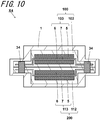
- the first inner container 102 and the second inner container 112 are welded in the welded portion 34 via the separator 7.
- the separator 7 which is a part of the first power generation element 103 is fixed to the first inner container 102 by the welded portion 34.
- the separator 7 which is a part of the second power generation element 113 is fixed to the second inner container 112 by the welded portion 34. Therefore, the possibility that the positions of the first power generation element 103 and the first inner container 102 are displaced can be reduced. In addition, the possibility that the positions of the second power generation element 113 and the second inner container 112 are displaced can be reduced. As a result, the reliability of the electrical connection of the first single cell 100 and the second single cell 200 can be improved.
- the number of single cells included in the electrochemical cell is not limited to two.
- the electrochemical cell may include three or more single cells.
- the welded portion may fix at least two of the three or more single cells.
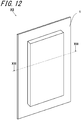
- An electrochemical cell X5 includes three single cells. The electrochemical cell X5 will be described in detail with reference to FIGS. 12 and 13 . In the electrochemical cell X5, a welded portion 44 fixes three single cells.
- the electrochemical cell X5 includes the first single cell 100, the second single cell 200, a third single cell 300, and the outer container 1 which accommodates the first single cell 100, the second cell 200, and the third single cell 300. Further, the first single cell 100, the second single cell 200, and the third single cell 300 are fixed by the welded portion 44.
- the electrochemical cell X5 is different from the electrochemical cell X4 in that the electrochemical cell X5 includes the third single cell 300.
- the configuration of the electrochemical cell X5 other than the above is the same as the electrochemical cell X4, and thus, the description thereof is omitted.
- the third single cell 300 includes a third power generation element 23 and a third inner container 22.
- the third power generation element 23 has the same shape as the first power generation element 103 and the second power generation element 113 in the electrochemical cell X5.
- the third power generation element 23 may have a shape different from those of the first power generation element 103 and the second power generation element 113.
- the materials used for the first power generation element 103 and the second power generation element 113 can be used. More specifically, the third power generation element 23 may be formed of, for example, the same material as the first power generation element 103 and the second power generation element 113.
- the first power generation element 103, the second power generation element 113, and the third power generation element 23 When viewed from the stacking direction of the first power generation element 103, the second power generation element 113, and the third power generation element 23, the first power generation element 103, the second power generation element 113, and the third power generation element 23 have a rectangular shape including long sides and short sides.
- the first power generation element 103, the second power generation element 113, and the third power generation element 23 are stacked so that the respective long sides and the respective short sides thereof correspond to each other.
- the third inner container 22 has the same shape as the first inner container 102 and the second inner container 112 in the electrochemical cell X5. However, the third inner container 22 may have a different shape from those of the first inner container 102 and the second inner container 112. As the third inner container 22, the materials used for the first inner container 102 and the second inner container 112 can be used. Specifically, the third inner container 22 may be formed of, for example, the same material as the first inner container 102 and the second inner container 112.
- the electrochemical cell X5 includes the welded portion 44 in which the first single cell 100, the second single cell 200, and the third single cell 300 are welded to each other.
- the welded portion 44 is provided to fix the first single cell 100, the second single cell 200, and the third single cell 300. More specifically, as shown in FIG. 13 , the welded portion 44 fixes the first single cell 100, the second single cell 200, and the third single cell 300 to each other. As a result, the first single cell 100, the second single cell 200, and the third single cell 300 can be fixed more firmly than when at least two single cells are fixed. Therefore, the reliability of the electrical connection of the electrochemical cell X5 can be improved.
- each single cell, each power generation element, each inner container, and each terminal are illustrated in the same shape so that the respective outer circumferences thereof correspond to each other.
- the outer circumferences thereof do not need to have the same shape and correspond to each other in the strict sense.
- the error of the first power generation element 103 and the second power generation element 113 is within 5 mm, they can be regarded as having the same shape and overlapping so that the respective outer circumferences thereof correspond to each other. This also applies to each single cell, each inner container, and each terminal.
Landscapes
- Chemical & Material Sciences (AREA)
- Chemical Kinetics & Catalysis (AREA)
- Electrochemistry (AREA)
- General Chemical & Material Sciences (AREA)
- Engineering & Computer Science (AREA)
- Manufacturing & Machinery (AREA)
- Connection Of Batteries Or Terminals (AREA)
- Sealing Battery Cases Or Jackets (AREA)
- Secondary Cells (AREA)
- Battery Mounting, Suspending (AREA)
- Laminated Bodies (AREA)
- Compositions Of Macromolecular Compounds (AREA)
- Manufacturing Of Printed Wiring (AREA)
Abstract
Description
- The present disclosure relates to an electrochemical cell.
- As the electrochemical cell, for example, the electrochemical cell described in Japanese Unexamined Patent Publication
JP-A 2013-48042 Patent Literature 1 includes a thin battery including a sheet-shaped electrode group, a non-aqueous electrolyte, and a first exterior body which hermetically accommodates the electrode group and the non-aqueous electrolyte, and a second exterior body which hermetically accommodates the thin battery. - An electrochemical cell of the disclosure includes a first single cell including a first power generation element and a first inner container which accommodates the first power generation element, a second single cell including a second power generation element and a second inner container which accommodates the second power generation element, and an outer container which accommodates the first single cell and the second single cell, and the first single cell and the second single cell are stacked, and the electrochemical cell further includes a welded portion in which the first inner container and the second inner container are welded to each other.
-
-
FIG. 1 shows a perspective view of an electrochemical cell X1; -
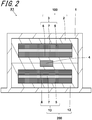
FIG. 2 shows a cross-sectional view of the electrochemical cell X1 ofFIG. 1 taken along the line II-II; -
FIG. 3 shows a perspective view of an electrochemical cell X2; -
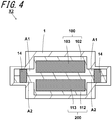
FIG. 4 shows a cross-sectional view of the electrochemical cell X2 ofFIG. 3 taken along the line IV-IV; -
FIG. 5 is a top view when a stack of a first single cell and a second single cell is taken out from an outer container of the electrochemical cell X2 and viewed from a stacking direction of the first single cell and the second single cell; -
FIG. 6 shows a perspective view of an electrochemical cell X3; -
FIG. 7 shows a cross-sectional view of the electrochemical cell X3 ofFIG. 6 taken along the line VII-VII; -
FIG. 8 is a top view when a stack of a first single cell and a second single cell is taken out from an outer container of the electrochemical cell X3 and viewed from a stacking direction of the first single cell and the second single cell; -
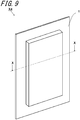
FIG. 9 shows a perspective view of an electrochemical cell X4; -
FIG. 10 shows a cross-sectional view of the electrochemical cell X4 ofFIG. 9 cut long line X-X; -
FIG. 11 is a top view when a stack of a first single cell and a second single cell is taken out from an outer container of the electrochemical cell X4 and viewed from a stacking direction of the first single cell and the second single cell; -
FIG. 12 shows a perspective view of an electrochemical cell X5; and -
FIG. 13 shows a cross-sectional view of the electrochemical cell X5 ofFIG. 12 taken along the line XIII-XIII. - An electrochemical cell X1 will be described in detail with reference to
FIGS. 1 and2 . As shown inFIGS. 1 and2 , the electrochemical cell X1 includes a firstsingle cell 100, a secondsingle cell 200, and anouter container 1 which accommodates the firstsingle cell 100 and the secondsingle cell 200. The firstsingle cell 100 and the secondsingle cell 200 are fixed by awelded portion 4. - The first
single cell 100 is a member of the smallest unit that functions as a battery in the electrochemical cell X1. The firstsingle cell 100 is, for example, a lithium ion battery. The firstsingle cell 100 includes a firstpower generation element 3, a firstinner container 2, and afirst terminal 8. The firstsingle cell 100 has, for example, a plate shape. The firstsingle cell 100 can conduct electricity to an external device by electrically connecting to the external device. - The first
power generation element 3 is a member for storing and releasing electricity by utilizing an electrochemical reaction. The firstpower generation element 3 includes, for example, apositive electrode 5, anegative electrode 6, and aseparator 7 located between thepositive electrode 5 and thenegative electrode 6. The firstpower generation element 3 can exchange cations and anions between thepositive electrode 5 and thenegative electrode 6 through theseparator 7. The firstpower generation element 3 can conduct electricity to an external device by electrically connecting thepositive electrode 5 and thenegative electrode 6 to the external device. - The first
power generation element 3 is, for example, a stack of thepositive electrode 5, theseparator 7, and thenegative electrode 6. The firstpower generation element 3 has, for example, a plate shape. In the firstpower generation element 3, for example, thepositive electrode 5, theseparator 7, and thenegative electrode 6 are stacked in a thickness direction of the plate shape. - The
positive electrode 5 and thenegative electrode 6 are, for example, electrochemically active substances. Thepositive electrode 5 and thenegative electrode 6 may include, for example, an active material and an electrolyte. As the electrolyte, for example, a solvent or a solvent mixture to which salt is added can be used. - Specifically, as the
positive electrode 5 and thenegative electrode 6, for example, the active substances and electrolytes described inUS Provisional Patent Application No. 61/787,382 US Provisional Patent Application No. 61/787,372 positive electrode 5 and thenegative electrode 6 may include additives, for example. - The
separator 7 is a member provided for exchanging cations and anions between thepositive electrode 5 and thenegative electrode 6. Theseparator 7 may be provided with, for example, fine holes through which cations and anions pass. For theseparator 7, for example, a porous insulating material can be used. Specifically, as theseparator 7, for example, polyolefin or polyvinyl chloride can be used. Since the firstpower generation element 3 includes theseparator 7, thepositive electrode 5 and thenegative electrode 6 can be electrically insulated from each other. - When the first
power generation element 3 has a plate shape, the firstpower generation element 3 can be set to, for example, 50 to 500 mm in length, 50 to 300 mm in width, and 0.1 to 2 mm in thickness. - The first
inner container 2 is a member provided with a space for wrapping the firstpower generation element 3 inside the firstinner container 2. The firstinner container 2 is provided to protect the firstpower generation element 3 from the external environment. More specifically, the firstinner container 2 is provided to protect the firstpower generation element 3 from oxygen and water in the air. The firstinner container 2 is provided to cover the entire firstpower generation element 3. The firstinner container 2 has, for example, a bag shape. The firstinner container 2 is formed, for example, by forming one member into a bag shape. The firstinner container 2 may be formed by welding two members, for example. The firstinner container 2 may have a rectangular shape, for example, when viewed from the stacking direction of thepositive electrode 5, theseparator 7, and thenegative electrode 6. - The first
inner container 2 includes, for example, an insulating material. As a result, the firstinner container 2 can restrain the external environment and the firstpower generation element 3 from being short-circuited. Therefore, the firstinner container 2 can protect the firstpower generation element 3 from the external environment. The firstinner container 2 includes, for example, a resin material. More specifically, as the resin material, for example, polyethylene terephthalate, polyethylene, or the like can be used. - In addition, the first
inner container 2 may have, for example, a multi-layer structure. The firstinner container 2 may have, for example, a two-layer structure. Specifically, the firstinner container 2 includes, for example, a thermosetting resin material and a heat-resistant resin material. The thermosetting resin material is specifically resin having a melting temperature of less than 100°C. The heat-resistant resin material is specifically resin having a melting temperature of 100°C or higher and 300°C or lower. As the heat-resistant resin material, for example, polyethylene terephthalate, polyethylene naphthalate, or the like can be used. As the thermosetting resin material, for example, polyethylene, polypropylene, or the like can be used. - In the case where the first
inner container 2 is rectangular when viewed from the stacking direction of the firstsingle cell 100 and the secondsingle cell 200, the firstinner container 2 can be set to, for example, 55 to 550 mm in length, 55 to 350 mm in width, and 0.1 to 2.2 mm in thickness. - The
first terminal 8 is provided to electrically connect a firstpower generation element 103 and an external device. Thefirst terminal 8 has, for example, a plate shape. Specifically, thefirst terminal 8 has, for example, a quadrangular shape when viewed from the stacking direction of the firstsingle cell 100 and the secondsingle cell 200. Thefirst terminal 8 may have a rectangular shape, for example. The rectangular shape mayinclude, for example, long sides and short sides. - When viewed from the stacking direction of the first
single cell 100 and the secondsingle cell 200, thefirst terminal 8 is in contact with the firstpower generation element 103. When viewed from the stacking direction of the firstsingle cell 100 and the secondsingle cell 200, thefirst terminal 8 is located on any side of an outer circumference of the firstpower generation element 103. Thefirst terminal 8 extends outwardly from the firstinner container 102 in order to be electrically connected to an external device. Thefirst terminal 8 is electrically connected to an external connection terminal outside the firstinner container 102. - The
first terminal 8 is, for example, a conductive member. Thefirst terminal 8 may include, for example, a metal material. More specifically, as the metal material, for example, aluminum, copper, or the like can be used. - When the
first terminal 8 has a plate shape, thefirst terminal 8 can be set to, for example, 30 to 100 mm in length, 10 to 100 mm in width, and 0.1 to 0.5 mm in thickness. - Like the first
single cell 100, the secondsingle cell 200 is provided for passing electricity to an external device. In the electrochemical cell X1, the firstsingle cell 100 and the secondsingle cell 200 are connected in parallel. As a result, the capacity of the electrochemical cell X1 can be increased. The firstsingle cell 100 and the secondsingle cell 200 may be connected in series. As a result, the voltage of the electrochemical cell X1 can be increased. - The second
single cell 200 is stacked on the firstsingle cell 100 in theouter container 1. The secondsingle cell 200 includes a secondpower generation element 13 and a secondinner container 12. The secondsingle cell 200 has the same shape as the firstsingle cell 100 in the electrochemical cell X1. However, the secondsingle cell 200 may have a shape different from that of the firstsingle cell 100, for example. In the electrochemical cell X1, the secondsingle cell 200 is stacked with the firstsingle cell 100 so that an outer circumferences thereof correspond to each other. However, the secondsingle cell 200 may be stacked with the firstsingle cell 100 without aligning an outer circumference thereof. - As the second
power generation element 13, for example, the material used for the firstpower generation element 3 can be used. More specifically, the secondpower generation element 13 may be formed of, for example, the same material as the firstpower generation element 3. As the secondpower generation element 13, for example, a material different from that of the firstpower generation element 3 may be used. - The second
inner container 12 has the same shape as the firstinner container 2 in the electrochemical cell X1. However, the secondinner container 12 may have a different shape from the firstinner container 2, for example. As the secondinner container 12, for example, the material used for the firstinner container 2 can be used. More specifically, the secondinner container 12 may use the same material as the firstinner container 2. As the secondinner container 12, for example, a material different from that of the firstinner container 2 may be used. - The second
single cell 200 can be set to the same dimensions as the firstsingle cell 100, for example. The secondsingle cell 200 may have different dimensions from the firstsingle cell 100, for example. - The
outer container 1 is a member provided with a space for wrapping the firstsingle cell 100 and the secondsingle cell 200 inside theouter container 1. Theouter container 1 is a member for protecting the firstsingle cell 100 and the secondsingle cell 200 from the external environment. More specifically, theouter container 1 is a member for protecting the firstsingle cell 100 and the secondsingle cell 200 from oxygen and moisture in the air. Theouter container 1 has, for example, a bag shape. Theouter container 1 is formed, for example, by forming one member into a bag shape. Theouter container 1 may be formed by welding two members, for example. Theouter container 1 may have a rectangular shape when viewed from the stacking direction of the firstsingle cell 100 and the secondsingle cell 200. - The
outer container 1 includes, for example, an insulating material. As a result, theouter container 1 can restrain the external environment, and the firstsingle cell 100 and the secondsingle cell 200 from being short-circuited. Therefore, theouter container 1 can protect the firstsingle cell 100 and the secondsingle cell 200 from the external environment. As the insulating material, for example, a resin material can be used. More specifically, as the resin material, for example, polyethylene terephthalate, polyethylene, or the like can be used. - The
outer container 1 has, for example, a multi-layer structure. Theouter container 1 may have, for example, a three-layer structure. Specifically, theouter container 1 may include, for example, a first insulating layer, a moisture-proof layer, and a second insulating layer. Here, the moisture-proof layer is located between, for example, the first insulating layer and the second insulating layer. Specifically, the moisture-proof layer may be covered with, for example, the first insulating layer and the second insulating layer. - The first insulating layer includes, for example, a resin material. Specifically, as the resin material, for example, polyethylene terephthalate, polyethylene naphthalate, or the like can be used.
- The moisture-proof layer is provided to restrain oxygen and water that permeated the first resin layer from reaching the second resin layer. The moisture-proof layer includes, for example, a metal material. Specifically, as the metal material, for example, aluminum, copper, or the like can be used.
- The second resin layer includes, for example, a resin material. Specifically, as the resin material, for example, polyethylene, polypropylene, or the like can be used.
- Since the
outer container 1 includes the moisture-proof layer, the firstsingle cell 100 and the secondsingle cell 200 can be protected from oxygen and water that permeated the first resin layer. As a result, the possibility that the firstsingle cell 100 and the secondsingle cell 200 are damaged can be reduced. - In the case where the
outer container 1 is rectangular when viewed from the stacking direction of the firstsingle cell 100 and the secondsingle cell 200, it can be set to, for example, 60 to 600 mm in length, 60 to 400 mm in width, and 1 to 20 mm in thickness. - The welded
portion 4 is a portion where the firstinner container 2 and the secondinner container 12 are welded to each other. The weldedportion 4 is provided to fix the firstsingle cell 100 and the secondsingle cell 200. In the weldedportion 4, for example, the material of the firstinner container 2 and the material of the secondinner container 12 may be diffused from each other. In the weldedportion 4, for example, the material of the firstinner container 2 and the material of the secondinner container 12 may be entangled with each other. The weldedportion 4 may include, for example, a crystalline portion in which the molecules of the material of the firstinner container 2 and the molecules of the material of the secondinner container 12 are aligned according to a certain rule. - As shown in
FIG. 2 , the firstinner container 2 and the secondinner container 12 are welded, so that the firstsingle cell 100 and the secondsingle cell 200 are fixed in theouter container 1. Therefore, the possibility that the positions of the firstsingle cell 100 and the secondsingle cell 200 are displaced is reduced without increasing the size of the electrochemical cell X1. As a result, it is possible to reduce the possibility that the reliability of the electrical connection of the electrochemical cell X1 is impaired and also the possibility that the thickness is partially increased at the fixed portion. - As shown in
FIG. 2 , the weldedportion 4 is located between, for example, the firstpower generation element 3 and the secondpower generation element 13. The weldedportion 4 has, for example, a plate shape. The weldedportion 4 is, for example, strip-shaped when viewed from the stacking direction of the firstsingle cell 100 and the secondsingle cell 200. The weldedportion 4 may have a quadrangular shape, for example. When the weldedportion 4 has a quadrangular shape, for example, the corners of the quadrangular shape may be rounded. As a result, the external force becomes difficult to concentrate on the corners of the quadrangular weldedportion 4 and the possibility that the weldedportion 4 is damaged can be reduced. - The welded
portion 4 has, for example, an insulating material. As the insulating material, for example, a resin material can be used. Specifically, for example, polyethylene terephthalate, polyethylene, or the like may be used as the weldedportion 4. - In addition, as the welded
portion 4, for example, a material whose light transmittance changes when welded can be used. As a result, the weldedportion 4 can be easily visually confirmed. As the weldedportion 4, for example, a material whose hardness increases when welded may be used. Therefore, the possibility that the electrochemical cell X1 is deformed by receiving an external force can be reduced. As a result, the reliability of the electrical connection of the electrochemical cell X1 can be improved. - When the welded
portion 4 has a plate shape, it can be set to, for example, 1 to 100 mm in length, 1 to 20 mm in width, and 0.02 to 1 mm in thickness. - The welded
portion 4 is formed by, for example, ultrasonically welding the firstinner container 2 and the secondinner container 12. The method of ultrasonic welding will be described more specifically below. First, the firstinner container 2 and the secondinner container 12 are fixed on a table, and a horn is brought into contact with the position where the firstinner container 2 and the secondinner container 12 are to be welded to each other. The horn referred to here is, for example, a member that vibrates at a frequency of 20 to 40 kHz. The horn includes a head portion that comes into contact with a welding position and a connection portion that transmits vibration to the head portion. Specifically, the head portion has a rectangular shape when viewed from the stacking direction of the firstinner container 2 and the secondinner container 12, for example. The head portion may have a square shape, for example. - Next, the horn is vibrated to give vibration energy to the first
inner container 2 and the secondinner container 12. The vibration energy transmitted from the horn melts the interface where the firstinner container 2 and the secondinner container 12 come into contact with each other. After that, the weldedportion 4 is formed by cooling the melted portion of the firstinner container 2 and the secondinner container 12 while applying pressure. - In addition, the welded
portion 4 may be formed by, for example, heat-sealing the firstinner container 2 and the secondinner container 12. The heat sealing method will be specifically described below. First, the heated metal plate is brought into contact with the position where the firstinner container 2 and the secondinner container 12 are to be welded. Next, the firstinner container 2 and the secondinner container 12 are applied with heat and melted. After that, the weldedportion 4 is formed by cooling the portion where the firstinner container 2 and the secondinner container 12 are melted. - The metal plate is heated to, for example, 100 to 200°C. The metal plate has, for example, a plate shape. Specifically, the metal plate has a rectangular shape when viewed from the stacking direction of the first
inner container 2 and the secondinner container 12. The metal plate may have a square shape, for example. - The welded
portion 4 may be formed by any method without being limited to the methods of ultrasonic welding and heat sealing. - An electrochemical cell X2 will be described in detail with reference to
FIGS. 3 to 5 . As shown inFIGS. 3 and4 , the electrochemical cell X2 includes the firstsingle cell 100, the secondsingle cell 200, and theouter container 1 which accommodates the firstsingle cell 100 and the secondsingle cell 200. The firstsingle cell 100 and the secondsingle cell 200 are fixed by a weldedportion 14. - The electrochemical cell X2 is different from the electrochemical cell X1 in the shape of a first
power generation element 103, the shape of a firstinner container 102, the shape of a secondpower generation element 113, and the shape of a secondinner container 112. Further, the electrochemical cell X2 is different from the electrochemical cell X1 in the position and shape of the weldedportion 14. The others are the same as those of the electrochemical cell X1, and thus, the description thereof is omitted. - The first
single cell 100 includes the firstpower generation element 103 and the firstinner container 102. The firstpower generation element 103 has, for example, a rectangular shape when viewed from the stacking direction of the firstsingle cell 100 and the secondsingle cell 200. More specifically, the firstpower generation element 103 may have, for example, a rectangular shape including long sides and short sides. - The first
inner container 102 has, for example, a rectangular shape when viewed from the stacking direction of the firstsingle cell 100 and the secondsingle cell 200. More specifically, the firstinner container 102 may have, for example, a rectangular shape including long sides and short sides. The firstinner container 102 includes a first peripheral edge portion A1. The first peripheral edge portion A1 is a portion located on a periphery of the firstinner container 102. Specifically, the first peripheral edge portion A1 means a region extending from an outer circumference of the firstinner container 102 to an outer circumference of the firstpower generation element 103 when viewed from the stacking direction of the firstsingle cell 100 and the secondsingle cell 200. That is, the first peripheral edge portion A1 is a region where the firstpower generation element 103 and the firstinner container 102 do not overlap with each other. - The second
single cell 200 includes the secondpower generation element 113 and the secondinner container 112. The secondpower generation element 113 has the same shape as the firstpower generation element 103 in the electrochemical cell X2. However, the firstpower generation element 103 and the secondpower generation element 113 may have different shapes. As the secondpower generation element 113, the material used in the firstpower generation element 103 can be used. More specifically, the secondpower generation element 113 may be formed of, for example, the same material as the firstpower generation element 103. - The second
inner container 112 has the same shape as the firstinner container 102 in the electrochemical cell X2. However, the secondinner container 112 and the firstinner container 102 may have different shapes, for example. As the secondinner container 112, the material used for the firstinner container 102 can be used. Specifically, the secondinner container 112 may be formed of the same material as the firstinner container 102, for example. The secondinner container 112 includes a second peripheral edge portion A2. The second peripheral edge portion A2 is a portion located on a periphery of the secondinner container 112. Specifically, the second peripheral edge portion A2 means a region extending from an outer circumference of the secondinner container 112 to an outer circumference of the secondpower generation element 113 when viewed from the stacking direction of the firstsingle cell 100 and the secondsingle cell 200. That is, it is a region where the secondpower generation element 113 and the secondinner container 112 do not overlap with each other. - The first
power generation element 103 and the secondpower generation element 113 are stacked so that the respective long sides and the respective short sides thereof correspond to each other when viewed from the stacking direction of the firstsingle cell 100 and the secondsingle cell 200. The firstinner container 102 and the secondinner container 112 are stacked so that the respective long sides and the respective short sides thereof correspond to each other when viewed from the stacking direction of the firstsingle cell 100 and the secondsingle cell 200. - In
FIG. 4 , thepositive electrodes 5, theseparators 7, and thenegative electrodes 6 of the firstpower generation element 103 and the secondpower generation element 113 are omitted. - As shown in
FIG. 4 , in the weldedportion 14, the first peripheral edge portion A1 and the second peripheral edge portion A2 are welded to each other. As a result, as compared with the case where the weldedportion 14 is located at the portion where the firstinner container 102 and the secondinner container 112, and the firstpower generation element 103 and the secondpower generation element 113 overlap, a gap can be provided between the weldedportion 14, and the firstpower generation element 103 and the secondpower generation element 113. Therefore, in the weldedportion 14, the influence of thermal stress due to the heat generated from the firstpower generation element 103 and the secondpower generation element 113 can be reduced. As a result, the possibility that the weldedportion 14 is damaged can be reduced. -
FIG. 5 shows a top view when the stack of the firstsingle cell 100 and the secondsingle cell 200 is taken out from theouter container 1 of the electrochemical cell X2 and viewed from the stacking direction of the firstsingle cell 100 and the secondsingle cell 200. The outer circumferences of the firstpower generation element 103 and the secondpower generation element 113 when viewed from the stacking direction of the firstpower generation element 103 and the secondpower generation element 113 through the firstinner container 102 and the secondinner container 112 are indicated by dotted lines. The extension lines of the long sides of the firstpower generation element 103 and the secondpower generation element 113 are indicated by alternate long and short dash lines as virtual lines. - As shown in
FIGS. 4 and5 , a plurality of weldedportions 14 may be provided. As a result, the plurality of weldedportions 14 can disperse the external force to the plurality of weldedportions 14. Therefore, the external force becomes difficult to concentrate on one weldedportion 14. As a result, the possibility that the weldedportion 14 is damaged can be reduced. - As shown in
FIG. 5 , the weldedportion 14 may be located along each long side of the firstpower generation element 103 and the secondpower generation element 113. The weldedportion 14 may be located along an extension line of each long side of the firstpower generation element 103 and the secondpower generation element 113. As a result, by locating the welded portion along the long side that is susceptible to the external force, the possibility that the firstsingle cell 100 or the secondsingle cell 200 is displaced in the short side direction is reduced. As a result, the reliability of the electrical connection of the electrochemical cell can be improved. - In addition, when viewed from the stacking direction of the first
single cell 100 and the secondsingle cell 200, the weldedportion 14 has, for example, a quadrangular shape. Specifically, the weldedportion 14 may be, for example, a rectangular shape including long sides. Here, the long sides of the weldedportion 14 may be along the long sides of the firstpower generation element 103. As a result, the welded portion can be positioned along the long side that is susceptible to the external force. Therefore, the possibility that the firstsingle cell 100 or the secondsingle cell 200 is displaced in the short side direction can be reduced. As a result, the reliability of the electrical connection of the electrochemical cell can be improved. - An electrochemical cell X3 will be described in detail with reference to
FIGS. 6 to 8 . As shown inFIGS. 6 and7 , the electrochemical cell X3 includes the firstsingle cell 100, the secondsingle cell 200, and theouter container 1 which accommodates the firstsingle cell 100 and the secondsingle cell 200. Further, the firstsingle cell 100 and the secondsingle cell 200 are fixed by a weldedportion 24. The electrochemical cell X3 is different from the electrochemical cell X2 in that the position of the weldedportion 24 is different and that the weldedportion 24 includes aconvex portion 9. The others are the same as those of the electrochemical cell X2, and thus, the description thereof is omitted. - Similarly to
FIG. 5 ,FIG. 8 shows a top view when the stack of the firstsingle cell 100 and the secondsingle cell 200, in which the respective long sides and the respective short sides thereof correspond to each other, is taken out from theouter container 1 of the electrochemical cell X3 and viewed from the stacking direction of the firstsingle cell 100 and the secondsingle cell 200. The extension lines of the respective long sides and the respective short sides of the firstpower generation element 103 and the secondpower generation element 113 are indicated as alternate long and short dash lines as virtual lines. - As shown in
FIG. 8 , the weldedportion 24 may be located at the four corners of the first peripheral edge portion A1 and the second peripheral edge portion A2 when viewed from the stacking direction of the firstsingle cell 100 and the secondsingle cell 200. More specifically, the four corners of the first peripheral edge portion A1 and the second peripheral edge portion A2 mean a region surrounded by the extension lines of the respective long sides of the firstpower generation element 103 and the secondpower generation element 113, the extension lines of the respective short sides of the firstpower generation element 103 and the secondpower generation element 113, and the outer circumferences of the firstinner container 102 and the secondinner container 112. As a result, the firstsingle cell 100 and the secondsingle cell 200 can be made difficult to be deformed in the four corner regions of the firstsingle cell 100 and the secondsingle cell 200 where the external force is easily concentrated. As a result, the reliability of the electrical connection of the electrochemical cell can be improved. - In addition, as shown in
FIGS. 7 and8 , the weldedportion 24 includes theconvex portion 9. Theconvex portion 9 is provided to disperse the external force applied to the weldedportion 24 to theconvex portion 9 itself. As a result, the possibility that the weldedportion 24 is damaged can be reduced. Theconvex portion 9 is provided at a position adjacent to the weldedportion 24, for example. Specifically, theconvex portion 9 may be located along an outer circumference of the weldedportion 24, for example. - In the electrochemical cell X3, the
convex portion 9 is linear. More specifically, theconvex portion 9 has a frame shape when viewed from the stacking direction of the firstsingle cell 100 and the secondsingle cell 200. As shown inFIG. 7 , the cross section of theconvex portion 9 has a semicircular shape. - The
convex portion 9 includes, for example, an insulating material. As the insulating material, for example, a resin material may be used. More specifically, as the resin material, for example, polyethylene terephthalate, polyethylene, or the like may be used. - In addition, the
convex portion 9 can be formed of the same material as the weldedportion 24. Therefore, coefficients of thermal expansion of theconvex portion 9 and the weldedportion 24 can be made the same. As a result, the possibility that theconvex portion 9 and the weldedportion 24 are separated due to the difference in the coefficient of thermal expansion can be reduced. Theconvex portion 9 may be formed at the same time as forming the weldedportion 24, for example. - In addition, the
convex portion 9 may be formed of, for example, a material different from that of the weldedportion 24. More specifically, theconvex portion 9 may have a higher elastic modulus than that of the weldedportion 24. As a result, when an external force is applied to theconvex portion 9, theconvex portion 9 is deformed, so that the external force becomes difficult to be transmitted to the weldedportion 24. Therefore, the possibility that the weldedportion 24 is damaged can be reduced. - In addition, a plurality of
convex portions 9 may be provided for one weldedportion 24, for example. As a result, the external force can be dispersed to the plurality ofconvex portions 9, so that the external force is less likely to be concentrated on oneconvex portion 9. Therefore, the possibility that theconvex portion 9 is damaged can be reduced. - In the case where the
convex portion 9 is linear when viewed from the stacking direction of the firstsingle cell 100 and the secondsingle cell 200, theconvex portion 9 can be set to, for example, 1 to 50 mm in length, 1 to 10 mm in width, and 0.1 to 5 mm in thickness. - An electrochemical cell X4 will be described in detail with reference to
FIGS. 9 to 11 . The electrochemical cell X4 is different from the electrochemical cell X3 in that the firstsingle cell 100 includes thefirst terminal 8 and the secondsingle cell 200 includes asecond terminal 18. Further, the electrochemical cell X4 is different from the electrochemical cell X3 in that the position of a weldedportion 34 is different. The others are the same as those of the electrochemical cell X3, and thus, the description thereof is omitted. - As in
FIG. 8 ,FIG. 11 shows a top view when the stack of the firstsingle cell 100 and the secondsingle cell 200, in which the respective long sides and the respective short sides thereof correspond to each other, is taken out from theouter container 1 of the electrochemical cell X4 and viewed from the stacking direction of the firstsingle cell 100 and the secondsingle cell 200. - When viewed from the stacking direction of the first
single cell 100 and the secondsingle cell 200, the firstpower generation element 103 includes thefirst terminal 8 extending outwardly from a side thereof. Thefirst terminal 8 is provided to electrically connect the firstpower generation element 103 and an external device. Thefirst terminal 8 has, for example, a plate shape. Specifically, thefirst terminal 8 has a quadrangular shape when viewed from the stacking direction of the firstsingle cell 100 and the secondsingle cell 200, for example. Thefirst terminal 8 may have a rectangular shape, for example. Specifically, the rectangular shape may include long sides and short sides, for example. - In the electrochemical cell X4, the
first terminal 8 is in contact with the firstpower generation element 103 when viewed from the stacking direction of the firstsingle cell 100 and the secondsingle cell 200. When viewed from the stacking direction of the firstsingle cell 100 and the secondsingle cell 200, thefirst terminal 8 is located on any side of the outer circumference of the firstpower generation element 103. In addition, thefirst terminal 8 extends outside the firstinner container 102 in order to be electrically connected to an external device. - The
first terminal 8 is, for example, a conductive member. Thefirst terminal 8 may include, for example, a metal material. More specifically, as the metal material, for example, aluminum, copper, or the like can be used. - When the
first terminal 8 has a plate shape, it can be set to, for example, 30 to 100 mm in length, 10 to 100 mm in width, and 0.1 to 0.5 mm in thickness. - When viewed from the stacking direction of the first
single cell 100 and the secondsingle cell 200, the secondpower generation element 113 includes thesecond terminal 18 extending outwardly from a side thereof. In the electrochemical cell X4, thesecond terminal 18 has the same shape as thefirst terminal 8. However, thesecond terminal 18 may have a shape different from that of thefirst terminal 8, for example. In addition, the material used for thefirst terminal 8 can be used for thesecond terminal 18. Specifically, thesecond terminal 18 may be formed of the same material as thefirst terminal 8, for example. - In the electrochemical cell X4, the
second terminal 18 is located on any side of the outer circumference of the firstpower generation element 103 when viewed from the stacking direction of the firstsingle cell 100 and the secondsingle cell 200. In addition, thesecond terminal 18 extends outside the secondinner container 112 in order to be electrically connected to an external device. In the electrochemical cell X4, when viewed from the stacking direction of the firstsingle cell 100 and the secondsingle cell 200, thesecond terminal 18 overlaps thefirst terminal 8 so that the outer circumferences thereof correspond to each other. InFIG. 11 , the overlapping portions of thefirst terminal 8 and thesecond terminal 18, and the firstinner container 102 and the secondinner container 112 when viewed from the stacking direction of the firstsingle cell 100 and the secondsingle cell 200, are indicated by dotted lines. - When viewed from the stacking direction, the first
power generation element 103 includes a terminal extending outwardly from a side thereof, and the secondpower generation element 113 includes a terminal extending outwardly from a side thereof. Then, the weldedportion 34 may be located along a side where the respective terminals are not located. As a result, when the shaking is transmitted to the electrochemical cell X4 from the outside, the influence of the external force applied to the electrochemical cell X4 at a position away from each terminal fixed to the external device can be reduced. - In the electrochemical cell X4, as shown in
FIG. 11 , when viewed from the stacking direction of the firstsingle cell 100 and the secondsingle cell 200, the weldedportion 34 is located along the outer peripheral sides of the firstpower generation element 103 and the secondpower generation element 113 where thefirst terminal 8 and thesecond terminal 18 are not located. More specifically, the outer peripheral sides of the firstpower generation element 103 and the secondpower generation element 113 where thefirst terminal 8 and thesecond terminal 18 are not located mean the sides where the outer peripheral sides of the firstpower generation element 103 and the secondpower generation element 113 do not overlap with thefirst terminal 8 and thesecond terminal 18. Therefore, by locating the weldedportion 34 along the sides where thefirst terminal 8 and thesecond terminal 18 are not located, the firstsingle cell 100 and the secondsingle cell 200 can be fixed at a position away from thefirst terminal 8 and thesecond terminal 18. Therefore, the influence of the external force applied to the firstsingle cell 100 and the secondsingle cell 200 can be reduced. As a result, the reliability of the electrical connection of the electrochemical cell X4 can be improved. - As shown in
FIG. 10 , in the electrochemical cell X4, the firstinner container 102 and the secondinner container 112 are welded in the weldedportion 34 via theseparator 7. Here, theseparator 7 which is a part of the firstpower generation element 103 is fixed to the firstinner container 102 by the weldedportion 34. Theseparator 7 which is a part of the secondpower generation element 113 is fixed to the secondinner container 112 by the weldedportion 34. Therefore, the possibility that the positions of the firstpower generation element 103 and the firstinner container 102 are displaced can be reduced. In addition, the possibility that the positions of the secondpower generation element 113 and the secondinner container 112 are displaced can be reduced. As a result, the reliability of the electrical connection of the firstsingle cell 100 and the secondsingle cell 200 can be improved. - The number of single cells included in the electrochemical cell is not limited to two. The electrochemical cell may include three or more single cells. Here, the welded portion may fix at least two of the three or more single cells. An electrochemical cell X5 includes three single cells. The electrochemical cell X5 will be described in detail with reference to
FIGS. 12 and13 . In the electrochemical cell X5, a weldedportion 44 fixes three single cells. - As shown in
FIGS. 12 and13 , the electrochemical cell X5 includes the firstsingle cell 100, the secondsingle cell 200, a thirdsingle cell 300, and theouter container 1 which accommodates the firstsingle cell 100, thesecond cell 200, and the thirdsingle cell 300. Further, the firstsingle cell 100, the secondsingle cell 200, and the thirdsingle cell 300 are fixed by the weldedportion 44. - The electrochemical cell X5 is different from the electrochemical cell X4 in that the electrochemical cell X5 includes the third
single cell 300. The configuration of the electrochemical cell X5 other than the above is the same as the electrochemical cell X4, and thus, the description thereof is omitted. - The third
single cell 300 includes a thirdpower generation element 23 and a thirdinner container 22. The thirdpower generation element 23 has the same shape as the firstpower generation element 103 and the secondpower generation element 113 in the electrochemical cell X5. However, the thirdpower generation element 23 may have a shape different from those of the firstpower generation element 103 and the secondpower generation element 113. As the thirdpower generation element 23, the materials used for the firstpower generation element 103 and the secondpower generation element 113 can be used. More specifically, the thirdpower generation element 23 may be formed of, for example, the same material as the firstpower generation element 103 and the secondpower generation element 113. When viewed from the stacking direction of the firstpower generation element 103, the secondpower generation element 113, and the thirdpower generation element 23, the firstpower generation element 103, the secondpower generation element 113, and the thirdpower generation element 23 have a rectangular shape including long sides and short sides. The firstpower generation element 103, the secondpower generation element 113, and the thirdpower generation element 23 are stacked so that the respective long sides and the respective short sides thereof correspond to each other. - The third
inner container 22 has the same shape as the firstinner container 102 and the secondinner container 112 in the electrochemical cell X5. However, the thirdinner container 22 may have a different shape from those of the firstinner container 102 and the secondinner container 112. As the thirdinner container 22, the materials used for the firstinner container 102 and the secondinner container 112 can be used. Specifically, the thirdinner container 22 may be formed of, for example, the same material as the firstinner container 102 and the secondinner container 112. - The electrochemical cell X5 includes the welded
portion 44 in which the firstsingle cell 100, the secondsingle cell 200, and the thirdsingle cell 300 are welded to each other. The weldedportion 44 is provided to fix the firstsingle cell 100, the secondsingle cell 200, and the thirdsingle cell 300. More specifically, as shown inFIG. 13 , the weldedportion 44 fixes the firstsingle cell 100, the secondsingle cell 200, and the thirdsingle cell 300 to each other. As a result, the firstsingle cell 100, the secondsingle cell 200, and the thirdsingle cell 300 can be fixed more firmly than when at least two single cells are fixed. Therefore, the reliability of the electrical connection of the electrochemical cell X5 can be improved. - For the sake of simplicity, in
FIGS. 1 to 13 , each single cell, each power generation element, each inner container, and each terminal are illustrated in the same shape so that the respective outer circumferences thereof correspond to each other. However, the outer circumferences thereof do not need to have the same shape and correspond to each other in the strict sense. For example, if the error of the firstpower generation element 103 and the secondpower generation element 113 is within 5 mm, they can be regarded as having the same shape and overlapping so that the respective outer circumferences thereof correspond to each other. This also applies to each single cell, each inner container, and each terminal. -
- X1 to X5: Electrochemical cell
- 1: Outer container
- 2, 102: First inner container
- 3, 103: First power generation element
- 4, 14, 24, 34, 44: Welded portion
- 5: Positive electrode
- 6: Negative electrode
- 7: Separator
- 8: First terminal
- 9: Convex portion
- 12, 112: Second inner container
- 13, 113: Second power generation element
- 18: Second terminal
- 22: Third inner container
- 23: Third power generation element
- 28: Third terminal
- 100: First single cell
- 200: Second single cell
- 300: Third single cell
- A1: First peripheral edge portion
- A2: Second peripheral edge portion
Claims (7)
- An electrochemical cell, comprising:a first single cell comprising a first power generation element and a first inner container which accommodates the first power generation element;a second single cell comprising a second power generation element and a second inner container which accommodates the second power generation element; andan outer container which accommodates the first single cell and the second single cell,the first single cell and the second single cell being stacked, andthe electrochemical cell comprising at least one welded portion in which the first inner container and the second inner container are welded to each other.
- The electrochemical cell according to claim 1, wherein the at least one welded portion comprises a plurality of welded portions.
- The electrochemical cell according to claim 1 or 2, wherein
when viewed from a stacking direction of the first single cell and the second single cell,
entirety of the first power generation element is located inside an outer circumference of the first inner container, and the first inner container comprises a first peripheral edge portion which does not overlap with the first power generation element,
entirety of the second power generation element is located inside an outer circumference of the second inner container, and the second inner container comprises a second peripheral edge portion which does not overlap with the first power generation element, and
in the at least one welded portion, the first peripheral edge portion and the second peripheral edge portion are welded to each other. - The electrochemical cell according to claim 3, wherein
when viewed from the stacking direction,
the first power generation element and the second power generation element are of a same rectangular shape and are overlapped with each other so that respective long sides and short sides thereof correspond to each other, and
the at least one welded portion is located along the respective long sides or extension lines of the respective long sides. - The electrochemical cell according to claim 3 or 4, wherein
when viewed from the stacking direction,
the first power generation element and the second power generation element are of a same rectangular shape and are overlapped with each other so that respective long sides and short sides thereof correspond to each other, and
the at least one welded portion is of a rectangular shape along the respective long sides or extension lines of the respective long sides. - The electrochemical cell according to claim 4 or 5, wherein
when viewed from the stacking direction,
the at least one welded portion is located in a region surrounded by the extension lines of the long sides of the first power generation element, the extension lines of the short sides of the first power generation element, and the outer circumference of the first inner container. - The electrochemical cell according to any one of claims 1 to 3, wherein
when viewed from the stacking direction,
the first power generation element includes a terminal extending outwardly from a side thereof, and the second power generation element includes a terminal extending outwardly from a side thereof, and
the at least one welded portion is located along sides of the first power generation element and the second power generation element where the respective terminals are not located.
Applications Claiming Priority (2)
| Application Number | Priority Date | Filing Date | Title |
|---|---|---|---|
| JP2018121980 | 2018-06-27 | ||
| PCT/JP2019/025368 WO2020004458A1 (en) | 2018-06-27 | 2019-06-26 | Electrochemical cell |
Publications (2)
| Publication Number | Publication Date |
|---|---|
| EP3817084A1 true EP3817084A1 (en) | 2021-05-05 |
| EP3817084A4 EP3817084A4 (en) | 2022-03-09 |
Family
ID=68986543
Family Applications (1)
| Application Number | Title | Priority Date | Filing Date |
|---|---|---|---|
| EP19825860.0A Pending EP3817084A4 (en) | 2018-06-27 | 2019-06-26 | Electrochemical cell |
Country Status (5)
| Country | Link |
|---|---|
| US (1) | US11764443B2 (en) |
| EP (1) | EP3817084A4 (en) |
| JP (3) | JP7119088B2 (en) |
| CN (2) | CN112074967A (en) |
| WO (1) | WO2020004458A1 (en) |
Families Citing this family (1)
| Publication number | Priority date | Publication date | Assignee | Title |
|---|---|---|---|---|
| JPWO2022215342A1 (en) * | 2021-04-09 | 2022-10-13 |
Family Cites Families (19)
| Publication number | Priority date | Publication date | Assignee | Title |
|---|---|---|---|---|
| JPH04104455A (en) * | 1990-08-22 | 1992-04-06 | Shin Kobe Electric Mach Co Ltd | Sealed lead-acid battery |
| JP3964521B2 (en) | 1997-12-02 | 2007-08-22 | 株式会社東芝 | Assembled battery |
| JP2002100341A (en) | 2000-09-21 | 2002-04-05 | Denso Corp | Battery |
| JP4203261B2 (en) | 2002-05-21 | 2008-12-24 | 日産自動車株式会社 | Secondary battery module |
| JP2004055153A (en) | 2002-07-16 | 2004-02-19 | Nissan Motor Co Ltd | Stacked battery |
| JP4359809B2 (en) * | 2002-08-05 | 2009-11-11 | トヨタ自動車株式会社 | Storage element module and manufacturing method thereof |
| CN1331249C (en) * | 2002-12-25 | 2007-08-08 | 富士重工业株式会社 | Storage battery |
| JP2006172994A (en) | 2004-12-17 | 2006-06-29 | Nissan Motor Co Ltd | Assembled battery and manufacturing method of assembled battery |
| KR100870355B1 (en) * | 2007-07-19 | 2008-11-25 | 삼성에스디아이 주식회사 | Pouch Type Battery Pack |
| DE102009031014A1 (en) | 2009-06-29 | 2010-12-30 | Li-Tec Battery Gmbh | Method of making a battery assembly |
| KR101259442B1 (en) | 2011-07-01 | 2013-05-31 | 지에스나노텍 주식회사 | Method for packaging thin film cells and apparatus for packaging thin film cells |
| JP5838323B2 (en) | 2011-08-29 | 2016-01-06 | パナソニックIpマネジメント株式会社 | Battery packaging |
| WO2013042612A1 (en) * | 2011-09-21 | 2013-03-28 | Necエナジーデバイス株式会社 | Film sheath battery and assembled battery |
| JP2014078498A (en) * | 2012-09-19 | 2014-05-01 | Toshiba Corp | Battery module |
| JP2015179618A (en) * | 2014-03-19 | 2015-10-08 | 凸版印刷株式会社 | Outer case, laminate film for outer case, and battery module |
| JP2018113097A (en) * | 2015-05-21 | 2018-07-19 | パナソニックIpマネジメント株式会社 | Assembled battery |
| EP4668405A3 (en) * | 2015-06-18 | 2026-03-25 | 24M Technologies, Inc. | Single pouch battery cells and methods of manufacture |
| JP2017130378A (en) * | 2016-01-21 | 2017-07-27 | トヨタ自動車株式会社 | Laminate battery module |
| JP6743664B2 (en) | 2016-11-18 | 2020-08-19 | 株式会社Gsユアサ | Power storage device and method of manufacturing power storage device |
-
2019
- 2019-06-26 US US17/252,730 patent/US11764443B2/en active Active
- 2019-06-26 JP JP2020527573A patent/JP7119088B2/en active Active
- 2019-06-26 WO PCT/JP2019/025368 patent/WO2020004458A1/en not_active Ceased
- 2019-06-26 EP EP19825860.0A patent/EP3817084A4/en active Pending
- 2019-06-26 CN CN201980030018.7A patent/CN112074967A/en active Pending
- 2019-06-26 CN CN202411156632.7A patent/CN119050606A/en active Pending
-
2022
- 2022-08-03 JP JP2022124369A patent/JP7480230B2/en active Active
-
2024
- 2024-04-24 JP JP2024070980A patent/JP2024099715A/en active Pending
Also Published As
| Publication number | Publication date |
|---|---|
| CN112074967A (en) | 2020-12-11 |
| US20210218115A1 (en) | 2021-07-15 |
| CN119050606A (en) | 2024-11-29 |
| WO2020004458A1 (en) | 2020-01-02 |
| JP2024099715A (en) | 2024-07-25 |
| JP7480230B2 (en) | 2024-05-09 |
| EP3817084A4 (en) | 2022-03-09 |
| JP7119088B2 (en) | 2022-08-16 |
| JPWO2020004458A1 (en) | 2021-06-24 |
| JP2022160565A (en) | 2022-10-19 |
| US11764443B2 (en) | 2023-09-19 |
Similar Documents
| Publication | Publication Date | Title |
|---|---|---|
| EP3537506B1 (en) | Rechargeable battery | |
| JP7038964B2 (en) | Electrodes with improved welding characteristics of electrode tabs and secondary batteries containing them | |
| KR100496305B1 (en) | Pouched-type lithium secondary battery and the fabrication method thereof | |
| CN111682250A (en) | Secondary battery | |
| EP3544078B1 (en) | Secondary battery | |
| KR20110100583A (en) | Electrode assembly and secondary battery using same | |
| JP2019106274A (en) | Square secondary battery and manufacturing method thereof | |
| KR20140094205A (en) | Rechargeable battery | |
| JP2011165352A (en) | Laminated secondary battery | |
| JP7045596B2 (en) | Cylindrical secondary battery module | |
| KR20170109968A (en) | Rechargeable battery | |
| JP7308923B2 (en) | electrochemical cell module | |
| JP7230061B2 (en) | electrochemical cell | |
| JP7480230B2 (en) | Electrochemical Cell | |
| EP4113733B1 (en) | Battery cell including electrode tab having stress relief portion | |
| CN116583997A (en) | secondary battery | |
| WO2020012716A1 (en) | Connection structure and battery module | |
| KR20170044990A (en) | Rechargeable battery | |
| US10930979B2 (en) | Energy storage device and method of manufacturing energy storage device | |
| JPWO2018092775A1 (en) | Power storage element and power storage device | |
| JP7794836B2 (en) | Energy storage element | |
| KR20250031494A (en) | Rechargeable battery | |
| KR20250036566A (en) | Electrode assembly and rechargeable battery including the same |
Legal Events
| Date | Code | Title | Description |
|---|---|---|---|
| STAA | Information on the status of an ep patent application or granted ep patent |
Free format text: STATUS: THE INTERNATIONAL PUBLICATION HAS BEEN MADE |
|
| PUAI | Public reference made under article 153(3) epc to a published international application that has entered the european phase |
Free format text: ORIGINAL CODE: 0009012 |
|
| STAA | Information on the status of an ep patent application or granted ep patent |
Free format text: STATUS: REQUEST FOR EXAMINATION WAS MADE |
|
| 17P | Request for examination filed |
Effective date: 20201215 |
|
| AK | Designated contracting states |
Kind code of ref document: A1 Designated state(s): AL AT BE BG CH CY CZ DE DK EE ES FI FR GB GR HR HU IE IS IT LI LT LU LV MC MK MT NL NO PL PT RO RS SE SI SK SM TR |
|
| DAV | Request for validation of the european patent (deleted) | ||
| DAX | Request for extension of the european patent (deleted) | ||
| REG | Reference to a national code |
Ref country code: DE Ref legal event code: R079 Free format text: PREVIOUS MAIN CLASS: H01M0002100000 Ipc: H01M0050105000 |
|
| A4 | Supplementary search report drawn up and despatched |
Effective date: 20220208 |
|
| RIC1 | Information provided on ipc code assigned before grant |
Ipc: H01M 50/557 20210101ALI20220202BHEP Ipc: H01M 50/547 20210101ALI20220202BHEP Ipc: H01M 50/502 20210101ALI20220202BHEP Ipc: H01M 50/126 20210101ALI20220202BHEP Ipc: H01M 50/211 20210101ALI20220202BHEP Ipc: H01M 50/105 20210101AFI20220202BHEP |
|
| P01 | Opt-out of the competence of the unified patent court (upc) registered |
Effective date: 20230505 |
|
| STAA | Information on the status of an ep patent application or granted ep patent |
Free format text: STATUS: EXAMINATION IS IN PROGRESS |
|
| 17Q | First examination report despatched |
Effective date: 20241128 |