EP3816757B1 - Aerial vehicle navigation system - Google Patents
Aerial vehicle navigation system Download PDFInfo
- Publication number
- EP3816757B1 EP3816757B1 EP20198901.9A EP20198901A EP3816757B1 EP 3816757 B1 EP3816757 B1 EP 3816757B1 EP 20198901 A EP20198901 A EP 20198901A EP 3816757 B1 EP3816757 B1 EP 3816757B1
- Authority
- EP
- European Patent Office
- Prior art keywords
- aerial vehicle
- command module
- flight path
- formation
- aerial
- Prior art date
- Legal status (The legal status is an assumption and is not a legal conclusion. Google has not performed a legal analysis and makes no representation as to the accuracy of the status listed.)
- Active
Links
Images




Classifications
-
- G—PHYSICS
- G05—CONTROLLING; REGULATING
- G05D—SYSTEMS FOR CONTROLLING OR REGULATING NON-ELECTRIC VARIABLES
- G05D1/00—Control of position, course, altitude or attitude of land, water, air or space vehicles, e.g. using automatic pilots
- G05D1/10—Simultaneous control of position or course in three dimensions
- G05D1/101—Simultaneous control of position or course in three dimensions specially adapted for aircraft
- G05D1/104—Simultaneous control of position or course in three dimensions specially adapted for aircraft involving a plurality of aircrafts, e.g. formation flying
-
- G—PHYSICS
- G08—SIGNALLING
- G08G—TRAFFIC CONTROL SYSTEMS
- G08G5/00—Traffic control systems for aircraft
- G08G5/30—Flight plan management
- G08G5/34—Flight plan management for flight plan modification
-
- G—PHYSICS
- G05—CONTROLLING; REGULATING
- G05D—SYSTEMS FOR CONTROLLING OR REGULATING NON-ELECTRIC VARIABLES
- G05D1/00—Control of position, course, altitude or attitude of land, water, air or space vehicles, e.g. using automatic pilots
- G05D1/60—Intended control result
- G05D1/69—Coordinated control of the position or course of two or more vehicles
- G05D1/695—Coordinated control of the position or course of two or more vehicles for maintaining a fixed relative position of the vehicles, e.g. for convoy travelling or formation flight
-
- G—PHYSICS
- G08—SIGNALLING
- G08G—TRAFFIC CONTROL SYSTEMS
- G08G5/00—Traffic control systems for aircraft
- G08G5/20—Arrangements for acquiring, generating, sharing or displaying traffic information
- G08G5/25—Transmission of traffic-related information between aircraft
-
- G—PHYSICS
- G08—SIGNALLING
- G08G—TRAFFIC CONTROL SYSTEMS
- G08G5/00—Traffic control systems for aircraft
- G08G5/20—Arrangements for acquiring, generating, sharing or displaying traffic information
- G08G5/26—Transmission of traffic-related information between aircraft and ground stations
-
- G—PHYSICS
- G08—SIGNALLING
- G08G—TRAFFIC CONTROL SYSTEMS
- G08G5/00—Traffic control systems for aircraft
- G08G5/50—Navigation or guidance aids
- G08G5/55—Navigation or guidance aids for a single aircraft
-
- G—PHYSICS
- G08—SIGNALLING
- G08G—TRAFFIC CONTROL SYSTEMS
- G08G5/00—Traffic control systems for aircraft
- G08G5/50—Navigation or guidance aids
- G08G5/57—Navigation or guidance aids for unmanned aircraft
Definitions
- the present disclosure is directed to a system, method, and communication system for controlling unmanned and optionally-manned aerial vehicles.
- Aerial vehicles may be utilized for a variety of operations, such as, for example, military or civilian operations.
- the use of an unmanned aerial vehicle may be safer and more efficient than solely relying on using a manned aerial vehicle.
- humanitarian relief operations, rescue operations, cargo delivery, or the like may be completed under hazardous field conditions and/or with minimal infrastructure, exposing personnel associated with manned operations to a risk of harm.
- Utilization of unmanned aerial vehicles for such missions may help reduce the risk of harm to personnel because unmanned aerial vehicles do not require a dedicated pilot to complete the operation.
- some unmanned aerial vehicles are configured to autonomously sense and respond to hazardous and unpredictable environments.
- unmanned aerial vehicles may increase the efficiency of one or more operations by allowing personnel to focus on operations other than, or in addition to, the aerial mission.
- Introducing an unmanned vehicle, without direct control by a human operator, to an operation requires a safe, adaptable, and perceptive control logic and communication model.
- a cautious approach is desirable in designing a reliable communication network and control schema for executing an autonomous or semi-autonomous operation of aerial vehicles.
- US2018074520A1 describes, in accordance with its abstract, a method for implementation of a formation flight path coordination for a scalable group of Unmanned Arial Vehicles, UAVs, including a recursive architecture with a leader UAV and a plurality of follower UAVs in communication with the leader UAV, the method comprising the steps of: receiving formation commands for the UAVs of the group from a ground controller station, GCS, the formation commands including positional and velocity information for implementation by onboard processing systems, the formation commands received on a first communication channel established between the leader UAV and the GCS; sending information from the formation commands by the leader UAV to the plurality of follower UAVs belonging to the leader UAV using a second communication channel established between the plurality of follower UAVs and the leader UAV, the second communication channel separate from the first communication channel; receiving updated formation commands for the flight path from the GCS on the first communication channel; and sending information from the updated formation commands by the leader UAV to the plurality of follower UAVs using the second communication channel.
- US2017131726A1 describes, in accordance with its abstract, an aircraft system that includes three or more aircraft and a flight control system.
- the flight control system controls flight of the aircraft so as to maintain the three aircraft in an inverted-V flight formation.
- two leading aircraft fly along parallel flight paths and maintain substantially identical longitudinal positions along the parallel flight paths.
- a trailing aircraft flies along a flight path centered between the trailing vortices or flight paths of the leading aircraft and has a longitudinal position that is behind the two leading aircraft.
- the leading aircraft maintain a lateral separation distance such that the induced drag for the three aircraft formation is minimized for example by setting a lateral separation distance between wingtips of 0.8 to 1.0 wingspan of the trailing aircraft.
- the longitudinal separation between the leading and trailing aircraft is controlled by the flight control system based on operational objectives of the aircraft system.
- EP3438949A1 describes, in accordance with its abstract, a method and device for controlling the trajectory of a following aircraft with respect to a leading aircraft during a risk of collision -
- the device for controlling the trajectory of a following aircraft with respect to a lead aircraft, these aircraft flying in formation comprises a data reception unit configured to receive information on the risk of collision concerning the lead aircraft, a calculation unit configured to determine at least one so-called safety position upon receipt of a collision risk information item, said safety position corresponding to a position, in which the following aircraft is not subjected to vortex effects generated by the lead aircraft, and a control unit configured to bring the follower aircraft into said safety position, as soon as the computing unit determined said safety position.
- the present disclosure provides an autonomous aerial vehicle navigation system in accordance with claim 10 and a method of operating a plurality of aerial vehicles in an environment in accordance with claim 1.
- a communication system for controlling unmanned and optionally-manned aerial vehicles is also described.
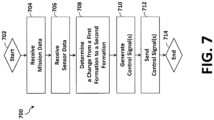
- a method of operating a plurality of aerial vehicles in an environment comprises: receiving, at a first command module of a first aerial vehicle navigating along a first flight path, sensor data from one or more sensors on board the first aerial vehicle, wherein the sensor data reflects one or more characteristics of the environment; determining, via the first command module, a change from a predetermined formation to a different formation for a second aerial vehicle based at least in part on the sensor data, wherein the predetermined formation and the different formation are relative to the first aerial vehicle; generating, via the first command module, control signals reflecting the change from the predetermined formation to the different formation; and sending the control signals from the first aerial vehicle to the second aerial vehicle.
- the method further comprises the step of: determining, via the first command module or a mission manager, a second flight path for a second aerial vehicle reflecting the change from the predetermined formation to the different formation, wherein the control signals reflect the second flight path for the second aerial vehicle.
- the method further comprises the steps of: receiving, at the first command module, feedback from the second aerial vehicle; and determining, via the first command module, an updated flight path for the second aerial vehicle, for changing to the different formation, based at least in part on the feedback.
- the method further comprises the step of: maneuvering, via a second command module of the second aerial vehicle, the second aerial vehicle to navigate along the second flight path.
- control signals comprise a first flight command to divert the second aerial vehicle from a flight path associated with the predetermined formation and to follow the second flight path
- the method further comprising the steps of: maneuvering, via the second command module of the second aerial vehicle, the second aerial vehicle to navigate along the second flight path; and receiving, via the second command module and from the first command module, a second flight command to return the second aerial vehicle from the second flight path to the flight path associated with the predetermined formation.
- the method further comprises the steps of: receiving, via the second command module, an alert signal; initiating, via the second command module, a dispersion pattern flight path, wherein the dispersion pattern flight path is different than the second flight path; maneuvering, via the second command module of the second aerial vehicle, the second aerial vehicle to navigate along the dispersion pattern flight path; and receiving, via the second command module, a termination alert, wherein the termination alert causes the second command module to instruct the second aerial vehicle to return to the second flight path.
- the method further comprises the steps of: receiving, via the second command module and from the first command module, zone data that indicates one or more zones proximate the second flight path; and maneuvering, via the second command module, the second aerial vehicle to enter the one or more zones based at least in part on the zone data, wherein the zone data includes a time component for the one or more zones, wherein the time component is a validity period or expiration time of the one or more zones.
- the different formation is a second predetermined formation relative to the first aerial vehicle that is different from the predetermined formation.
- the method further comprises the steps of: receiving, from the first command module and by a second command module of the second aerial vehicle, the control signals; generating, based on the control signals, a second flight path for the second aerial vehicle reflecting the change from the predetermined formation to the different formation; and maneuvering, via the second command module, the second aerial vehicle to navigate along the second flight path.
- the method further comprises the steps of: tracking, via a second command module of the second aerial vehicle, a position of the first aerial vehicle to yield a tracked position; and maneuvering, via the second command module, the second aerial vehicle to follow the first aerial vehicle based on the control signals and the tracked position of the first aerial vehicle.
- the method further comprises the step of receiving, at the first command module, additional sensor data from one or more additional sensors on board the second aerial vehicle that is different from the one or more sensors.
- the sensor data comprises one or more of weather data, location data, obstacle data, mapping data, payload data, formation data, and landing data.
- the change from the predetermined formation to the different formation comprises a first change
- the method further comprising the steps of: determining, via the first command module, a second change from the predetermined formation to the different formation for a third aerial vehicle based at least in part on the sensor data, wherein the second change is different than the first change; generating, via the first command module, second control signals reflecting the second change from the predetermined formation to the different formation; and sending the second control signals from the first aerial vehicle to the third aerial vehicle.
- control signals are configured to enable autonomous control of the second aerial vehicle and the third aerial vehicle to maintain the different formation, wherein the different formation is a predetermined aerial formation relative to the first aerial vehicle.
- the sensor data comprises data from a second set of sensors, on board the second aerial vehicle, different than the one or more sensors.
- the autonomous aerial vehicle navigation system further comprises: a mission manager, wherein the first command module or the mission manager is configured to determine a second flight path for the second aerial vehicle reflecting the change from the predetermined formation to the different formation, wherein the control signals reflect the second flight path for the second aerial vehicle.
- one or more of the first command module or mission manager is further configured to: receive feedback from the second aerial vehicle; and determine an updated flight path for the second aerial vehicle, for changing to the different formation, based at least in part on the feedback.
- the autonomous aerial vehicle navigation system further comprises: a second command module disposed on board the second aerial vehicle, wherein the second command module is configured to: maneuver the second aerial vehicle to navigate along the second flight path.
- the control signals comprise a first flight command to divert the second aerial vehicle from a flight path associated with the predetermined formation and to follow the second flight path, and wherein the autonomous aerial vehicle navigation system (100) further comprises a second command module second command module configured to: maneuver the second aerial vehicle to navigate along the second flight path; and receive, from the first command module, a second flight command to return the second aerial vehicle from the second flight path to the flight path associated with the predetermined formation.
- the second command module is further configured to: receive an alert signal; initiate a dispersion pattern flight path, wherein the dispersion pattern flight path is different than the second flight path; maneuver the second aerial vehicle to navigate along the dispersion pattern flight path; and receive a termination alert, wherein the termination alert causes the second command module to instruct the second aerial vehicle to return to the second flight path.
- the second command module is further configured to: receive, from the first command module, zone data that indicates one or more zones proximate the second flight path; and maneuver the second aerial vehicle to enter the one or more zones based at least in part on the zone data, wherein the zone data includes a time component for the one or more zones, wherein the time component is a validity period or expiration time of the one or more zones.
- the autonomous aerial vehicle navigation system is further configured to: receive, from the first command module, the control signals; generate based on the control signals, a second flight path for the second aerial vehicle reflecting the change from the predetermined formation to the different formation; and maneuver the second aerial vehicle to navigate along the second flight path.
- the second command module is further configured to: track a position of the first aerial vehicle to yield a tracked position; and maneuver the second aerial vehicle to follow the first aerial vehicle based on the control signals and the tracked position of the first aerial vehicle.
- the sensor data comprises one or more of weather data, location data, obstacle data, mapping data, payload data, formation data, and landing data.
- the change from the predetermined formation to the different formation comprises a first change
- the first command module is further configured to: determine a second change from the predetermined formation to the different formation for a third aerial vehicle based at least in part on the sensor data, wherein the second change is different than the first change; generate second control signals reflecting the second change from the predetermined formation to the different formation; and send the second control signals from the first aerial vehicle to the third aerial vehicle.
- control signals are configured to enable autonomous control of the second aerial vehicle and the third aerial vehicle to maintain the different formation, wherein the different formation is a predetermined aerial formation relative to the first aerial vehicle.
- the sensor data comprises first sensor data, wherein the one or more sensors on board the first aerial vehicle comprises a first set of sensors, the system further comprising: a second set of sensors on board the second aerial vehicle, wherein the second set of sensors are different than the first set of sensors, wherein the second command module is further configured to: receive second sensor data from the second set of sensors, wherein the second sensor data reflects one or more characteristics of the environment, and wherein the second change is based on the first sensor data and the second sensor data.
- the one or more sensors comprises an optical sensor and a non-optical sensor, where the sensor data is generated as a function of data from each of the optical sensor and the non-optical sensor.
- the one or more sensors includes a forward-facing optical sensor and a rear-facing optical sensor.
- a communication system for use in operating a plurality of aerial vehicles in an environment comprises: a first command module configured to: determine a change from a predetermined formation to a different formation for a second aerial vehicle based at least in part on sensor data, wherein the predetermined formation and the different formation are relative to a first aerial vehicle, generate control signals reflecting the change from the predetermined formation to the different formation, and send the control signals from the first aerial vehicle to a second command module of the second aerial vehicle; and the second command module, wherein the second command module is configured to: receive the control signals, and maneuver the second aerial vehicle to navigate along a flight path.
- the communication system further comprises a mission manager, wherein the first command module is configured to send the control signals to the second command module via the mission manager.
- one or more of the first command module, the second command module, or the mission manager is configured to: generate, based on the control signals, the flight path for the second aerial vehicle reflecting the change from the predetermined formation to the different formation.
- one or more of the first command module or the mission manager is further configured to: receive feedback from the second command module; and determine an updated flight path for the second aerial vehicle, for changing to the different formation, based at least in part on the feedback.
- control signals comprise one or more of: a flight command to divert the second aerial vehicle from the flight path and follow an modified flight path, an alert signal to initiate a dispersion pattern flight path, a termination alert to instruct the second aerial vehicle to return to the flight path, or zone data that indicates one or more zones proximate the flight path that can be used for navigation, wherein the second command module is further configured to: maneuver the second aerial vehicle to navigate based on the flight command, alert signal, termination alert, or zone data.
- the change from the predetermined formation to the different formation comprises a first change
- the system further comprising: a third command module, wherein the first command module is further configured to: determine a second change from the predetermined formation to the different formation for a third aerial vehicle based at least in part on the sensor data, wherein the second change is different than the first change; generate second control signals reflecting the second change from the predetermined formation to the different formation; and send the second control signals from the first aerial vehicle to the third command module, and wherein the third command module is configured to: receive the second control signals, and maneuver the third aerial vehicle to navigate based on the control signals.
- control signals are configured to enable autonomous control of the second aerial vehicle and the third aerial vehicle to maintain the different formation, wherein the different formation is a predetermined aerial formation relative to the first aerial vehicle.
- VTOL vertical takeoff and landing
- VTOL aircraft may include fixed-wing aircraft, rotorcraft (e.g., helicopters, multirotor, etc.), and/or tilt-rotor/tilt-wing aircraft.
- the term "and/or” means any one or more of the items in the list joined by “and/or”.
- "x and/or y” means any element of the three-element set ⁇ (x), (y), (x, y) ⁇ . In other words, “x and/or y” means “one or both of x and y”.
- "x, y, and/or z” means any element of the seven-element set ⁇ (x), (y), (z), (x, y), (x, z), (y, z), (x, y, z) ⁇ . In other words, "x, y, and/or z” means “one or more of x, y, and z.”
- circuits and “circuitry” refer to physical electronic components (e.g., hardware) and any software and/or firmware ("code") which may configure the hardware, be executed by the hardware, and or otherwise be associated with the hardware.
- code software and/or firmware
- a particular processor and memory may comprise a first "circuit” when executing a first set of one or more lines of code and may comprise a second "circuit” when executing a second set of one or more lines of code.
- circuitry is "operable" to perform a function whenever the circuitry comprises the necessary hardware and code (if any is necessary) to perform the function, regardless of whether performance of the function is disabled, or not enabled (e.g., by a user-configurable setting, factory trim, etc.).
- the terms "communicate” and “communicating” as used herein, include both conveying data from a source to a destination and delivering data to a communications medium, system, channel, network, device, wire, cable, fiber, circuit, and/or link to be conveyed to a destination.
- the term “communication” as used herein means data so conveyed or delivered.
- the term “communications” as used herein includes one or more of a communications media, system, channel, network, device, wire, cable, fiber, circuit, and/or link.
- the terms “exemplary” and “example” mean “serving as an example, instance or illustration.”
- the embodiments described herein are not limiting, but rather are exemplary only. It should be understood that the described embodiments are not necessarily to be construed as preferred or advantageous over other embodiments.
- the terms “embodiments of the disclosure”, “embodiments,” or “disclosure” do not require that all embodiments of the disclosure include the discussed feature, advantage or mode of operation.
- Coupled means a relationship between or among two or more devices, apparatuses, files, circuits, elements, functions, operations, processes, programs, media, components, networks, systems, subsystems, and/or means, constituting any one or more of: (i) a connection, whether direct or through one or more other devices, apparatuses, files, circuits, elements, functions, operations, processes, programs, media, components, networks, systems, subsystems, or means; (ii) a communications relationship, whether direct or through one or more other devices, apparatuses, files, circuits, elements, functions, operations, processes, programs, media, components, networks, systems, subsystems, or means; and/or (iii) a functional relationship in which the operation of any one or more devices, apparatuses, files, circuits, elements, functions, operations, processes, programs, media, components, networks, systems, subsystems, or means depends, in whole or in part, on the operation
- data means any indicia, signals, marks, symbols, domains, symbol sets, representations, and any other physical form or forms representing information, whether permanent or temporary, whether visible, audible, acoustic, electric, magnetic, electromagnetic, or otherwise manifested.
- data is used to represent predetermined information in one physical form, encompassing any and all representations of corresponding information in a different physical form or forms.
- database means an organized body of related data, regardless of the manner in which the data or the organized body thereof is represented.
- the organized body of related data may be in the form of one or more of a table, a map, a grid, a packet, a datagram, a frame, a file, an e-mail, a message, a document, a report, a list, or data presented in any other form.
- the term "memory device” means computer hardware or circuitry to store information for use by a processor.
- the memory device can be any suitable type of computer memory or any other type of electronic storage medium, such as, for example, read-only memory (ROM), random access memory (RAM), cache memory, compact disc read-only memory (CDROM), electro-optical memory, magneto-optical memory, programmable read-only memory (PROM), erasable programmable read-only memory (EPROM), electrically-erasable programmable read-only memory (EEPROM), a computer-readable medium, or the like.
- ROM read-only memory
- RAM random access memory
- CDROM compact disc read-only memory
- EPROM erasable programmable read-only memory
- EEPROM electrically-erasable programmable read-only memory
- network includes both networks and inter-networks of all kinds, including the Internet, and is not limited to any particular network or inter-network.
- processor means processing devices, apparatuses, programs, circuits, components, systems, and subsystems, whether implemented in hardware, tangibly embodied software, or both, and whether or not it is programmable.
- processor includes, but is not limited to, one or more computing devices, hardwired circuits, signal-modifying devices and systems, devices and machines for controlling systems, central processing units, programmable devices and systems, field-programmable gate arrays, application-specific integrated circuits, systems on a chip, systems comprising discrete elements and/or circuits, state machines, virtual machines, data processors, processing facilities, and combinations of any of the foregoing.
- the processor may be, for example, any type of general purpose microprocessor or microcontroller, a digital signal processing (DSP) processor, an application-specific integrated circuit (ASIC).
- DSP digital signal processing
- ASIC application-specific integrated circuit
- the processor may be coupled to, or integrated with, a memory device.
- an aerial vehicle e.g., an unmanned, optionally-manned, or manned vehicle
- flight operations e.g., an unmanned, optionally-manned, or manned vehicle
- the following description will be in reference to one or more flight operations.
- the systems, methods, and examples discussed herein may be used for surveillance and package delivery operations to a residence, business, or in another civilian context. In other examples, the described systems, methods, and examples may be used for a different operation.
- each aerial vehicle of the plurality of aerial vehicles may be equipped with sophisticated sensor systems, processing systems, and communication systems to enable the plurality of aerial vehicles to operate as a unit.
- each aerial vehicle may sense environmental conditions and determine or adjust a flight path based on the sensed conditions.
- one or more aerial vehicles of the plurality of aerial vehicles may sense different environmental conditions, resulting in differing or nonsynchronous flight paths of the plurality of aerial vehicles.
- Such nonsynchronous flight paths may make the mission less efficient, more complicated, and even more dangerous than a plurality of aerial vehicles operating as a substantially synchronized unit.
- the autonomous aerial vehicle navigation system of the present disclosure may include one or more aerial vehicles of a plurality of aerial vehicles configured to communicate with one or more other aerial vehicles of the plurality of aerial vehicles to determine or update flight paths, provide command signals, control the aerial vehicles, identify hazards or environmental conditions, or otherwise provide information relevant to the aerial operation.
- one or more of the aerial vehicles of the plurality of aerial vehicles may exhibit different functionalities, sensing capabilities, computing capabilities, or other differences than another aerial vehicle of the plurality of aerial vehicles and may receive such information from the more sophisticated aerial vehicle.
- At least one aerial vehicle of the plurality of aerial vehicles may sense or learn information reflecting one or more characteristics of the environment and share such information with one or more other aerial vehicles of the plurality of aerial vehicles, enabling the shared information to be used to control operation of plurality of aerial vehicles.
- the fleet or pack of the plurality of aerial vehicles may be less expensive, more efficient, more robust, easier to operate, more synchronous, and/or safer than a single aerial vehicle or a plurality of aerial vehicles not operated by the autonomous aerial vehicle navigation system described herein.
- Figure 1a illustrates a schematic diagram of an example autonomous aerial vehicle navigation system (AAVNS) 100 including a plurality of aerial vehicles 102 operating in an environment 118.
- the plurality of aerial vehicles 102 includes two or more aerial vehicles (illustrated as three aerial vehicles - first, second, and third aerial vehicles 102a, 102b,102c).
- Figure 1a will be described with respect to a first aerial vehicle 102a, a second aerial vehicle 102b, and a third aerial vehicle 102c
- the plurality of aerial vehicles 102 may include any suitable number of aerial vehicles, such as, for example, two aerial vehicles, three aerial vehicles, six aerial vehicles, ten aerial vehicles, or twelve or more aerial vehicles, for conducting a operation.
- aerial vehicles 102 depicted in Figure 1a are aerial vehicles
- the autonomous vehicles described herein may include any vehicle, device, component, element, etc., that may be usefully navigated using the principles of the system disclosed herein, including, without limitation, any unmanned vehicle, optionally-manned vehicle, manned vehicle, aircraft, ground vehicle, aquatic vehicle, space vehicle, remote-controlled vehicle, large vehicle, small vehicle, etc., unless explicitly stated otherwise or made clear from the text.
- an AAVNS 100 including a plurality of aerial vehicles 102 is configured to complete one or more missions.
- AAVNS 100 can be configured to complete one or more operations including humanitarian relief operations, rescue operations, cargo delivery, or a combination thereof.
- second and third aerial vehicles 102b, 102c are carrying a payload 116 to be delivered to a landing zone 112.
- payload 116 may include supplies to be delivered to a company, platoon, or squad.
- payload 116 may include food, medication, medical equipment, or the like for delivery of humanitarian relief.
- payload 116 may include any suitable payload, including other vehicles (whether aerial or ground-based vehicles).
- the plurality of aerial vehicles 102 is configured to complete one or more delivery operations
- payload 116 may include a package for delivery to a residence or business. While the payload 116 of Figure 1a is illustrated as a suspended cargo, one of skill in the art would recognize that other arrangements are possible and the disclosure should not be construed as limited to a particular configuration.
- the payload 116 may be coupled directly to (or positioned within) one or more of the aerial vehicles 102a, 102b, 102c. In certain aspects, the payload 116 may be omitted from one or more of the aerial vehicles 102a, 102b, 102c.
- the AAVNS 100 is configured to operate plurality of aerial vehicles 102.
- AAVNS 100 may be configured to operate plurality of aerial vehicles 102 in one or more predetermined formations 126 and to adjust dynamically a predetermined formation 126.
- AAVNS 100 may also be capable of generating, for each of the plurality of aerial vehicles 102, complete flight paths 104a, 104b, 104c from launch to landing (or touchdown), executing new flight paths 104a-104c as dictated by mission plan data, sensor data, or the like. In this way, AAVNS 100 detects and instructs the plurality of aerial vehicles 102 to avoid obstacles in flight, as well as in a descent-to-land phase of the flight, in a potentially GPS-denied environment.
- AAVNS 100 may operate one or more of plurality of aerial vehicles 102 to autonomously identify and execute an aircraft landing at a landing zone 112 to complete a mission.
- AAVNS 100 may be further configured to perceive physical features of the ground to negotiate any conditions that could prevent a safe approach and/or landing of one or more of aerial vehicles 102a through 102c (e.g., unsafe/unstable ground composition, marshy/muddy ground, vegetation, and/or water) and may also be able to negotiate sloped landing sites.
- AAVNS 100 operates the plurality of aerial vehicles 102 based on sensor data generated by one or more sensors, which can be positioned on one or more of plurality of aerial vehicles 102 or even ground-based objects 130 (e.g., stationary or mobile units).
- each aerial vehicle 102a through 102c may include one or more sensors (e.g., sensors 108a, 108b, 108c) and one or more ground-based objects 130 may include sensors 108d.
- sensors 108a, 108b, 108c, 108d are configured to generate sensor data reflecting one or more characteristics of environment 118, such as, weather data, location data, obstacle data, mapping data, payload data, formation data, landing data, or the like.
- AAVNS 100 can use the sensor data to determine an alteration of a predetermined formation 126a (e.g., a first predetermined formation) to a different formation 126c (e.g ., a second predetermined formation) of plurality of aerial vehicles 102, generate a flight path, execute a new flight path, detect obstacles, avoid obstacles, configure landing, or the like for one or more aerial vehicles 102a through 102c.
- the different formation 126c is a second predetermined formation relative to the first aerial vehicle 102a that is different from the predetermined formation 126a.
- Example predetermined formations are discussed in greater detail below with reference to Figures 3a-3f .
- the second predetermined formation (i.e., different formation 126c) is a straight-line formation, triangular formation, leader-subleader-follower formation, circular formation, disperse formation, or a complex formations that include one or more combinations of formations.
- the one or more sensors 108a, 108b, 108c, 108d may either each employ the same type of sensor or employ a combination of different types sensors, in either case, the collective sensor data from the one or more sensors 108a, 108b, 108c, 108d can be used for dynamic (e.g ., real-time or near real time) calculations (e.g ., recalculating trajectories during operation). Therefore, it is not required to change the formation from one predetermined formation to another, but rather the AAVNS 100 can alter the predetermined formation dynamically as a function of the sensor data.
- dynamic e.g ., real-time or near real time
- the AAVNS 100 is configured to operate the plurality of aerial vehicles 102 in one or more predetermined formations 126 and to transition the plurality of aerial vehicles 102 between predetermined formations 126 ( e.g ., based on sensor data and/or commands from the first aerial vehicle 102a, the mission manager 114, etc.).
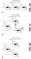
- Figure 1b illustrates a top plan view of the plurality of aerial vehicles 102 operating in an example predetermined formation 126a ( e.g ., the triangular arrangement of Figure 1a ).
- the AAVNS 100 can transition the plurality of aerial vehicles 102 from the predetermined formation 126a to a different formation 126c, which will, for simplicity of illustration, be described as a linear formation. To that end, as illustrated in transition formation 126b of Figure 1c , the AAVNS 100 instructs the third aerial vehicle 102b to transition laterally and rearwardly (as indicated by arrow A, e.g.
- Figure 1d illustrates the plurality of aerial vehicles 102 operating in the different formation 126c upon completion of the transition. While triangular and linear formations are illustrated in this example, other formations are contemplated as will described in connection with Figures 3a through 3f .
- AAVNS 100 includes unmanned or optionally manned aerial vehicles 102a through 102c.
- aerial vehicles 102a through 102c include unmanned vehicles
- aerial vehicles 102a through 102c may be configured to operate in meteorological or operating conditions that may limit traditional manned cargo delivery, especially in austere terrains with low visibility due to dust, precipitation, or fog. In this way, the use of unmanned aerial vehicles 102a through 102c may allow completion missions too dangerous or difficult for the use of traditional manned vehicles.
- Aerial vehicles 102a through 102c may include any type of unmanned or optionally manned aerial vehicles. As shown in Figures 1a through 1d , aerial vehicles 102a through 102c may be helicopters. As another example, aerial vehicles 102a through 102c may include multirotor aerial vehicle, such as a quadcopter, or aerial vehicles with forward flight capability, such as fixed-wing aircraft. In other examples, aerial vehicles 102a through 102c may include another suitable unmanned or optionally manned aerial vehicles. In still another example, one or more or plurality of aerial vehicles 102 may be manned. In some examples, aerial vehicles 102a through 102c may all be the same type of unmanned or optionally-manned aerial vehicle. In other examples, one or more of aerial vehicles 102a through 102c may be different from one or more other aerial vehicles of plurality of aerial vehicles 102.
- suitable aerial vehicles 102a through 102c may be configured to operate at low density, high altitudes (greater than 12,000 feet density altitude). Aerial vehicles 102a through 102c may be further configured to carry small or large payload internally. Aerial vehicles 102a through 102c may travel at, for example, low or high speed.
- one or more aerial vehicles 102a through 102c may be configured to descend and land within a window/timeframe and to execute an autonomous landing as close to landing zone 112 as possible (e.g ., an objective of less than 1 meter error from a computer-designated landing zone 112 center point) without over-flight of landing zone 112 ( e.g ., the vehicle executes a straight-in approach without a first pass).
- an autonomous landing as close to landing zone 112 as possible (e.g ., an objective of less than 1 meter error from a computer-designated landing zone 112 center point) without over-flight of landing zone 112 (e.g ., the vehicle executes a straight-in approach without a first pass).
- aerial vehicles 102a through 102c may be able to operate at night (thus facilitating operation 24 hours a day, 7 days a week) in possibly satellite-denied settings (e.g ., preventing communication and/or satellite-based geo-location such as that provided by the Global-Positioning System (“GPS”), denoted “GPS-denied”), and in all types of environments, including steep and rugged terrain, instrument meteorological conditions (IMC) and non-icing conditions, high and hot environments, and in dust and sand conditions with minimum visibility.
- GPS Global-Positioning System
- Aerial vehicles 102a through 102c may be configured to operate in weather conditions that exceed those of manned flight capabilities.
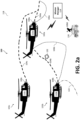
- FIG. 2a is an enlarged view of the example AAVNS 100 including plurality of aerial vehicles 102 in environment 118.
- AAVNS 100 is configured to operate each aerial vehicle 102a through 102c of plurality of aerial vehicles 102 to substantially follow a respective flight path 104a, 104b, 104c.
- first aerial vehicle 102a may be operated to navigate along first flight path 104a
- second aerial vehicle 102b may be operated to navigate along second flight path 104b
- third aerial vehicle 102c may be operated to navigate along third flight path 104c.
- flight paths 104a, 104b, 104c may correspond to a predetermined formation of plurality of aerial vehicles 102.
- a first command module 110a of first aerial vehicle 102a receives a mission request or mission data, such as from a user device, a mission manager 114, or the like.
- First aerial vehicle 102a is configured to determine a first flight path 104a based on the mission request or mission data.
- first command module 110a may execute a flight path to land the plurality of aerial vehicles 102 at the landing zone 112 (as shown in Figure 1a ) in order for plurality of aerial vehicles 102 to complete the received mission.
- Such flight paths may include waypoints along the flight paths to meet the mission objective.
- first command module 110a may determine a predetermined formation 126a of first aerial vehicle 102a relative to one or more aerial vehicles of plurality of aerial vehicles 102 based on the mission request of mission data. First command module 110a is configured to further determine a set of routes as part of first flight path 104a and/or the predetermined formation 126a. In other examples, first command module 110a may determine a first flight path 104a in an additional or alternative manner. Additionally, or alternatively, a different device, such as mission manager 114, may determine first flight path 104a or predetermined formation and send said first flight path 104a or predetermined formation to first command module 110a for execution.
- a different device such as mission manager 114, may determine first flight path 104a or predetermined formation and send said first flight path 104a or predetermined formation to first command module 110a for execution.
- the mission manager 114 can set a predetermined formation for first flight path 104a that then affects flights paths second flight path 104b and third flight path 104c.
- first flight path 104a is a predetermined route
- the second flight path 104b and third flight path 104c under a formation flight, may be accomplished in one of multiple ways.
- the second flight path 104b and third flight path 104c can be preset based on first flight path 104a.
- the second flight path 104b and third flight path 104c can be determined based on the formation itself ( e.g ., maintaining absolute coordinates between the flight paths 104a, 104b, 104c).
- first command module 110a autonomously maneuvers first aerial vehicle 102a to follow, or substantially follow, first flight path 104a.
- first command module 110a may update first fight path 104a (e.g ., to avoid obstacles, save fuel, reduce flight time, etc.) or otherwise determine a first updated (or new) flight path 106a for first aerial vehicle 102a using sensor data reflecting one or more characteristics of environment 118 generated by a first sensor 108a (or another sensor in the AAVNS 100, including land-based sensors 108d). In such examples, first command module 110a may then maneuver first aerial vehicle 102a to navigate along the first updated flight path 106a.
- First command module 110a may autonomously maneuver first aerial vehicle 102a in any suitable manner.
- mission manager 114 or another component of AAVNS 100 are configured to autonomously maneuver first aerial vehicle 102a, such as by determining control signals based on sensed data and sending said control signals to first command module 110a.
- first command module 110a is configured to generate control signals as a function of the sensor data generated by first sensor 108a.
- first command module 110a can generate control signals including one or more flight commands based at least in part on the sensor data or a flight path, which is based at least in part on the sensor data. That is, first command module 110a may generate control signals to control the operation of other aerial vehicles, such as second aerial vehicle 102b.
- first command module 110a is configured to generate control signals that can be used by a second command module 110b of second aerial vehicle 102b to autonomously maneuver second aerial vehicle 102b.
- first command module 110a may determine a change from a predetermined formation 126a to a different formation 126c and may generate control signals reflecting the change.
- first command module 110a of first aerial vehicle 102a is configured to determine second flight path 104b for second aerial vehicle 102b based at least in part on the sensor data to reflect the change from the predetermined formation 126a to the different formation 126c.
- First command module 110a may then generate control signals reflecting the second flight path 104b.
- First command module 110a is configured to send the generated control signals to send to second command module 110b of second aerial vehicle 102b. In other examples, first command module 110a is configured to send the control signals to mission manager 114 in addition to, or as an alternative to, sending the control signals to second command module 110b.
- second command module 110b of second aerial vehicle 102b receives the control signals from first command module 110a. In other examples, second command module 110b receives the control signals from mission manager 114 or another component of AAVNS 100. Second command module 110b is configured to autonomously maneuver second aerial vehicle 102b based on the received control signals. For example, second command module 110b may autonomously maneuver second aerial vehicle 102b from its position in the predetermined formation 126a to its position in the different formation 126c. Second command module 110b may autonomously maneuver second aerial vehicle 102b using any suitable method.
- control signals may define a change from a predetermined formation 126a to a different formation 126c, which may be formations of one or more of plurality of aerial vehicles 102 as described above.
- plurality of aerial vehicles 102 may be in a straight-line formation, a triangular formation, a circular formation, a diamond formation, a disperse formation, an arrow formation, or any other formation at any distance apart from each other to support the mission objective.
- each aerial vehicle of plurality of aerial vehicles 102 may be at a position in the predetermined formation 126. In other examples, less than all of plurality of aerial vehicles 102 may in the predetermined formation 126.
- a plurality of aerial vehicles 102 may include a combination of different formation types to form a complex predetermined formation. For instance, some of plurality of aerial vehicles 102 may be in a straight-line formation while other aerial vehicles of plurality of aerial vehicles 102 may be in a disperse formation. Additional examples of predetermined formations of plurality of aerial vehicles 102 will be described with respect to Figures 3a through 3f .
- the predetermined formations can employ a hierarchical relationship among multiple levels of formations.
- control signals may define a second flight path 104b (or flight commands corresponding to second flight path 104b) that substantially mimics the first flight path 104a, which was followed by first aerial vehicle 102a.
- the second aerial vehicle 102b may follow in the same or substantially the same flight path as the first flight path 104a previously followed by the first aerial vehicle 102a.
- the control signals may define a second flight path 104b that targets and tracks the first aerial vehicle 102a itself, rather than merely following the first flight path 104a.
- control signals may define second flight path 104b, or flight commands corresponding to second flight path 104b, that do not substantially mimic first flight path 104a.
- first sensor 108a may generate sensor data that indicates the presence of an obstacle in the way of second flight path 104b when second aerial vehicle 102b is mimicking first flight path 104a.
- first sensor 108a may generate sensor data indicating an obstacle (e.g ., obstacle 132) that could harm or prevent delivery of payload 116.
- second aerial vehicle 102b may be able to substantially follow first flight path 104a without consequence, but payload 116 may be affected by the presence of the obstacle detected by first sensor 108a.
- first command module 110a may generate control signals as a function of the sensor data that results in second aerial vehicle 102b following second flight path 104b without harm or other consequences to second aerial vehicle 102b or payload 116. In other examples, first command module 110a may generate control signals based on factors in addition to, or as alternative to, the effect of the generated sensor data on second aerial vehicle 102b and/or payload 116.
- the first command module 110a can generate and send zone data to the second command module 110b to navigate (or assist in navigating) the second aerial vehicle 102b.
- the zone data may indicate one or more zones 120 within an airspace that have been deemed safe (e.g ., obstacle free) for flight or navigation by the second aerial vehicle 102b, for example.
- the first command module 110a can generate zone data using first sensor 108a as the first aerial vehicle 102a navigates along its first flight path 104a.
- the mission manager 114 tracks and monitors any obstacles in its sensor field of view 128.
- the first command module 110a may generate and communicate to another aerial vehicle (e.g ., the second aerial vehicle 102b) zone data.
- the second aerial vehicle 102b is illustrated as navigating along second flight path 104b that trails the first aerial vehicle 102a) zone data. If there are no materially relevant obstacles identified within the sensor field of view 128 (as illustrated in Figure 2b ), the zone data indicates that the zone 120 proximate the second flight path 104b is deemed safe ( e.g ., obstacle free) for flight or navigation by second aerial vehicle 102b. If one or more relevant obstacles are identified, the zone data may further indicate specifics of the obstacle(s) (e.g ., location, size, shape, trajectory, speed, heading, etc.).
- the path boundaries 124 along the first flight path 104a define the zone 120 for other aerial vehicles (e.g ., those trailing the first aerial vehicle 102a).
- the path boundaries 124 correspond to the size (e.g ., width, diameter, etc.) of the sensor field of view 128, which is generally dictated by the available sensor data (e.g ., the type, resolution, and penetration/depth of the first sensor 108a).
- the zone data may include a time component (e.g ., a validity period or expiration time).
- the zone data may indicate that the zone 120 is deemed safe for only a predetermine amount of time after a triggering event (e.g ., sensor reading, transmission of sensor data, etc.). That is, once the sensor payload 108a has navigated out of range of the zone 120, the determination whether or not obstacles exist in the zone 120 is deemed outdated after a predetermined period of time has elapsed from the triggering event.
- a triggering event e.g ., sensor reading, transmission of sensor data, etc.
- the zone data can also be communicated to the third aerial vehicle 102c, which is illustrated as navigating along third flight path 104c that trails the second aerial vehicle 102b.
- the zone data can be communicated directly to the third aerial vehicle 102c from the first aerial vehicle 102a, or via the second aerial vehicle 102b ( e.g ., as a relay).
- Second command module 110b may then be able to autonomously maneuver second aerial vehicle 102b to enter or operate within zones 120 based at least in part one the received zone data. In this way, second command module 110b may have more flexibility in autonomously maneuvering second aerial vehicle 102b rather than strictly relying on flight commands and/or flight paths received from first command module 110a or mission manager 114. Moreover, in some examples, the zone data may indicate zones 120 in which second aerial vehicle 102b can navigate to form a predetermined formation. In other examples, second command module 110b may not receive zone data and may autonomously maneuver second aerial vehicle 102b based on the control signals received from first command module 110a or mission manager 114.
- second command module 110b of second aerial vehicle 102b receives its original flight path (e.g ., second flight path 104b) from one of first aerial vehicle 102a and/or mission manager 114.
- second command module 110b may receive control signals, sensor data (from first command module 110a, mission manager 114, or second sensors 108b), flight commands, or the like and determine, based on the control signals, sensor data, or flight commands, a modified flight path (e.g ., second updated flight path 106b).
- Second command module 110b is configured to compare the original flight path to the modified flight path and determine any differences between the original flight path and modified flight path. In some such examples, if second command module 110b determines ( e.g ., detects or identifies) any differences, second command module 110b may autonomously maneuver second aerial vehicle 102b to follow the modified flight path.
- first command module 110a or mission manager 114 is configured to compare and modify flight paths.
- first command module 110a or mission manager 114 may send the modified flight paths (e.g ., as control signals) to second command module 110b to enable autonomous control of second aerial vehicle 102b based on the modified flight paths.
- first command module 110a is configured to send a control signal including a flight command to second command module 110b to divert second aerial vehicle 102b from an original flight path (e.g ., second flight path 104b) to follow a modified flight path (e.g ., second updated flight path 106b to avoid an obstacle 132).
- Second command module 110b may receive the control signal with the flight command instructing second aerial vehicle 102b to follow modified flight path and may autonomously maneuver second aerial vehicle 102b to move substantially along the modified flight path.
- second command module 110b may receive control signals including a second flight command from first command module 110a to return second aerial vehicle 102b from modified flight path back to the original flight path ( e.g., once clear of the obstacle 132). Second command module 110b may then autonomously maneuver second aerial vehicle 102b to navigate along second flight path 104b.
- second aerial vehicle 102b may include one or more sensors 108b configured to track the location and/or position of first aerial vehicle 102a.
- second set of sensors 108b is configured to generate sensor data reflecting the location of, position of, distance to, or the like of first aerial vehicle 102a.
- Second command module 110b may then be configured to generate control signals, flight commands, and/or flight paths as a function of the sensor data such that second aerial vehicle 102b is autonomously maneuvered to follow first aerial vehicle 102a.
- second sensors 108b may be less advanced than first set of sensors 108a, as second sensors 108b may only track the position of first aerial vehicle 102a without generating sensor data reflecting characteristics of environment 118.
- second sensors 108b is configured to generate sensor data reflective of both the position of first aerial vehicle 102a and characteristics of environment 118.
- one command module may maneuver the another aerial vehicle to autonomously follow the aerial vehicle based on the control signals and a tracked position of the aerial vehicle.
- first aerial vehicle 102a is configured to track the position of second aerial vehicle 102b.
- First command module 110a of first aerial vehicle 102a may then generate control signals including flight commands, a flight path, or a predetermined formation to send to second command module 110b such that second command module 110b can autonomously maneuver second aerial vehicle 102b based on the received control signals.
- second aerial vehicle 102b may include fewer, varied (e.g ., sensors with different functionalities, sensing capabilities, computing capabilities, or the like), or even no sensors 108b and may receive control signals from first aerial vehicle 102a without second command module 110b having to analyze sensor data and generate control signals on its own.
- various sensors may be distributed among the multi-vehicle formation to collectively provide a more robust (e.g ., more validated) situational awareness to one or more aerial vehicles in the formation.
- second command module 110b may receive an alert signal, such as from first command module 110a or mission manager 114. Upon receipt of the alert signal, second command module 110b may initiate a dispersion pattern flight path 122, which is illustrate as being different than second flight path 104b. Therefore, upon receipt of the alert signal, second command module 110b can autonomously maneuver second aerial vehicle 102b to follow dispersion pattern flight path 122 and avoid a detected obstacle, danger, hazard, or the like that may have prompted first command module 110a or mission manager 114 to send the alert signal.
- first command module 110a or mission manager 114 is configured to send a termination alert to second command module 110b upon determining that the event prompting the alert signal is no longer present or active. Second command module 110b, upon receiving the termination alert, may instruct or maneuver second aerial vehicle 102b to return to navigating along second flight path 104b.
- first aerial vehicle 102a and/or second aerial vehicle 102b is configured to generate and send control signals to third command module 110c of third aerial vehicle 102c for third command module 110c to autonomously maneuver third aerial vehicle 102c based on the control signals.
- first command module 110a of first aerial vehicle 102a may generate control signals including a change from one predetermined formation to another, flight commands, or third flight path 104c in the same or a similar manner to that as described above with respect to second aerial vehicle 102b.
- first command module 110a may determine a second change from the predetermined formation 126a to the different formation 126c for third aerial vehicle 102c based on the sensor data.
- First command module 110a may then generate the control signals to reflect the second change from its position in the predetermined formation 126a to its position in the different formation 126c.
- third command module 110c of third aerial vehicle 102c may autonomously maneuver third aerial vehicle 102c based on the control signals.
- first command module 110a of first aerial vehicle 102a is configured to send control signals to both second aerial vehicle 102b and third aerial vehicle 102c such that second and third aerial vehicles 102b, 102c maintain a predetermined aerial formation relative to first aerial vehicle 102a.
- second command module 110b of second aerial vehicle 102b is configured to generate control signals including flight commands or third flight path 104c and send such control signals to third command module 110c.
- third aerial vehicle 102c is configured to track and follow at least one of first aerial vehicle 102a or second aerial vehicle 102b.
- plurality of aerial vehicles 102 may include more than three aerial vehicles in some examples.
- the additional aerial vehicles is configured to receive control signals from another aerial vehicle of plurality of aerial vehicles 102 or from mission manager 114 in accordance with the present disclosure. Therefore, AAVNS 100 enables one or more aerial vehicles of plurality of aerial vehicles 102 to have simpler capability than one or more other aerial vehicles of plurality of aerial vehicles 102 while maintaining safe, efficient, accurate, and effective operation and mission completion.
- AAVNS 100 may also be a safe, efficient, accurate, and effective manner of operating plurality of aerial vehicles 102 in one or more predetermined formations.
- One or more of plurality of aerial vehicles 102 includes sensors (e.g., sensors 108a, 108b, 108c) configured to generate sensor data including weather data, location data, obstacle data, mapping data, payload data, formation data, landing data, or the like.
- Weather data may include information such as air data, storm data, temperature data, visibility data, or any other weather data.
- Location data may include information such as the location of one or more aerial vehicles of plurality of aerial vehicles 102, an operating base, a fuel zone, a combat outpost, or any other location data.
- Obstacle data may include information such as the location of static obstacles (e.g ., towers, trees, building, etc.) or dynamic obstacles (e.g ., no fly zones due to enemy activity, other vehicles, etc.), identification of the obstacle, hazard detection information, or any other obstacle data.
- Mapping data may include information to place detected obstacles or hazards, weather systems, landing zones, or the like relative to each other.
- Payload may include information pertaining to payload 116 optionally carried by one or more aerial vehicles 102a through 102c, such as, for example, the weight of payload 116, the status of payload 116, the location of payload 116, or the like.
- Formation data may include data regarding a formation of plurality of aerial vehicles 102.
- sensors may be able to determine the formation of aerial vehicles 102a through 102c relative to one other (e.g ., in a straight-line formation, in a triangular formation, etc.).
- Landing data may include data about the landing zone, such as, for example, the terrain of the landing zone, gesture detection information, the grade of the landing zone, or any other landing data.
- sensor data is described herein to include weather data, location data, obstacle data, mapping data, payload data, formation data, and/or landing data
- sensor data may include any additional or alternative sensor data applicable to AAVNS 100.
- AAVNS 100 may in turn use said generated sensor data to generate control signals for one or more of plurality of aerial vehicles 102.
- Sensors may include any suitable sensors, such as one or more of light detection and ranging (LIDAR), Radio Detection and Ranging (RADAR), electro optical infrared (EO/IR) Imagers, a stereo vision camera system, radio altimeter (RADALT), air data sensor, GPS/inertial navigation system (INS), or any other suitable sensor.
- LIDAR light detection and ranging
- RADAR Radio Detection and Ranging
- EO/IR electro optical infrared
- RADALT radio altimeter
- INS GPS/inertial navigation system
- one or more of aerial vehicles 102a through 102c may include a single sensor 108.
- one or more of aerial vehicles 102a through 102c may include two or more sensors 108, which may be the same or different.
- the one or more of sensors may include optical sensors and non-optical sensor (e.g ., RADAR, acoustic sensors, RADALT, air data sensor, microelectromechanical systems (MEMS), etc.).
- one or more of plurality of aerial vehicles 102 may not include any sensors 108.
- first aerial vehicle 102a may include one or more sensors 108a and second and/or third aerial vehicles 102b, 102c may not include sensors 108b, 108c.
- first aerial vehicle 102a may include one or more sensors 108a that are more sophisticated (e.g ., more accurate, enhanced detection capabilities, more granular sensing, etc.) than sensors 108b, 108c of second and/or third aerial vehicles 102b, 102c.
- One or more of sensors may be pointed to certain directions with regard to the flight direction, for example forward facing, rear-facing, downward-facing, or omni-directional.
- one or more sensors 108a of first aerial vehicle 102a may include a forward-facing optical sensor and a rear-facing optical sensor.
- at least one of the forward-facing optical sensor or the rear-facing optical sensor may include a LIDAR sensor.
- one or both of the forward-facing or rear-facing sensor may include a sensor other than a LIDAR or optical sensor.
- each aerial vehicle 102a through 102c may include one or more sensors 108a, 108b, 108c configured to generate sensor data.
- one of first aerial vehicle 102a, second aerial vehicle 102b, or third aerial vehicle 102c may have fewer or different ( e.g ., different functionalities, sensing capabilities, computing capabilities, etc.) sensors than another of first aerial vehicle 102a, second aerial vehicle 102b, or third aerial vehicle 102c.
- second aerial vehicle 102b may include second sensors 108b that are different than first sensors 108a of first aerial vehicle 102a. Additionally, or alternatively, second sensors 108b may include a fewer number of sensors than first sensors 108a. In this way, first sensors 108a of first aerial vehicle 102a may be configured to generate enhanced sensor data (e.g ., more sensor data, more granular sensor data, more accurate sensor data, etc.) than second sensors 108b of second aerial vehicle 102b.
- enhanced sensor data e.g ., more sensor data, more granular sensor data, more accurate sensor data, etc.
- second aerial vehicle 102b may not include any sensors configured to generate sensor data that reflects one or more characteristics of environment 118, and second aerial vehicle 102b may instead obtain relevant flight information (e.g ., in the form of control signals) from first command module 110a or mission manager 114.
- first sensors 108a on board first aerial vehicle 102a may face in a different direction or include different types of sensors than one or more other aerial vehicles of plurality of aerial vehicles 102.
- the AAVNS 100 may fuse the sensor data from the various aerial and ground-based sensors (e.g ., one or more sensors 108a, 108b, 108c, 108d) to provide increased perception of the environment 118 via, for example, the mission manager 114 and/or one or more of the first, second, or third command modules 110a, 110b, 110c.
- various aerial and ground-based sensors e.g ., one or more sensors 108a, 108b, 108c, 108d
- the second aerial vehicle 102b may employ different, less sophisticated, or fewer sensors configured to generate sensor data reflecting one or more characteristics of environment 118.
- the second aerial vehicle 102b may entirely omit such sensors and rely solely on sensor date from the first aerial vehicle 102a (or another source). Therefore, the second aerial vehicle 102b may be less expensive to manufacture, operate, or maintain compared to, for example, the first aerial vehicle 102a, while still enabling second aerial vehicle 102b to obtain relevant characteristics of environment 118 (from first command module 110a of first aerial vehicle 102a or mission manager 114).
- AAVNS 100 including second aerial vehicle 102b being less expensive than first aerial vehicle 102a may enable AAVNS 100 to be less expensive overall than some other autonomous vehicle control systems, while enabling AAVNS 100 to efficiently and safely complete missions.
- third aerial vehicle 102c may have different sensors than those of either or both of first aerial vehicle 102a or second aerial vehicle 102b and receive control signals generated as a function of sensor data from one or both of first command module 110a, second command module 110b, or mission manager 114.
- any aerial vehicle 102a through 102c of plurality of aerial vehicles 102 may have less sensing coverage than any other aerial vehicle 102a through 102c of plurality of aerial vehicles 102.
- plurality of aerial vehicles 102 may include ten aerial vehicles.
- a first aerial vehicle such as first aerial vehicle 102a, may be the most sophisticated aerial vehicle, or leader of plurality of aerial vehicles 102.
- That plurality of aerial vehicles 102 may further include three aerial vehicles, or subleaders, that are different from those of the first aerial vehicle, or leader, but are more sophisticated than the remaining six aerial vehicles in the pack.
- the leader of plurality of aerial vehicles 102 may have the most effective and/or advanced sensors, the subleaders of the plurality of aerial vehicles may have relatively advanced sensors (while also relying at least in part on sensor data received from the leader), and the remaining aerial vehicles may have little or no sensor capabilities and rely almost entirely on information received from or generated by the leader and/or subleaders of the plurality of aerial vehicles 102.
- At least one aerial vehicle 102a through 102c of plurality of aerial vehicles 102 has sensors sophisticated or sufficiently advanced to enable autonomous control of plurality of aerial vehicles 102 and each aerial vehicle 102a through 102c is capable of communicating with at least one other aerial vehicle 102a through 102c or mission manager 114, then sensor data generated by the at least one aerial vehicle 102a through 102c can be used to generate or modify control signals, predetermined formations, flight commands, and/or flight paths for plurality of aerial vehicles 102.
- FIGS. 3a through 3f are schematic diagrams illustrating example predetermined formations 300a-300f of a plurality of aerial vehicles 302a-302f.
- the example formations 300a-300f are for exemplary purposes only. In other examples, other formations, number of aerial vehicles in each plurality of aerial vehicles 302a-302f, configurations of plurality of aerial vehicles 302a-302f within the formations, or the like may be used in accordance with the aspects of the disclosure.
- plurality of aerial vehicles 302a-302f of the example formations 300a-300f will be described as having a general direction of travel in the direction of the arrows illustrated in Figures 3a through 3f , in other examples, the formations 300a-300f may travel in one or more additional or alternative directions.
- plurality of aerial vehicles 302a-302f are described with respect to up to three different types of aerial vehicles within each plurality of aerial vehicles 302a-302f.
- one or more aerial vehicles of plurality of aerial vehicles 302a-302f may be leader aerial vehicles 304
- one or more aerial vehicles of plurality of aerial vehicles 302a-302f may be subleader aerial vehicles 306
- one or more aerial vehicles of plurality of aerial vehicles 302a-302f may be follower aerial vehicles 308.
- the plurality of aerial vehicles 302a-302f may be arranged with a hierarchy of command.
- each of leader aerial vehicles 304, subleader aerial vehicles 306, and follower aerial vehicles 308 may have different functionalities, sensing capabilities, computing capabilities, or other differences.
- leader aerial vehicles 304 may have the most sophisticated sensing and/or computing capabilities of plurality of aerial vehicles 302a-302f
- follower aerial vehicles 308 may have the least sophisticated or even no sensing and/or computing capabilities
- subleader aerial vehicles 306 may have sensing and/or computing capabilities in between those of leader aerial vehicles 304 and follower aerial vehicles 308.
- leader aerial vehicles 304, subleader aerial vehicles 306, and/or follower aerial vehicles 308 may be in communication with each other such that sensor data, mission data, formation information, flight paths, flight commands, control signals, and the like can be communicated between plurality of aerial vehicles 302a-302f in accordance with AAVNS 100 as described herein.
- plurality of aerial vehicles 302a-302f may all have the same or similar sensing and/or computing capabilities and may be differentiated in another characteristic, or plurality of aerial vehicles 302a-302f may all be substantially the same.
- plurality of aerial vehicles 302a-302f may have one or more of each of leader aerial vehicle 304, subleader aerial vehicle 306, and follower aerial vehicle 308. In other examples, plurality of aerial vehicles 302a-302f may not have one or more of leader aerial vehicles 304, subleader aerial vehicles 306, or follower aerial vehicles 308.
- Figures 3a through 3f have various aerial vehicles labeled as leader aerial vehicles 304, subleader aerial vehicles 306, and follower aerial vehicles 308, any of plurality of aerial vehicles 302a-302f can be any one of leader aerial vehicles 304, subleader aerial vehicles 306, follower aerial vehicles 308, or any other aerial vehicles as described herein.
- Figure 3a illustrates an example straight-line formation 300a of plurality of aerial vehicles 302a.
- Figure 3b illustrates an example triangular formation 300b of plurality of aerial vehicles 302b.
- Figure 3c illustrates an example leader-subleader-follower formation 300c of plurality of aerial vehicles 302c.
- Leader aerial vehicle 304c may communicate control signals, flight commands, flight paths, alerts, or the like to subleader aerial vehicles 306c, which in turn may communicate control signals, flight commands, flight paths, alerts, or the like to follower aerial vehicles 308c.
- Figure 3d illustrates an example circular formation 300d of plurality of aerial vehicles 302d.
- both the front end e.g ., in the direction of travel indicate by the arrow
- the rear end of the circular formation 300d have a leader aerial vehicle 304d.
- Figure 3e illustrates an example disperse formation 300e of plurality of aerial vehicles 302e, which can be used when avoiding obstacle.
- the multiple different predetermined disperse formations 300e may be available, of which one can be selected depending on obstacle parameters, such as the obstacle's size, orientation, attitude, direction of travel, etc.
- the disperse formation 300e can be adjusted or otherwise modified upon detection of the object's characteristics, which may be based at least in part on sensor data from a lead aerial vehicle.
- the disperse pattern of a three-pack may be a triangular formation (while its operating in a straight line formation), lead detects an object identifies its path than causes the formation to changes to the predetermined triangle formation while adjusting the configuration of the predetermined triangle formation - e.g ., distance, orientation, etc.
- a disperse formation 300e may appear to be random, while in reality plurality of aerial vehicles 302e may be arranged in the disperse formation 300e in a certain manner ( e.g ., maintaining certain positions, distances, etc. from one or more aerial vehicles of plurality of aerial vehicles 302e) and only appear to be in an unorganized configuration.
- Figure 3f illustrates an example complex formation 300f of plurality of aerial vehicles 302f.
- plurality of aerial vehicles 302f may be arranged in complex formations 300f that may include one or more combinations of formations.
- plurality of aerial vehicles 302f is configured in two different formations, a straight-line formation and a disperse formation.
- plurality of aerial vehicles 302a-f may be arranged in any suitable formation.
- first command module 110a may determine a change from any predetermined formation 300a-f of Figures 3a through 3f , or another predetermined formation, to any other predetermined formation 300a-f of Figures 3a through 3f , or any other predetermined formation.
- First command module 110a may then generate control signals reflecting that change and send the control signals to second aerial vehicle 102b.
- a similar process may be used for other aerial vehicles of plurality of aerial vehicles 102.
- Figure 4a illustrates an example software functional architecture to facilitate operation between a mission manager 114, one or more ground-based objects 130 (if available), and a plurality of aerial vehicles 102a, 102b, 102c where a single leader aerial vehicle (e.g ., first aerial vehicle 102a) is equipped to make decisions for other aerial vehicles (e.g ., second and third aerial vehicles 102b, 102c).
- the plurality of aerial vehicles 102a, 102b, 102c are configured to communicate data (e.g ., flight commands and/or sensor data) between the mission manager 114 and/or one or more aerial vehicles 102a, 102b, 102c.
- data e.g ., flight commands and/or sensor data
- the mission manager 114 and/or one or more aerial vehicles 102a, 102b, 102c may also communicate sensor data from one or more ground-based objects 130.
- the data may be communicated in one of multiple ways. For example, directly between the mission manager 114 and an aerial vehicle (e.g ., first aerial vehicle 102a), directly between two or more aerial vehicles (e.g ., between first aerial vehicle 102a and second aerial vehicle 102b), or indirectly between two or more aerial vehicles (e.g ., between first aerial vehicle 102a and third aerial vehicle 102c via second aerial vehicle 102b as a relay), etc.
- an aerial vehicle e.g ., first aerial vehicle 102a
- two or more aerial vehicles e.g ., between first aerial vehicle 102a and second aerial vehicle 102b
- indirectly between two or more aerial vehicles e.g ., between first aerial vehicle 102a and third aerial vehicle 102c via second aerial vehicle 102b as a relay
- each of the plurality of aerial vehicles 102a, 102b, 102c includes a command module 110a, 110b, 110c with a vehicle management system 446a, 446b, 446c and a flight controller 402a, 402b, 402c to control various components of its corresponding aerial vehicle 102a, 102b, 102c ( e.g ., control surfaces or other flight components 416a).
- a command module 110a, 110b, 110c with a vehicle management system 446a, 446b, 446c and a flight controller 402a, 402b, 402c to control various components of its corresponding aerial vehicle 102a, 102b, 102c (e.g ., control surfaces or other flight components 416a).
- the first aerial vehicle 102a operates as the leader and employs a mission management system 448 to process information (e.g ., sensor data from the first sensor 108a or mission manager 114) to provide various functions, include mission planning 448a, mission coordination 448b, situation awareness 448c, and mission execution 448d.
- a mission management system 448 to process information (e.g ., sensor data from the first sensor 108a or mission manager 114) to provide various functions, include mission planning 448a, mission coordination 448b, situation awareness 448c, and mission execution 448d.
- each of the plurality of aerial vehicles 102a, 102b, 102c is equipped with a flight controller 402a, 402b, 402c, but not all aerial vehicles 102a, 102b, 102c need to be equipped with a mission management system 448 to handle mission planning 448a, mission coordination 448b, situation awareness 448c, and mission execution 448d.
- the mission manager 114 and/or the first command module 110a can generate trajectory/path information for the first aerial vehicle 102a and each of the remaining aerial vehicle 102b, 102c, which each control its respective flight controller 402b, 402c accordingly to execute the path (e.g ., second and third flight paths 104b, 104c) dictated by the mission manager 114 and/or the first command module 110a.
- the path e.g ., second and third flight paths 104b, 104c
- the first command module 110a has the ability to detect and determine changes in path (e.g ., based on sensor data), whereas the second command module 110b and third command module 110c are configured to navigate the respective second and third aerial vehicles 102b, 102c based on information received from the first command module 110a, rather than on-board sensors (if any).
- FIG. 4b illustrates a block diagram of an example AAVNS 100.
- first command module 110a of AAVNS 100 may comprise a flight controller 402a, a motion planner 404, a dynamic route planner 406, a sensing and perception module 414, and a vehicle dynamics lookup 410.
- AAVNS 100 may employ one or more command modules (e.g ., first command module 110a), each command module may comprise one or more processors operably couple to (1) a memory device, (2) one or more of sensors 108, and/or (3) other systems disclosed herein or those known in the art.
- first command module 110a may be equipped to run software that may be stored to ROM, RAM, or one or more other computer-readable storage mediums.
- data collected or created by AAVNS 100 may be stored to RAM, ROM, or another suitable storage medium for longer-term retention.
- AAVNS 100 may receive and transmit, via said first command module 110a, data related to its location, speed, one or more of plurality of aerial vehicles 102, or any other data.
- First command module 110a and/or other hardware may be powered by a power supply, which may be alternating or direct current (e.g ., traditional line current, battery power, solar power, wind power, etc.).
- any other processor e.g ., second command module 110b, third command module 110c, or another suitable processor
- any other processor e.g ., second command module 110b, third command module 110c, or another suitable processor
- any other processor e.g ., second command module 110b, third command module 110c, or another suitable processor
- combinations thereof may be configured to provide the functionalities attributed to AAVNS 100, mission manager 114, or any other elements as described herein.
- Flight controller 402a may provide feedback (e.g ., vehicle state data, wind estimation data, etc.) to vehicle dynamics lookup 410 via vehicle dynamics 416, which may generate vehicle dynamic data from one or more sensors 108. Such vehicle dynamic data may also be used as inputs to one or more flight controllers or flight controller systems to control components of the aircraft ( e.g ., flight components 416a).
- a flight controller 402a may be operatively coupled with motion planner 404, a vehicle dynamics lookup 410, and a vehicle dynamics 416. In operation, the flight controller 402a generates control signals based at least in part on data received from, for example, motion planner 404, and one or more sensors 108.
- Example flight components 416a include, for example, rotorcraft flight controls (e.g ., a collective, cyclic, pedals, throttle, auxiliary components, etc.), fixed-wing aerial vehicle controls (e.g ., ailerons, rudder, trim tabs, elevators, throttle, etc.), or any other suitable flight components or controls.
- rotorcraft flight controls e.g ., a collective, cyclic, pedals, throttle, auxiliary components, etc.
- fixed-wing aerial vehicle controls e.g ., ailerons, rudder, trim tabs, elevators, throttle, etc.
- any other suitable flight components or controls e.g ailerons, rudder, trim tabs, elevators, throttle, etc.
- the first command module 110a together with other hardware on-board first aerial vehicle 102a (e.g ., flight controller 402a, sensors 108a, etc.), can function as the mission management system 448 for each aerial vehicle in a given formation (e.g ., first, second, and third aerial vehicles 102a, 102b, 102c).
- other hardware on-board first aerial vehicle 102a e.g ., flight controller 402a, sensors 108a, etc.
- the mission management system 448 for each aerial vehicle in a given formation (e.g ., first, second, and third aerial vehicles 102a, 102b, 102c).
- flight controller 402a may further employ, for example, a user interface, and a processor operatively coupled to a memory/data storage and one or more of sensors 108.
- a processor may be equipped to run software, which may be stored to ROM, RAM, or one or more other computer-readable storage mediums.
- data collected or created by flight controller 402a may be stored to RAM, ROM, or another suitable storage medium for longer-term retention.
- Flight controller 402a may receive and transmit, via said processor, data related to location, speed, attitude, etc.
- Flight controller 402a may further comprise a remotely situated user interface allowing an operator (e.g ., either human- or computer-implemented, either of which may be local or remote) to input commands, display information, and/or control operation of flight controller 402a.
- the remotely situated user interface may be the same remotely situated user interface used to control AAVNS 100.
- the user interface may be coupled with flight controller 402a, and may include, for example, a computer, a keyboard, mouse, touch screen, joystick, and the like.
- flight controller 402a may further employ one or more sensors (e.g ., weather RADAR, engine sensors, vertical/directional gyroscopes, accelerometer, thermometer, altimeters, etc.).
- Motion planner 404 plans trajectories and receives data (e.g ., sensor data, obstacle data, and state data) from sensing and perception module 414, which may receive sensor data from various sensors positioned on one or more aerial vehicles of plurality of aerial vehicles 102.
- the various sensors may include, for example, LIDAR 424, Radio Detection and Ranging (RADAR) 426, electro optical infrared (EO/IR) Imagers 428, a stereo vision camera system 438, radio altimeter (RADALT) 440, air data sensor 442, and/or GPS/inertial navigation system (INS) 444.
- motion planner 404 computes trajectories based on multiple objectives including proximity to obstacles, desired landing vector (based on wind direction), vehicle dynamics, and localization accuracy.
- the trajectory generation scheme also continuously improves and optimizes trajectories based on the criteria specified. It quickly produces and iterates on a new commanded path that avoids any detected obstacles and that the vehicle can follow.
- An advantage of this approach may be that the fidelity of the parallel planning algorithm scales with available computing power. If resources are limited, only a small part of the search space can be explored while still obtaining an acceptable (e.g ., "good-enough") solution.
- the planning system is robust and adaptive to the changing dynamics of one or more of plurality of aerial vehicles 102 because they will change depending on the weight and wind conditions. Special maneuvers relevant to launch from and landing on sloped terrain may also be employed.
- the algorithm may be configured to account for unexpected discontinuities in vehicle dynamics, e.g ., contact with undetected ground features, through the addition of hidden states.
- Such mission-level and motion planning algorithms may be adapted to a wide range of aerial vehicles. They combine multiple objectives and constraints in real time, incorporate and adapt the dynamics into the motion plan with higher fidelity control, and propagate uncertainties for robust control in sloped landing.
- AAVNS 100 may further include dynamic route planner 406.
- route planning may be facilitated via a software algorithm called "4D-D*" that explicitly addresses the problem of routing multiple vehicles using a combination of data from maps as well as incrementally discovered information from sensors 108.
- 4D-D provides an advantage that completely new trajectories can be calculated in milliseconds over a large map by modifying the old trajectories versus having to completely re-compute upon receiving new information.
- different paths might be preferred.
- the algorithm will choose paths that optimize a large set of criteria, some of which might change during the mission.
- the algorithm complexity (compute time) may implement an "any time” version that will continually improve the solution given time but will produce an answer (in some cases, suboptimal) at any time it may be requested.
- data may be communicated between two or more of flight controller 402a, motion planner 404, and dynamic route planner 406 directly, or via vehicle dynamics lookup 410.
- data may also be communicated between one or more of flight controller 402a, motion planner 404, dynamic route planner 406 and mission manager 114 directly, or via vehicle dynamics lookup 410.
- mission manager 114 may (1) communicate task and constraint data to dynamic route planner 406; and/or (2) communicate route and task data to motion planner 404.
- Dynamic route planner 406 may similarly provide route and task data to motion planner 404 based on data ( e.g ., constraints) received from vehicle dynamics lookup 410.
- Motion planner 404 may provide trajectory data to flight controller 402a based, at least in part, on sensor data received from sensing and perception module 414 and/or vehicle dynamics lookup 410.
- Vehicle dynamics lookup 410 may be further configured to receive data (e.g ., mission urgency, fuel/cargo weight, etc.) from mission manager 114.
- first aerial vehicle 102a may include mission manager 114 within first command module 110a.
- the components of first command module 110a e.g ., flight controller 402a, motion planner 404, dynamic route planner 406, and/or vehicle dynamics lookup
- first command module 110a may be located in a remote system communicatively coupled with first command module 110a.
- mission manager 114 and/or the components of first command module 110a may be a part of AAVNS 100.
- mission manager 114 and/or the components of first command module 110a may be a part of a system other than AAVNS 100 but in communication with AAVNS 100 and/or one or more aerial vehicles of plurality of aerial vehicles 102.
- mission manager 114 may be communicatively coupled with first aerial vehicle 102a via a communication system or module 412.
- each aerial vehicle 102 of the plurality of the aerial vehicles 102 may serve as a communication node in the network (e.g ., a mesh network) such that information between a first and second aerial vehicle 102a, 102b can be achieved using an intermediary third aerial vehicle 102c.
- mission manager 114 may be communicatively coupled with one or more remotely situated systems or operators. For example, mission manager 114 may wirelessly communicate with a user interface device 408, remote server, first aerial vehicle 102a, second aerial vehicle 102b, or the like.
- mission manager 114 may be configured to send data reflecting a mission payload, countermeasures, and/or other data to a ground crew (e.g ., a user interface device, a cargo system, auxiliary system, etc.), or another system ( e.g ., a medical system).
- a ground crew e.g ., a user interface device, a cargo system, auxiliary system, etc.
- mission manager 114 may be configured to receive sensor data from sensors indicating a ground threat, an obstacle, or any other sensor data described herein, such as, weather data, location data, obstacle data, mapping data, payload data, formation data, or landing data.
- the mission sequencer may manage the overall behavior of AAVNS 100, including plurality of aerial vehicles 102.
- the mission sequencer can employ multiple state machines, one to manage the overall behavior of plurality of aerial vehicles 102 and the others to manage the commands issued by first command module 1 10a, a main operating base, combat outpost, user interface device, or the like.
- the mission sequencer may track waypoints where one or more aerial vehicles 102a through 102c are positioned, instigate communications with a combat outpost for landing negotiation, and instruct the route feeder to send a new route to the trajectory planner via the mission command, if needed.
- the mission sequencer may also communicate to the route feeder which route, or phase of the route, one or more of plurality of aerial vehicles 102 is performing ( e.g ., initialization and configuration, launch, en route, approach, etc.).
- Mission manager 114 may also include a mission plan service to receive mission plan data for use by components of mission manager 114.
- Mission manager 114 is generally responsible for coordinating the major autonomous operations of one or more aerial vehicles of plurality of aerial vehicles 102, including: (a) sequencing the major autonomous operations of one or more aerial vehicles of plurality of aerial vehicles 102; (b) monitoring and feeding desired location information to a trajectory planner; and (c) requesting the automatic recalculation of the flight route upon significant deviations from the desired flight route or upon changes in the mission's area of operation (safe air volume).
- a processor on board an aerial vehicle such as first command module 110a on board first aerial vehicle 102a, may be configured to coordinate the major autonomous operations of one or more aerial vehicles of plurality of aerial vehicles 102 in addition to, or as an alternative to, mission manager 114.
- An objective of the foregoing is to enable safe operation of plurality of aerial vehicles 102 during launch, cruise, and descent by making one or more of plurality of aerial vehicles 102 aware of the surrounding environment.
- an objective of AAVNS 100 may be to ensure a safe final approach and a stable touchdown, environmental awareness during launch and/or cruise, or the like.
- AAVNS 100 perception may be configured to operate both in visually degraded and GPS-denied environments. Operation in visually degraded environments may also require sensors that penetrate obscurants, and GPS-denied operation will require employment of available sensors to achieve alternate methods of navigation.
- sensing and perception module 414 may be used to find obstacles such as buildings, trees, wires and towers that might not be known ahead of time.
- sensing and perception module 414 may be used to estimate aerial vehicle position in the case of GPS denial or outage that could occur due to jamming or due to blockage by terrain.
- Sensors may include one of numerous suitable sensors, such as one or more of light detection and ranging (LIDAR) 424, Radio Detection and Ranging (RADAR) 426, electro optical infrared (EO/IR) Imagers 428, a stereo vision camera system 438, radio altimeter (RADALT) 440, air data sensor 442, GPS/inertial navigation system (INS) 444, or the like.
- LIDAR light detection and ranging
- RADAR Radio Detection and Ranging
- EO/IR electro optical infrared
- a stereo vision camera system 438 a stereo vision camera system 438
- radio altimeter (RADALT) 440 radio altimeter
- INS GPS/inertial navigation system
- one or more of sensors includes RADAR 426.
- RADAR such as forward-looking RADAR, may be used to provide low-resolution imaging through weather conditions and thick brownout conditions during landing.
- the forward-looking RADAR may be configured to detect or measure distance to objects impeding the predetermined flight path.
- one or more of sensors includes EO/IR 428.
- Passive Electro Optical Infrared (EO/IR) Imagers may be generally used for navigation in GPS-denied environments, for terrain analysis and detection of water and vegetation.
- one or more of sensors includes stereo vision camera system 438.
- Stereo vision camera system 438 may employ two cameras, displaced horizontally from one another, to obtain two differing views on of the area (e.g ., the area within a field of view of one or more of plurality of aerial vehicles 102). By comparing these two images, the relative depth information can be obtained in the form of a disparity map, which encodes the difference in horizontal coordinates of corresponding image points. The values in this disparity map are inversely proportional to the scene depth at the corresponding pixel location.
- one or more of sensors includes GPS/INS device 444.
- a GPS/INS device 444 may be used to provide latitude and longitude information, as well as altitude.
- GPS/INS device 444 uses GPS satellite signals to correct or calibrate a solution from an INS.
- the GPS gives an absolute drift-free position value that can be used to reset the INS solution, or can be blended with the INS by use of a mathematical algorithm, such as a Kalman Filter.
- the angular orientation of the unit can be inferred from the series of position updates from the GPS.
- the change in the error in position relative to the GPS can be used to estimate the unknown angle error.
- the benefits of using GPS with an INS are that the INS may be calibrated by the GPS signals and that the INS can provide position and angle updates at a quicker rate than GPS.
- INS fills in the gaps between GPS positions.
- GPS may lose its signal and the INS can continue to compute the position and angle during the period of lost GPS signal.
- AAVNS 100 may navigate plurality of aerial vehicles 102 using visual landmarks for navigation. Specifically, satellite maps of the area along with digital terrain evaluation data (DTED) may be used to determine salient features offline.
- DTED digital terrain evaluation data
- one or more databases which may be stored to a memory/data storage device, may be used to store information related to, without limitation, DTED, buildings and structures, geographical maps, and/or any other information that may be used to assist in navigating plurality of aerial vehicles.
- sensor data may be compared to the maps to produce a navigation solution.
- AAVNS 100 may include or may be operatively coupled with one or more communication transceivers, which may be used to wirelessly communicate data signals between one or more of AAVNS 100, aerial vehicles 102a through 102c, mission manager 114, and/or a remote system.
- a wireless communication device may be configured to communicate data (e.g ., surveillance data, mission plan data, control signals, flight commands, flight paths, etc.) with the one or more remote systems.
- one or more of plurality of aerial vehicles 102 may further comprise an air communication link enabled to transmit (“TX”) and receive (“RX”) data using one or more antennas ( e.g ., top and bottom).
- the antenna may be controlled via a processor (e.g ., command modules 110a-110c) that is operatively coupled to a radio frequency (RF) switch.
- a processor e.g ., command modules 110a-110c
- RF radio frequency
- first command module 110a of first aerial vehicle 102a may be configured to send control signals to second command module 110b of second aerial vehicle 102b.
- first command module 110a may be configured to send the control signals to second command module 110b via communication module 412.
- first command module 110a may said other data or information to second command module 110b via communication module 412.
- first command module 110a may be configured to send control signals or other information to one or more other vehicles of plurality of aerial vehicles 102 in addition to, or as an alternative to, second command module 110b.
- second aerial vehicle 102b, third aerial vehicle 102c, and any other aerial vehicles of plurality of aerial vehicles 102 may be the same or substantially the same as first aerial vehicle 102a depicted in Figure 4 .
- aerial vehicles other than first aerial vehicle 102a of plurality of aerial vehicles 102 will not be described in detail herein.
- aerial vehicles of plurality of aerial vehicles 102 may be different than first aerial vehicle 102a.
- another aerial vehicle of plurality of aerial vehicles may not include dynamic route planner 406, motion planner 404, and/or flight controller 402a.
- the aerial vehicle may receive control signals including flight commands or flight paths from another aerial vehicle of plurality of aerial vehicles 102 or from mission manager 114.
- AAVNS 100 may be provided with modular, platform-agnostic processors, sensors 108, and software that can be adapted to various aerial vehicles and missions, thus lowering total ownership costs and the time needed to integrate developed technology into fielded systems.
- Current solutions for complex architectures rely on a series of point-to-point devices, each with specialized interfaces. To lower the number of components in these systems, many functions are usually combined within one device using tightly coupled code developed for specific hardware, operating systems, applications, and target platforms.
- Traditional architectures require significant time and capital resources to integrate, certify, and upgrade while limiting life-cycle maintenance to one prime integrator.
- AAVNS 100 would benefit from an improved architecture that allows functional modules to be interoperable with clearly defined interfaces.
- AAVNS 100 may be able to support health monitoring, diagnostics, and restarting of failed computer processes during the mission, all without the involvement of an onboard crew.
- interaction with plurality of aerial vehicles 102 via user interface device 408 may be achievable with minimal equipment and infrastructure so that field personnel can request services from an aircraft equipped with AAVNS 100 for humanitarian relief operations, noncombatant evacuations, routine cargo resupply, underway replenishment, irregular warfare, sustained conventional combat, or any other mission.
- This interface may be intuitive and oriented around the tasks done during the mission.
- it may be essential that the aerial vehicle not depend on an operator to land since it might be directed to a location with no ground personnel or communication.
- the most useful role of the operator during the critical landing phase may be to enhance safety, allowing the complete human-machine system to perform at a higher level of capability than the machine or a human pilot on his or her own.
- Human-system interaction may also enable a level of redundancy in case the onboard systems fail or their performance may be degraded.
- FIG. 5 is a block diagram illustrating an example system architecture 500 including two or more AAVNSs 100a-100n.
- one or more autonomous aerial vehicle navigation systems 100 may be configured to be operated, controlled, and/or communicatively coupled to at least one other AAVNS 100.
- each AAVNS 100 may include a plurality of aerial vehicles 102, or a fleet of aerial vehicles 102, as described above.
- each AAVNS 100 may be operated in concert with or in view of one or more other AAVNS 100. In turn, redundant missions or unnecessary missions may be avoided, the systems may be less expensive, and the missions may be completed in a more efficient manner.
- a component of the system architecture 500 may determine that it would cheaper, more efficient, or the like to send AAVNS 100 one mission to complete both tasks rather than sending two different AAVNSs 100a, 100b to complete the two tasks.
- System architecture 500 includes a plurality of functional modules configured to control the two or more AAVNSs 100a-100 n .
- system architecture 500 includes a joint mission interface module 504, a joint mission management module 506, ajoint route planning module 508, joint sensor perception and fusion module 510, joint motion planning module 512, and joint controls interface 514.
- Joint mission management module 506, joint route planning module 508, joint sensor perception and fusion module 510, and joint motion planning module 512 may be similar to mission manager 114, dynamic route planner 406, sensing and perception module 414, and motion planner 404, respectively, as described with respect to Figure 3 but may perform the functional tasks in view of sensor data, flight information, and the like from each of AAVNS 100a-100 n .
- each of the functional modules of may be configured to generate, send, and/or receive control signals, sensor data, or other information from each of AAVNS 100a-100 n such that system architecture 500 can determine efficient and inexpensive plans to navigate each plurality of aerial vehicles of each AAVNS 100a-100 n .
- joint mission interface module 504 may receive the mission requests for each AAVNS 100a-100 n and may allocate, organize, monitor, or schedule missions in view of metrics of each AAVNS 100a-100 n , such as location, fuel levels, cost to operate, number of missions to be completed, or the like.
- Joint controls interface 514 may be configured to control operation of each AAVNS 100a-100 n .
- joint controls interface 514 may be configured to instruct AAVNSs 100a-100 n to perform certain missions.
- system architecture 500 may be configured to generate control signals, flight commands, or flight paths for one or more aerial vehicles associated with AAVNSs 100a-100 n .
- AAVNS 100a-100n and joint mission interface module 504, joint mission management module 506, joint route planning module 508, joint sensor perception and fusion module 510, and joint motion planning module 512, and joint controls interface 514 may be communicatively coupled with a databus 502.
- databus 502 may include a DDS open standard data bus. In other examples, databus 502 may include any other suitable databus.
- Figure 6 is a flow diagram illustrating an example method 600 of operating a plurality of aerial vehicles 102 of AAVNS 100 in environment 118. The method of Figure 6 will be described with respect to AAVNS 100 of Figure 2a for ease of description only. In other examples, additional or alternative systems, vehicles, or components may be used to perform the method of Figure 6 .
- first command module 110a or mission manager 114 may receive mission data at step 604.
- the mission data may be received from a user input device.
- the first command module 110a may receive sensor data reflecting one or more characteristics of environment 118 at step 606.
- first aerial vehicle 102a may be navigating along first flight path 104a and receive sensor data generated by first sensors 108a on board first aerial vehicle 102a.
- sensor data may include weather data, location data, obstacle data, mapping data, payload data, formation data, landing data, or the like.
- first command module 110a may track an object at step 608.
- first command module 110a may track a position of second aerial vehicle 102b, third aerial vehicle 102c, and/or another object at step 608.
- example method 600 illustrates receiving sensor data (step 606) after receiving mission data (step 604)
- order of these steps may be rearranged (e.g., depending on the order in which the data becomes available or other design needs of the system).
- first command module 110a may determine or change (e.g ., alter or correct) one or more flight paths (e.g ., original flight paths).
- the first command module 110a may determine the one or more flight paths based at least in part on pre-flight mission data, including route information, known weather condition, known vehicle state (e.g ., fuel level, damage, battery state of charge, etc.), which can be altered or corrected based at least in part on the sensor data.
- first command module 110a may determine second flight path 104b for second aerial vehicle 102b and/or third flight path 104c for third aerial vehicle based at least in part on the sensor data.
- first command module 110a may generate the flight paths based on the mission data and/or tracked object data in addition to, or as alternative to, the sensor data. After generating the one or more flight paths, first command module 110a may generate control signals reflecting the one or more flight paths at step 612. For example, in examples in which first command module 110a determined second flight path 104b for second aerial vehicle 102b, first command module 110a may generate control signals reflecting second flight path 104b. In such examples, first command module 110a of first aerial vehicle 102a may send the control signals to second command module 110b of second aerial vehicle 102b at step 614. In some examples, first command module may send the control signals to second aerial vehicle 102b via mission manager 114.
- first command module 110a may generate control signals reflecting third flight path 104c and may send the control signals to third command module 110c of third aerial vehicle 102c at step 614.
- first command module 110a may send the control signals to third aerial vehicle 102c via second aerial vehicle 102b or mission manager 114.
- first command module 110a may generate control signals to autonomously maneuver second aerial vehicle 102b to follow first aerial vehicle 102a and/or to control autonomous third aerial vehicle 102c to follow second aerial vehicle 102b. In a further example, first command module 110a may generate control signals to autonomously maneuver second aerial vehicle 102b and third aerial vehicle 102c to maintain a predetermined aerial formation relative to the first aerial vehicle 102a. Moreover, first command module 110a may send a flight command to one or both of second aerial vehicle 102b or third aerial vehicle 102c to divert second aerial vehicle 102b from second flight path 104b or third aerial vehicle 102c from third flight path 104c to follow an modified flight path.
- first command module 110a may send a second flight command to instruct second aerial vehicle 102b to return to second flight path 104b and/or third aerial vehicle 102c to return to third flight path 104c.
- first command module may generate zone data that indicates one or more landing zones 112 proximate second flight path 104b and send said zone data to second aerial vehicle 102b.
- first command module 110a may send an alert signal to one or more of plurality of aerial vehicles 102 to instruct the one or more of plurality of aerial vehicles to follow a dispersion pattern flight path 122 that is different than the current flight path ( e.g ., different than second or third flight path 104b, 104c).
- First command module 110a may then send a termination alert to cause the one or more aerial vehicles of plurality of aerial vehicles to return to the previous flight path ( e.g ., second or third flight path 104b, 104c).
- first command module 110a may receive feedback from at least one of second aerial vehicle 102b or third aerial vehicle 102c after sending the respective control signals. For example, the first command module 110a determines an updated flight path (e.g., first updated flight path 106a) for the second aerial vehicle 102b, for changing to from a predetermined formation 126a to a different formation 126c, based at least in part on the feedback. In such examples, first command module 110a may determine an updated flight path for the second or third aerial vehicle 102b, 102c based at least in part on the sensor data and the received feedback at step 618.
- an updated flight path e.g., first updated flight path 106a
- the feedback may reflect, for example, a state of an aerial vehicle (e.g ., fuel status, maintenance status, damage, etc.), which may then be used as a factor to determine the updated flight path.
- a given flight path may not be feasible based on the current state of any aerial vehicle. For example, if the amount of fuel on the aircraft is inadequate for the flight path, an updated flight path may be determined that requires less fuel. Similarly, if there is damage to the aerial vehicle that prohibits the aerial vehicle from making certain maneuvers, an updated flight path may be determined that avoids such maneuvers.
- the state of any aerial vehicle damage may be determined, for example, using on-board sensors (e.g ., health monitoring sensors), performance data, or observed data from other aerial vehicles. For example, an aerial vehicle may observe ( e.g ., via an optical sensor) damage to another aerial vehicle.
- first command module 110a may then generate updated control signals reflecting the updated flight path for one or both of second aerial vehicle 102b or third aerial vehicle 102c.
- First command module 110a of first aerial vehicle 102a then sends the updated control signals to the respective second or third aerial vehicle 102b, 102c at step 622. If the mission is complete at step 622 or if first command module 110a does not receive feedback from any other aerial vehicles of the plurality of aerial vehicles 102, the method may end at step 624. In other examples, the method may repeat until the mission is completed.
- second command module 110b may receive control signals including a second flight command from first command module 110a to return second aerial vehicle 102b (or another one of said plurality of aerial vehicles 102) from modified flight path back to the original flight path ( e.g., once clear of an obstacle 132).
- the second command module can receive from the first command module a second flight command to return the second aerial vehicle 102c from the second flight path to the flight path associated with the predetermined formation 126a.
- Figure 7 is a flow diagram illustrating another example method 700 of operating a plurality of aerial vehicles 102 of AAVNS 100 in environment 118.
- the method of Figure 7 will be described with respect to AAVNS 100 of Figure 2a for ease of description only. In other examples, additional or alternative systems, vehicles, or components may be used to perform the method of Figure 7 .
- first command module 110a or mission manager 114 receives mission data at step 706.
- the mission data may be received from a user input device or mission manager 114.
- first command module 110a receives sensor data reflecting one or more characteristics of environment 118 at step 704.
- first aerial vehicle 102a may be navigating along first flight path 104a and receives sensor data generated by first sensors 108a on board first aerial vehicle 102a.
- sensor data may include weather data, location data, obstacle data, mapping data, payload data, formation data, landing data, or the like.
- first command module 110a determines a change from a predetermined formation 126a to a different formation 126c for second aerial vehicle 102b based at least in part of the sensor data.
- the predetermined formation 126a and different formation 126c for second aerial vehicle 102b may be relative to first aerial vehicle 102a.
- first control module 110a generates control signals reflecting the change from the predetermined formation 126a to the different formation 126c and sends said control signals to second aerial vehicle 102b at step 712.
- method 700 may end at step 714 after the control signals are sent to second aerial vehicle 102b.
- method 700 may be repeated until a mission is completed.
- first command module 110a may determine multiple changes in predetermined formations, generate control signals based on the changes, and send those control signals to second aerial vehicle 102b.
- Figure 8 is a flow diagram illustrating an example method 800 of operating second or third aerial vehicle 102b, 102c of AAVNS 100 in environment 118.
- the method of Figure 8 will be described with respect to the architecture of Figure 4a for ease of description only.
- the mission management system 448 of the first command module 110a of first aerial vehicle 102a can instruct the flight controller 402b of the second aerial vehicle 102b to send control signals to its flight component ( e.g ., control surfaces, motors, engines, etc.).
- the mission management system 448 is configured to receive feedback from second command module 110b and/or third command module 110c, which may be used as a sensor input to update the control signals.
- second command module 110b of second aerial vehicle 102b receives control signals from first command module 110a of first aerial vehicle 102a at step 804.
- the control signals may be generated based on information from the mission management system 448.
- second command module 110b maneuvers second aerial vehicle 102b substantially along second flight path 104b based on the control signals at step 806.
- second aerial vehicle 102b may generate feedback at step 808 and send said feed to first aerial vehicle 102a at step 810.
- the second aerial vehicle 102b may send the feedback to the mission management system 448, either directly or via a relay ( e.g ., another aerial vehicle).
- second command module 110b may receive updated control signals from first aerial vehicle 102a, which may be generated by the mission management system 448. In such examples, second command module 110b may autonomously maneuver second aerial vehicle 102b based on the received updated control signals at step 814. If the mission is complete at step 814 or if second command module 110b does not generate feedback at step 808, the method may end at step 816. In other examples, the method may repeat until the mission is completed.
Landscapes
- Engineering & Computer Science (AREA)
- Aviation & Aerospace Engineering (AREA)
- Physics & Mathematics (AREA)
- General Physics & Mathematics (AREA)
- Radar, Positioning & Navigation (AREA)
- Remote Sensing (AREA)
- Automation & Control Theory (AREA)
- Traffic Control Systems (AREA)
- Control Of Position, Course, Altitude, Or Attitude Of Moving Bodies (AREA)
Description
- The present disclosure is directed to a system, method, and communication system for controlling unmanned and optionally-manned aerial vehicles.
- Aerial vehicles may be utilized for a variety of operations, such as, for example, military or civilian operations. In some operations, the use of an unmanned aerial vehicle may be safer and more efficient than solely relying on using a manned aerial vehicle. For example, humanitarian relief operations, rescue operations, cargo delivery, or the like may be completed under hazardous field conditions and/or with minimal infrastructure, exposing personnel associated with manned operations to a risk of harm. Utilization of unmanned aerial vehicles for such missions may help reduce the risk of harm to personnel because unmanned aerial vehicles do not require a dedicated pilot to complete the operation. For instance, some unmanned aerial vehicles are configured to autonomously sense and respond to hazardous and unpredictable environments. Moreover, the use of unmanned aerial vehicles may increase the efficiency of one or more operations by allowing personnel to focus on operations other than, or in addition to, the aerial mission. Introducing an unmanned vehicle, without direct control by a human operator, to an operation requires a safe, adaptable, and perceptive control logic and communication model. A cautious approach is desirable in designing a reliable communication network and control schema for executing an autonomous or semi-autonomous operation of aerial vehicles.
-
US2018074520A1 describes, in accordance with its abstract, a method for implementation of a formation flight path coordination for a scalable group of Unmanned Arial Vehicles, UAVs, including a recursive architecture with a leader UAV and a plurality of follower UAVs in communication with the leader UAV, the method comprising the steps of: receiving formation commands for the UAVs of the group from a ground controller station, GCS, the formation commands including positional and velocity information for implementation by onboard processing systems, the formation commands received on a first communication channel established between the leader UAV and the GCS; sending information from the formation commands by the leader UAV to the plurality of follower UAVs belonging to the leader UAV using a second communication channel established between the plurality of follower UAVs and the leader UAV, the second communication channel separate from the first communication channel; receiving updated formation commands for the flight path from the GCS on the first communication channel; and sending information from the updated formation commands by the leader UAV to the plurality of follower UAVs using the second communication channel. Safety features such as collision avoidance and geofencing, as well as GCS configuration are also presented. -
US2017131726A1 describes, in accordance with its abstract, an aircraft system that includes three or more aircraft and a flight control system. The flight control system controls flight of the aircraft so as to maintain the three aircraft in an inverted-V flight formation. Specifically, two leading aircraft fly along parallel flight paths and maintain substantially identical longitudinal positions along the parallel flight paths. A trailing aircraft flies along a flight path centered between the trailing vortices or flight paths of the leading aircraft and has a longitudinal position that is behind the two leading aircraft. The leading aircraft maintain a lateral separation distance such that the induced drag for the three aircraft formation is minimized for example by setting a lateral separation distance between wingtips of 0.8 to 1.0 wingspan of the trailing aircraft. The longitudinal separation between the leading and trailing aircraft is controlled by the flight control system based on operational objectives of the aircraft system. -
EP3438949A1 describes, in accordance with its abstract, a method and device for controlling the trajectory of a following aircraft with respect to a leading aircraft during a risk of collision - The device for controlling the trajectory of a following aircraft with respect to a lead aircraft, these aircraft flying in formation, comprises a data reception unit configured to receive information on the risk of collision concerning the lead aircraft, a calculation unit configured to determine at least one so-called safety position upon receipt of a collision risk information item, said safety position corresponding to a position, in which the following aircraft is not subjected to vortex effects generated by the lead aircraft, and a control unit configured to bring the follower aircraft into said safety position, as soon as the computing unit determined said safety position. - The present disclosure provides an autonomous aerial vehicle navigation system in accordance with claim 10 and a method of operating a plurality of aerial vehicles in an environment in accordance with claim 1. A communication system for controlling unmanned and optionally-manned aerial vehicles is also described.
- According to a first aspect, a method of operating a plurality of aerial vehicles in an environment comprises: receiving, at a first command module of a first aerial vehicle navigating along a first flight path, sensor data from one or more sensors on board the first aerial vehicle, wherein the sensor data reflects one or more characteristics of the environment; determining, via the first command module, a change from a predetermined formation to a different formation for a second aerial vehicle based at least in part on the sensor data, wherein the predetermined formation and the different formation are relative to the first aerial vehicle; generating, via the first command module, control signals reflecting the change from the predetermined formation to the different formation; and sending the control signals from the first aerial vehicle to the second aerial vehicle.
- The method further comprises the step of: determining, via the first command module or a mission manager, a second flight path for a second aerial vehicle reflecting the change from the predetermined formation to the different formation, wherein the control signals reflect the second flight path for the second aerial vehicle.
- In certain aspects, the method further comprises the steps of: receiving, at the first command module, feedback from the second aerial vehicle; and determining, via the first command module, an updated flight path for the second aerial vehicle, for changing to the different formation, based at least in part on the feedback.
- The method further comprises the step of: maneuvering, via a second command module of the second aerial vehicle, the second aerial vehicle to navigate along the second flight path.
- In certain aspects, the control signals comprise a first flight command to divert the second aerial vehicle from a flight path associated with the predetermined formation and to follow the second flight path, the method further comprising the steps of: maneuvering, via the second command module of the second aerial vehicle, the second aerial vehicle to navigate along the second flight path; and receiving, via the second command module and from the first command module, a second flight command to return the second aerial vehicle from the second flight path to the flight path associated with the predetermined formation.
- In certain aspects, the method further comprises the steps of: receiving, via the second command module, an alert signal; initiating, via the second command module, a dispersion pattern flight path, wherein the dispersion pattern flight path is different than the second flight path; maneuvering, via the second command module of the second aerial vehicle, the second aerial vehicle to navigate along the dispersion pattern flight path; and receiving, via the second command module, a termination alert, wherein the termination alert causes the second command module to instruct the second aerial vehicle to return to the second flight path.
- The method further comprises the steps of: receiving, via the second command module and from the first command module, zone data that indicates one or more zones proximate the second flight path; and maneuvering, via the second command module, the second aerial vehicle to enter the one or more zones based at least in part on the zone data, wherein the zone data includes a time component for the one or more zones, wherein the time component is a validity period or expiration time of the one or more zones.
- In certain aspects, the different formation is a second predetermined formation relative to the first aerial vehicle that is different from the predetermined formation.
- In certain aspects, the method further comprises the steps of: receiving, from the first command module and by a second command module of the second aerial vehicle, the control signals; generating, based on the control signals, a second flight path for the second aerial vehicle reflecting the change from the predetermined formation to the different formation; and maneuvering, via the second command module, the second aerial vehicle to navigate along the second flight path.
- In certain aspects, the method further comprises the steps of: tracking, via a second command module of the second aerial vehicle, a position of the first aerial vehicle to yield a tracked position; and maneuvering, via the second command module, the second aerial vehicle to follow the first aerial vehicle based on the control signals and the tracked position of the first aerial vehicle.
- In certain aspects, the method further comprises the step of receiving, at the first command module, additional sensor data from one or more additional sensors on board the second aerial vehicle that is different from the one or more sensors.
- In certain aspects, the sensor data comprises one or more of weather data, location data, obstacle data, mapping data, payload data, formation data, and landing data.
- In certain aspects, the change from the predetermined formation to the different formation comprises a first change, the method further comprising the steps of: determining, via the first command module, a second change from the predetermined formation to the different formation for a third aerial vehicle based at least in part on the sensor data, wherein the second change is different than the first change; generating, via the first command module, second control signals reflecting the second change from the predetermined formation to the different formation; and sending the second control signals from the first aerial vehicle to the third aerial vehicle.
- In certain aspects, the control signals are configured to enable autonomous control of the second aerial vehicle and the third aerial vehicle to maintain the different formation, wherein the different formation is a predetermined aerial formation relative to the first aerial vehicle.
- In certain aspects, the sensor data comprises data from a second set of sensors, on board the second aerial vehicle, different than the one or more sensors.
- According to a second aspect, an autonomous aerial vehicle navigation system for operating a plurality of aerial vehicles in an environment comprises: one or more sensors configured to generate sensor data reflecting one or more characteristics of the environment, wherein the one or more sensors are on board a first aerial vehicle; and a first command module disposed on board the first aerial vehicle and configured to: determine a change from a predetermined formation to a different formation for a second aerial vehicle based at least in part on the sensor data, wherein the predetermined formation and different formation are relative to the first aerial vehicle; generate control signals reflecting the change from the predetermined formation to the different formation; and send the control signals from the first aerial vehicle to the second aerial vehicle.
- The autonomous aerial vehicle navigation system further comprises: a mission manager, wherein the first command module or the mission manager is configured to determine a second flight path for the second aerial vehicle reflecting the change from the predetermined formation to the different formation, wherein the control signals reflect the second flight path for the second aerial vehicle.
- In certain aspects, one or more of the first command module or mission manager is further configured to: receive feedback from the second aerial vehicle; and determine an updated flight path for the second aerial vehicle, for changing to the different formation, based at least in part on the feedback.
- In certain aspects, the autonomous aerial vehicle navigation system further comprises: a second command module disposed on board the second aerial vehicle, wherein the second command module is configured to: maneuver the second aerial vehicle to navigate along the second flight path.
- The control signals comprise a first flight command to divert the second aerial vehicle from a flight path associated with the predetermined formation and to follow the second flight path, and wherein the autonomous aerial vehicle navigation system (100) further comprises a second command module second command module configured to: maneuver the second aerial vehicle to navigate along the second flight path; and receive, from the first command module, a second flight command to return the second aerial vehicle from the second flight path to the flight path associated with the predetermined formation.
- In certain aspects, the second command module is further configured to: receive an alert signal; initiate a dispersion pattern flight path, wherein the dispersion pattern flight path is different than the second flight path; maneuver the second aerial vehicle to navigate along the dispersion pattern flight path; and receive a termination alert, wherein the termination alert causes the second command module to instruct the second aerial vehicle to return to the second flight path.
- The second command module is further configured to: receive, from the first command module, zone data that indicates one or more zones proximate the second flight path; and maneuver the second aerial vehicle to enter the one or more zones based at least in part on the zone data, wherein the zone data includes a time component for the one or more zones, wherein the time component is a validity period or expiration time of the one or more zones.
- In certain aspects, the autonomous aerial vehicle navigation system is further configured to: receive, from the first command module, the control signals; generate based on the control signals, a second flight path for the second aerial vehicle reflecting the change from the predetermined formation to the different formation; and maneuver the second aerial vehicle to navigate along the second flight path.
- In certain aspects, the second command module is further configured to: track a position of the first aerial vehicle to yield a tracked position; and maneuver the second aerial vehicle to follow the first aerial vehicle based on the control signals and the tracked position of the first aerial vehicle.
- In certain aspects, the sensor data comprises one or more of weather data, location data, obstacle data, mapping data, payload data, formation data, and landing data.
- In certain aspects, the change from the predetermined formation to the different formation comprises a first change, wherein the first command module is further configured to: determine a second change from the predetermined formation to the different formation for a third aerial vehicle based at least in part on the sensor data, wherein the second change is different than the first change; generate second control signals reflecting the second change from the predetermined formation to the different formation; and send the second control signals from the first aerial vehicle to the third aerial vehicle.
- In certain aspects, the control signals are configured to enable autonomous control of the second aerial vehicle and the third aerial vehicle to maintain the different formation, wherein the different formation is a predetermined aerial formation relative to the first aerial vehicle.
- In certain aspects, the sensor data comprises first sensor data, wherein the one or more sensors on board the first aerial vehicle comprises a first set of sensors, the system further comprising: a second set of sensors on board the second aerial vehicle, wherein the second set of sensors are different than the first set of sensors, wherein the second command module is further configured to: receive second sensor data from the second set of sensors, wherein the second sensor data reflects one or more characteristics of the environment, and wherein the second change is based on the first sensor data and the second sensor data.
- In certain aspects, the one or more sensors comprises an optical sensor and a non-optical sensor, where the sensor data is generated as a function of data from each of the optical sensor and the non-optical sensor.
- In certain aspects, the one or more sensors includes a forward-facing optical sensor and a rear-facing optical sensor.
- According to an example, a communication system for use in operating a plurality of aerial vehicles in an environment comprises: a first command module configured to: determine a change from a predetermined formation to a different formation for a second aerial vehicle based at least in part on sensor data, wherein the predetermined formation and the different formation are relative to a first aerial vehicle, generate control signals reflecting the change from the predetermined formation to the different formation, and send the control signals from the first aerial vehicle to a second command module of the second aerial vehicle; and the second command module, wherein the second command module is configured to: receive the control signals, and maneuver the second aerial vehicle to navigate along a flight path.
- In certain examples, the communication system further comprises a mission manager, wherein the first command module is configured to send the control signals to the second command module via the mission manager.
- In certain examples, one or more of the first command module, the second command module, or the mission manager is configured to: generate, based on the control signals, the flight path for the second aerial vehicle reflecting the change from the predetermined formation to the different formation.
- In certain examples, one or more of the first command module or the mission manager is further configured to: receive feedback from the second command module; and determine an updated flight path for the second aerial vehicle, for changing to the different formation, based at least in part on the feedback.
- In certain examples, the control signals comprise one or more of: a flight command to divert the second aerial vehicle from the flight path and follow an modified flight path, an alert signal to initiate a dispersion pattern flight path, a termination alert to instruct the second aerial vehicle to return to the flight path, or zone data that indicates one or more zones proximate the flight path that can be used for navigation, wherein the second command module is further configured to: maneuver the second aerial vehicle to navigate based on the flight command, alert signal, termination alert, or zone data.
- In certain examples, the change from the predetermined formation to the different formation comprises a first change, the system further comprising: a third command module, wherein the first command module is further configured to: determine a second change from the predetermined formation to the different formation for a third aerial vehicle based at least in part on the sensor data, wherein the second change is different than the first change; generate second control signals reflecting the second change from the predetermined formation to the different formation; and send the second control signals from the first aerial vehicle to the third command module, and wherein the third command module is configured to: receive the second control signals, and maneuver the third aerial vehicle to navigate based on the control signals.
- In certain examples, the control signals are configured to enable autonomous control of the second aerial vehicle and the third aerial vehicle to maintain the different formation, wherein the different formation is a predetermined aerial formation relative to the first aerial vehicle.
- The foregoing and other objects, features, and advantages of the devices, systems, and methods described herein will be apparent from the following description of particular embodiments thereof, as illustrated in the accompanying figures; where like reference numbers refer to like structures. The figures are not necessarily to scale, emphasis instead being placed upon illustrating the principles of the devices, systems, and methods described herein.
-
Figure 1a is a schematic diagram illustrating an example autonomous aerial vehicle navigation system including a plurality of aerial vehicles operating in an environment. -
Figures 1b through 1d are top plan schematic diagrams illustrating the transition of the plurality of aerial vehicles between formations. -
Figure 2a is an enlarged view of the example autonomous aerial vehicle navigation system including the plurality of aerial vehicles in the environment. -
Figure 2b is a top plan schematic diagram illustrating the plurality of aerial vehicles navigating as a function of zone data. -
Figures 3a through 3f are schematic diagrams illustrating example predetermined formations for the plurality of aerial vehicles. -
Figure 4a is a block diagram illustrating software functional architecture to facilitate operation between and among a mission manager and a plurality of aerial vehicles. -
Figure 4b is a block diagram illustrating an example autonomous aerial vehicle navigation system. -
Figure 5 is a block diagram illustrating an example joint mission planning system including two or more aerial vehicle navigation systems. -
Figure 6 is a flow diagram illustrating an example method of operating a plurality of aerial vehicles in an environment. -
Figure 7 is a flow diagram illustrating another example method of operating a plurality of aerial vehicles in an environment. -
Figure 8 is a flow diagram illustrating an example method of operating a second or a third aerial vehicle of autonomous aerial vehicle navigation system in an environment. - References to items in the singular should be understood to include items in the plural, and vice versa, unless explicitly stated otherwise or clear from the text. Grammatical conjunctions are intended to express any and all disjunctive and conjunctive combinations of conjoined clauses, sentences, words, and the like, unless otherwise stated or clear from the context. Recitation of ranges of values herein are not intended to be limiting, referring instead individually to any and all values falling within the range, unless otherwise indicated herein, and each separate value within such a range is incorporated into the specification as if it were individually recited herein. In the following description, it is understood that terms such as "first," "second," "top," "bottom," "side," "front," "back," and the like are words of convenience and are not to be construed as limiting terms.
- As used herein, the terms "about," "approximately," "substantially," or the like, when accompanying a numerical value, are to be construed as indicating a deviation as would be appreciated by one of ordinary skill in the art to operate satisfactorily for an intended purpose. Ranges of values and/or numeric values are provided herein as examples only, and do not constitute a limitation on the scope of the described embodiments. The use of any and all examples, or exemplary language ("e.g.," "such as," or the like) provided herein, is intended merely to better illuminate the embodiments and does not pose a limitation on the scope of the embodiments. The terms "e.g.," and "for example" set off lists of one or more non-limiting examples, instances, or illustrations. No language in the specification should be construed as indicating any unclaimed element as essential to the practice of the embodiments.
- As used herein, the terms "aerial vehicle" and "aircraft" are used interchangeably and refer to a machine capable of flight, including, but not limited to, both traditional runway and vertical takeoff and landing (VTOL) aircraft, and also including both manned and unmanned aerial vehicles. VTOL aircraft may include fixed-wing aircraft, rotorcraft (e.g., helicopters, multirotor, etc.), and/or tilt-rotor/tilt-wing aircraft.
- As used herein, the term "and/or" means any one or more of the items in the list joined by "and/or". As an example, "x and/or y" means any element of the three-element set {(x), (y), (x, y)}. In other words, "x and/or y" means "one or both of x and y". As another example, "x, y, and/or z" means any element of the seven-element set {(x), (y), (z), (x, y), (x, z), (y, z), (x, y, z)}. In other words, "x, y, and/or z" means "one or more of x, y, and z."
- As used herein, the terms "circuits" and "circuitry" refer to physical electronic components (e.g., hardware) and any software and/or firmware ("code") which may configure the hardware, be executed by the hardware, and or otherwise be associated with the hardware. As used herein, for example, a particular processor and memory may comprise a first "circuit" when executing a first set of one or more lines of code and may comprise a second "circuit" when executing a second set of one or more lines of code. As utilized herein, circuitry is "operable" to perform a function whenever the circuitry comprises the necessary hardware and code (if any is necessary) to perform the function, regardless of whether performance of the function is disabled, or not enabled (e.g., by a user-configurable setting, factory trim, etc.).
- As used herein, the terms "communicate" and "communicating" as used herein, include both conveying data from a source to a destination and delivering data to a communications medium, system, channel, network, device, wire, cable, fiber, circuit, and/or link to be conveyed to a destination. The term "communication" as used herein means data so conveyed or delivered. The term "communications" as used herein includes one or more of a communications media, system, channel, network, device, wire, cable, fiber, circuit, and/or link.
- As used herein, the terms "exemplary" and "example" mean "serving as an example, instance or illustration." The embodiments described herein are not limiting, but rather are exemplary only. It should be understood that the described embodiments are not necessarily to be construed as preferred or advantageous over other embodiments. Moreover, the terms "embodiments of the disclosure", "embodiments," or "disclosure" do not require that all embodiments of the disclosure include the discussed feature, advantage or mode of operation.
- As used herein, the terms "coupled," "coupled to," and "coupled with" as used herein, each mean a relationship between or among two or more devices, apparatuses, files, circuits, elements, functions, operations, processes, programs, media, components, networks, systems, subsystems, and/or means, constituting any one or more of: (i) a connection, whether direct or through one or more other devices, apparatuses, files, circuits, elements, functions, operations, processes, programs, media, components, networks, systems, subsystems, or means; (ii) a communications relationship, whether direct or through one or more other devices, apparatuses, files, circuits, elements, functions, operations, processes, programs, media, components, networks, systems, subsystems, or means; and/or (iii) a functional relationship in which the operation of any one or more devices, apparatuses, files, circuits, elements, functions, operations, processes, programs, media, components, networks, systems, subsystems, or means depends, in whole or in part, on the operation of any one or more others thereof.
- As used herein, the term "data" as used herein means any indicia, signals, marks, symbols, domains, symbol sets, representations, and any other physical form or forms representing information, whether permanent or temporary, whether visible, audible, acoustic, electric, magnetic, electromagnetic, or otherwise manifested. The term "data" is used to represent predetermined information in one physical form, encompassing any and all representations of corresponding information in a different physical form or forms.
- As used herein, the term "database" as used herein means an organized body of related data, regardless of the manner in which the data or the organized body thereof is represented. For example, the organized body of related data may be in the form of one or more of a table, a map, a grid, a packet, a datagram, a frame, a file, an e-mail, a message, a document, a report, a list, or data presented in any other form.
- As used herein, the term "memory device" means computer hardware or circuitry to store information for use by a processor. The memory device can be any suitable type of computer memory or any other type of electronic storage medium, such as, for example, read-only memory (ROM), random access memory (RAM), cache memory, compact disc read-only memory (CDROM), electro-optical memory, magneto-optical memory, programmable read-only memory (PROM), erasable programmable read-only memory (EPROM), electrically-erasable programmable read-only memory (EEPROM), a computer-readable medium, or the like.
- As used herein, the term "network" as used herein includes both networks and inter-networks of all kinds, including the Internet, and is not limited to any particular network or inter-network.
- As used herein, the term "processor" means processing devices, apparatuses, programs, circuits, components, systems, and subsystems, whether implemented in hardware, tangibly embodied software, or both, and whether or not it is programmable. The term "processor" includes, but is not limited to, one or more computing devices, hardwired circuits, signal-modifying devices and systems, devices and machines for controlling systems, central processing units, programmable devices and systems, field-programmable gate arrays, application-specific integrated circuits, systems on a chip, systems comprising discrete elements and/or circuits, state machines, virtual machines, data processors, processing facilities, and combinations of any of the foregoing. The processor may be, for example, any type of general purpose microprocessor or microcontroller, a digital signal processing (DSP) processor, an application-specific integrated circuit (ASIC). The processor may be coupled to, or integrated with, a memory device.
- Disclosed herein is an aerial vehicle (e.g., an unmanned, optionally-manned, or manned vehicle) that can be employed in connection with flight operations. The following description will be in reference to one or more flight operations. For example, the systems, methods, and examples discussed herein may be used for surveillance and package delivery operations to a residence, business, or in another civilian context. In other examples, the described systems, methods, and examples may be used for a different operation.
- In some examples, it may be desirable to employ a plurality of aerial vehicles (e.g., two or more aerial vehicles) to complete an operation. For example, a plurality of aerial vehicles may enable delivery of heavier loads, completion of additional missions, collaborative operations, or the like. However, the use of a plurality of aerial vehicles can be expensive, inefficient, and difficult to operate. For instance, each aerial vehicle of the plurality of aerial vehicles may be equipped with sophisticated sensor systems, processing systems, and communication systems to enable the plurality of aerial vehicles to operate as a unit. In some such examples, each aerial vehicle may sense environmental conditions and determine or adjust a flight path based on the sensed conditions. In this way, one or more aerial vehicles of the plurality of aerial vehicles may sense different environmental conditions, resulting in differing or nonsynchronous flight paths of the plurality of aerial vehicles. Such nonsynchronous flight paths may make the mission less efficient, more complicated, and even more dangerous than a plurality of aerial vehicles operating as a substantially synchronized unit.
- The autonomous aerial vehicle navigation system of the present disclosure may include one or more aerial vehicles of a plurality of aerial vehicles configured to communicate with one or more other aerial vehicles of the plurality of aerial vehicles to determine or update flight paths, provide command signals, control the aerial vehicles, identify hazards or environmental conditions, or otherwise provide information relevant to the aerial operation. In this way, one or more of the aerial vehicles of the plurality of aerial vehicles may exhibit different functionalities, sensing capabilities, computing capabilities, or other differences than another aerial vehicle of the plurality of aerial vehicles and may receive such information from the more sophisticated aerial vehicle. In other words, in some examples, at least one aerial vehicle of the plurality of aerial vehicles may sense or learn information reflecting one or more characteristics of the environment and share such information with one or more other aerial vehicles of the plurality of aerial vehicles, enabling the shared information to be used to control operation of plurality of aerial vehicles. In turn, the fleet or pack of the plurality of aerial vehicles may be less expensive, more efficient, more robust, easier to operate, more synchronous, and/or safer than a single aerial vehicle or a plurality of aerial vehicles not operated by the autonomous aerial vehicle navigation system described herein.
-
Figure 1a illustrates a schematic diagram of an example autonomous aerial vehicle navigation system (AAVNS) 100 including a plurality ofaerial vehicles 102 operating in anenvironment 118. The plurality ofaerial vehicles 102 includes two or more aerial vehicles (illustrated as three aerial vehicles - first, second, and thirdaerial vehicles Figure 1a will be described with respect to a firstaerial vehicle 102a, a secondaerial vehicle 102b, and a thirdaerial vehicle 102c, the plurality ofaerial vehicles 102 may include any suitable number of aerial vehicles, such as, for example, two aerial vehicles, three aerial vehicles, six aerial vehicles, ten aerial vehicles, or twelve or more aerial vehicles, for conducting a operation. In addition, although theaerial vehicles 102 depicted inFigure 1a are aerial vehicles, it will be understood that the autonomous vehicles described herein may include any vehicle, device, component, element, etc., that may be usefully navigated using the principles of the system disclosed herein, including, without limitation, any unmanned vehicle, optionally-manned vehicle, manned vehicle, aircraft, ground vehicle, aquatic vehicle, space vehicle, remote-controlled vehicle, large vehicle, small vehicle, etc., unless explicitly stated otherwise or made clear from the text. - In some examples, an
AAVNS 100 including a plurality ofaerial vehicles 102 is configured to complete one or more missions. For example,AAVNS 100 can be configured to complete one or more operations including humanitarian relief operations, rescue operations, cargo delivery, or a combination thereof. As a specific example of a mission (an example of which is inFigure 1a ), second and thirdaerial vehicles payload 116 to be delivered to alanding zone 112. In some examples,payload 116 may include supplies to be delivered to a company, platoon, or squad. In another example,payload 116 may include food, medication, medical equipment, or the like for delivery of humanitarian relief. In other examples,payload 116 may include any suitable payload, including other vehicles (whether aerial or ground-based vehicles). In another example, the plurality ofaerial vehicles 102 is configured to complete one or more delivery operations,payload 116 may include a package for delivery to a residence or business. While thepayload 116 ofFigure 1a is illustrated as a suspended cargo, one of skill in the art would recognize that other arrangements are possible and the disclosure should not be construed as limited to a particular configuration. For example, thepayload 116 may be coupled directly to (or positioned within) one or more of theaerial vehicles payload 116 may be omitted from one or more of theaerial vehicles - The
AAVNS 100 is configured to operate plurality ofaerial vehicles 102. For example,AAVNS 100 may be configured to operate plurality ofaerial vehicles 102 in one or morepredetermined formations 126 and to adjust dynamically apredetermined formation 126.AAVNS 100 may also be capable of generating, for each of the plurality ofaerial vehicles 102,complete flight paths new flight paths 104a-104c as dictated by mission plan data, sensor data, or the like. In this way,AAVNS 100 detects and instructs the plurality ofaerial vehicles 102 to avoid obstacles in flight, as well as in a descent-to-land phase of the flight, in a potentially GPS-denied environment. Such obstacles could be static (e.g., towers, trees, building, etc.) or dynamic, (e.g., no fly zones, other vehicles, birds, etc.). Moreover,AAVNS 100 may operate one or more of plurality ofaerial vehicles 102 to autonomously identify and execute an aircraft landing at alanding zone 112 to complete a mission. For instance,AAVNS 100 may be further configured to perceive physical features of the ground to negotiate any conditions that could prevent a safe approach and/or landing of one or more ofaerial vehicles 102a through 102c (e.g., unsafe/unstable ground composition, marshy/muddy ground, vegetation, and/or water) and may also be able to negotiate sloped landing sites. - In some examples,
AAVNS 100 operates the plurality ofaerial vehicles 102 based on sensor data generated by one or more sensors, which can be positioned on one or more of plurality ofaerial vehicles 102 or even ground-based objects 130 (e.g., stationary or mobile units). For example, in some cases, eachaerial vehicle 102a through 102c may include one or more sensors (e.g.,sensors objects 130 may includesensors 108d.Such sensors environment 118, such as, weather data, location data, obstacle data, mapping data, payload data, formation data, landing data, or the like. In turn, with reference toFigures 1b-1d ,AAVNS 100 can use the sensor data to determine an alteration of apredetermined formation 126a (e.g., a first predetermined formation) to adifferent formation 126c (e.g., a second predetermined formation) of plurality ofaerial vehicles 102, generate a flight path, execute a new flight path, detect obstacles, avoid obstacles, configure landing, or the like for one or moreaerial vehicles 102a through 102c. In certain aspects, thedifferent formation 126c is a second predetermined formation relative to the firstaerial vehicle 102a that is different from thepredetermined formation 126a. Example predetermined formations are discussed in greater detail below with reference toFigures 3a-3f . Within examples, the second predetermined formation (i.e.,different formation 126c) is a straight-line formation, triangular formation, leader-subleader-follower formation, circular formation, disperse formation, or a complex formations that include one or more combinations of formations. - The one or
more sensors more sensors AAVNS 100 can alter the predetermined formation dynamically as a function of the sensor data. - As noted above, the
AAVNS 100 is configured to operate the plurality ofaerial vehicles 102 in one or morepredetermined formations 126 and to transition the plurality ofaerial vehicles 102 between predetermined formations 126 (e.g., based on sensor data and/or commands from the firstaerial vehicle 102a, themission manager 114, etc.). By way of illustration,Figure 1b illustrates a top plan view of the plurality ofaerial vehicles 102 operating in an example predeterminedformation 126a (e.g., the triangular arrangement ofFigure 1a ). Based upon sensor data from the firstaerial vehicle 102a, for example, theAAVNS 100 can transition the plurality ofaerial vehicles 102 from thepredetermined formation 126a to adifferent formation 126c, which will, for simplicity of illustration, be described as a linear formation. To that end, as illustrated intransition formation 126b ofFigure 1c , theAAVNS 100 instructs the thirdaerial vehicle 102b to transition laterally and rearwardly (as indicated by arrow A, e.g., by slowing down in terms of airspeed relative to the firstaerial vehicle 102a and shift right) to assume at rearward-most position of thedifferent formation 126c, and instructs the secondaerial vehicle 102b to shift laterally (toward the left, as indicated by arrow B) to assume at middle position of thedifferent formation 126c.Figure 1d illustrates the plurality ofaerial vehicles 102 operating in thedifferent formation 126c upon completion of the transition. While triangular and linear formations are illustrated in this example, other formations are contemplated as will described in connection withFigures 3a through 3f . - In some examples,
AAVNS 100 includes unmanned or optionally mannedaerial vehicles 102a through 102c. In examples in whichaerial vehicles 102a through 102c include unmanned vehicles,aerial vehicles 102a through 102c may be configured to operate in meteorological or operating conditions that may limit traditional manned cargo delivery, especially in austere terrains with low visibility due to dust, precipitation, or fog. In this way, the use of unmannedaerial vehicles 102a through 102c may allow completion missions too dangerous or difficult for the use of traditional manned vehicles. -
Aerial vehicles 102a through 102c may include any type of unmanned or optionally manned aerial vehicles. As shown inFigures 1a through 1d ,aerial vehicles 102a through 102c may be helicopters. As another example,aerial vehicles 102a through 102c may include multirotor aerial vehicle, such as a quadcopter, or aerial vehicles with forward flight capability, such as fixed-wing aircraft. In other examples,aerial vehicles 102a through 102c may include another suitable unmanned or optionally manned aerial vehicles. In still another example, one or more or plurality ofaerial vehicles 102 may be manned. In some examples,aerial vehicles 102a through 102c may all be the same type of unmanned or optionally-manned aerial vehicle. In other examples, one or more ofaerial vehicles 102a through 102c may be different from one or more other aerial vehicles of plurality ofaerial vehicles 102. - While numerous aerial vehicle platforms are possible, suitable
aerial vehicles 102a through 102c may be configured to operate at low density, high altitudes (greater than 12,000 feet density altitude).Aerial vehicles 102a through 102c may be further configured to carry small or large payload internally.Aerial vehicles 102a through 102c may travel at, for example, low or high speed. Within the terminal area, one or moreaerial vehicles 102a through 102c may be configured to descend and land within a window/timeframe and to execute an autonomous landing as close tolanding zone 112 as possible (e.g., an objective of less than 1 meter error from a computer-designatedlanding zone 112 center point) without over-flight of landing zone 112 (e.g., the vehicle executes a straight-in approach without a first pass). In addition,aerial vehicles 102a through 102c may be able to operate at night (thus facilitating operation 24 hours a day, 7 days a week) in possibly satellite-denied settings (e.g., preventing communication and/or satellite-based geo-location such as that provided by the Global-Positioning System ("GPS"), denoted "GPS-denied"), and in all types of environments, including steep and rugged terrain, instrument meteorological conditions (IMC) and non-icing conditions, high and hot environments, and in dust and sand conditions with minimum visibility.Aerial vehicles 102a through 102c may be configured to operate in weather conditions that exceed those of manned flight capabilities. -
Figure 2a is an enlarged view of theexample AAVNS 100 including plurality ofaerial vehicles 102 inenvironment 118. In the example illustrated inFigure 2a ,AAVNS 100 is configured to operate eachaerial vehicle 102a through 102c of plurality ofaerial vehicles 102 to substantially follow arespective flight path aerial vehicle 102a may be operated to navigate alongfirst flight path 104a, secondaerial vehicle 102b may be operated to navigate alongsecond flight path 104b, and thirdaerial vehicle 102c may be operated to navigate alongthird flight path 104c. In some examples,flight paths aerial vehicles 102. - In some examples, a
first command module 110a of firstaerial vehicle 102a receives a mission request or mission data, such as from a user device, amission manager 114, or the like. Firstaerial vehicle 102a is configured to determine afirst flight path 104a based on the mission request or mission data. For example, in some cases,first command module 110a may execute a flight path to land the plurality ofaerial vehicles 102 at the landing zone 112 (as shown inFigure 1a ) in order for plurality ofaerial vehicles 102 to complete the received mission. Such flight paths may include waypoints along the flight paths to meet the mission objective. Additionally, or alternatively,first command module 110a may determine apredetermined formation 126a of firstaerial vehicle 102a relative to one or more aerial vehicles of plurality ofaerial vehicles 102 based on the mission request of mission data.First command module 110a is configured to further determine a set of routes as part offirst flight path 104a and/or thepredetermined formation 126a. In other examples,first command module 110a may determine afirst flight path 104a in an additional or alternative manner. Additionally, or alternatively, a different device, such asmission manager 114, may determinefirst flight path 104a or predetermined formation and send saidfirst flight path 104a or predetermined formation tofirst command module 110a for execution. - The
mission manager 114 can set a predetermined formation forfirst flight path 104a that then affects flights pathssecond flight path 104b andthird flight path 104c. Thus, wherefirst flight path 104a is a predetermined route, thesecond flight path 104b andthird flight path 104c, under a formation flight, may be accomplished in one of multiple ways. In one example, thesecond flight path 104b andthird flight path 104c can be preset based onfirst flight path 104a. In another example, thesecond flight path 104b andthird flight path 104c can be determined based on the formation itself (e.g., maintaining absolute coordinates between theflight paths - After determining or receiving
first flight path 104a,first command module 110a autonomously maneuvers firstaerial vehicle 102a to follow, or substantially follow,first flight path 104a. In some examples,first command module 110a may updatefirst fight path 104a (e.g., to avoid obstacles, save fuel, reduce flight time, etc.) or otherwise determine a first updated (or new)flight path 106a for firstaerial vehicle 102a using sensor data reflecting one or more characteristics ofenvironment 118 generated by afirst sensor 108a (or another sensor in theAAVNS 100, including land-basedsensors 108d). In such examples,first command module 110a may then maneuver firstaerial vehicle 102a to navigate along the first updatedflight path 106a.First command module 110a may autonomously maneuver firstaerial vehicle 102a in any suitable manner. Moreover, in some examples,mission manager 114 or another component ofAAVNS 100 are configured to autonomously maneuver firstaerial vehicle 102a, such as by determining control signals based on sensed data and sending said control signals tofirst command module 110a. - In some examples,
first command module 110a is configured to generate control signals as a function of the sensor data generated byfirst sensor 108a. For example,first command module 110a can generate control signals including one or more flight commands based at least in part on the sensor data or a flight path, which is based at least in part on the sensor data. That is,first command module 110a may generate control signals to control the operation of other aerial vehicles, such as secondaerial vehicle 102b. Thus, in such examples,first command module 110a is configured to generate control signals that can be used by asecond command module 110b of secondaerial vehicle 102b to autonomously maneuver secondaerial vehicle 102b. As another example,first command module 110a may determine a change from apredetermined formation 126a to adifferent formation 126c and may generate control signals reflecting the change. In some such examples,first command module 110a of firstaerial vehicle 102a is configured to determinesecond flight path 104b for secondaerial vehicle 102b based at least in part on the sensor data to reflect the change from thepredetermined formation 126a to thedifferent formation 126c.First command module 110a may then generate control signals reflecting thesecond flight path 104b. -
First command module 110a is configured to send the generated control signals to send tosecond command module 110b of secondaerial vehicle 102b. In other examples,first command module 110a is configured to send the control signals tomission manager 114 in addition to, or as an alternative to, sending the control signals tosecond command module 110b. - In some examples,
second command module 110b of secondaerial vehicle 102b receives the control signals fromfirst command module 110a. In other examples,second command module 110b receives the control signals frommission manager 114 or another component ofAAVNS 100.Second command module 110b is configured to autonomously maneuver secondaerial vehicle 102b based on the received control signals. For example,second command module 110b may autonomously maneuver secondaerial vehicle 102b from its position in thepredetermined formation 126a to its position in thedifferent formation 126c.Second command module 110b may autonomously maneuver secondaerial vehicle 102b using any suitable method. - In some examples, the control signals may define a change from a
predetermined formation 126a to adifferent formation 126c, which may be formations of one or more of plurality ofaerial vehicles 102 as described above. For example, plurality ofaerial vehicles 102 may be in a straight-line formation, a triangular formation, a circular formation, a diamond formation, a disperse formation, an arrow formation, or any other formation at any distance apart from each other to support the mission objective. In some examples, each aerial vehicle of plurality ofaerial vehicles 102 may be at a position in thepredetermined formation 126. In other examples, less than all of plurality ofaerial vehicles 102 may in thepredetermined formation 126. In yet another example, a plurality ofaerial vehicles 102 may include a combination of different formation types to form a complex predetermined formation. For instance, some of plurality ofaerial vehicles 102 may be in a straight-line formation while other aerial vehicles of plurality ofaerial vehicles 102 may be in a disperse formation. Additional examples of predetermined formations of plurality ofaerial vehicles 102 will be described with respect toFigures 3a through 3f . The predetermined formations can employ a hierarchical relationship among multiple levels of formations. - Additionally, or alternatively, the control signals may define a
second flight path 104b (or flight commands corresponding tosecond flight path 104b) that substantially mimics thefirst flight path 104a, which was followed by firstaerial vehicle 102a. In such examples, the secondaerial vehicle 102b may follow in the same or substantially the same flight path as thefirst flight path 104a previously followed by the firstaerial vehicle 102a. In another example, the control signals may define asecond flight path 104b that targets and tracks the firstaerial vehicle 102a itself, rather than merely following thefirst flight path 104a. - In other examples, the control signals may define
second flight path 104b, or flight commands corresponding tosecond flight path 104b, that do not substantially mimicfirst flight path 104a. For example,first sensor 108a may generate sensor data that indicates the presence of an obstacle in the way ofsecond flight path 104b when secondaerial vehicle 102b is mimickingfirst flight path 104a. As one particular example,first sensor 108a may generate sensor data indicating an obstacle (e.g., obstacle 132) that could harm or prevent delivery ofpayload 116. In other words, secondaerial vehicle 102b may be able to substantially followfirst flight path 104a without consequence, butpayload 116 may be affected by the presence of the obstacle detected byfirst sensor 108a. Thus,first command module 110a may generate control signals as a function of the sensor data that results in secondaerial vehicle 102b followingsecond flight path 104b without harm or other consequences to secondaerial vehicle 102b orpayload 116. In other examples,first command module 110a may generate control signals based on factors in addition to, or as alternative to, the effect of the generated sensor data on secondaerial vehicle 102b and/orpayload 116. - In some examples, the
first command module 110a can generate and send zone data to thesecond command module 110b to navigate (or assist in navigating) the secondaerial vehicle 102b. In one example, the zone data may indicate one ormore zones 120 within an airspace that have been deemed safe (e.g., obstacle free) for flight or navigation by the secondaerial vehicle 102b, for example. With reference toFigure 2b , for example, thefirst command module 110a can generate zone data usingfirst sensor 108a as the firstaerial vehicle 102a navigates along itsfirst flight path 104a. In operation, themission manager 114 tracks and monitors any obstacles in its sensor field ofview 128. Thefirst command module 110a may generate and communicate to another aerial vehicle (e.g., the secondaerial vehicle 102b) zone data. In this example, the secondaerial vehicle 102b is illustrated as navigating alongsecond flight path 104b that trails the firstaerial vehicle 102a) zone data. If there are no materially relevant obstacles identified within the sensor field of view 128 (as illustrated inFigure 2b ), the zone data indicates that thezone 120 proximate thesecond flight path 104b is deemed safe (e.g., obstacle free) for flight or navigation by secondaerial vehicle 102b. If one or more relevant obstacles are identified, the zone data may further indicate specifics of the obstacle(s) (e.g., location, size, shape, trajectory, speed, heading, etc.). As the firstaerial vehicle 102a travels, thepath boundaries 124 along thefirst flight path 104a define thezone 120 for other aerial vehicles (e.g., those trailing the firstaerial vehicle 102a). In this example, thepath boundaries 124 correspond to the size (e.g., width, diameter, etc.) of the sensor field ofview 128, which is generally dictated by the available sensor data (e.g., the type, resolution, and penetration/depth of thefirst sensor 108a). As obstacles in an environment may be mobile, the zone data may include a time component (e.g., a validity period or expiration time). For example, the zone data may indicate that thezone 120 is deemed safe for only a predetermine amount of time after a triggering event (e.g., sensor reading, transmission of sensor data, etc.). That is, once thesensor payload 108a has navigated out of range of thezone 120, the determination whether or not obstacles exist in thezone 120 is deemed outdated after a predetermined period of time has elapsed from the triggering event. While described in connection with the secondaerial vehicle 102b, the zone data can also be communicated to the thirdaerial vehicle 102c, which is illustrated as navigating alongthird flight path 104c that trails the secondaerial vehicle 102b. The zone data can be communicated directly to the thirdaerial vehicle 102c from the firstaerial vehicle 102a, or via the secondaerial vehicle 102b (e.g., as a relay). -
Second command module 110b may then be able to autonomously maneuver secondaerial vehicle 102b to enter or operate withinzones 120 based at least in part one the received zone data. In this way,second command module 110b may have more flexibility in autonomously maneuvering secondaerial vehicle 102b rather than strictly relying on flight commands and/or flight paths received fromfirst command module 110a ormission manager 114. Moreover, in some examples, the zone data may indicatezones 120 in which secondaerial vehicle 102b can navigate to form a predetermined formation. In other examples,second command module 110b may not receive zone data and may autonomously maneuver secondaerial vehicle 102b based on the control signals received fromfirst command module 110a ormission manager 114. - In some examples,
second command module 110b of secondaerial vehicle 102b receives its original flight path (e.g.,second flight path 104b) from one of firstaerial vehicle 102a and/ormission manager 114. At a later time,second command module 110b may receive control signals, sensor data (fromfirst command module 110a,mission manager 114, orsecond sensors 108b), flight commands, or the like and determine, based on the control signals, sensor data, or flight commands, a modified flight path (e.g., second updatedflight path 106b).Second command module 110b is configured to compare the original flight path to the modified flight path and determine any differences between the original flight path and modified flight path. In some such examples, ifsecond command module 110b determines (e.g., detects or identifies) any differences,second command module 110b may autonomously maneuver secondaerial vehicle 102b to follow the modified flight path. - In other examples,
first command module 110a ormission manager 114 is configured to compare and modify flight paths. In such examples,first command module 110a ormission manager 114 may send the modified flight paths (e.g., as control signals) tosecond command module 110b to enable autonomous control of secondaerial vehicle 102b based on the modified flight paths. For example,first command module 110a is configured to send a control signal including a flight command tosecond command module 110b to divert secondaerial vehicle 102b from an original flight path (e.g.,second flight path 104b) to follow a modified flight path (e.g., second updatedflight path 106b to avoid an obstacle 132).Second command module 110b may receive the control signal with the flight command instructing secondaerial vehicle 102b to follow modified flight path and may autonomously maneuver secondaerial vehicle 102b to move substantially along the modified flight path. In some examples,second command module 110b may receive control signals including a second flight command fromfirst command module 110a to return secondaerial vehicle 102b from modified flight path back to the original flight path (e.g., once clear of the obstacle 132).Second command module 110b may then autonomously maneuver secondaerial vehicle 102b to navigate alongsecond flight path 104b. - In yet another example, second
aerial vehicle 102b may include one ormore sensors 108b configured to track the location and/or position of firstaerial vehicle 102a. In some such examples, in addition to, or as an alternative to,second command module 110b receiving control signals fromfirst command module 110a in order forsecond command module 110b to autonomously maneuver secondaerial vehicle 102b, second set ofsensors 108b is configured to generate sensor data reflecting the location of, position of, distance to, or the like of firstaerial vehicle 102a.Second command module 110b may then be configured to generate control signals, flight commands, and/or flight paths as a function of the sensor data such that secondaerial vehicle 102b is autonomously maneuvered to follow firstaerial vehicle 102a. Therefore, in some such examples,second sensors 108b may be less advanced than first set ofsensors 108a, assecond sensors 108b may only track the position of firstaerial vehicle 102a without generating sensor data reflecting characteristics ofenvironment 118. As discussed above, such reduced functionality ofsecond sensors 108b,second command module 110b, or other components of secondaerial vehicle 102b may reduce the cost of manufacturing, operating, or maintainingAAVNS 100. In other examples, however,second sensors 108b is configured to generate sensor data reflective of both the position of firstaerial vehicle 102a and characteristics ofenvironment 118. In certain aspects, one command module may maneuver the another aerial vehicle to autonomously follow the aerial vehicle based on the control signals and a tracked position of the aerial vehicle. - As another example, rather than configuring the second
aerial vehicle 102b to track the position of firstaerial vehicle 102a, in some cases firstaerial vehicle 102a is configured to track the position of secondaerial vehicle 102b.First command module 110a of firstaerial vehicle 102a may then generate control signals including flight commands, a flight path, or a predetermined formation to send tosecond command module 110b such thatsecond command module 110b can autonomously maneuver secondaerial vehicle 102b based on the received control signals. In this way, secondaerial vehicle 102b may include fewer, varied (e.g., sensors with different functionalities, sensing capabilities, computing capabilities, or the like), or even nosensors 108b and may receive control signals from firstaerial vehicle 102a withoutsecond command module 110b having to analyze sensor data and generate control signals on its own. In certain aspects, various sensors may be distributed among the multi-vehicle formation to collectively provide a more robust (e.g., more validated) situational awareness to one or more aerial vehicles in the formation. - Further, in some examples,
second command module 110b may receive an alert signal, such as fromfirst command module 110a ormission manager 114. Upon receipt of the alert signal,second command module 110b may initiate a dispersionpattern flight path 122, which is illustrate as being different thansecond flight path 104b. Therefore, upon receipt of the alert signal,second command module 110b can autonomously maneuver secondaerial vehicle 102b to follow dispersionpattern flight path 122 and avoid a detected obstacle, danger, hazard, or the like that may have promptedfirst command module 110a ormission manager 114 to send the alert signal. In some examples,first command module 110a ormission manager 114 is configured to send a termination alert tosecond command module 110b upon determining that the event prompting the alert signal is no longer present or active.Second command module 110b, upon receiving the termination alert, may instruct or maneuver secondaerial vehicle 102b to return to navigating alongsecond flight path 104b. - In some examples, first
aerial vehicle 102a and/or secondaerial vehicle 102b is configured to generate and send control signals tothird command module 110c of thirdaerial vehicle 102c forthird command module 110c to autonomously maneuver thirdaerial vehicle 102c based on the control signals. In some such examples,first command module 110a of firstaerial vehicle 102a may generate control signals including a change from one predetermined formation to another, flight commands, orthird flight path 104c in the same or a similar manner to that as described above with respect to secondaerial vehicle 102b. For example,first command module 110a may determine a second change from thepredetermined formation 126a to thedifferent formation 126c for thirdaerial vehicle 102c based on the sensor data.First command module 110a may then generate the control signals to reflect the second change from its position in thepredetermined formation 126a to its position in thedifferent formation 126c. In such examples,third command module 110c of thirdaerial vehicle 102c may autonomously maneuver thirdaerial vehicle 102c based on the control signals. As another example, in some cases,first command module 110a of firstaerial vehicle 102a is configured to send control signals to both secondaerial vehicle 102b and thirdaerial vehicle 102c such that second and thirdaerial vehicles aerial vehicle 102a. Additionally, or alternatively,second command module 110b of secondaerial vehicle 102b is configured to generate control signals including flight commands orthird flight path 104c and send such control signals tothird command module 110c. In yet another example, thirdaerial vehicle 102c is configured to track and follow at least one of firstaerial vehicle 102a or secondaerial vehicle 102b. - Moreover, as discussed above, plurality of
aerial vehicles 102 may include more than three aerial vehicles in some examples. In examples in which plurality ofaerial vehicles 102 includes more than three aerial vehicles, the additional aerial vehicles is configured to receive control signals from another aerial vehicle of plurality ofaerial vehicles 102 or frommission manager 114 in accordance with the present disclosure. Therefore,AAVNS 100 enables one or more aerial vehicles of plurality ofaerial vehicles 102 to have simpler capability than one or more other aerial vehicles of plurality ofaerial vehicles 102 while maintaining safe, efficient, accurate, and effective operation and mission completion.AAVNS 100 may also be a safe, efficient, accurate, and effective manner of operating plurality ofaerial vehicles 102 in one or more predetermined formations. - One or more of plurality of
aerial vehicles 102 includes sensors (e.g.,sensors aerial vehicles 102, an operating base, a fuel zone, a combat outpost, or any other location data. Obstacle data may include information such as the location of static obstacles (e.g., towers, trees, building, etc.) or dynamic obstacles (e.g., no fly zones due to enemy activity, other vehicles, etc.), identification of the obstacle, hazard detection information, or any other obstacle data. Mapping data may include information to place detected obstacles or hazards, weather systems, landing zones, or the like relative to each other. Payload may include information pertaining topayload 116 optionally carried by one or moreaerial vehicles 102a through 102c, such as, for example, the weight ofpayload 116, the status ofpayload 116, the location ofpayload 116, or the like. Formation data may include data regarding a formation of plurality ofaerial vehicles 102. For examples, sensors may be able to determine the formation ofaerial vehicles 102a through 102c relative to one other (e.g., in a straight-line formation, in a triangular formation, etc.). Landing data may include data about the landing zone, such as, for example, the terrain of the landing zone, gesture detection information, the grade of the landing zone, or any other landing data. Although sensor data is described herein to include weather data, location data, obstacle data, mapping data, payload data, formation data, and/or landing data, sensor data may include any additional or alternative sensor data applicable to AAVNS 100.AAVNS 100 may in turn use said generated sensor data to generate control signals for one or more of plurality ofaerial vehicles 102. - Sensors may include any suitable sensors, such as one or more of light detection and ranging (LIDAR), Radio Detection and Ranging (RADAR), electro optical infrared (EO/IR) Imagers, a stereo vision camera system, radio altimeter (RADALT), air data sensor, GPS/inertial navigation system (INS), or any other suitable sensor. In other examples, one or more of
aerial vehicles 102a through 102c may include a single sensor 108. In some examples, one or more ofaerial vehicles 102a through 102c may include two or more sensors 108, which may be the same or different. For example, the one or more of sensors may include optical sensors and non-optical sensor (e.g., RADAR, acoustic sensors, RADALT, air data sensor, microelectromechanical systems (MEMS), etc.). In still another example, one or more of plurality ofaerial vehicles 102 may not include any sensors 108. For instance, in some cases, firstaerial vehicle 102a may include one ormore sensors 108a and second and/or thirdaerial vehicles sensors aerial vehicle 102a may include one ormore sensors 108a that are more sophisticated (e.g., more accurate, enhanced detection capabilities, more granular sensing, etc.) thansensors aerial vehicles - One or more of sensors may be pointed to certain directions with regard to the flight direction, for example forward facing, rear-facing, downward-facing, or omni-directional. For instance, in some examples, one or
more sensors 108a of firstaerial vehicle 102a may include a forward-facing optical sensor and a rear-facing optical sensor. In some such examples, at least one of the forward-facing optical sensor or the rear-facing optical sensor may include a LIDAR sensor. In other examples, one or both of the forward-facing or rear-facing sensor may include a sensor other than a LIDAR or optical sensor. - As illustrated in
Figure 2a , in some examples, eachaerial vehicle 102a through 102c may include one ormore sensors aerial vehicle 102a, secondaerial vehicle 102b, or thirdaerial vehicle 102c may have fewer or different (e.g., different functionalities, sensing capabilities, computing capabilities, etc.) sensors than another of firstaerial vehicle 102a, secondaerial vehicle 102b, or thirdaerial vehicle 102c. For example, in cases in whichfirst command module 110a generates control signals to send tosecond command module 110b forsecond command module 110b to autonomously maneuver the operation of secondaerial vehicle 102b, secondaerial vehicle 102b may includesecond sensors 108b that are different thanfirst sensors 108a of firstaerial vehicle 102a. Additionally, or alternatively,second sensors 108b may include a fewer number of sensors thanfirst sensors 108a. In this way,first sensors 108a of firstaerial vehicle 102a may be configured to generate enhanced sensor data (e.g., more sensor data, more granular sensor data, more accurate sensor data, etc.) thansecond sensors 108b of secondaerial vehicle 102b. Moreover, in some examples, secondaerial vehicle 102b may not include any sensors configured to generate sensor data that reflects one or more characteristics ofenvironment 118, and secondaerial vehicle 102b may instead obtain relevant flight information (e.g., in the form of control signals) fromfirst command module 110a ormission manager 114. In other examples,first sensors 108a on board firstaerial vehicle 102a may face in a different direction or include different types of sensors than one or more other aerial vehicles of plurality ofaerial vehicles 102. TheAAVNS 100 may fuse the sensor data from the various aerial and ground-based sensors (e.g., one ormore sensors environment 118 via, for example, themission manager 114 and/or one or more of the first, second, orthird command modules - When sensor data is received from the first
aerial vehicle 102a (or another source), the secondaerial vehicle 102b may employ different, less sophisticated, or fewer sensors configured to generate sensor data reflecting one or more characteristics ofenvironment 118. In certain aspects, the secondaerial vehicle 102b may entirely omit such sensors and rely solely on sensor date from the firstaerial vehicle 102a (or another source). Therefore, the secondaerial vehicle 102b may be less expensive to manufacture, operate, or maintain compared to, for example, the firstaerial vehicle 102a, while still enabling secondaerial vehicle 102b to obtain relevant characteristics of environment 118 (fromfirst command module 110a of firstaerial vehicle 102a or mission manager 114). Thus,AAVNS 100 including secondaerial vehicle 102b being less expensive than firstaerial vehicle 102a may enableAAVNS 100 to be less expensive overall than some other autonomous vehicle control systems, while enablingAAVNS 100 to efficiently and safely complete missions. As a further example, thirdaerial vehicle 102c may have different sensors than those of either or both of firstaerial vehicle 102a or secondaerial vehicle 102b and receive control signals generated as a function of sensor data from one or both offirst command module 110a,second command module 110b, ormission manager 114. - Although described with respect to first
aerial vehicle 102a having higher sensing capability than secondaerial vehicle 102b, in other examples, anyaerial vehicle 102a through 102c of plurality ofaerial vehicles 102 may have less sensing coverage than any otheraerial vehicle 102a through 102c of plurality ofaerial vehicles 102. As a specific example, plurality ofaerial vehicles 102 may include ten aerial vehicles. In such an example, a first aerial vehicle, such as firstaerial vehicle 102a, may be the most sophisticated aerial vehicle, or leader of plurality ofaerial vehicles 102. That plurality ofaerial vehicles 102 may further include three aerial vehicles, or subleaders, that are different from those of the first aerial vehicle, or leader, but are more sophisticated than the remaining six aerial vehicles in the pack. Thus, the leader of plurality ofaerial vehicles 102 may have the most effective and/or advanced sensors, the subleaders of the plurality of aerial vehicles may have relatively advanced sensors (while also relying at least in part on sensor data received from the leader), and the remaining aerial vehicles may have little or no sensor capabilities and rely almost entirely on information received from or generated by the leader and/or subleaders of the plurality ofaerial vehicles 102. In other words, so long as at least oneaerial vehicle 102a through 102c of plurality ofaerial vehicles 102 has sensors sophisticated or sufficiently advanced to enable autonomous control of plurality ofaerial vehicles 102 and eachaerial vehicle 102a through 102c is capable of communicating with at least one otheraerial vehicle 102a through 102c ormission manager 114, then sensor data generated by the at least oneaerial vehicle 102a through 102c can be used to generate or modify control signals, predetermined formations, flight commands, and/or flight paths for plurality ofaerial vehicles 102. - As noted above the plurality of
aerial vehicles 102 can assume apredetermined formation 126a.Figures 3a through 3f are schematic diagrams illustrating example predeterminedformations 300a-300f of a plurality ofaerial vehicles 302a-302f. Theexample formations 300a-300f are for exemplary purposes only. In other examples, other formations, number of aerial vehicles in each plurality ofaerial vehicles 302a-302f, configurations of plurality ofaerial vehicles 302a-302f within the formations, or the like may be used in accordance with the aspects of the disclosure. Moreover, although plurality ofaerial vehicles 302a-302f of theexample formations 300a-300f will be described as having a general direction of travel in the direction of the arrows illustrated inFigures 3a through 3f , in other examples, theformations 300a-300f may travel in one or more additional or alternative directions. - In the following examples, plurality of
aerial vehicles 302a-302f are described with respect to up to three different types of aerial vehicles within each plurality ofaerial vehicles 302a-302f. For example, in some cases, one or more aerial vehicles of plurality ofaerial vehicles 302a-302f may be leaderaerial vehicles 304, one or more aerial vehicles of plurality ofaerial vehicles 302a-302f may be subleaderaerial vehicles 306, and one or more aerial vehicles of plurality ofaerial vehicles 302a-302f may be followeraerial vehicles 308. In other words, the plurality ofaerial vehicles 302a-302f may be arranged with a hierarchy of command. In some such examples, each of leaderaerial vehicles 304, subleaderaerial vehicles 306, and followeraerial vehicles 308 may have different functionalities, sensing capabilities, computing capabilities, or other differences. For instance, in some examples, leaderaerial vehicles 304 may have the most sophisticated sensing and/or computing capabilities of plurality ofaerial vehicles 302a-302f, followeraerial vehicles 308 may have the least sophisticated or even no sensing and/or computing capabilities, and subleaderaerial vehicles 306 may have sensing and/or computing capabilities in between those of leaderaerial vehicles 304 and followeraerial vehicles 308. For example, as discussed above, leaderaerial vehicles 304, subleaderaerial vehicles 306, and/or followeraerial vehicles 308 may be in communication with each other such that sensor data, mission data, formation information, flight paths, flight commands, control signals, and the like can be communicated between plurality ofaerial vehicles 302a-302f in accordance withAAVNS 100 as described herein. In other examples, however, plurality ofaerial vehicles 302a-302f may all have the same or similar sensing and/or computing capabilities and may be differentiated in another characteristic, or plurality ofaerial vehicles 302a-302f may all be substantially the same. - Moreover, in some examples, plurality of
aerial vehicles 302a-302f may have one or more of each of leaderaerial vehicle 304, subleaderaerial vehicle 306, and followeraerial vehicle 308. In other examples, plurality ofaerial vehicles 302a-302f may not have one or more of leaderaerial vehicles 304, subleaderaerial vehicles 306, or followeraerial vehicles 308. Thus, althoughFigures 3a through 3f have various aerial vehicles labeled as leaderaerial vehicles 304, subleaderaerial vehicles 306, and followeraerial vehicles 308, any of plurality ofaerial vehicles 302a-302f can be any one of leaderaerial vehicles 304, subleaderaerial vehicles 306, followeraerial vehicles 308, or any other aerial vehicles as described herein. -
Figure 3a illustrates an example straight-line formation 300a of plurality ofaerial vehicles 302a.Figure 3b illustrates an exampletriangular formation 300b of plurality ofaerial vehicles 302b.Figure 3c illustrates an example leader-subleader-follower formation 300c of plurality ofaerial vehicles 302c. In the example ofFigure 3c , there is one leaderaerial vehicle 304c, three subleaderaerial vehicles 306c, and six followeraerial vehicles 308c. Leaderaerial vehicle 304c may communicate control signals, flight commands, flight paths, alerts, or the like to subleaderaerial vehicles 306c, which in turn may communicate control signals, flight commands, flight paths, alerts, or the like to followeraerial vehicles 308c.Figure 3d illustrates an examplecircular formation 300d of plurality ofaerial vehicles 302d. In the example ofFigure 3d , both the front end (e.g., in the direction of travel indicate by the arrow) and the rear end of thecircular formation 300d have a leaderaerial vehicle 304d.Figure 3e illustrates an example disperseformation 300e of plurality ofaerial vehicles 302e, which can be used when avoiding obstacle. In certain aspects, the multiple different predetermined disperseformations 300e may be available, of which one can be selected depending on obstacle parameters, such as the obstacle's size, orientation, attitude, direction of travel, etc. The disperseformation 300e can be adjusted or otherwise modified upon detection of the object's characteristics, which may be based at least in part on sensor data from a lead aerial vehicle. For example, the disperse pattern of a three-pack may be a triangular formation (while its operating in a straight line formation), lead detects an object identifies its path than causes the formation to changes to the predetermined triangle formation while adjusting the configuration of the predetermined triangle formation - e.g., distance, orientation, etc. - In some examples, a disperse
formation 300e may appear to be random, while in reality plurality ofaerial vehicles 302e may be arranged in the disperseformation 300e in a certain manner (e.g., maintaining certain positions, distances, etc. from one or more aerial vehicles of plurality ofaerial vehicles 302e) and only appear to be in an unorganized configuration.Figure 3f illustrates an examplecomplex formation 300f of plurality ofaerial vehicles 302f. In some examples, plurality ofaerial vehicles 302f may be arranged incomplex formations 300f that may include one or more combinations of formations. For example, in the example ofFigure 3f , plurality ofaerial vehicles 302f is configured in two different formations, a straight-line formation and a disperse formation. In addition to the examples ofFigures 3a through 3f , plurality ofaerial vehicles 302a-f may be arranged in any suitable formation. - In this way, in examples in which
first command module 110a determines a change from apredetermined formation 126a to adifferent formation 126c for secondaerial vehicle 102b based at least in part on the sensor data,first command module 110a may determine a change from anypredetermined formation 300a-f ofFigures 3a through 3f , or another predetermined formation, to any otherpredetermined formation 300a-f ofFigures 3a through 3f , or any other predetermined formation.First command module 110a may then generate control signals reflecting that change and send the control signals to secondaerial vehicle 102b. A similar process may be used for other aerial vehicles of plurality ofaerial vehicles 102. -
Figure 4a illustrates an example software functional architecture to facilitate operation between amission manager 114, one or more ground-based objects 130 (if available), and a plurality ofaerial vehicles aerial vehicle 102a) is equipped to make decisions for other aerial vehicles (e.g., second and thirdaerial vehicles aerial vehicles mission manager 114 and/or one or moreaerial vehicles mission manager 114 and/or one or moreaerial vehicles objects 130. The data may be communicated in one of multiple ways. For example, directly between themission manager 114 and an aerial vehicle (e.g., firstaerial vehicle 102a), directly between two or more aerial vehicles (e.g., between firstaerial vehicle 102a and secondaerial vehicle 102b), or indirectly between two or more aerial vehicles (e.g., between firstaerial vehicle 102a and thirdaerial vehicle 102c via secondaerial vehicle 102b as a relay), etc. As illustrated, each of the plurality ofaerial vehicles command module vehicle management system flight controller aerial vehicle other flight components 416a). - In the illustrated example, the first
aerial vehicle 102a operates as the leader and employs amission management system 448 to process information (e.g., sensor data from thefirst sensor 108a or mission manager 114) to provide various functions, includemission planning 448a,mission coordination 448b,situation awareness 448c, andmission execution 448d. As illustrated, each of the plurality ofaerial vehicles flight controller aerial vehicles mission management system 448 to handlemission planning 448a,mission coordination 448b,situation awareness 448c, andmission execution 448d. In operation, themission manager 114 and/or thefirst command module 110a can generate trajectory/path information for the firstaerial vehicle 102a and each of the remainingaerial vehicle respective flight controller third flight paths mission manager 114 and/or thefirst command module 110a. In other words, thefirst command module 110a has the ability to detect and determine changes in path (e.g., based on sensor data), whereas thesecond command module 110b andthird command module 110c are configured to navigate the respective second and thirdaerial vehicles first command module 110a, rather than on-board sensors (if any). -
Figure 4b illustrates a block diagram of anexample AAVNS 100. As illustrated inFigure 4b ,first command module 110a ofAAVNS 100 may comprise aflight controller 402a, amotion planner 404, adynamic route planner 406, a sensing andperception module 414, and avehicle dynamics lookup 410. To facilitate the various functionalities ofAAVNS 100,AAVNS 100 may employ one or more command modules (e.g.,first command module 110a), each command module may comprise one or more processors operably couple to (1) a memory device, (2) one or more of sensors 108, and/or (3) other systems disclosed herein or those known in the art. For example, to process and manipulate data,first command module 110a may be equipped to run software that may be stored to ROM, RAM, or one or more other computer-readable storage mediums. Similarly, data collected or created byAAVNS 100 may be stored to RAM, ROM, or another suitable storage medium for longer-term retention.AAVNS 100 may receive and transmit, via saidfirst command module 110a, data related to its location, speed, one or more of plurality ofaerial vehicles 102, or any other data.First command module 110a and/or other hardware may be powered by a power supply, which may be alternating or direct current (e.g., traditional line current, battery power, solar power, wind power, etc.). Although described with respect tofirst command module 110a, any other processor (e.g.,second command module 110b,third command module 110c, or another suitable processor), or combinations thereof may be configured to provide the functionalities attributed to AAVNS 100,mission manager 114, or any other elements as described herein. -
Flight controller 402a may provide feedback (e.g., vehicle state data, wind estimation data, etc.) tovehicle dynamics lookup 410 viavehicle dynamics 416, which may generate vehicle dynamic data from one or more sensors 108. Such vehicle dynamic data may also be used as inputs to one or more flight controllers or flight controller systems to control components of the aircraft (e.g.,flight components 416a). In some cases, aflight controller 402a may be operatively coupled withmotion planner 404, avehicle dynamics lookup 410, and avehicle dynamics 416. In operation, theflight controller 402a generates control signals based at least in part on data received from, for example,motion planner 404, and one or more sensors 108. The control signals generated byflight controller 402a may be communicated to, or used to control,flight components 416a.Example flight components 416a include, for example, rotorcraft flight controls (e.g., a collective, cyclic, pedals, throttle, auxiliary components, etc.), fixed-wing aerial vehicle controls (e.g., ailerons, rudder, trim tabs, elevators, throttle, etc.), or any other suitable flight components or controls. Thus, thefirst command module 110a, together with other hardware on-board firstaerial vehicle 102a (e.g.,flight controller 402a,sensors 108a, etc.), can function as themission management system 448 for each aerial vehicle in a given formation (e.g., first, second, and thirdaerial vehicles - In some examples,
flight controller 402a may further employ, for example, a user interface, and a processor operatively coupled to a memory/data storage and one or more of sensors 108. For example, to process and manipulate data, a processor may be equipped to run software, which may be stored to ROM, RAM, or one or more other computer-readable storage mediums. Similarly, data collected or created byflight controller 402a may be stored to RAM, ROM, or another suitable storage medium for longer-term retention.Flight controller 402a may receive and transmit, via said processor, data related to location, speed, attitude, etc.Flight controller 402a may further comprise a remotely situated user interface allowing an operator (e.g., either human- or computer-implemented, either of which may be local or remote) to input commands, display information, and/or control operation offlight controller 402a. The remotely situated user interface may be the same remotely situated user interface used to controlAAVNS 100. The user interface may be coupled withflight controller 402a, and may include, for example, a computer, a keyboard, mouse, touch screen, joystick, and the like. To monitor the various flight conditions,flight controller 402a may further employ one or more sensors (e.g., weather RADAR, engine sensors, vertical/directional gyroscopes, accelerometer, thermometer, altimeters, etc.). -
Motion planner 404 plans trajectories and receives data (e.g., sensor data, obstacle data, and state data) from sensing andperception module 414, which may receive sensor data from various sensors positioned on one or more aerial vehicles of plurality ofaerial vehicles 102. The various sensors may include, for example,LIDAR 424, Radio Detection and Ranging (RADAR) 426, electro optical infrared (EO/IR)Imagers 428, a stereovision camera system 438, radio altimeter (RADALT) 440,air data sensor 442, and/or GPS/inertial navigation system (INS) 444. - In some examples, given an original flight path from a mission planner,
motion planner 404 computes trajectories based on multiple objectives including proximity to obstacles, desired landing vector (based on wind direction), vehicle dynamics, and localization accuracy. The trajectory generation scheme also continuously improves and optimizes trajectories based on the criteria specified. It quickly produces and iterates on a new commanded path that avoids any detected obstacles and that the vehicle can follow. An advantage of this approach may be that the fidelity of the parallel planning algorithm scales with available computing power. If resources are limited, only a small part of the search space can be explored while still obtaining an acceptable (e.g., "good-enough") solution. The planning system is robust and adaptive to the changing dynamics of one or more of plurality ofaerial vehicles 102 because they will change depending on the weight and wind conditions. Special maneuvers relevant to launch from and landing on sloped terrain may also be employed. The algorithm may be configured to account for unexpected discontinuities in vehicle dynamics, e.g., contact with undetected ground features, through the addition of hidden states. Such mission-level and motion planning algorithms may be adapted to a wide range of aerial vehicles. They combine multiple objectives and constraints in real time, incorporate and adapt the dynamics into the motion plan with higher fidelity control, and propagate uncertainties for robust control in sloped landing. -
AAVNS 100 may further includedynamic route planner 406. In some such examples, route planning may be facilitated via a software algorithm called "4D-D*" that explicitly addresses the problem of routing multiple vehicles using a combination of data from maps as well as incrementally discovered information from sensors 108. 4D-D provides an advantage that completely new trajectories can be calculated in milliseconds over a large map by modifying the old trajectories versus having to completely re-compute upon receiving new information. Depending on mission urgency or the priority given to saving fuel, different paths might be preferred. The algorithm will choose paths that optimize a large set of criteria, some of which might change during the mission. The algorithm complexity (compute time) may implement an "any time" version that will continually improve the solution given time but will produce an answer (in some cases, suboptimal) at any time it may be requested. - In use, data may be communicated between two or more of
flight controller 402a,motion planner 404, anddynamic route planner 406 directly, or viavehicle dynamics lookup 410. In some examples, data may also be communicated between one or more offlight controller 402a,motion planner 404,dynamic route planner 406 andmission manager 114 directly, or viavehicle dynamics lookup 410. For example,mission manager 114 may (1) communicate task and constraint data todynamic route planner 406; and/or (2) communicate route and task data tomotion planner 404.Dynamic route planner 406 may similarly provide route and task data tomotion planner 404 based on data (e.g., constraints) received fromvehicle dynamics lookup 410.Motion planner 404 may provide trajectory data toflight controller 402a based, at least in part, on sensor data received from sensing andperception module 414 and/orvehicle dynamics lookup 410.Vehicle dynamics lookup 410 may be further configured to receive data (e.g., mission urgency, fuel/cargo weight, etc.) frommission manager 114. - Although
mission manager 114 is illustrated as being located outside of firstaerial vehicle 102a, in some examples, firstaerial vehicle 102a may includemission manager 114 withinfirst command module 110a. Moreover, in some examples, the components offirst command module 110a (e.g.,flight controller 402a,motion planner 404,dynamic route planner 406, and/or vehicle dynamics lookup) illustrated inFigure 4b may be located in a remote system communicatively coupled withfirst command module 110a. In some such examples,mission manager 114 and/or the components offirst command module 110a may be a part ofAAVNS 100. In other examples,mission manager 114 and/or the components offirst command module 110a may be a part of a system other thanAAVNS 100 but in communication withAAVNS 100 and/or one or more aerial vehicles of plurality ofaerial vehicles 102. - In examples in which
mission manager 114 is not located on firstaerial vehicle 102a,mission manager 114 may be communicatively coupled with firstaerial vehicle 102a via a communication system ormodule 412. In certain aspects, eachaerial vehicle 102 of the plurality of theaerial vehicles 102 may serve as a communication node in the network (e.g., a mesh network) such that information between a first and secondaerial vehicle aerial vehicle 102c. In addition, in some examples,mission manager 114 may be communicatively coupled with one or more remotely situated systems or operators. For example,mission manager 114 may wirelessly communicate with a user interface device 408, remote server, firstaerial vehicle 102a, secondaerial vehicle 102b, or the like. In some examples,mission manager 114 may be configured to send data reflecting a mission payload, countermeasures, and/or other data to a ground crew (e.g., a user interface device, a cargo system, auxiliary system, etc.), or another system (e.g., a medical system). Similarly,mission manager 114 may be configured to receive sensor data from sensors indicating a ground threat, an obstacle, or any other sensor data described herein, such as, weather data, location data, obstacle data, mapping data, payload data, formation data, or landing data. - In examples in which
mission manager 114 includes a mission sequencer, the mission sequencer may manage the overall behavior ofAAVNS 100, including plurality ofaerial vehicles 102. The mission sequencer can employ multiple state machines, one to manage the overall behavior of plurality ofaerial vehicles 102 and the others to manage the commands issued by first command module 1 10a, a main operating base, combat outpost, user interface device, or the like. The mission sequencer may track waypoints where one or moreaerial vehicles 102a through 102c are positioned, instigate communications with a combat outpost for landing negotiation, and instruct the route feeder to send a new route to the trajectory planner via the mission command, if needed. The mission sequencer may also communicate to the route feeder which route, or phase of the route, one or more of plurality ofaerial vehicles 102 is performing (e.g., initialization and configuration, launch, en route, approach, etc.). -
Mission manager 114 may also include a mission plan service to receive mission plan data for use by components ofmission manager 114.Mission manager 114 is generally responsible for coordinating the major autonomous operations of one or more aerial vehicles of plurality ofaerial vehicles 102, including: (a) sequencing the major autonomous operations of one or more aerial vehicles of plurality ofaerial vehicles 102; (b) monitoring and feeding desired location information to a trajectory planner; and (c) requesting the automatic recalculation of the flight route upon significant deviations from the desired flight route or upon changes in the mission's area of operation (safe air volume). In other examples, however, a processor on board an aerial vehicle, such asfirst command module 110a on board firstaerial vehicle 102a, may be configured to coordinate the major autonomous operations of one or more aerial vehicles of plurality ofaerial vehicles 102 in addition to, or as an alternative to,mission manager 114. - An objective of the foregoing is to enable safe operation of plurality of
aerial vehicles 102 during launch, cruise, and descent by making one or more of plurality ofaerial vehicles 102 aware of the surrounding environment. Thus, an objective ofAAVNS 100 may be to ensure a safe final approach and a stable touchdown, environmental awareness during launch and/or cruise, or the like. For example,AAVNS 100 perception may be configured to operate both in visually degraded and GPS-denied environments. Operation in visually degraded environments may also require sensors that penetrate obscurants, and GPS-denied operation will require employment of available sensors to achieve alternate methods of navigation. During cruise flight and during final approach, sensing andperception module 414 may be used to find obstacles such as buildings, trees, wires and towers that might not be known ahead of time. Third, sensing andperception module 414 may be used to estimate aerial vehicle position in the case of GPS denial or outage that could occur due to jamming or due to blockage by terrain. - Sensors (e.g., those used with first, second, third, and ground-based
sensors Imagers 428, a stereovision camera system 438, radio altimeter (RADALT) 440,air data sensor 442, GPS/inertial navigation system (INS) 444, or the like. - In some examples, one or more of sensors includes
RADAR 426. RADAR, such as forward-looking RADAR, may be used to provide low-resolution imaging through weather conditions and thick brownout conditions during landing. The forward-looking RADAR may be configured to detect or measure distance to objects impeding the predetermined flight path. - In some examples, one or more of sensors includes EO/
IR 428. Passive Electro Optical Infrared (EO/IR) Imagers may be generally used for navigation in GPS-denied environments, for terrain analysis and detection of water and vegetation. - In some examples, one or more of sensors includes stereo
vision camera system 438. Stereovision camera system 438 may employ two cameras, displaced horizontally from one another, to obtain two differing views on of the area (e.g., the area within a field of view of one or more of plurality of aerial vehicles 102). By comparing these two images, the relative depth information can be obtained in the form of a disparity map, which encodes the difference in horizontal coordinates of corresponding image points. The values in this disparity map are inversely proportional to the scene depth at the corresponding pixel location. - In some examples, one or more of sensors includes GPS/
INS device 444. When available, a GPS/INS device 444 may be used to provide latitude and longitude information, as well as altitude. GPS/INS device 444 uses GPS satellite signals to correct or calibrate a solution from an INS. The GPS gives an absolute drift-free position value that can be used to reset the INS solution, or can be blended with the INS by use of a mathematical algorithm, such as a Kalman Filter. The angular orientation of the unit can be inferred from the series of position updates from the GPS. The change in the error in position relative to the GPS can be used to estimate the unknown angle error. The benefits of using GPS with an INS are that the INS may be calibrated by the GPS signals and that the INS can provide position and angle updates at a quicker rate than GPS. For high dynamic vehicles, such as missiles and aircraft, INS fills in the gaps between GPS positions. Additionally, GPS may lose its signal and the INS can continue to compute the position and angle during the period of lost GPS signal. - If the GPS/
INS device 444 is unavailable (e.g., a GPS-Denied Operation), which may be due to poor reception or a malfunction,AAVNS 100 remains functional where GPS signals are interrupted; for example, due to active jamming or shadowing from terrain. In one example,AAVNS 100 may navigate plurality ofaerial vehicles 102 using visual landmarks for navigation. Specifically, satellite maps of the area along with digital terrain evaluation data (DTED) may be used to determine salient features offline. Thus, one or more databases, which may be stored to a memory/data storage device, may be used to store information related to, without limitation, DTED, buildings and structures, geographical maps, and/or any other information that may be used to assist in navigating plurality of aerial vehicles. During a mission, sensor data may be compared to the maps to produce a navigation solution. -
AAVNS 100 may include or may be operatively coupled with one or more communication transceivers, which may be used to wirelessly communicate data signals between one or more ofAAVNS 100,aerial vehicles 102a through 102c,mission manager 114, and/or a remote system. For example, a wireless communication device may be configured to communicate data (e.g., surveillance data, mission plan data, control signals, flight commands, flight paths, etc.) with the one or more remote systems. To facilitate optional wireless communication, one or more of plurality ofaerial vehicles 102 may further comprise an air communication link enabled to transmit ("TX") and receive ("RX") data using one or more antennas (e.g., top and bottom). The antenna may be controlled via a processor (e.g.,command modules 110a-110c) that is operatively coupled to a radio frequency (RF) switch. Thus, data collected or created byAAVNS 100 may be communicated with a remote system and/or any other device capable of wired or wireless communication using either a wired communication link or a wireless communication link. - As discussed above,
first command module 110a of firstaerial vehicle 102a may be configured to send control signals tosecond command module 110b of secondaerial vehicle 102b. Thus,first command module 110a may be configured to send the control signals tosecond command module 110b viacommunication module 412. Additionally, or alternatively,first command module 110a may said other data or information tosecond command module 110b viacommunication module 412. Moreover,first command module 110a may be configured to send control signals or other information to one or more other vehicles of plurality ofaerial vehicles 102 in addition to, or as an alternative to,second command module 110b. - In some examples, second
aerial vehicle 102b, thirdaerial vehicle 102c, and any other aerial vehicles of plurality ofaerial vehicles 102 may be the same or substantially the same as firstaerial vehicle 102a depicted inFigure 4 . Thus, for the sake of a concise description, aerial vehicles other than firstaerial vehicle 102a of plurality ofaerial vehicles 102 will not be described in detail herein. In other examples, however, aerial vehicles of plurality ofaerial vehicles 102 may be different than firstaerial vehicle 102a. As one example, another aerial vehicle of plurality of aerial vehicles may not includedynamic route planner 406,motion planner 404, and/orflight controller 402a. In such examples, the aerial vehicle may receive control signals including flight commands or flight paths from another aerial vehicle of plurality ofaerial vehicles 102 or frommission manager 114. -
AAVNS 100 may be provided with modular, platform-agnostic processors, sensors 108, and software that can be adapted to various aerial vehicles and missions, thus lowering total ownership costs and the time needed to integrate developed technology into fielded systems. Current solutions for complex architectures rely on a series of point-to-point devices, each with specialized interfaces. To lower the number of components in these systems, many functions are usually combined within one device using tightly coupled code developed for specific hardware, operating systems, applications, and target platforms. Traditional architectures require significant time and capital resources to integrate, certify, and upgrade while limiting life-cycle maintenance to one prime integrator.AAVNS 100, however, would benefit from an improved architecture that allows functional modules to be interoperable with clearly defined interfaces. In addition,AAVNS 100 may be able to support health monitoring, diagnostics, and restarting of failed computer processes during the mission, all without the involvement of an onboard crew. - In some examples, such as a optionally-piloted aircraft, interaction with plurality of
aerial vehicles 102 via user interface device 408 may be achievable with minimal equipment and infrastructure so that field personnel can request services from an aircraft equipped withAAVNS 100 for humanitarian relief operations, noncombatant evacuations, routine cargo resupply, underway replenishment, irregular warfare, sustained conventional combat, or any other mission. This interface may be intuitive and oriented around the tasks done during the mission. In some cases, it may be essential that the aerial vehicle not depend on an operator to land since it might be directed to a location with no ground personnel or communication. Hence, the most useful role of the operator during the critical landing phase may be to enhance safety, allowing the complete human-machine system to perform at a higher level of capability than the machine or a human pilot on his or her own. Human-system interaction may also enable a level of redundancy in case the onboard systems fail or their performance may be degraded. -
Figure 5 is a block diagram illustrating anexample system architecture 500 including two ormore AAVNSs 100a-100n. In some examples, one or more autonomous aerialvehicle navigation systems 100 may be configured to be operated, controlled, and/or communicatively coupled to at least oneother AAVNS 100. In such examples, eachAAVNS 100 may include a plurality ofaerial vehicles 102, or a fleet ofaerial vehicles 102, as described above. In some such examples, eachAAVNS 100 may be operated in concert with or in view of one or moreother AAVNS 100. In turn, redundant missions or unnecessary missions may be avoided, the systems may be less expensive, and the missions may be completed in a more efficient manner. For example, rather thanAAVNS 100a completing a single mission andAAVNS 100b completing a single mission near the other mission, a component of thesystem architecture 500 may determine that it would cheaper, more efficient, or the like to sendAAVNS 100 one mission to complete both tasks rather than sending twodifferent AAVNSs -
System architecture 500 includes a plurality of functional modules configured to control the two ormore AAVNSs 100a-100n. In some examples,system architecture 500 includes a jointmission interface module 504, a jointmission management module 506, ajointroute planning module 508, joint sensor perception andfusion module 510, jointmotion planning module 512, andjoint controls interface 514. Jointmission management module 506, jointroute planning module 508, joint sensor perception andfusion module 510, and jointmotion planning module 512 may be similar tomission manager 114,dynamic route planner 406, sensing andperception module 414, andmotion planner 404, respectively, as described with respect toFigure 3 but may perform the functional tasks in view of sensor data, flight information, and the like from each ofAAVNS 100a-100n. Thus, each of the functional modules of may be configured to generate, send, and/or receive control signals, sensor data, or other information from each ofAAVNS 100a-100n such thatsystem architecture 500 can determine efficient and inexpensive plans to navigate each plurality of aerial vehicles of eachAAVNS 100a-100n. In some examples, jointmission interface module 504 may receive the mission requests for eachAAVNS 100a-100n and may allocate, organize, monitor, or schedule missions in view of metrics of eachAAVNS 100a-100n, such as location, fuel levels, cost to operate, number of missions to be completed, or the like. Joint controls interface 514 may be configured to control operation of eachAAVNS 100a-100n. For example, joint controls interface 514 may be configured to instructAAVNSs 100a-100n to perform certain missions. As another example, in some cases,system architecture 500 may be configured to generate control signals, flight commands, or flight paths for one or more aerial vehicles associated withAAVNSs 100a-100n. Thus,AAVNS 100a-100n and jointmission interface module 504, jointmission management module 506, jointroute planning module 508, joint sensor perception andfusion module 510, and jointmotion planning module 512, and joint controls interface 514 may be communicatively coupled with a databus 502. In some examples, databus 502 may include a DDS open standard data bus. In other examples, databus 502 may include any other suitable databus. -
Figure 6 is a flow diagram illustrating anexample method 600 of operating a plurality ofaerial vehicles 102 ofAAVNS 100 inenvironment 118. The method ofFigure 6 will be described with respect to AAVNS 100 ofFigure 2a for ease of description only. In other examples, additional or alternative systems, vehicles, or components may be used to perform the method ofFigure 6 . - Upon starting at
step 602,first command module 110a ormission manager 114 may receive mission data atstep 604. In some such examples, the mission data may be received from a user input device. Thefirst command module 110a may receive sensor data reflecting one or more characteristics ofenvironment 118 atstep 606. For example, firstaerial vehicle 102a may be navigating alongfirst flight path 104a and receive sensor data generated byfirst sensors 108a on board firstaerial vehicle 102a. Such sensor data may include weather data, location data, obstacle data, mapping data, payload data, formation data, landing data, or the like. In some examples,first command module 110a may track an object atstep 608. For instance,first command module 110a may track a position of secondaerial vehicle 102b, thirdaerial vehicle 102c, and/or another object atstep 608. While theexample method 600 illustrates receiving sensor data (step 606) after receiving mission data (step 604), one of skill in the art would appreciate that order of these steps may be rearranged (e.g., depending on the order in which the data becomes available or other design needs of the system). - At
step 610,first command module 110a may determine or change (e.g., alter or correct) one or more flight paths (e.g., original flight paths). Thefirst command module 110a may determine the one or more flight paths based at least in part on pre-flight mission data, including route information, known weather condition, known vehicle state (e.g., fuel level, damage, battery state of charge, etc.), which can be altered or corrected based at least in part on the sensor data. For example,first command module 110a may determinesecond flight path 104b for secondaerial vehicle 102b and/orthird flight path 104c for third aerial vehicle based at least in part on the sensor data. In some examples,first command module 110a may generate the flight paths based on the mission data and/or tracked object data in addition to, or as alternative to, the sensor data. After generating the one or more flight paths,first command module 110a may generate control signals reflecting the one or more flight paths atstep 612. For example, in examples in whichfirst command module 110a determinedsecond flight path 104b for secondaerial vehicle 102b,first command module 110a may generate control signals reflectingsecond flight path 104b. In such examples,first command module 110a of firstaerial vehicle 102a may send the control signals tosecond command module 110b of secondaerial vehicle 102b atstep 614. In some examples, first command module may send the control signals to secondaerial vehicle 102b viamission manager 114. As another example, in examples in whichfirst command module 110a determinedthird flight path 104c for thirdaerial vehicle 102c,first command module 110a may generate control signals reflectingthird flight path 104c and may send the control signals tothird command module 110c of thirdaerial vehicle 102c atstep 614. In some examples,first command module 110a may send the control signals to thirdaerial vehicle 102c via secondaerial vehicle 102b ormission manager 114. - In yet another example,
first command module 110a may generate control signals to autonomously maneuver secondaerial vehicle 102b to follow firstaerial vehicle 102a and/or to control autonomous thirdaerial vehicle 102c to follow secondaerial vehicle 102b. In a further example,first command module 110a may generate control signals to autonomously maneuver secondaerial vehicle 102b and thirdaerial vehicle 102c to maintain a predetermined aerial formation relative to the firstaerial vehicle 102a. Moreover,first command module 110a may send a flight command to one or both of secondaerial vehicle 102b or thirdaerial vehicle 102c to divert secondaerial vehicle 102b fromsecond flight path 104b or thirdaerial vehicle 102c fromthird flight path 104c to follow an modified flight path. In such examples,first command module 110a may send a second flight command to instruct secondaerial vehicle 102b to return tosecond flight path 104b and/or thirdaerial vehicle 102c to return tothird flight path 104c. As still another example, first command module may generate zone data that indicates one ormore landing zones 112 proximatesecond flight path 104b and send said zone data to secondaerial vehicle 102b. In some cases,first command module 110a may send an alert signal to one or more of plurality ofaerial vehicles 102 to instruct the one or more of plurality of aerial vehicles to follow a dispersionpattern flight path 122 that is different than the current flight path (e.g., different than second orthird flight path First command module 110a may then send a termination alert to cause the one or more aerial vehicles of plurality of aerial vehicles to return to the previous flight path (e.g., second orthird flight path - In some examples, at
step 616,first command module 110a may receive feedback from at least one of secondaerial vehicle 102b or thirdaerial vehicle 102c after sending the respective control signals. For example, thefirst command module 110a determines an updated flight path (e.g., first updatedflight path 106a) for the secondaerial vehicle 102b, for changing to from apredetermined formation 126a to adifferent formation 126c, based at least in part on the feedback. In such examples,first command module 110a may determine an updated flight path for the second or thirdaerial vehicle step 618. The feedback may reflect, for example, a state of an aerial vehicle (e.g., fuel status, maintenance status, damage, etc.), which may then be used as a factor to determine the updated flight path. Indeed, a given flight path may not be feasible based on the current state of any aerial vehicle. For example, if the amount of fuel on the aircraft is inadequate for the flight path, an updated flight path may be determined that requires less fuel. Similarly, if there is damage to the aerial vehicle that prohibits the aerial vehicle from making certain maneuvers, an updated flight path may be determined that avoids such maneuvers. The state of any aerial vehicle damage may be determined, for example, using on-board sensors (e.g., health monitoring sensors), performance data, or observed data from other aerial vehicles. For example, an aerial vehicle may observe (e.g., via an optical sensor) damage to another aerial vehicle. - At
step 620,first command module 110a may then generate updated control signals reflecting the updated flight path for one or both of secondaerial vehicle 102b or thirdaerial vehicle 102c.First command module 110a of firstaerial vehicle 102a then sends the updated control signals to the respective second or thirdaerial vehicle step 622. If the mission is complete atstep 622 or iffirst command module 110a does not receive feedback from any other aerial vehicles of the plurality ofaerial vehicles 102, the method may end atstep 624. In other examples, the method may repeat until the mission is completed. As noted above, in some examples,second command module 110b may receive control signals including a second flight command fromfirst command module 110a to return secondaerial vehicle 102b (or another one of said plurality of aerial vehicles 102) from modified flight path back to the original flight path (e.g., once clear of an obstacle 132). To that end, the second command module can receive from the first command module a second flight command to return the secondaerial vehicle 102c from the second flight path to the flight path associated with thepredetermined formation 126a. -
Figure 7 is a flow diagram illustrating anotherexample method 700 of operating a plurality ofaerial vehicles 102 ofAAVNS 100 inenvironment 118. The method ofFigure 7 will be described with respect to AAVNS 100 ofFigure 2a for ease of description only. In other examples, additional or alternative systems, vehicles, or components may be used to perform the method ofFigure 7 . - Upon starting at
step 702,first command module 110a ormission manager 114 receives mission data atstep 706. In some such examples, the mission data may be received from a user input device ormission manager 114. In some examples,first command module 110a receives sensor data reflecting one or more characteristics ofenvironment 118 atstep 704. In an example, firstaerial vehicle 102a may be navigating alongfirst flight path 104a and receives sensor data generated byfirst sensors 108a on board firstaerial vehicle 102a. Such sensor data may include weather data, location data, obstacle data, mapping data, payload data, formation data, landing data, or the like. - At
step 708,first command module 110a determines a change from apredetermined formation 126a to adifferent formation 126c for secondaerial vehicle 102b based at least in part of the sensor data. In some examples, thepredetermined formation 126a anddifferent formation 126c for secondaerial vehicle 102b may be relative to firstaerial vehicle 102a. Atstep 710,first control module 110a generates control signals reflecting the change from thepredetermined formation 126a to thedifferent formation 126c and sends said control signals to secondaerial vehicle 102b atstep 712. In some examples,method 700 may end atstep 714 after the control signals are sent to secondaerial vehicle 102b. In other examples,method 700 may be repeated until a mission is completed. In such examples,first command module 110a may determine multiple changes in predetermined formations, generate control signals based on the changes, and send those control signals to secondaerial vehicle 102b. -
Figure 8 is a flow diagram illustrating anexample method 800 of operating second or thirdaerial vehicle AAVNS 100 inenvironment 118. The method ofFigure 8 will be described with respect to the architecture ofFigure 4a for ease of description only. For example, in operation, themission management system 448 of thefirst command module 110a of firstaerial vehicle 102a can instruct theflight controller 402b of the secondaerial vehicle 102b to send control signals to its flight component (e.g., control surfaces, motors, engines, etc.). Themission management system 448 is configured to receive feedback fromsecond command module 110b and/orthird command module 110c, which may be used as a sensor input to update the control signals. In other examples, additional or alternative systems, vehicles, or components may be used to perform the method ofFigure 8 . Moreover, although the method ofFigure 8 is mainly described with respect to secondaerial vehicle 102b, operating thirdaerial vehicle 102c in accordance with the present disclosure may be the same or substantially the same as operating secondaerial vehicle 102b according tomethod 800. - Upon start at
step 802,second command module 110b of secondaerial vehicle 102b receives control signals fromfirst command module 110a of firstaerial vehicle 102a atstep 804. For example, the control signals may be generated based on information from themission management system 448. After receiving the control signals,second command module 110b maneuvers secondaerial vehicle 102b substantially alongsecond flight path 104b based on the control signals atstep 806. In some examples, secondaerial vehicle 102b may generate feedback atstep 808 and send said feed to firstaerial vehicle 102a atstep 810. For example, the secondaerial vehicle 102b may send the feedback to themission management system 448, either directly or via a relay (e.g., another aerial vehicle). Atstep 812, in some examples,second command module 110b may receive updated control signals from firstaerial vehicle 102a, which may be generated by themission management system 448. In such examples,second command module 110b may autonomously maneuver secondaerial vehicle 102b based on the received updated control signals atstep 814. If the mission is complete atstep 814 or ifsecond command module 110b does not generate feedback atstep 808, the method may end atstep 816. In other examples, the method may repeat until the mission is completed.
Claims (15)
- A method of operating a plurality of aerial vehicles (102) in an environment (118), the method comprising:receiving, at a first command module (110a) of a first aerial vehicle (102a) navigating along a first flight path (104a), sensor data from one or more sensors (108a) on board the first aerial vehicle (102a), wherein the sensor data reflects one or more characteristics of the environment (118);determining, via the first command module (110a), a change from a predetermined formation (126a) to a different formation (126c) for a second aerial vehicle (102b) based at least in part on the sensor data, wherein the predetermined formation (126a) and the different formation (126c) are relative to the first aerial vehicle (102a);generating, via the first command module (110a), control signals reflecting the change from the predetermined formation (126a) to the different formation (126c);sending the control signals from the first aerial vehicle (102a) to the second aerial vehicle (102b);determining, via the first command module (110a) or a mission manager (114), a second flight path (104b) for a second aerial vehicle (102b) reflecting the change from the predetermined formation (126a) to the different formation (126c), wherein the control signals reflect the second flight path (104b) for the second aerial vehicle (102b);maneuvering, via a second command module (110b) of the second aerial vehicle (102b), the second aerial vehicle (102b) to navigate along the second flight path (104b);characterized in that the method further comprising:receiving, via the second command module (110b) and from the first command module (110a), zone data that indicates one or more zones (120) proximate the second flight path (104b); andmaneuvering, via the second command module (110b), the second aerial vehicle (102b) to enter the one or more zones (120) based at least in part on the zone data,wherein the zone data includes a time component for the one or more zones (120), wherein the time component is a validity period or expiration time of the one or more zones (120).
- The method of claim 1, further comprising the steps of:receiving, at the first command module (110a), feedback from the second aerial vehicle (102b); anddetermining, via the first command module (110a), an updated flight path (106b) for the second aerial vehicle (102b), for changing to the different formation (126c), based at least in part on the feedback.
- The method of either of claims 1 and 2, wherein the control signals comprise a first flight command to divert the second aerial vehicle (102b) from a flight path associated with the predetermined formation (126a) and to follow the second flight path (104b), the method further comprising the steps of:maneuvering, via the second command module (110b) of the second aerial vehicle (102b), the second aerial vehicle (102b) to navigate along the second flight path (104b); andreceiving, via the second command module (110b) and from the first command module (110a), a second flight command to return the second aerial vehicle (102b) from the second flight path (104b) to the flight path associated with the predetermined formation (126a).
- The method of any of claims 1-3, further comprising the steps of:receiving, via the second command module (110b), an alert signal;initiating, via the second command module (110b), a dispersion pattern flight path (122), wherein the dispersion pattern flight path (122) is different than the second flight path (104b);maneuvering, via the second command module (110b) of the second aerial vehicle (102b), the second aerial vehicle (102b) to navigate along the dispersion pattern flight path (122); andreceiving, via the second command module (110b), a termination alert, wherein the termination alert causes the second command module (110b) to instruct the second aerial vehicle (102b) to return to the second flight path (104b).
- The method of any of claims 1-4, wherein the different formation (126c) is a second predetermined formation relative to the first aerial vehicle that is different from the predetermined formation (126a).
- The method of any of claims 1-5, further comprising the steps of:tracking, via a second command module (110b) of the second aerial vehicle (102b), a position of the first aerial vehicle (102a) to yield a tracked position; andmaneuvering, via the second command module (110b), the second aerial vehicle (102b) to follow the first aerial vehicle (102a) based on the control signals and the tracked position of the first aerial vehicle (102a).
- The method of any of claims 1-6, wherein the sensor data comprises one or more of weather data, location data, obstacle data, mapping data, payload data, formation data, and landing data.
- The method of any of claims 1-7, wherein the control signals are configured to enable autonomous control of the second aerial vehicle and a third aerial vehicle to maintain the different formation, wherein the different formation is a predetermined aerial formation relative to the first aerial vehicle.
- The method of any of claims 1-8, further comprising the step of receiving, at the first command module, additional sensor data from one or more additional sensors on board the second aerial vehicle that is different from the one or more sensors.
- An autonomous aerial vehicle navigation system (100) for operating a plurality of aerial vehicles (102) in an environment (118), the autonomous aerial vehicle navigation system (100) comprising:one or more sensors (108a) configured to generate sensor data reflecting one or more characteristics of the environment (118), wherein the one or more sensors (108a) are on board a first aerial vehicle (102a); anda first command module (110a) disposed on board the first aerial vehicle (102a) and configured to:determine a change from a predetermined formation (126a) to a different formation (126c) for a second aerial vehicle (102b) based at least in part on the sensor data, wherein the predetermined formation (126a) and different formation (126c) are relative to the first aerial vehicle (102a);generate control signals reflecting the change from the predetermined formation (126a) to the different formation (126c); andsend the control signals from the first aerial vehicle (102a) to the second aerial vehicle (102b);a mission manager (114), wherein the first command module (110a) or the mission manager (114) is configured to determine a second flight path (104b) for the second aerial vehicle (102b) reflecting the change from the predetermined formation (126a) to the different formation (126c), wherein the control signals reflect the second flight path (104b) for the second aerial vehicle (102b),wherein the control signals comprise a first flight command to divert the second aerial vehicle (102b) from a flight path associated with the predetermined formation (126a) and to follow the second flight path (104b), and wherein the autonomous aerial vehicle navigation system (100) further comprises a second command module (110b) that is configured to:maneuver the second aerial vehicle (102b) to navigate along the second flight path (104b); andreceive, from the first command module (110a), a second flight command to return the second aerial vehicle (102b) from the second flight path (104b) to the flight path associated with the predetermined formation (126a),characterized in that the second command module (110b) is further configured to:receive, from the first command module (110a), zone data that indicates one or more zones (120) proximate the second flight path (104b); andmaneuver the second aerial vehicle (102b) to enter the one or more zones (120) based at least in part on the zone data,wherein the zone data includes a time component for the one or more zones (120), wherein the time component is a validity period or expiration time of the one or more zones (120).
- The autonomous aerial vehicle navigation system (100) of claim 10, wherein one or more of the first command module (110a) or mission manager (114) is further configured to:receive feedback from the second aerial vehicle (102b); anddetermine an updated flight path (106b) for the second aerial vehicle (102b), for changing to the different formation (126c), based at least in part on the feedback.
- The autonomous aerial vehicle navigation system (100) of either of claims 10 and 11, wherein the second command module (110b) is further configured to:receive an alert signal;initiate a dispersion pattern flight path (122), wherein the dispersion pattern flight path (122) is different than the second flight path (104b);maneuver the second aerial vehicle (102b) to navigate along the dispersion pattern flight path (122); andreceive a termination alert, wherein the termination alert causes the second command module (110b) to instruct the second aerial vehicle to return to the second flight path (104b).
- The autonomous aerial vehicle navigation system of any of claims 10-12, wherein the second command module is further configured to:track a position of the first aerial vehicle to yield a tracked position; andmaneuver the second aerial vehicle to follow the first aerial vehicle based on the control signals and the tracked position of the first aerial vehicle.
- The autonomous aerial vehicle navigation system of any of any of claims 10-13, wherein the change from the predetermined formation to the different formation comprises a first change, wherein the first command module is further configured to:determine a second change from the predetermined formation to the different formation for a third aerial vehicle based at least in part on the sensor data, wherein the second change is different than the first change;generate second control signals reflecting the second change from the predetermined formation to the different formation; andsend the second control signals from the first aerial vehicle to the third aerial vehicle.
- The autonomous aerial vehicle navigation system of claim 14, wherein the control signals are configured to enable autonomous control of the second aerial vehicle and the third aerial vehicle to maintain the different formation, wherein the different formation is a predetermined aerial formation relative to the first aerial vehicle.
Applications Claiming Priority (1)
| Application Number | Priority Date | Filing Date | Title |
|---|---|---|---|
| US16/670,038 US11881116B2 (en) | 2019-10-31 | 2019-10-31 | Aerial vehicle navigation system |
Publications (2)
| Publication Number | Publication Date |
|---|---|
| EP3816757A1 EP3816757A1 (en) | 2021-05-05 |
| EP3816757B1 true EP3816757B1 (en) | 2023-09-13 |
Family
ID=72670533
Family Applications (1)
| Application Number | Title | Priority Date | Filing Date |
|---|---|---|---|
| EP20198901.9A Active EP3816757B1 (en) | 2019-10-31 | 2020-09-29 | Aerial vehicle navigation system |
Country Status (3)
| Country | Link |
|---|---|
| US (1) | US11881116B2 (en) |
| EP (1) | EP3816757B1 (en) |
| CN (1) | CN112748743B (en) |
Families Citing this family (13)
| Publication number | Priority date | Publication date | Assignee | Title |
|---|---|---|---|---|
| US11808578B2 (en) * | 2020-05-29 | 2023-11-07 | Aurora Flight Sciences Corporation | Global positioning denied navigation |
| CN113359818A (en) * | 2021-05-24 | 2021-09-07 | 广州穿越千机创新科技有限公司 | Unmanned aerial vehicle emergency return method, device and system without satellite positioning |
| US11431406B1 (en) | 2021-09-17 | 2022-08-30 | Beta Air, Llc | System for a mesh network for use in aircrafts |
| EP4184481B1 (en) * | 2021-09-29 | 2025-12-24 | Rakuten Group, Inc. | Control device, control method, and unmanned aerial vehicle search system |
| JP7540447B2 (en) * | 2022-01-31 | 2024-08-27 | トヨタ自動車株式会社 | Information processing device, method, and program |
| US20230280768A1 (en) * | 2022-03-01 | 2023-09-07 | Rockwell Collins, Inc. | Primary asset escort through threatened airspace by an autonomous aerial vehicle team |
| US20230322270A1 (en) * | 2022-04-08 | 2023-10-12 | Motional Ad Llc | Tracker Position Updates for Vehicle Trajectory Generation |
| IL299574A (en) * | 2022-12-27 | 2024-07-01 | Israel Aerospace Ind Ltd | Self-positioning of mobile platforms in formation |
| CN115993846B (en) * | 2023-03-23 | 2023-05-30 | 西北工业大学深圳研究院 | Formation control method of four-rotor unmanned aerial vehicle cluster system |
| CN117649785B (en) * | 2023-11-28 | 2024-06-07 | 中国民航管理干部学院 | Unmanned aerial vehicle multi-operator distributed cooperative conflict resolving method and system |
| EP4624345A1 (en) * | 2024-03-28 | 2025-10-01 | BAE SYSTEMS plc | Unmanned aerial vehicle |
| CN118192641B (en) * | 2024-04-25 | 2025-03-07 | 江苏理工学院 | Unmanned aerial vehicle formation control and target tracking method |
| CN120178906B (en) * | 2025-03-21 | 2026-02-10 | 点线数字智能科技(深圳)有限公司 | Unmanned aerial vehicle multisource perception fusion AI real-time intelligent guiding and self-adaptive obstacle avoidance method |
Citations (2)
| Publication number | Priority date | Publication date | Assignee | Title |
|---|---|---|---|---|
| US20050230563A1 (en) * | 2004-02-21 | 2005-10-20 | Corcoran James J Iii | Automatic formation flight control system |
| WO2018195573A1 (en) * | 2017-04-28 | 2018-11-01 | Ars Electronica Linz Gmbh & Co Kg | Unmanned aircraft with a modular swarm control unit |
Family Cites Families (32)
| Publication number | Priority date | Publication date | Assignee | Title |
|---|---|---|---|---|
| JP3438949B2 (en) | 1994-06-27 | 2003-08-18 | 株式会社シマノ | Spinning reel reverse rotation prevention device |
| JPH11139396A (en) | 1997-11-10 | 1999-05-25 | Makoto Toyama | Formation Flight Controller |
| US8038062B2 (en) | 2007-06-05 | 2011-10-18 | Raytheon Company | Methods and apparatus for path planning for guided munitions |
| US9043052B2 (en) * | 2008-05-27 | 2015-05-26 | Wilfred So | System and method for multiple vehicles moving a common payload |
| US8260479B2 (en) | 2008-12-09 | 2012-09-04 | Honeywell International Inc. | Modular software architecture for an unmanned aerial vehicle |
| WO2010101749A1 (en) | 2009-03-05 | 2010-09-10 | Massachusetts Institute Of Technology | Predictive semi-autonomous vehicle navigation system |
| DE102012002067A1 (en) * | 2012-02-03 | 2013-08-08 | Eads Deutschland Gmbh | Air-to-ground monitoring and / or control system and method for airborne inspection and / or control of offshore or offshore objects |
| JP5724919B2 (en) | 2012-03-22 | 2015-05-27 | トヨタ自動車株式会社 | Orbit generation device, moving body, orbit generation method and program |
| EP2645196B1 (en) | 2012-03-30 | 2018-12-12 | The Boeing Company | Network of unmanned vehicles |
| US9557742B2 (en) | 2013-11-27 | 2017-01-31 | Aurora Flight Sciences Corporation | Autonomous cargo delivery system |
| US9262929B1 (en) | 2014-05-10 | 2016-02-16 | Google Inc. | Ground-sensitive trajectory generation for UAVs |
| JP6181300B2 (en) * | 2014-09-05 | 2017-08-16 | エスゼット ディージェイアイ テクノロジー カンパニー リミテッドSz Dji Technology Co.,Ltd | System for controlling the speed of unmanned aerial vehicles |
| CN106468919A (en) * | 2015-08-20 | 2017-03-01 | 中华映管股份有限公司 | Flight three-dimensional billboard system and flight three-dimensional billboard control method |
| US20170131726A1 (en) | 2015-11-06 | 2017-05-11 | SySense Incorporated | Automated operation of aircraft systems in inverted-v formations |
| US10012984B2 (en) | 2015-12-14 | 2018-07-03 | Mitsubishi Electric Research Laboratories, Inc. | System and method for controlling autonomous vehicles |
| US10665115B2 (en) | 2016-01-05 | 2020-05-26 | California Institute Of Technology | Controlling unmanned aerial vehicles to avoid obstacle collision |
| US9870005B2 (en) * | 2016-04-07 | 2018-01-16 | Sunlight Photonics Inc. | Apparatus for close formation flight |
| CN109997116A (en) | 2016-09-09 | 2019-07-09 | 沃尔玛阿波罗有限责任公司 | Device and method for monitoring scene |
| US10114384B2 (en) | 2016-09-13 | 2018-10-30 | Arrowonics Technologies Ltd. | Formation flight path coordination of unmanned aerial vehicles |
| US10432729B2 (en) * | 2016-10-10 | 2019-10-01 | Southwest Research Institute | Autonomous team formation and task negotiation among unmanned vehicles |
| US10338610B2 (en) * | 2016-11-13 | 2019-07-02 | Intel IP Corporation | Aerial display visualization |
| KR101905052B1 (en) * | 2016-11-14 | 2018-10-05 | 동국대학교 산학협력단 | Drone for maintaining formation of swarm flight and method thereof |
| US10324462B2 (en) * | 2016-12-30 | 2019-06-18 | Intel Corporation | Drone swarm for increased cargo capacity |
| AT16628U1 (en) * | 2017-05-23 | 2020-03-15 | Ars Electronica Linz Gmbh & Co Kg | System for controlling unmanned aircraft in a swarm to film a moving object with multiple cameras |
| FR3069948B1 (en) * | 2017-08-03 | 2020-04-10 | Airbus Operations | METHOD AND DEVICE FOR MONITORING THE TRAJECTORY OF A FOLLOWING AIRCRAFT IN RELATION TO A LEADING AIRCRAFT DURING A RISK OF COLLISION. |
| FR3071093B1 (en) * | 2017-09-08 | 2022-02-11 | Thales Sa | SWARM CONSISTS OF A PLURALITY OF LIGHT FLYING DRONES |
| US10514710B2 (en) * | 2017-09-27 | 2019-12-24 | Intel IP Corporation | Unmanned aerial vehicle alignment system |
| US10606260B2 (en) * | 2017-09-27 | 2020-03-31 | Intel IP Corporation | Ocular navigation of unmanned aerial vehicle |
| US11066163B2 (en) * | 2017-10-20 | 2021-07-20 | Amazon Technologies, Inc. | Distributed and reconfigurable aerial vehicle configuration |
| US10515555B2 (en) * | 2018-01-31 | 2019-12-24 | Walmart Apollo, Llc | System and method for managing a swarm of unmanned aerial vehicles |
| US11429101B2 (en) | 2018-04-19 | 2022-08-30 | Aurora Flight Sciences Corporation | Adaptive autonomy system architecture |
| CN109213200A (en) * | 2018-11-07 | 2019-01-15 | 长光卫星技术有限公司 | Multiple no-manned plane cooperates with formation flight management system and method |
-
2019
- 2019-10-31 US US16/670,038 patent/US11881116B2/en active Active
-
2020
- 2020-09-29 EP EP20198901.9A patent/EP3816757B1/en active Active
- 2020-11-02 CN CN202011202702.XA patent/CN112748743B/en active Active
Patent Citations (2)
| Publication number | Priority date | Publication date | Assignee | Title |
|---|---|---|---|---|
| US20050230563A1 (en) * | 2004-02-21 | 2005-10-20 | Corcoran James J Iii | Automatic formation flight control system |
| WO2018195573A1 (en) * | 2017-04-28 | 2018-11-01 | Ars Electronica Linz Gmbh & Co Kg | Unmanned aircraft with a modular swarm control unit |
Also Published As
| Publication number | Publication date |
|---|---|
| US20210134163A1 (en) | 2021-05-06 |
| CN112748743A (en) | 2021-05-04 |
| EP3816757A1 (en) | 2021-05-05 |
| CN112748743B (en) | 2025-05-23 |
| US11881116B2 (en) | 2024-01-23 |
Similar Documents
| Publication | Publication Date | Title |
|---|---|---|
| US11881116B2 (en) | Aerial vehicle navigation system | |
| US10824170B2 (en) | Autonomous cargo delivery system | |
| EP3453617B1 (en) | Autonomous package delivery system | |
| CN110389594B (en) | Adaptive Autonomous System Architecture | |
| US8874360B2 (en) | Autonomous vehicle and method for coordinating the paths of multiple autonomous vehicles | |
| US10502584B1 (en) | Mission monitor and controller for autonomous unmanned vehicles | |
| JP2020098567A (en) | Adaptive detection/avoidance system | |
| US12179624B2 (en) | Systems and methods for guiding vehicles to charging points | |
| US11763555B2 (en) | System and method for ground obstacle detection and database management | |
| WO2023059380A1 (en) | Autonomous air taxi separation system and method | |
| US12211387B2 (en) | Autonomous air taxi separation system and method | |
| EP4080482B1 (en) | System and method for obstacle detection and database management | |
| CA3178300C (en) | Autonomus air taxi separation system and method | |
| JP2025129793A (en) | Flight system, flight method and flight program | |
| WO2025088470A1 (en) | Aircraft systems | |
| HK40095237A (en) | Autonomous air taxi separation system and method | |
| HK40095237B (en) | Autonomous air taxi separation system and method |
Legal Events
| Date | Code | Title | Description |
|---|---|---|---|
| PUAI | Public reference made under article 153(3) epc to a published international application that has entered the european phase |
Free format text: ORIGINAL CODE: 0009012 |
|
| STAA | Information on the status of an ep patent application or granted ep patent |
Free format text: STATUS: THE APPLICATION HAS BEEN PUBLISHED |
|
| AK | Designated contracting states |
Kind code of ref document: A1 Designated state(s): AL AT BE BG CH CY CZ DE DK EE ES FI FR GB GR HR HU IE IS IT LI LT LU LV MC MK MT NL NO PL PT RO RS SE SI SK SM TR |
|
| STAA | Information on the status of an ep patent application or granted ep patent |
Free format text: STATUS: REQUEST FOR EXAMINATION WAS MADE |
|
| 17P | Request for examination filed |
Effective date: 20211104 |
|
| RBV | Designated contracting states (corrected) |
Designated state(s): AL AT BE BG CH CY CZ DE DK EE ES FI FR GB GR HR HU IE IS IT LI LT LU LV MC MK MT NL NO PL PT RO RS SE SI SK SM TR |
|
| STAA | Information on the status of an ep patent application or granted ep patent |
Free format text: STATUS: EXAMINATION IS IN PROGRESS |
|
| 17Q | First examination report despatched |
Effective date: 20220228 |
|
| GRAP | Despatch of communication of intention to grant a patent |
Free format text: ORIGINAL CODE: EPIDOSNIGR1 |
|
| STAA | Information on the status of an ep patent application or granted ep patent |
Free format text: STATUS: GRANT OF PATENT IS INTENDED |
|
| INTG | Intention to grant announced |
Effective date: 20230321 |
|
| GRAS | Grant fee paid |
Free format text: ORIGINAL CODE: EPIDOSNIGR3 |
|
| GRAA | (expected) grant |
Free format text: ORIGINAL CODE: 0009210 |
|
| STAA | Information on the status of an ep patent application or granted ep patent |
Free format text: STATUS: THE PATENT HAS BEEN GRANTED |
|
| AK | Designated contracting states |
Kind code of ref document: B1 Designated state(s): AL AT BE BG CH CY CZ DE DK EE ES FI FR GB GR HR HU IE IS IT LI LT LU LV MC MK MT NL NO PL PT RO RS SE SI SK SM TR |
|
| P01 | Opt-out of the competence of the unified patent court (upc) registered |
Effective date: 20230808 |
|
| REG | Reference to a national code |
Ref country code: CH Ref legal event code: EP |
|
| REG | Reference to a national code |
Ref country code: DE Ref legal event code: R096 Ref document number: 602020017536 Country of ref document: DE |
|
| REG | Reference to a national code |
Ref country code: IE Ref legal event code: FG4D |
|
| REG | Reference to a national code |
Ref country code: DE Ref legal event code: R079 Ref document number: 602020017536 Country of ref document: DE Free format text: PREVIOUS MAIN CLASS: G05D0001100000 Ipc: G05D0001460000 |
|
| REG | Reference to a national code |
Ref country code: LT Ref legal event code: MG9D |
|
| REG | Reference to a national code |
Ref country code: NL Ref legal event code: MP Effective date: 20230913 |
|
| PG25 | Lapsed in a contracting state [announced via postgrant information from national office to epo] |
Ref country code: GR Free format text: LAPSE BECAUSE OF FAILURE TO SUBMIT A TRANSLATION OF THE DESCRIPTION OR TO PAY THE FEE WITHIN THE PRESCRIBED TIME-LIMIT Effective date: 20231214 |
|
| PG25 | Lapsed in a contracting state [announced via postgrant information from national office to epo] |
Ref country code: SE Free format text: LAPSE BECAUSE OF FAILURE TO SUBMIT A TRANSLATION OF THE DESCRIPTION OR TO PAY THE FEE WITHIN THE PRESCRIBED TIME-LIMIT Effective date: 20230913 Ref country code: RS Free format text: LAPSE BECAUSE OF FAILURE TO SUBMIT A TRANSLATION OF THE DESCRIPTION OR TO PAY THE FEE WITHIN THE PRESCRIBED TIME-LIMIT Effective date: 20230913 Ref country code: NO Free format text: LAPSE BECAUSE OF FAILURE TO SUBMIT A TRANSLATION OF THE DESCRIPTION OR TO PAY THE FEE WITHIN THE PRESCRIBED TIME-LIMIT Effective date: 20231213 Ref country code: LV Free format text: LAPSE BECAUSE OF FAILURE TO SUBMIT A TRANSLATION OF THE DESCRIPTION OR TO PAY THE FEE WITHIN THE PRESCRIBED TIME-LIMIT Effective date: 20230913 Ref country code: LT Free format text: LAPSE BECAUSE OF FAILURE TO SUBMIT A TRANSLATION OF THE DESCRIPTION OR TO PAY THE FEE WITHIN THE PRESCRIBED TIME-LIMIT Effective date: 20230913 Ref country code: HR Free format text: LAPSE BECAUSE OF FAILURE TO SUBMIT A TRANSLATION OF THE DESCRIPTION OR TO PAY THE FEE WITHIN THE PRESCRIBED TIME-LIMIT Effective date: 20230913 Ref country code: GR Free format text: LAPSE BECAUSE OF FAILURE TO SUBMIT A TRANSLATION OF THE DESCRIPTION OR TO PAY THE FEE WITHIN THE PRESCRIBED TIME-LIMIT Effective date: 20231214 Ref country code: FI Free format text: LAPSE BECAUSE OF FAILURE TO SUBMIT A TRANSLATION OF THE DESCRIPTION OR TO PAY THE FEE WITHIN THE PRESCRIBED TIME-LIMIT Effective date: 20230913 |
|
| REG | Reference to a national code |
Ref country code: AT Ref legal event code: MK05 Ref document number: 1611908 Country of ref document: AT Kind code of ref document: T Effective date: 20230913 |
|
| PG25 | Lapsed in a contracting state [announced via postgrant information from national office to epo] |
Ref country code: NL Free format text: LAPSE BECAUSE OF FAILURE TO SUBMIT A TRANSLATION OF THE DESCRIPTION OR TO PAY THE FEE WITHIN THE PRESCRIBED TIME-LIMIT Effective date: 20230913 |
|
| PG25 | Lapsed in a contracting state [announced via postgrant information from national office to epo] |
Ref country code: IS Free format text: LAPSE BECAUSE OF FAILURE TO SUBMIT A TRANSLATION OF THE DESCRIPTION OR TO PAY THE FEE WITHIN THE PRESCRIBED TIME-LIMIT Effective date: 20240113 |
|
| PG25 | Lapsed in a contracting state [announced via postgrant information from national office to epo] |
Ref country code: AT Free format text: LAPSE BECAUSE OF FAILURE TO SUBMIT A TRANSLATION OF THE DESCRIPTION OR TO PAY THE FEE WITHIN THE PRESCRIBED TIME-LIMIT Effective date: 20230913 |
|
| PG25 | Lapsed in a contracting state [announced via postgrant information from national office to epo] |
Ref country code: ES Free format text: LAPSE BECAUSE OF FAILURE TO SUBMIT A TRANSLATION OF THE DESCRIPTION OR TO PAY THE FEE WITHIN THE PRESCRIBED TIME-LIMIT Effective date: 20230913 |
|
| PG25 | Lapsed in a contracting state [announced via postgrant information from national office to epo] |
Ref country code: SM Free format text: LAPSE BECAUSE OF FAILURE TO SUBMIT A TRANSLATION OF THE DESCRIPTION OR TO PAY THE FEE WITHIN THE PRESCRIBED TIME-LIMIT Effective date: 20230913 Ref country code: RO Free format text: LAPSE BECAUSE OF FAILURE TO SUBMIT A TRANSLATION OF THE DESCRIPTION OR TO PAY THE FEE WITHIN THE PRESCRIBED TIME-LIMIT Effective date: 20230913 Ref country code: IS Free format text: LAPSE BECAUSE OF FAILURE TO SUBMIT A TRANSLATION OF THE DESCRIPTION OR TO PAY THE FEE WITHIN THE PRESCRIBED TIME-LIMIT Effective date: 20240113 Ref country code: ES Free format text: LAPSE BECAUSE OF FAILURE TO SUBMIT A TRANSLATION OF THE DESCRIPTION OR TO PAY THE FEE WITHIN THE PRESCRIBED TIME-LIMIT Effective date: 20230913 Ref country code: EE Free format text: LAPSE BECAUSE OF FAILURE TO SUBMIT A TRANSLATION OF THE DESCRIPTION OR TO PAY THE FEE WITHIN THE PRESCRIBED TIME-LIMIT Effective date: 20230913 Ref country code: CZ Free format text: LAPSE BECAUSE OF FAILURE TO SUBMIT A TRANSLATION OF THE DESCRIPTION OR TO PAY THE FEE WITHIN THE PRESCRIBED TIME-LIMIT Effective date: 20230913 Ref country code: AT Free format text: LAPSE BECAUSE OF FAILURE TO SUBMIT A TRANSLATION OF THE DESCRIPTION OR TO PAY THE FEE WITHIN THE PRESCRIBED TIME-LIMIT Effective date: 20230913 Ref country code: SK Free format text: LAPSE BECAUSE OF FAILURE TO SUBMIT A TRANSLATION OF THE DESCRIPTION OR TO PAY THE FEE WITHIN THE PRESCRIBED TIME-LIMIT Effective date: 20230913 Ref country code: PT Free format text: LAPSE BECAUSE OF FAILURE TO SUBMIT A TRANSLATION OF THE DESCRIPTION OR TO PAY THE FEE WITHIN THE PRESCRIBED TIME-LIMIT Effective date: 20240115 |
|
| REG | Reference to a national code |
Ref country code: CH Ref legal event code: PL |
|
| PG25 | Lapsed in a contracting state [announced via postgrant information from national office to epo] |
Ref country code: LU Free format text: LAPSE BECAUSE OF NON-PAYMENT OF DUE FEES Effective date: 20230929 |
|
| REG | Reference to a national code |
Ref country code: BE Ref legal event code: MM Effective date: 20230930 |
|
| PG25 | Lapsed in a contracting state [announced via postgrant information from national office to epo] |
Ref country code: PL Free format text: LAPSE BECAUSE OF FAILURE TO SUBMIT A TRANSLATION OF THE DESCRIPTION OR TO PAY THE FEE WITHIN THE PRESCRIBED TIME-LIMIT Effective date: 20230913 Ref country code: LU Free format text: LAPSE BECAUSE OF NON-PAYMENT OF DUE FEES Effective date: 20230929 Ref country code: IT Free format text: LAPSE BECAUSE OF FAILURE TO SUBMIT A TRANSLATION OF THE DESCRIPTION OR TO PAY THE FEE WITHIN THE PRESCRIBED TIME-LIMIT Effective date: 20230913 |
|
| REG | Reference to a national code |
Ref country code: DE Ref legal event code: R097 Ref document number: 602020017536 Country of ref document: DE |
|
| PG25 | Lapsed in a contracting state [announced via postgrant information from national office to epo] |
Ref country code: MC Free format text: LAPSE BECAUSE OF FAILURE TO SUBMIT A TRANSLATION OF THE DESCRIPTION OR TO PAY THE FEE WITHIN THE PRESCRIBED TIME-LIMIT Effective date: 20230913 |
|
| REG | Reference to a national code |
Ref country code: IE Ref legal event code: MM4A |
|
| PG25 | Lapsed in a contracting state [announced via postgrant information from national office to epo] |
Ref country code: IE Free format text: LAPSE BECAUSE OF NON-PAYMENT OF DUE FEES Effective date: 20230929 |
|
| PG25 | Lapsed in a contracting state [announced via postgrant information from national office to epo] |
Ref country code: DK Free format text: LAPSE BECAUSE OF FAILURE TO SUBMIT A TRANSLATION OF THE DESCRIPTION OR TO PAY THE FEE WITHIN THE PRESCRIBED TIME-LIMIT Effective date: 20230913 |
|
| PG25 | Lapsed in a contracting state [announced via postgrant information from national office to epo] |
Ref country code: CH Free format text: LAPSE BECAUSE OF NON-PAYMENT OF DUE FEES Effective date: 20230930 |
|
| PLBE | No opposition filed within time limit |
Free format text: ORIGINAL CODE: 0009261 |
|
| STAA | Information on the status of an ep patent application or granted ep patent |
Free format text: STATUS: NO OPPOSITION FILED WITHIN TIME LIMIT |
|
| PG25 | Lapsed in a contracting state [announced via postgrant information from national office to epo] |
Ref country code: MC Free format text: LAPSE BECAUSE OF FAILURE TO SUBMIT A TRANSLATION OF THE DESCRIPTION OR TO PAY THE FEE WITHIN THE PRESCRIBED TIME-LIMIT Effective date: 20230913 Ref country code: IE Free format text: LAPSE BECAUSE OF NON-PAYMENT OF DUE FEES Effective date: 20230929 Ref country code: DK Free format text: LAPSE BECAUSE OF FAILURE TO SUBMIT A TRANSLATION OF THE DESCRIPTION OR TO PAY THE FEE WITHIN THE PRESCRIBED TIME-LIMIT Effective date: 20230913 Ref country code: CH Free format text: LAPSE BECAUSE OF NON-PAYMENT OF DUE FEES Effective date: 20230930 |
|
| 26N | No opposition filed |
Effective date: 20240614 |
|
| PG25 | Lapsed in a contracting state [announced via postgrant information from national office to epo] |
Ref country code: BE Free format text: LAPSE BECAUSE OF NON-PAYMENT OF DUE FEES Effective date: 20230930 |
|
| PG25 | Lapsed in a contracting state [announced via postgrant information from national office to epo] |
Ref country code: SI Free format text: LAPSE BECAUSE OF FAILURE TO SUBMIT A TRANSLATION OF THE DESCRIPTION OR TO PAY THE FEE WITHIN THE PRESCRIBED TIME-LIMIT Effective date: 20230913 |
|
| PG25 | Lapsed in a contracting state [announced via postgrant information from national office to epo] |
Ref country code: SI Free format text: LAPSE BECAUSE OF FAILURE TO SUBMIT A TRANSLATION OF THE DESCRIPTION OR TO PAY THE FEE WITHIN THE PRESCRIBED TIME-LIMIT Effective date: 20230913 |
|
| PG25 | Lapsed in a contracting state [announced via postgrant information from national office to epo] |
Ref country code: BG Free format text: LAPSE BECAUSE OF FAILURE TO SUBMIT A TRANSLATION OF THE DESCRIPTION OR TO PAY THE FEE WITHIN THE PRESCRIBED TIME-LIMIT Effective date: 20230913 |
|
| PG25 | Lapsed in a contracting state [announced via postgrant information from national office to epo] |
Ref country code: BG Free format text: LAPSE BECAUSE OF FAILURE TO SUBMIT A TRANSLATION OF THE DESCRIPTION OR TO PAY THE FEE WITHIN THE PRESCRIBED TIME-LIMIT Effective date: 20230913 |
|
| PG25 | Lapsed in a contracting state [announced via postgrant information from national office to epo] |
Ref country code: CY Free format text: LAPSE BECAUSE OF FAILURE TO SUBMIT A TRANSLATION OF THE DESCRIPTION OR TO PAY THE FEE WITHIN THE PRESCRIBED TIME-LIMIT; INVALID AB INITIO Effective date: 20200929 |
|
| PG25 | Lapsed in a contracting state [announced via postgrant information from national office to epo] |
Ref country code: HU Free format text: LAPSE BECAUSE OF FAILURE TO SUBMIT A TRANSLATION OF THE DESCRIPTION OR TO PAY THE FEE WITHIN THE PRESCRIBED TIME-LIMIT; INVALID AB INITIO Effective date: 20200929 |
|
| PGFP | Annual fee paid to national office [announced via postgrant information from national office to epo] |
Ref country code: DE Payment date: 20250929 Year of fee payment: 6 |
|
| PGFP | Annual fee paid to national office [announced via postgrant information from national office to epo] |
Ref country code: GB Payment date: 20250929 Year of fee payment: 6 |
|
| PGFP | Annual fee paid to national office [announced via postgrant information from national office to epo] |
Ref country code: FR Payment date: 20250925 Year of fee payment: 6 |
|
| PG25 | Lapsed in a contracting state [announced via postgrant information from national office to epo] |
Ref country code: TR Free format text: LAPSE BECAUSE OF FAILURE TO SUBMIT A TRANSLATION OF THE DESCRIPTION OR TO PAY THE FEE WITHIN THE PRESCRIBED TIME-LIMIT Effective date: 20230913 |