EP3816670A1 - Meteorological radar device, meteorological observation method, and meteorological observation program - Google Patents
Meteorological radar device, meteorological observation method, and meteorological observation program Download PDFInfo
- Publication number
- EP3816670A1 EP3816670A1 EP19799504.6A EP19799504A EP3816670A1 EP 3816670 A1 EP3816670 A1 EP 3816670A1 EP 19799504 A EP19799504 A EP 19799504A EP 3816670 A1 EP3816670 A1 EP 3816670A1
- Authority
- EP
- European Patent Office
- Prior art keywords
- doppler velocity
- velocity data
- value
- data
- loopback
- Prior art date
- Legal status (The legal status is an assumption and is not a legal conclusion. Google has not performed a legal analysis and makes no representation as to the accuracy of the status listed.)
- Granted
Links
Images








Classifications
-
- G—PHYSICS
- G01—MEASURING; TESTING
- G01S—RADIO DIRECTION-FINDING; RADIO NAVIGATION; DETERMINING DISTANCE OR VELOCITY BY USE OF RADIO WAVES; LOCATING OR PRESENCE-DETECTING BY USE OF THE REFLECTION OR RERADIATION OF RADIO WAVES; ANALOGOUS ARRANGEMENTS USING OTHER WAVES
- G01S7/00—Details of systems according to groups G01S13/00, G01S15/00, G01S17/00
- G01S7/02—Details of systems according to groups G01S13/00, G01S15/00, G01S17/00 of systems according to group G01S13/00
- G01S7/28—Details of pulse systems
- G01S7/285—Receivers
- G01S7/288—Coherent receivers
-
- G—PHYSICS
- G01—MEASURING; TESTING
- G01S—RADIO DIRECTION-FINDING; RADIO NAVIGATION; DETERMINING DISTANCE OR VELOCITY BY USE OF RADIO WAVES; LOCATING OR PRESENCE-DETECTING BY USE OF THE REFLECTION OR RERADIATION OF RADIO WAVES; ANALOGOUS ARRANGEMENTS USING OTHER WAVES
- G01S13/00—Systems using the reflection or reradiation of radio waves, e.g. radar systems; Analogous systems using reflection or reradiation of waves whose nature or wavelength is irrelevant or unspecified
- G01S13/02—Systems using reflection of radio waves, e.g. primary radar systems; Analogous systems
- G01S13/06—Systems determining position data of a target
- G01S13/08—Systems for measuring distance only
- G01S13/10—Systems for measuring distance only using transmission of interrupted, pulse modulated waves
- G01S13/12—Systems for measuring distance only using transmission of interrupted, pulse modulated waves wherein the pulse-recurrence frequency is varied to provide a desired time relationship between the transmission of a pulse and the receipt of the echo of a preceding pulse
-
- G—PHYSICS
- G01—MEASURING; TESTING
- G01S—RADIO DIRECTION-FINDING; RADIO NAVIGATION; DETERMINING DISTANCE OR VELOCITY BY USE OF RADIO WAVES; LOCATING OR PRESENCE-DETECTING BY USE OF THE REFLECTION OR RERADIATION OF RADIO WAVES; ANALOGOUS ARRANGEMENTS USING OTHER WAVES
- G01S13/00—Systems using the reflection or reradiation of radio waves, e.g. radar systems; Analogous systems using reflection or reradiation of waves whose nature or wavelength is irrelevant or unspecified
- G01S13/02—Systems using reflection of radio waves, e.g. primary radar systems; Analogous systems
- G01S13/06—Systems determining position data of a target
- G01S13/42—Simultaneous measurement of distance and other co-ordinates
- G01S13/426—Scanning radar, e.g. 3D radar
-
- G—PHYSICS
- G01—MEASURING; TESTING
- G01S—RADIO DIRECTION-FINDING; RADIO NAVIGATION; DETERMINING DISTANCE OR VELOCITY BY USE OF RADIO WAVES; LOCATING OR PRESENCE-DETECTING BY USE OF THE REFLECTION OR RERADIATION OF RADIO WAVES; ANALOGOUS ARRANGEMENTS USING OTHER WAVES
- G01S13/00—Systems using the reflection or reradiation of radio waves, e.g. radar systems; Analogous systems using reflection or reradiation of waves whose nature or wavelength is irrelevant or unspecified
- G01S13/02—Systems using reflection of radio waves, e.g. primary radar systems; Analogous systems
- G01S13/50—Systems of measurement based on relative movement of target
- G01S13/58—Velocity or trajectory determination systems; Sense-of-movement determination systems
- G01S13/581—Velocity or trajectory determination systems; Sense-of-movement determination systems using transmission of interrupted pulse modulated waves and based upon the Doppler effect resulting from movement of targets
- G01S13/582—Velocity or trajectory determination systems; Sense-of-movement determination systems using transmission of interrupted pulse modulated waves and based upon the Doppler effect resulting from movement of targets adapted for simultaneous range and velocity measurements
-
- G—PHYSICS
- G01—MEASURING; TESTING
- G01S—RADIO DIRECTION-FINDING; RADIO NAVIGATION; DETERMINING DISTANCE OR VELOCITY BY USE OF RADIO WAVES; LOCATING OR PRESENCE-DETECTING BY USE OF THE REFLECTION OR RERADIATION OF RADIO WAVES; ANALOGOUS ARRANGEMENTS USING OTHER WAVES
- G01S13/00—Systems using the reflection or reradiation of radio waves, e.g. radar systems; Analogous systems using reflection or reradiation of waves whose nature or wavelength is irrelevant or unspecified
- G01S13/88—Radar or analogous systems specially adapted for specific applications
- G01S13/95—Radar or analogous systems specially adapted for specific applications for meteorological use
-
- G—PHYSICS
- G01—MEASURING; TESTING
- G01S—RADIO DIRECTION-FINDING; RADIO NAVIGATION; DETERMINING DISTANCE OR VELOCITY BY USE OF RADIO WAVES; LOCATING OR PRESENCE-DETECTING BY USE OF THE REFLECTION OR RERADIATION OF RADIO WAVES; ANALOGOUS ARRANGEMENTS USING OTHER WAVES
- G01S7/00—Details of systems according to groups G01S13/00, G01S15/00, G01S17/00
- G01S7/02—Details of systems according to groups G01S13/00, G01S15/00, G01S17/00 of systems according to group G01S13/00
- G01S7/28—Details of pulse systems
- G01S7/285—Receivers
- G01S7/292—Extracting wanted echo-signals
- G01S7/2923—Extracting wanted echo-signals based on data belonging to a number of consecutive radar periods
-
- Y—GENERAL TAGGING OF NEW TECHNOLOGICAL DEVELOPMENTS; GENERAL TAGGING OF CROSS-SECTIONAL TECHNOLOGIES SPANNING OVER SEVERAL SECTIONS OF THE IPC; TECHNICAL SUBJECTS COVERED BY FORMER USPC CROSS-REFERENCE ART COLLECTIONS [XRACs] AND DIGESTS
- Y02—TECHNOLOGIES OR APPLICATIONS FOR MITIGATION OR ADAPTATION AGAINST CLIMATE CHANGE
- Y02A—TECHNOLOGIES FOR ADAPTATION TO CLIMATE CHANGE
- Y02A90/00—Technologies having an indirect contribution to adaptation to climate change
- Y02A90/10—Information and communication technologies [ICT] supporting adaptation to climate change, e.g. for weather forecasting or climate simulation
Definitions
- the present invention relates to a weather radar apparatus for observing a state of an observation object related to weather such as clouds and rain by using Doppler velocity data.
- Patent Document 1 and Patent Document 2 describe weather radar devices using Doppler velocity data.
- the weather radar described in Patent Document 1 transmits a pulse signal to a cloud or rain to be observed, and receives the reflected signal to detect the amount of phase change.
- the weather radar described in Patent Document 2 calculates Doppler velocity data of observation objects such as clounds and rain from the phase change amount.
- the weather radar described in Patent Document 1 observes the state of the observation objects such as clouds and rain from the Doppler velocity data.
- the observed phase change amount of the pulse signal becomes discontinuous when the pulse signal exceeds one wavelength.
- the amount of phase change of the pulse signal observed may be discontinuous due to the influence of noise or the like.
- the Doppler velocity data becomes an erroneous value.
- the weather radar apparatus includes an approximate function calculation module, an exclusion value detection module, and a data substitution module.
- the approximate function calculation module calculates an approximate function by using a plurality of Doppler velocity data arranged in an azimuth direction among Doppler velocity data of an observation object used for weather observation obtained for each position expressed in two-dimensional coordinates in a distance direction and an azimuth direction with an antenna position as a center.
- the exclusion value detection module detects an exclusion value by using a plurality of Doppler velocity data arranged in the azimuth direction and the value of an approximate function.
- the Doppler velocity data of an observation object For example, clouds and rain
- the weather radar detects discontinuous points by using an approximate function.
- the weather radar device replaces the Doppler velocity data of the discontinuous portion with an approximate value calculated by an approximate function.
- the incorrect Doppler velocity data can be accurately detected.
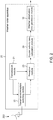
- FIG. 1 is a functional block diagram of a weather observation data generation module in the weather radar apparatus according to the first embodiment of the present invention.
- Fig. 2 is a functional block diagram of a weather radar apparatus according to a first embodiment of the present invention.
- the configuration of the weather radar apparatus 20 including the weather observation data generation module 10 will be described with reference to Fig. 2 .
- the structure and processing of the functions of the weather radar apparatus 20 other than the weather observation data generation module 10 are the same as those of known pulse Doppler radars that have been applied for and published by the applicant, and detailed description thereof will be omitted.
- the weather radar apparatus 20 includes a transmission module 21, a transmission/reception switching module 22, a reception module 23, a Doppler velocity data calculation module 24, and a weather observation data generation module 10.
- the transmission module 21 generates a pulse signal having a prescribed repetition period.
- the frequency of the carrier signal which is the source of the pulse signal is set according to the type of the observation object.
- observation objects are objects for weather observation, such as rain and clouds. Therefore, the frequency is set to reflect rain and clouds.
- the transmission module 21 outputs the pulse signal to the transmission/reception switching module 22 and outputs a part thereof to the reception module 23.
- the transmission/reception switching module 22 switches the transmission period and the reception period and repeats this operation.
- the transmission/reception switching module 22 outputs a pulse signal to an antenna 200 by connecting the transmission module 21 and the antenna 200 during the transmission period.
- the transmission/reception switching module 22 outputs the reflected signal of the pulse signal from the antenna 200 to the reception module 23 during the reception period.
- the antenna 200 transmits a pulse signal at a predetermined elevation angle while rotating on a horizontal plane around a rotation axis, and receives the reflected signal.
- the reception module 23 performs predetermined amplification processing or the like on the reflected signal.
- the reception module 23 calculates a pulse signal and a phase change amount, i.e. phase difference between the pulse signal and the reflected signal of a reflection signal to the pulse signal.
- the reception module 23 outputs the phase change amount to the Doppler velocity data calculation module 24.
- the Doppler velocity data calculation module 24 calculates Doppler velocity data based on the amount of phase change using, for example, a dual Pulse Repetition Frequencies (PRF) method.
- PRF Pulse Repetition Frequencies
- the Doppler velocity data is expressed by a Doppler velocity calculated for each position expressed in two dimensions of a distance direction and an azimuth direction with the position of the antenna 200 as a center position (reference point).
- the distance direction is a direction radially separating from the center position.
- the azimuth direction is a direction parallel to the rotation direction of the antenna 200.
- the Doppler velocity data calculation module 24 outputs the Doppler velocity data of one frequency (1 scan worth) of the antenna 200 as a set to the weather observation data generation module 10.
- the weather observation data generation module 10 includes a data processor module 11 and a data processor module 12.
- Each of the data processor module 11 and the data processor module 12 includes a hardware such as a processor for performing a process described later, and a program for realizing a process described later.
- the data processor module 11 corrects the loopback of the Doppler velocity data in the distance direction.
- the data processor module 12 replaces the exclusion value in the azimuth direction with respect to the Doppler velocity data.
- the weather observation data generation module 10 can detect erroneous values of Doppler velocity data in the distance direction and the azimuth direction caused by the phase change amount using the data processor module 11 and the data processor module 12. Then, the weather observation data generation module 10 can replace the erroneous value of the Doppler velocity data with a more accurate value corresponding to the observation object.
- the data processor module 11 is not necessarily configured, and may be omitted as long as the environment and the setting are such that the loopback in the distance direction does not occur.
- the data processor module 11 includes a median value calculation module 111, a difference value calculation module 112, a loopback detection module 113, and a correction module 114.
- the median value calculation module 111 acquires a plurality of Doppler velocity data arranged in a distance direction at one side of attention, and sets a target position (For example, the Dm of FIG. 3 ) in the distance direction in the bearing.
- the median value calculation module 111 acquires Doppler velocity data within a range (For example, the RGm of FIG. 3 ) of a predetermined distance on the center side with the target position as the distal end.
- the median value calculation module 111 calculates a median value of Doppler velocity data within this range. If there are a plurality of Doppler velocity data within this range, the median value calculation module 111 calculates a median value from the plurality of Doppler velocity data. However, if there is one Doppler velocity data within this range, the median value calculation module 111 sets the Doppler velocity data as the median value.
- the median value calculation module 111 outputs the median value to the difference value calculation module 112. At this time, the median value calculation module 111 correlates the Doppler velocity data of the target position with the median value and outputs them to the difference value calculation module 112.
- the median value calculation module 111 calculates a median value for each target position while shifting the target position along the distance direction in order from the position near the center. At this time, when the loopback detection module 113 detects the loopback, the median value calculation module 111 stops the shift of the target position and the calculation of the median value.
- the difference value calculation module 112 calculates a difference value (For example, V (Dm) in FIG. 3 ) between Doppler velocity data of a target position and a median value, and outputs the difference value to the loopback detection module 113.
- the loopback detection module 113 determines the occurrence of loopback in the distance direction by using the difference value. More specifically, when the difference value is equal to or greater than a threshold value for determining loopback, the loopback detection module 113 determines that loopback in the distance direction has occurred from the target position at corresponding time. Alternatively, when the difference value is less than the threshold value for determining loopback, the loopback detection module 113 determines that loopback in the distance direction has not occurred at the target position at corresponding time. The loopback detection module 113 further detects the reverse direction of the sign of the Doppler velocity data.
- the loopback detection module 113 outputs the determination result of the occurrence of loopback and the sign inversion direction to the correction module 114.
- the loopback detection module 113 also outputs the determination result of the occurrence of loopback to the median value calculation module 111.
- the correction module 114 corrects the Doppler velocity data arranged in the distance direction including the target position when the determination result of occurrence of loopback is obtained. More specifically, the correction module 114 corrects the Doppler velocity data beyond the target position among the Doppler velocity data arranged in the distance direction.
- the correction value is obtained by adding or subtracting a double value (For example, 2Vm in FIG. 3 ) of an upper limit value (For example, Vm in FIG. 3 ) of actually measurable Doppler velocity data determined according to the specifications of the transmission module 21 and the reception module 23 to or from the Doppler velocity data of the position to be corrected.
- the correction module 114 subtracts 2Vm from the Doppler velocity data (measured data).
- the correction module 114 adds 2Vm to the Doppler velocity data (measured data).
- the erroneous value can be corrected to an accurate value corresponding to actual weather conditions and the observation object.
- FIG. 3 is a diagram showing the concept of the distance direction loopback correction.
- the horizontal axis represents the distance
- the vertical axis represents the Doppler velocity data.
- the Doppler velocity data (measured data) are discontinuous only at the target position Dm. Further, the Doppler velocity data (measured data) at a plurality of positions in a predetermined range on the center side of the target position Dm is significantly different from the Doppler velocity data (measured data) at the target position Dm in value.
- the Doppler velocity data (measured data) at a plurality of positions in a predetermined range on the center side of the target position Dm is a negative value, and is substantially equal to the lower limit value - Vm of the Doppler velocity data.
- the Doppler velocity data (measured data) of the target position Dm is a positive value, and is substantially equal to the upper limit value + Vm of the Doppler velocity data.
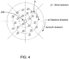
- FIG. 4 shows an example of a general uniform wind distribution.
- the direction of the wind is substantially the same at each position aligned in the distance direction, and the wind velocity varies constantly or continuously when local turbulence or the like does not occur. Therefore, as described above, it is not usually conceivable that the value of the Doppler velocity data becomes discontinuous only at the target position Dm at the plurality of positions arranged along the distance direction, and the value changes substantially. Therefore, at the target position Dm, it can be determined that loopback occurs due to the limit of the calculation process of the Doppler velocity data.
- the data processor module 11 realizes the above-described configuration and processing to detect the loopback at the target position Dm. At this time, as described above, the data processor module 11 detects the loopback while shifting the target position Dm sequentially from a position near the center to a distance. Thus, the data processor module 11 can definitely and accurately detect the occurrence of the loopback and the position where the loopback occurs.
- the data processor module 11 corrects the Doppler velocity data of each position beyond the target position Dm.
- the correction value is twice the upper limit value Vm as described above.
- the data processor module 11 calculates correction data by subtracting 2Vm from the Doppler velocity data (measured data) V (Dm) at the target position Dm. Then, the data processor module 11 similarly calculates correction data by subtracting 2Vm from Doppler velocity data (measured data) at each position farther than the target position Dm.
- the data processor module 12 includes an approximate function calculation module 121, an exclusion value detection module 122, and a data substitution module 123.
- the Doppler velocity data for one scan output from the data processor module 11 is input to the approximate function calculation module 121.
- the approximate function calculation module 121 acquires Doppler velocity data arranged in the azimuthal direction at a target distance.
- the distance of interest is set, for example, by a position where the number of Doppler velocity data arranged in the azimuth direction is large.
- the attention distance is set by a position where the distance from the center is short.
- the approximate function calculation module 121 calculates an approximate function for Doppler velocity data arranged in the azimuthal direction.
- the approximate function is preferably a periodic function such as a COS function or a SIN function, and may be a function representing a triangular wave. Note that a function whose value varies greatly at one point, and generate a discontinuous point of a value such as a rectangular wave or a saw tooth wave is not applied to the approximate function.
- the approximate function calculation module 121 outputs an approximate value of Doppler velocity data calculated by an approximate function at each position in the azimuth direction, and actual Doppler velocity data to an exclusion value detection module 122.
- the exclusion value detection module 122 compares the approximate value of Doppler velocity data calculated by the approximate function with actual measured Doppler velocity data for each position, and detects the exclusion value on the basis of the comparison result. Specifically, if the difference between the approximate value of the Doppler velocity data and the actually measured Doppler velocity data is equal to or greater than the threshold for detecting the exclusion value, the exclusion value detection module 122 detects the actually measured Doppler velocity data as the exclusion value at this position. Alternatively, if the difference between the approximate value of the Doppler velocity data and the actually measured Doppler velocity data is less than the threshold for detecting the exclusion value, the exclusion value detection module 122 does not detect the actually measured Doppler velocity data as the exclusion value at this position.
- the exclusion value detection module 122 outputs the approximate value of the Doppler velocity data, the actually measured Doppler velocity data, and the detection result of the exclusion value to the data substitution module 123.
- the data substitution module 123 replaces the exclusion value and actual Doppler velocity data at the detected position with an approximate value calculated by an approximate function based on the detection result of the exclusion value.
- the erroneous value can be replaced with an accurate value corresponding to actual weather conditions and an observation object.
- FIG. 5 is a diagram showing the concept of substitution of exclusion values in the azimuth direction.
- the horizontal axis represents a direction such as azimuthal angle
- the vertical axis represents Doppler velocity data.
- the Doppler velocity data are greatly separated from the approximate function composed of the periodic function (such as the COS function).
- the magnitude of the wind at each position aligned in the azimuthal direction is continuously increased and decreased with one cycle in the azimuthal direction if local turbulence or the like does not occur. That is, the change in the magnitude of the wind can be expressed by a cycle function in which one cycle in the azimuthal direction is one cycle.
- the value of the Doppler velocity data varies greatly locally at a plurality of positions arranged in the azimuthal direction. Therefore, at a position where the value of the Doppler velocity data largely changes, an erroneous phase change amount is detected due to noise or the like, and it can be determined that the erroneous Doppler velocity data is calculated.
- the data processor module 12 realizes the above-described configuration and processing to detect the exclusion value (actual measurement data with a black circle shown in FIG. 5 ) in the azimuth direction. Then, as shown in FIG. 5 , the data processor module 12 replaces the exclusion value with an approximate value represented by replacement data of a triangle mark based on the approximate function represented by a solid line.
- the data processor module 12 replaces the exclusion value with an approximate value represented by replacement data of a triangle mark based on the approximate function represented by a solid line.
- the weather observation data generation module 10 can output Doppler velocity data corresponding to the state of an observation object such as actual rain, clouds, etc.
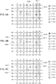
- FIGs. 6(A), 6(B), and. 6(C) are diagrams showing transitions in correction and replacement of Doppler velocity data when the configuration and processing of the weather observation data generation module of the present embodiment is used.
- FIG. 6(A) shows the distribution of the measured Doppler velocity data
- FIG. 6(B) shows the distribution of the Doppler velocity data after correction of turning back in the distance direction
- FIG. 6(C) shows the distribution of the Doppler velocity data after replacement of the exclusion value in the azimuth direction.
- R1, R2, R3, R4, R5, R6, and R7 are respective positions in the distance direction, wherein R1 is closest to the center and R7 is farthest from the center.
- ⁇ 1, ⁇ 2, ⁇ 3, ⁇ 4, ⁇ 5, ⁇ 6, and ⁇ 7 are positions (azimuthal angle) in the azimuth direction.
- the hatching at each position indicates the positive and negative values of the Doppler velocity data.
- V(3+), V(2+), and V(1+) are positive values and have a relationship of V(3+) > V(2 +) > V(1+).
- V (3-), V (2-), and V (1-) are negative values and have a relationship of V (3-) ⁇ V (2-) ⁇ V (1-).
- V (0) is substantially 0.
- a turn in the distance direction occurs in the region Ac 11 beyond the distance R4 in the direction ⁇ 7.
- a turn in the distance direction occurs in the range of the region Ac 12 beyond the distance R3 in the azimuth ⁇ 8.
- the loopback in the distance direction is detected and corrected as shown in FIG. 6(B) .
- Doppler velocity data continuing in the distance direction corresponding to actual weather conditions can be obtained along with the conditions of the observation object.
- the exclusion value is generated in the direction ⁇ 2 at the distance R5. Further, in the direction ⁇ 4 at the distance R4, an exclusion value is generated.
- the exclusion value in the azimuth direction is detected and corrected as shown in FIG. 6(C) .
- the Doppler velocity data continuing in the azimuthal direction corresponding to actual weather conditions can be obtained along with the conditions of the observation object.
- each processing of the weather observation data generation module 10 is realized by each individual function module.
- a program for performing a process described later may be stored and performed by a processor.
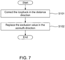
- FIG. 7 is a flowchart showing the basic processing performed by a processor for realizing the weather observation data generation module. That is, FIG. 7 is a flowchart showing a weather observation data generation method. The specific processing contents have been described above, and a detailed description thereof will be omitted.
- the processor corrects the loopback in the distance direction using the Doppler velocity data arranged in the distance direction (S101).
- the processor replaces the exclusion value in the azimuth direction by using the Doppler velocity data arranged in the azimuth direction (S102)
- FIG. 8 is a flowchart showing the process of correcting the loopback in the distance direction.
- the processor acquires Doppler velocity data arranged in the distance direction at a target azimuth (S201).
- the processor sets a target position (corresponding to Dm in FIG. 3 ) (S202).
- the processor calculates the median value of the Doppler velocity data in a predetermined range (corresponding to the RGm in Figure 3 ) on the center side of the target position (S203).
- the processor calculates a difference value between the value of the Doppler velocity data of the target position and the median value (S204).
- the processor corrects the Doppler velocity data of each position beyond the target position by using the correction value based on the upper limit value of the measured value of the Doppler velocity data (S206).
- the processor shifts the target position far away (S207), and repeats the processes after step S203.
- FIG. 9 is a flowchart showing the process of replacing the exclusion value in the azimuth direction.
- the processor acquires Doppler velocity data arranged in the azimuthal direction at a target distance (S301).
- the processor calculates an approximate function using the Doppler velocity data (S302).
- the approximate function is a periodic function.
- the processor calculates a difference value between actually measured Doppler velocity data and an approximate value calculated by an approximate function (S303). If the difference value is equal to or greater than the threshold value for detecting the exclusion value (S304: YES), the processor detects the actually measured Doppler velocity data as the exclusion value (S305). The processor replaces the exclusion value with an approximate value for the position calculated by the approximate function (S306).
- the processor does not perform replacement and uses the measured Doppler velocity data as it is.
- FIG. 10 is a functional block diagram of a weather observation data generation module of a weather radar apparatus according to a second embodiment of the present invention.
- the weather radar apparatus according to the second embodiment differs from the weather radar apparatus 20 according to the first embodiment in the configuration of the weather observation data generation module 10A shown in Fig. 10 , and the other configurations are the same as those of the weather radar apparatus 20 according to the first embodiment. Therefore, a description of the same portion is omitted.
- the weather observation data generation module 10A differs from the weather observation data generation module 10 according to the first embodiment in that a dummy data generation module 13 and a dummy data addition module 14 are added as the functional blocks.
- the weather observation data generation module 10A repeats the correction of the loopback in the distance direction by the data processor module 11 and the replacement of the exclusion value in the azimuth direction by the data processor module 12 with the processing of the dummy data generation module 13 and the dummy data addition module 14 interposed therebetween.
- the dummy data generation module 13 acquires Doppler velocity data for the entire circumference (1 scan worth) in the azimuth direction at a prescribed position in the distance direction.At this time, it is preferable that the dummy data generation module 13 compares the number of Doppler velocity data arranged in the azimuthal direction at each position in the distance direction, and selects a distance at which the Doppler velocity data arranged in the azimuthal direction is less defective.
- the dummy data generation module 13 then calculates an approximate function as a periodic function from a plurality of Doppler velocity data arranged in the azimuth direction. Thus, the dummy data generation module 13 can approximately reproduce the wind state in each azimuth direction from the measured Doppler velocity data.
- the dummy data generation module 13 calculates an approximate value to the azimuth direction over the entire circumference based on the approximate function.
- the dummy data generation module 13 outputs the generated approximate value over the entire circumference to a dummy data addition module 14 as dummy data.
- the dummy data addition module 14 adds dummy data (Approximate value of each bearing over the entire circumference) as Doppler velocity data at a position closest to the center in the distance direction.
- a dummy data addition module 14 outputs Doppler velocity data for one scan added with the dummy data to the data processor module 11.
- the weather observation data generation module 10A performs the following processes.
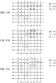
- FIGs. 11(A), 11(B), and 11(C) are diagrams showing Doppler velocity data during the first correction and replacement processing performed by the weather observation data generation module.
- FIG. 11(A) shows the first Doppler velocity data
- FIG. 11(B) shows the Doppler velocity data after the first correction of the loopback in the distance direction
- FIG. 11(C) shows Doppler velocity data after replacement of the exclusion value in the first azimuth direction.
- the Doppler velocity data are hatched for each of positive value, substantially 0, and negative value.
- 11(A), 11(B), and 11(C) show a region from a distance R1, which is a module of the distance direction, to a distance R7, and a region from an azimuth ⁇ 1, which is a part of the azimuth direction, to an azimuth ⁇ 8 as a target region.
- the data processor module 11 uses the actual measured Doppler velocity data to which the dummy data is not added to correct the loopback in the distance direction as described above. For example, when the actually measured Doppler velocity data as shown in FIG. 11 (A) is acquired, the data processor module 11 detects a turn in the distance direction at the position of the distance R4 of the azimuth ⁇ 4, the position of the distance R7 of the azimuth ⁇ 5, and the position of the distance R7 of the azimuth ⁇ 6, and performs correction. As a result, as shown in FIG. 11 (B) , the Doppler velocity data of the position of the distance R4 of the azimuth ⁇ 4, the position of the distance R7 of the azimuth ⁇ 5, and the position of the distance R7 of the azimuth ⁇ 6 are corrected.
- the data processor module 12 replaces the exclusion value in the azimuth direction using the Doppler velocity data after the loopback correction, as described above.
- the data processor module 12 detects the Doppler velocity data of the position of the azimuth ⁇ 5 and the position of the azimuth ⁇ 6 of the distance R5, the position of the azimuth ⁇ 8 from the azimuth ⁇ 5 of the distance R6, and the position of the azimuth ⁇ 5 and the position of the azimuth ⁇ 6 of the distance R7 as exclusion values.
- the data processor module 12 deletes the Doppler velocity data to substitute the replacement processing. By this processing, the Doppler velocity data that is estimated to be wrong in a predetermined area is deleted. As a result, as shown in FIG. 11(C) , the Doppler velocity data for the position of the azimuth ⁇ 5 and the position of the azimuth ⁇ 6 of the distance R5, the position of the azimuth ⁇ 5 to the azimuth ⁇ 8 of the distance R6, and the position of the azimuth ⁇ 5 and the position of the azimuth ⁇ 6 of the distance R7 are deleted.
- FIGs.12 (A), 12 (B), and 12 (C) are diagrams for explaining the concept of generating dummy data.
- FIG. 12(A) shows Doppler velocity data to be approximated for generating dummy data
- FIG. 12(B) shows an example of the approximate function
- FIG. 12 (C) shows an example of dummy data.
- the Doppler velocity data are hatched for each of positive value, substantially 0, and negative value. Further, FIGs.
- 12 (A), 12 (B), and 12 (C) show a region from the distance R1 which is a part of the distance direction to the distance R7, and from the azimuth ⁇ A1 to the azimuth ⁇ A16 over the entire circumference in the azimuth direction as a target region.
- the directions ⁇ 1 to ⁇ 8 shown in FIGs. 11(A), 11(B) and 11(C) correspond to the directions ⁇ A3 to ⁇ A4 shown in FIGs. 12(A) and 12(C) .
- the dummy data generation module 13 calculates an approximate function using Doppler velocity data arranged in the azimuthal direction at a predetermined position in the distance direction.
- the dummy data generation module 13 is not limited to one position in the distance direction, but may be applied to a plurality of positions adjacent to each other.
- the Doppler velocity data for calculating the approximate function for each azimuth may be, for example, an average value of the Doppler velocity data at a plurality of positions in the distance direction.
- the dummy data generation module 13 calculates an approximate function composed of the periodic function shown in FIG. 12(B) using the Doppler velocity data arranged in the azimuthal direction such as the distance R4, the distance R5, and the distance R6.
- the approximate function is a COS function or a SIN function.
- the approximate function may be a periodic function whose value does not change abruptly.
- the dummy data generation module 13 calculates an approximate value of the Doppler velocity data at each position in the azimuth direction as shown in FIG. 12(C) by using the calculated approximate function.
- a dummy data generation module 13 sets the approximate value to dummy data.
- FIG. 13(A) is a diagram that shows Doppler velocity data in which the first correction and replacement are completed and dummy data are added.
- the Doppler velocity data is hatched for each of positive value, substantially 0, and negative value.
- FIG. 13 (A) further shows a region from the distance R1, which is a part of the distance direction, to the distance R7, and a region from the azimuth ⁇ 1, which is a part of the azimuth direction, to the azimuth ⁇ 8 as a target region.
- the dummy data addition module 14 adds dummy data corresponding to a target region as Doppler velocity data at a position closest to the center in the distance direction among dummy data over all directions generated by a dummy data generation module 13. For example, when the dummy data shown in FIG. 12 (C) is obtained, the dummy data addition module 14 adds dummy data having an orientation ⁇ 1 to an orientation ⁇ 8 at a distance R0 ( ⁇ R1) as Doppler velocity data, as shown in FIG. 13(A) . Further, as shown in FIG. 13 (A) , the dummy data addition module 14 adds the Doppler velocity data deleted in the replacement of the first exclusion value performed by the data processor module 12 as the dummy data for the second loopback correction.
- FIGs.13 (B) and 13 (C) are diagrams showing Doppler velocity data in the second correction and replacement processing performed by the weather observation data generation module.
- FIG. 13(B) is a diagram that shows the Doppler velocity data after the second correction of the loopback in the distance direction
- FIG. 13(C) is a diagram that shows Doppler velocity data after replacement of the exclusion value in the second azimuth direction.
- the Doppler velocity data are hatched for each of positive value, substantially 0, and negative value
- 13 (B) and 13 (C) show a region from a distance R1, which is a part of the distance direction, to a distance R7, and a region from an azimuth ⁇ 1, which is a part of the azimuth direction, to an azimuth ⁇ 8 as a target region.
- the data processor module 11 performs a loopback correction in the distance direction as described above using the Doppler velocity data to which the first correction and replacement are performed and dummy data are added. For example, as shown in FIG. 13(A) , when the Doppler velocity data in which the first correction, replacement, and addition of dummy data are performed is acquired, the data processor module 11 detects a turn in the distance direction at the position of the distance R5 of the azimuth ⁇ 5, the position of the distance R5 of the azimuth ⁇ 6, the position of the distance R6 of the azimuth ⁇ 7, and the position of the distance R6 of the azimuth ⁇ 8, and performs correction.
- the loopback is corrected for the Doppler velocity data with respect to the distance in the distance direction starting from the position of the distance R5 of the azimuth ⁇ 5, the position of the distance R5 of the azimuth ⁇ 6, the position of the distance R6 of the azimuth ⁇ 7, and the position of the distance R6 of the azimuth ⁇ 8.
- the data processor module 12 replaces the exclusion value in the azimuth direction as described above using the Doppler velocity data after the second loopback correction.
- the data processor module 12 detects the Doppler velocity data as an exclusion value.
- the Doppler velocity data after the replacement of the exclusion value is the same as the Doppler velocity data before the replacement of the exclusion value.
- the weather observation data generation module 10A can accurately detect and correct the turn-back according to wind conditions at the arrangement position.
- each processing of the weather observation data generation module 10A is realized by each individual functional module.
- a program for performing a process described later may be stored and performed by the processor.
- FIG. 14 is a flow chart showing basic processing performed by the processor for realizing the weather observation data generation module. The specific processing contents have been described above, and a detailed description thereof will be omitted.
- the processor corrects the first loopback in the distance direction using the Doppler velocity data arranged in the distance direction (S101).
- the processor replaces the exclusion value in the azimuth direction for the first time using the Doppler velocity data arranged in the azimuth direction (S102).
- the processor calculates an approximate function for generating dummy data (S104).
- the processor generates dummy data from an approximate value using the approximate function (S105).
- the processor adds dummy data to the position closest to the center of the Doppler velocity data after the first correction and replacement (S106).
- the processor corrects the second loopback in the distance direction by using the Doppler velocity data after the first correction, replacement, and addition of the dummy data (S101). Next, the processor performs a second replacement of the exclusion value in the azimuth direction (S102).
- FIG. 15 is a functional block diagram of the weather observation data generation module of a weather radar according to the third embodiment of the present invention.
- the weather radar according to the third embodiment differs from the weather radar apparatus 20 according to the first embodiment in the configuration of the weather observation data generation module 10B shown in Fig. 15 , and the other configurations are the same as those of the weather radar apparatus 20 according to the first embodiment. Therefore, a description of the same portion is omitted.
- the weather observation data generation module 10B according to the third embodiment differs from the weather observation data generation module 10 according to the first embodiment in that an abnormal weather detection module 15 is added thereto.
- the other configuration of the weather observation data generation module 10B is the same as that of the weather observation data generation module 10, and a description of the same portion is omitted.
- the exclusion value detection module 122 outputs the exclusion value, to the abnormal weather detection module 15 upon detection of the same. Along with, the exclusion value detection module 122 outputs the distance direction and the direction in which the exclusion value is detected, to the abnormal weather detection module 15.
- the abnormal weather detection module 15 notifies the occurrence of abnormal weather upon receiving the exclusion value as input.
- the notification may be a display, a sound, a buzzer sound or the like which can be recognized by the operator.
- the detection of the exclusion value assumes that the wind is uniform. Therefore, at the position where the exclusion value was detected, it is possible that the exclusion value was generated not by noise but by local abnormal weather. Therefore, the detection of the exclusion value is also used for the detection of abnormal weather, whereby the abnormal weather can be detected while performing steady weather observation.
- the abnormal weather detection module 15 also notifies the position in which the exclusion value is detected. Thus, the occurrence position of the abnormal weather can be notified to the operator.
- the abnormal weather detection module 15 may detect abnormal weather when a plurality of positions where the exclusion values are detected are adjacent to each other and the number of positions exceeds a predetermined number. Thus, the exclusion value due to noise and the exclusion value due to abnormal weather can be discriminated. Therefore, the abnormal weather detecting module 15 can more accurately detect and notify the abnormal weather.
- the configuration of the abnormal weather detection module 15 according to the third embodiment can be applied to a weather observation data generation module having only the data processor module 12 and not the data processor module 11, as also shown in the first embodiment.
- the weather radar can obtain an image for weather observation.
- the weather radar is provided with a display image generation module at a subsequent stage of the weather observation data generation module.
- the display image generation module generates a display image of the weather observation data with the weather radar as a center by using a color or luminance corresponding to the value of the Doppler velocity data.
- the display image is displayed on a display device, for example.
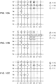
- FIGs.16 (A), 16 (B), and 16 (C) are diagrams showing weather observation data when the weather observation data generation module according to the first embodiment is used.
- weather observation data is generated in gray scale by using the value of Doppler velocity data (Doppler velocity data).
- FIG. 16(A) shows weather observation data based on measured Doppler velocity data.
- FIG.16(B) shows weather observation data based on Doppler velocity data after correction of turning back in the distance direction.
- FIG.16 (C) shows weather observation data based on Doppler velocity data after replacement of exclusion values in the azimuth direction.
- FIGs.17(A), 17(B), 17(C) , 18(A), and 18(B) are diagrams showing weather observation data when the weather observation data generation module according to the second embodiment is used.
- weather observation data is generated in gray scale using the value of Doppler velocity data.
- FIG. 17 (A) shows weather observation data based on measured Doppler velocity data.
- FIG. 17 (B) shows weather observation data based on the Doppler velocity data after the first correction of turning back in the distance direction.
- FIG. 17 (C) shows weather observation data based on Doppler velocity data after replacement of the exclusion value in the first azimuth direction.
- FIG. 18(A) is weather observation data based on the Doppler velocity data after the second back-and-forth correction in the distance direction.
- FIG. 18 (B) shows weather observation data based on Doppler velocity data after replacement of the second azimuthal exclusion value.
- the exclusion value in the azimuth direction at the local position P (Ac2) is replaced by replacing the exclusion value in the azimuth direction for the first time by the data processor module 12 of the weather observation data generation module 10A.
- the exclusion values continuously generated in the azimuth direction are deleted.
- dummy data are generated based on an approximate function calculated from Doppler velocity data arranged in the azimuthal direction by performing processing of a dummy data generation module 13 of a weather observation data generation module 10A. Then, dummy data are added to the position closest to the center DD by performing the processing of the dummy data addition module 14.
- the loopback in the distance direction in the region R(Ac1) is recorrected.
- the added dummy data serves as a reference for turning back in the distance direction with respect to the region Rg which includes the region R (Acl) and is defined by the azimuth direction in which the measured Doppler velocity data is missing. Therefore, turning back in the distance direction in the region R (Acl) is accurately performed according to actual weather conditions.
- the second exclusion value in the azimuth direction is substituted by the data processor module 12 of the weather observation data generation module 10A, whereby the exclusion value in the azimuth direction at the local position P (Ac2) is re-replaced.
- the weather observation data generation module 10A accurate and easily visible weather observation data corresponding to actual weather conditions can be obtained.
- the weather observation data generation module 10A even if there is a defect in the Doppler velocity data, accurate and easily visible weather observation data corresponding to actual weather conditions can be more surely obtained.
- a mode in which a median value is used for detection of loopback in the distance direction is shown.
- it may be a statistical reference value (statistically plausible representative values) for detection of loopback, for example, an average value or a mode value.
- the median value even if the Doppler velocity data having locally different values exist in a predetermined range on the center side of the target position, the reference value for detecting the loopback does not largely change. Thus, the detection of the loopback is performed more accurately.
- a value e.g., ratio, etc. which can compare the value of the Doppler velocity data of the target position with a statistical reference value such as a median value may be used.
- the difference value is used for the detection of the exclusion value, but a value (e.g., ratio, etc.) by which the value of the Doppler velocity data can be compared with the approximate value may be used.
- the above-described periodic function for approximation is a function in which one cycle in the azimuthal direction is one cycle, but when the wind tendency due to the season or the like is known at the position where the weather radar is arranged, an approximate function corresponding to the wind tendency may be appropriately used.
- an approximate function corresponding to the wind tendency may be appropriately used.
- two functions for making the half circumference of the azimuth direction may be used as an approximate function.
- the data substitution module 123 of the exclusion value may not be provided.
- the data substitution module 123 for the exclusion value may perform processing for deleting the exclusion value instead of data substitution for the exclusion value.
- All of the processes described herein may be embodied in, and fully automated via, software code modules executed by a computing system that includes one or more computers or processors.
- the code modules may be stored in any type of non-transitory computer-readable medium or other computer storage device. Some or all the methods may be embodied in specialized computer hardware. Many other variations than those described herein will be apparent from this disclosure. For example, depending on the embodiment, certain acts, events, or functions of any of the algorithms described herein can be performed in a different sequence, can be added, merged, or left out altogether (e.g., not all described acts or events are necessary for the practice of the algorithms).
- acts or events can be performed concurrently, e.g., through multi-threaded processing, interrupt processing, or multiple processors or processor cores or on other parallel architectures, rather than sequentially.
- different tasks or processes can be performed by different machines and/or computing systems that can function together.
- the various illustrative logical blocks and modules described in connection with the embodiments disclosed herein can be implemented or performed by a machine, such as a processor.
- a processor can be a microprocessor, but in the alternative, the processor can be a controller, microcontroller, or state machine, combinations of the same, or the like.
- a processor can include electrical circuitry configured to process computer-executable instructions.
- a processor includes an application specific integrated circuit (ASIC), a field programmable gate array (FPGA) or other programmable device that performs logic operations without processing computer-executable instructions.
- a processor can also be implemented as a combination of computing devices, e.g., a combination of a digital signal processor (DSP) and a microprocessor, a plurality of microprocessors, one or more microprocessors in conjunction with a DSP core, or any other such configuration.
- DSP digital signal processor
- a processor may also include primarily analog components.
- a computing environment can include any type of computer system, including, but not limited to, a computer system based on a microprocessor, a mainframe computer, a digital signal processor, a portable computing device, a device controller, or a computational engine within an appliance, to name a few.
- Disjunctive language such as the phrase "at least one of X, Y, or Z," unless specifically stated otherwise, is otherwise understood with the context as used in general to present that an item, term, etc., may be either X, Y, or Z, or any combination thereof (e.g., X, Y, and/or Z). Thus, such disjunctive language is not generally intended to, and should not, imply that certain embodiments require at least one of X, at least one of Y, or at least one of Z to each be present.
- a processor configured to carry out recitations A, B and C can include a first processor configured to carry out recitation A working in conjunction with a second processor configured to carry out recitations B and C.
- a processor configured to carry out recitations A, B and C can include a first processor configured to carry out recitation A working in conjunction with a second processor configured to carry out recitations B and C.
- horizontal is defined as a plane parallel to the plane or surface of the floor of the area in which the system being described is used or the method being described is performed, regardless of its orientation.
- floor can be interchanged with the term “ground” or “water surface.”
- vertical refers to a direction perpendicular to the horizontal as just defined. Terms such as “above,” “below,” “bottom,” “top,” “side,” “higher,” “lower,” “upper,” “over,” and “under,” are defined with respect to the horizontal plane.
- connection should be construed, unless otherwise noted, to include removable, moveable, fixed, adjustable, and/or releasable connections or attachments.
- the connections/attachments can include direct connections and/or connections having intermediate structure between the two components discussed.
- Numbers preceded by a term such as “approximately,” “about,” and “substantially” as used herein include the recited numbers, and also represent an amount close to the stated amount that still performs a desired function or achieves a desired result.
- the terms “approximately,” “about,” and “substantially” may refer to an amount that is within less than 10% of the stated amount.
- Features of embodiments disclosed herein preceded by a term such as “approximately,” “about,” and “substantially” as used herein represent the feature with some variability that still performs a desired function or achieves a desired result for that feature.
Landscapes
- Engineering & Computer Science (AREA)
- Radar, Positioning & Navigation (AREA)
- Remote Sensing (AREA)
- Physics & Mathematics (AREA)
- Computer Networks & Wireless Communication (AREA)
- General Physics & Mathematics (AREA)
- Electromagnetism (AREA)
- Radar Systems Or Details Thereof (AREA)
Abstract
Description
- The present invention relates to a weather radar apparatus for observing a state of an observation object related to weather such as clouds and rain by using Doppler velocity data.
- At present, various kinds of weather radar devices are practically used. For example,
Patent Document 1 andPatent Document 2 describe weather radar devices using Doppler velocity data. - The weather radar described in Patent Document 1transmits a pulse signal to a cloud or rain to be observed, and receives the reflected signal to detect the amount of phase change. The weather radar described in
Patent Document 2 calculates Doppler velocity data of observation objects such as clounds and rain from the phase change amount. The weather radar described inPatent Document 1 observes the state of the observation objects such as clouds and rain from the Doppler velocity data. -
- [Patent Document 1] - Japanese Patent Application Publication:
JP2014-173865 - [Patent Document 2] - Japanese Patent Application Publication:
JP2013-205151 - However, the observed phase change amount of the pulse signal becomes discontinuous when the pulse signal exceeds one wavelength. The amount of phase change of the pulse signal observed may be discontinuous due to the influence of noise or the like.
- Due to such a discontinuous change in the amount of phase change, the Doppler velocity data becomes an erroneous value.
- Accordingly, it is an object of the present invention to provide a technique capable of detecting an erroneous value of the Doppler velocity data even if the value of the Doppler velocity data becomes erroneous due to a discontinuous change in the amount of phase change.
- The weather radar apparatus includes an approximate function calculation module, an exclusion value detection module, and a data substitution module. The approximate function calculation module calculates an approximate function by using a plurality of Doppler velocity data arranged in an azimuth direction among Doppler velocity data of an observation object used for weather observation obtained for each position expressed in two-dimensional coordinates in a distance direction and an azimuth direction with an antenna position as a center. The exclusion value detection module detects an exclusion value by using a plurality of Doppler velocity data arranged in the azimuth direction and the value of an approximate function.
- In this configuration, the Doppler velocity data of an observation object (For example, clouds and rain) used for weather observation continuously changes, and the weather radar detects discontinuous points by using an approximate function. By detecting such a discontinuous portion, for example, the weather radar device replaces the Doppler velocity data of the discontinuous portion with an approximate value calculated by an approximate function.
- According to the present invention, even if the Doppler velocity data has an erroneous value due to a discontinuous change in the amount of phase change, the incorrect Doppler velocity data can be accurately detected.
-
-
FIG. 1 is a functional block diagram of a weather observation data generation module in a weather radar apparatus according to a first embodiment of the present invention; -
FIG. 2 is a functional block diagram of a weather radar apparatus according to a first embodiment of the present invention; -
FIG. 3 is a diagram showing the concept of distance direction loopback correction; -
FIG. 4 shows an example of a general uniform wind distribution; -
FIG. 5 is a diagram illustrating the concept of substitution of exclusion values in the azimuthal direction; -
FIGs. 6(A), 6(B), and 6(C) are diagrams showing transitions of correction and replacement of Doppler velocity data when the configuration and processing of the weather observation data generation module of the present embodiment is used; -
FIG. 7 is a flow chart showing basic processing performed by the processor implementing the weather observation data generation module; -
FIG. 8 is a flowchart showing the process of correcting loopback in the distance direction; -
FIG. 9 is a flowchart showing the process of replacing an exclusion value in the azimuth direction; -
FIG. 10 is a functional block diagram of a weather observation data generation module of a weather radar apparatus according to a second embodiment of the present invention; -
FIGs. 11(A), 11(B), and 11(C) are diagrams showing Doppler velocity data during the first correction and replacement processing performed by the weather observation data generation module; -
FIGs. 12(A), 12(B), and 12(C) are diagrams illustrating the concept of generating dummy data; -
FIG. 13(A) is a diagram showing Doppler velocity data in which the first correction and replacement are completed and dummy data are added, andFIGs. 13(B) and 13(C) are diagrams showing Doppler velocity data in the second correction and replacement processing performed by the weather observation data generation module; -
FIG. 14 is a flowchart showing basic processing performed by a processor implementing the weather observation data generation module; -
FIG. 15 is a functional block diagram of a weather observation data generation module of a weather radar apparatus according to a third embodiment of the present invention; -
FIGs. 16(A), 16(B) and 16(C) are diagrams showing weather observation data when the weather observation data generation module according to the first embodiment is used; -
FIGs. 17(A), 17(B) and 17(C) are diagrams showing weather observation data when the weather observation data generation module according to the second embodiment is used; and -
FIGs. 18(A) and 18(B) are diagrams showing weather observation data when the weather obserbation data generation module according to the second embodiment is used. - A weather radar apparatus according to a first embodiment of the present invention will be described with reference to the drawings.
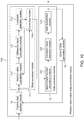
Fig. 1 is a functional block diagram of a weather observation data generation module in the weather radar apparatus according to the first embodiment of the present invention.Fig. 2 is a functional block diagram of a weather radar apparatus according to a first embodiment of the present invention. - First, the configuration of the
weather radar apparatus 20 including the weather observationdata generation module 10 will be described with reference toFig. 2 . The structure and processing of the functions of theweather radar apparatus 20 other than the weather observationdata generation module 10 are the same as those of known pulse Doppler radars that have been applied for and published by the applicant, and detailed description thereof will be omitted. - As shown in
FIG. 2 , theweather radar apparatus 20 includes atransmission module 21, a transmission/reception switching module 22, areception module 23, a Doppler velocitydata calculation module 24, and a weather observationdata generation module 10. - The
transmission module 21 generates a pulse signal having a prescribed repetition period. The frequency of the carrier signal which is the source of the pulse signal is set according to the type of the observation object. In theweather radar apparatus 20 of the present embodiment, observation objects are objects for weather observation, such as rain and clouds. Therefore, the frequency is set to reflect rain and clouds. - The
transmission module 21 outputs the pulse signal to the transmission/reception switching module 22 and outputs a part thereof to thereception module 23. The transmission/reception switching module 22 switches the transmission period and the reception period and repeats this operation. - Specifically, the transmission/
reception switching module 22 outputs a pulse signal to anantenna 200 by connecting thetransmission module 21 and theantenna 200 during the transmission period. On the other hand, the transmission/reception switching module 22 outputs the reflected signal of the pulse signal from theantenna 200 to thereception module 23 during the reception period. - The
antenna 200 transmits a pulse signal at a predetermined elevation angle while rotating on a horizontal plane around a rotation axis, and receives the reflected signal. Thereception module 23 performs predetermined amplification processing or the like on the reflected signal. - The
reception module 23 calculates a pulse signal and a phase change amount, i.e. phase difference between the pulse signal and the reflected signal of a reflection signal to the pulse signal. Thereception module 23 outputs the phase change amount to the Doppler velocitydata calculation module 24. - The Doppler velocity
data calculation module 24 calculates Doppler velocity data based on the amount of phase change using, for example, a dual Pulse Repetition Frequencies (PRF) method. - The Doppler velocity data is expressed by a Doppler velocity calculated for each position expressed in two dimensions of a distance direction and an azimuth direction with the position of the
antenna 200 as a center position (reference point). The distance direction is a direction radially separating from the center position. The azimuth direction is a direction parallel to the rotation direction of theantenna 200. - The Doppler velocity
data calculation module 24 outputs the Doppler velocity data of one frequency (1 scan worth) of theantenna 200 as a set to the weather observationdata generation module 10. - As shown in
FIG. 1 , the weather observationdata generation module 10 includes adata processor module 11 and adata processor module 12. Each of thedata processor module 11 and thedata processor module 12 includes a hardware such as a processor for performing a process described later, and a program for realizing a process described later. - In general, the
data processor module 11 corrects the loopback of the Doppler velocity data in the distance direction. Thedata processor module 12 replaces the exclusion value in the azimuth direction with respect to the Doppler velocity data. - The weather observation
data generation module 10 can detect erroneous values of Doppler velocity data in the distance direction and the azimuth direction caused by the phase change amount using thedata processor module 11 and thedata processor module 12. Then, the weather observationdata generation module 10 can replace the erroneous value of the Doppler velocity data with a more accurate value corresponding to the observation object. - It should be noted, that the
data processor module 11 is not necessarily configured, and may be omitted as long as the environment and the setting are such that the loopback in the distance direction does not occur. - (Configuration of
data processor module 11 and correction of distance direction loopback) - As shown in
FIG. 1 , thedata processor module 11 includes a medianvalue calculation module 111, a differencevalue calculation module 112, aloopback detection module 113, and acorrection module 114. - The median
value calculation module 111 acquires a plurality of Doppler velocity data arranged in a distance direction at one side of attention, and sets a target position (For example, the Dm ofFIG. 3 ) in the distance direction in the bearing. - The median
value calculation module 111 acquires Doppler velocity data within a range (For example, the RGm ofFIG. 3 ) of a predetermined distance on the center side with the target position as the distal end. The medianvalue calculation module 111 calculates a median value of Doppler velocity data within this range. If there are a plurality of Doppler velocity data within this range, the medianvalue calculation module 111 calculates a median value from the plurality of Doppler velocity data. However, if there is one Doppler velocity data within this range, the medianvalue calculation module 111 sets the Doppler velocity data as the median value. The medianvalue calculation module 111 outputs the median value to the differencevalue calculation module 112. At this time, the medianvalue calculation module 111 correlates the Doppler velocity data of the target position with the median value and outputs them to the differencevalue calculation module 112. - The median
value calculation module 111 calculates a median value for each target position while shifting the target position along the distance direction in order from the position near the center. At this time, when theloopback detection module 113 detects the loopback, the medianvalue calculation module 111 stops the shift of the target position and the calculation of the median value. - The difference
value calculation module 112 calculates a difference value (For example, V (Dm) inFIG. 3 ) between Doppler velocity data of a target position and a median value, and outputs the difference value to theloopback detection module 113. - The
loopback detection module 113 determines the occurrence of loopback in the distance direction by using the difference value. More specifically, when the difference value is equal to or greater than a threshold value for determining loopback, theloopback detection module 113 determines that loopback in the distance direction has occurred from the target position at corresponding time. Alternatively, when the difference value is less than the threshold value for determining loopback, theloopback detection module 113 determines that loopback in the distance direction has not occurred at the target position at corresponding time. Theloopback detection module 113 further detects the reverse direction of the sign of the Doppler velocity data. - The
loopback detection module 113 outputs the determination result of the occurrence of loopback and the sign inversion direction to thecorrection module 114. Theloopback detection module 113 also outputs the determination result of the occurrence of loopback to the medianvalue calculation module 111. - The
correction module 114 corrects the Doppler velocity data arranged in the distance direction including the target position when the determination result of occurrence of loopback is obtained. More specifically, thecorrection module 114 corrects the Doppler velocity data beyond the target position among the Doppler velocity data arranged in the distance direction. The correction value is obtained by adding or subtracting a double value (For example, 2Vm inFIG. 3 ) of an upper limit value (For example, Vm inFIG. 3 ) of actually measurable Doppler velocity data determined according to the specifications of thetransmission module 21 and thereception module 23 to or from the Doppler velocity data of the position to be corrected. When the Doppler velocity data is inverted from a negative value to a positive value, thecorrection module 114 subtracts 2Vm from the Doppler velocity data (measured data). Alternatively, when the Doppler velocity data is inverted from a positive value to a negative value, thecorrection module 114 adds 2Vm to the Doppler velocity data (measured data). - With such a configuration and processing, even if the Doppler velocity data becomes an erroneous value due to the loopback in the distance direction, the erroneous value can be corrected to an accurate value corresponding to actual weather conditions and the observation object.
-
FIG. 3 is a diagram showing the concept of the distance direction loopback correction. InFIG. 3 , the horizontal axis represents the distance, and the vertical axis represents the Doppler velocity data. - As illustrated in
FIG. 3 , the Doppler velocity data (measured data) are discontinuous only at the target position Dm. Further, the Doppler velocity data (measured data) at a plurality of positions in a predetermined range on the center side of the target position Dm is significantly different from the Doppler velocity data (measured data) at the target position Dm in value. For example, inFIG. 3 , the Doppler velocity data (measured data) at a plurality of positions in a predetermined range on the center side of the target position Dm is a negative value, and is substantially equal to the lower limit value - Vm of the Doppler velocity data. Alternatively, the Doppler velocity data (measured data) of the target position Dm is a positive value, and is substantially equal to the upper limit value + Vm of the Doppler velocity data. -
FIG. 4 shows an example of a general uniform wind distribution. As shown inFIG. 4 , , the direction of the wind is substantially the same at each position aligned in the distance direction, and the wind velocity varies constantly or continuously when local turbulence or the like does not occur. Therefore, as described above, it is not usually conceivable that the value of the Doppler velocity data becomes discontinuous only at the target position Dm at the plurality of positions arranged along the distance direction, and the value changes substantially. Therefore, at the target position Dm, it can be determined that loopback occurs due to the limit of the calculation process of the Doppler velocity data. - Using this principle, the
data processor module 11 realizes the above-described configuration and processing to detect the loopback at the target position Dm. At this time, as described above, thedata processor module 11 detects the loopback while shifting the target position Dm sequentially from a position near the center to a distance. Thus, thedata processor module 11 can definitely and accurately detect the occurrence of the loopback and the position where the loopback occurs. - Then, the
data processor module 11 corrects the Doppler velocity data of each position beyond the target position Dm. In this case, the correction value is twice the upper limit value Vm as described above. - In
FIG. 3 , since the Doppler velocity data is inverted from a negative value to a positive value at the target position Dm, thedata processor module 11 calculates correction data by subtracting 2Vm from the Doppler velocity data (measured data) V (Dm) at the target position Dm. Then, thedata processor module 11 similarly calculates correction data by subtracting 2Vm from Doppler velocity data (measured data) at each position farther than the target position Dm. - As a result, as shown in
FIG. 3 , continuous and accurate Doppler velocity data corresponding to conditions of the observation object such as actual rain and clouds can be obtained in the distance direction. - Referring back to
FIG. 1 , thedata processor module 12 includes an approximatefunction calculation module 121, an exclusionvalue detection module 122, and adata substitution module 123. - The Doppler velocity data for one scan output from the
data processor module 11 is input to the approximatefunction calculation module 121. The approximatefunction calculation module 121 acquires Doppler velocity data arranged in the azimuthal direction at a target distance. The distance of interest is set, for example, by a position where the number of Doppler velocity data arranged in the azimuth direction is large. Alternatively, the attention distance is set by a position where the distance from the center is short. - The approximate
function calculation module 121 calculates an approximate function for Doppler velocity data arranged in the azimuthal direction. The approximate function is preferably a periodic function such as a COS function or a SIN function, and may be a function representing a triangular wave. Note that a function whose value varies greatly at one point, and generate a discontinuous point of a value such as a rectangular wave or a saw tooth wave is not applied to the approximate function. - The approximate
function calculation module 121 outputs an approximate value of Doppler velocity data calculated by an approximate function at each position in the azimuth direction, and actual Doppler velocity data to an exclusionvalue detection module 122. - The exclusion
value detection module 122 compares the approximate value of Doppler velocity data calculated by the approximate function with actual measured Doppler velocity data for each position, and detects the exclusion value on the basis of the comparison result. Specifically, if the difference between the approximate value of the Doppler velocity data and the actually measured Doppler velocity data is equal to or greater than the threshold for detecting the exclusion value, the exclusionvalue detection module 122 detects the actually measured Doppler velocity data as the exclusion value at this position. Alternatively, if the difference between the approximate value of the Doppler velocity data and the actually measured Doppler velocity data is less than the threshold for detecting the exclusion value, the exclusionvalue detection module 122 does not detect the actually measured Doppler velocity data as the exclusion value at this position. - The exclusion
value detection module 122 outputs the approximate value of the Doppler velocity data, the actually measured Doppler velocity data, and the detection result of the exclusion value to thedata substitution module 123. - The
data substitution module 123 replaces the exclusion value and actual Doppler velocity data at the detected position with an approximate value calculated by an approximate function based on the detection result of the exclusion value. - With such a configuration and processing, even if the amount of phase change locally changes in the azimuthal direction due to noise or the like and the Doppler velocity data becomes an erroneous value, the erroneous value can be replaced with an accurate value corresponding to actual weather conditions and an observation object.
-
FIG. 5 is a diagram showing the concept of substitution of exclusion values in the azimuth direction. - In
FIG. 5 , the horizontal axis represents a direction such as azimuthal angle, and the vertical axis represents Doppler velocity data. In the diagram shown inFIG. 5 , in a plurality of positions (azimuthal angle) in the azimuthal direction, the Doppler velocity data (measured data) are greatly separated from the approximate function composed of the periodic function (such as the COS function). - As shown in
FIG. 4 , the magnitude of the wind at each position aligned in the azimuthal direction is continuously increased and decreased with one cycle in the azimuthal direction if local turbulence or the like does not occur. That is, the change in the magnitude of the wind can be expressed by a cycle function in which one cycle in the azimuthal direction is one cycle. - Therefore, as described above, it is generally not conceivable that the value of the Doppler velocity data varies greatly locally at a plurality of positions arranged in the azimuthal direction. Therefore, at a position where the value of the Doppler velocity data largely changes, an erroneous phase change amount is detected due to noise or the like, and it can be determined that the erroneous Doppler velocity data is calculated.
- Using this principle, the
data processor module 12 realizes the above-described configuration and processing to detect the exclusion value (actual measurement data with a black circle shown inFIG. 5 ) in the azimuth direction. Then, as shown inFIG. 5 , thedata processor module 12 replaces the exclusion value with an approximate value represented by replacement data of a triangle mark based on the approximate function represented by a solid line. Thus, continuous and accurate Doppler velocity data corresponding to the state of an observation object such as actual rain and clouds can be obtained with respect to the azimuth direction. - By using the configuration and processing described above, the weather observation
data generation module 10 can output Doppler velocity data corresponding to the state of an observation object such as actual rain, clouds, etc. -
FIGs. 6(A), 6(B), and. 6(C) are diagrams showing transitions in correction and replacement of Doppler velocity data when the configuration and processing of the weather observation data generation module of the present embodiment is used.FIG. 6(A) shows the distribution of the measured Doppler velocity data,FIG. 6(B) shows the distribution of the Doppler velocity data after correction of turning back in the distance direction, andFIG. 6(C) shows the distribution of the Doppler velocity data after replacement of the exclusion value in the azimuth direction. InFIGs. 6(A), 6(B), and 6(C) , R1, R2, R3, R4, R5, R6, and R7 are respective positions in the distance direction, wherein R1 is closest to the center and R7 is farthest from the center. InFIGs. 6(A), 6(B), and 6(C) , θ1, θ2, θ3, θ4, θ5, θ6, and θ7 are positions (azimuthal angle) in the azimuth direction. The hatching at each position indicates the positive and negative values of the Doppler velocity data.Further, V(3+), V(2+), and V(1+) are positive values and have a relationship of V(3+) > V(2 +) > V(1+). Furthermore, V (3-), V (2-), and V (1-) are negative values and have a relationship of V (3-) < V (2-) < V (1-). Moreover, V (0) is substantially 0. - As shown in
FIG. 6(A) , a turn in the distance direction occurs in theregion Ac 11 beyond the distance R4 in the direction θ7. In addition, a turn in the distance direction occurs in the range of theregion Ac 12 beyond the distance R3 in the azimuth θ8. - By using the
data processor module 11 described above, the loopback in the distance direction is detected and corrected as shown inFIG. 6(B) . Thus, in the azimuth θ7 and the azimuth θ8, Doppler velocity data continuing in the distance direction corresponding to actual weather conditions can be obtained along with the conditions of the observation object. - Further, as shown in
FIGs.6(A) and 6(B) , the exclusion value is generated in the direction θ2 at the distance R5. Further, in the direction θ4 at the distance R4, an exclusion value is generated. - By using the
data processor module 12 described above, the exclusion value in the azimuth direction is detected and corrected as shown inFIG. 6(C) . Thus, at the distances R5 and R4, the Doppler velocity data continuing in the azimuthal direction corresponding to actual weather conditions can be obtained along with the conditions of the observation object. - In the above description, each processing of the weather observation
data generation module 10 is realized by each individual function module. However, a program for performing a process described later may be stored and performed by a processor.FIG. 7 is a flowchart showing the basic processing performed by a processor for realizing the weather observation data generation module. That is,FIG. 7 is a flowchart showing a weather observation data generation method. The specific processing contents have been described above, and a detailed description thereof will be omitted. - As shown in
Fig. 7 , the processor corrects the loopback in the distance direction using the Doppler velocity data arranged in the distance direction (S101). Next, the processor replaces the exclusion value in the azimuth direction by using the Doppler velocity data arranged in the azimuth direction (S102) -
FIG. 8 is a flowchart showing the process of correcting the loopback in the distance direction. - The processor acquires Doppler velocity data arranged in the distance direction at a target azimuth (S201). The processor sets a target position (corresponding to Dm in
FIG. 3 ) (S202). - The processor calculates the median value of the Doppler velocity data in a predetermined range (corresponding to the RGm in
Figure 3 ) on the center side of the target position (S203). The processor calculates a difference value between the value of the Doppler velocity data of the target position and the median value (S204). - When the difference value is equal to or greater than the threshold value (S205: YES), the processor corrects the Doppler velocity data of each position beyond the target position by using the correction value based on the upper limit value of the measured value of the Doppler velocity data (S206).
- When the difference value is less than the threshold value (S205: NO), the processor shifts the target position far away (S207), and repeats the processes after step S203.
-
FIG. 9 is a flowchart showing the process of replacing the exclusion value in the azimuth direction. - The processor acquires Doppler velocity data arranged in the azimuthal direction at a target distance (S301). The processor calculates an approximate function using the Doppler velocity data (S302). In this case, the approximate function is a periodic function.
- The processor calculates a difference value between actually measured Doppler velocity data and an approximate value calculated by an approximate function (S303). If the difference value is equal to or greater than the threshold value for detecting the exclusion value (S304: YES), the processor detects the actually measured Doppler velocity data as the exclusion value (S305). The processor replaces the exclusion value with an approximate value for the position calculated by the approximate function (S306).
- If the measured Doppler velocity data is not an exclusion value (S304: NO), the processor does not perform replacement and uses the measured Doppler velocity data as it is.
- Next, a weather radar according to a second embodiment of the present invention will be described with reference to the drawings.
FIG. 10 is a functional block diagram of a weather observation data generation module of a weather radar apparatus according to a second embodiment of the present invention. The weather radar apparatus according to the second embodiment differs from theweather radar apparatus 20 according to the first embodiment in the configuration of the weather observationdata generation module 10A shown inFig. 10 , and the other configurations are the same as those of theweather radar apparatus 20 according to the first embodiment. Therefore, a description of the same portion is omitted. - As shown in
FIG. 10 , the weather observationdata generation module 10A according to the second embodiment differs from the weather observationdata generation module 10 according to the first embodiment in that a dummydata generation module 13 and a dummydata addition module 14 are added as the functional blocks. The weather observationdata generation module 10A repeats the correction of the loopback in the distance direction by thedata processor module 11 and the replacement of the exclusion value in the azimuth direction by thedata processor module 12 with the processing of the dummydata generation module 13 and the dummydata addition module 14 interposed therebetween. - The dummy
data generation module 13 acquires Doppler velocity data for the entire circumference (1 scan worth) in the azimuth direction at a prescribed position in the distance direction.At this time, it is preferable that the dummydata generation module 13 compares the number of Doppler velocity data arranged in the azimuthal direction at each position in the distance direction, and selects a distance at which the Doppler velocity data arranged in the azimuthal direction is less defective. - The dummy
data generation module 13 then calculates an approximate function as a periodic function from a plurality of Doppler velocity data arranged in the azimuth direction. Thus, the dummydata generation module 13 can approximately reproduce the wind state in each azimuth direction from the measured Doppler velocity data. - The dummy
data generation module 13 calculates an approximate value to the azimuth direction over the entire circumference based on the approximate function. The dummydata generation module 13 outputs the generated approximate value over the entire circumference to a dummydata addition module 14 as dummy data. - The dummy
data addition module 14 adds dummy data (Approximate value of each bearing over the entire circumference) as Doppler velocity data at a position closest to the center in the distance direction. A dummydata addition module 14 outputs Doppler velocity data for one scan added with the dummy data to thedata processor module 11. - In such a configuration, the weather observation
data generation module 10A performs the following processes. -
FIGs. 11(A), 11(B), and 11(C) are diagrams showing Doppler velocity data during the first correction and replacement processing performed by the weather observation data generation module.FIG. 11(A) shows the first Doppler velocity data,FIG. 11(B) shows the Doppler velocity data after the first correction of the loopback in the distance direction, andFIG. 11(C) shows Doppler velocity data after replacement of the exclusion value in the first azimuth direction. Further, inFIGs. 11(A), 11(B), and 11(C) , the Doppler velocity data are hatched for each of positive value, substantially 0, and negative value.FIGs. 11(A), 11(B), and 11(C) show a region from a distance R1, which is a module of the distance direction, to a distance R7, and a region from an azimuth θ1, which is a part of the azimuth direction, to an azimuth θ8 as a target region. - First, the
data processor module 11 uses the actual measured Doppler velocity data to which the dummy data is not added to correct the loopback in the distance direction as described above. For example, when the actually measured Doppler velocity data as shown inFIG. 11 (A) is acquired, thedata processor module 11 detects a turn in the distance direction at the position of the distance R4 of the azimuth θ4, the position of the distance R7 of the azimuth θ5, and the position of the distance R7 of the azimuth θ6, and performs correction. As a result, as shown inFIG. 11 (B) , the Doppler velocity data of the position of the distance R4 of the azimuth θ4, the position of the distance R7 of the azimuth θ5, and the position of the distance R7 of the azimuth θ6 are corrected. - Next, the
data processor module 12 replaces the exclusion value in the azimuth direction using the Doppler velocity data after the loopback correction, as described above. For example, with the Doppler velocity data shown inFIG. 11(B) , thedata processor module 12 detects the Doppler velocity data of the position of the azimuth θ5 and the position of the azimuth θ6 of the distance R5, the position of the azimuth θ8 from the azimuth θ5 of the distance R6, and the position of the azimuth θ5 and the position of the azimuth θ6 of the distance R7 as exclusion values. If the exclusion value and the detected Doppler velocity data continue for a predetermined number or more in the azimuth direction, thedata processor module 12 deletes the Doppler velocity data to substitute the replacement processing. By this processing, the Doppler velocity data that is estimated to be wrong in a predetermined area is deleted. As a result, as shown inFIG. 11(C) , the Doppler velocity data for the position of the azimuth θ5 and the position of the azimuth θ6 of the distance R5, the position of the azimuth θ5 to the azimuth θ8 of the distance R6, and the position of the azimuth θ5 and the position of the azimuth θ6 of the distance R7 are deleted. -
FIGs.12 (A), 12 (B), and 12 (C) are diagrams for explaining the concept of generating dummy data.FIG. 12(A) shows Doppler velocity data to be approximated for generating dummy data,FIG. 12(B) shows an example of the approximate function, andFIG. 12 (C) shows an example of dummy data. InFIGs. 12 (A), 12 (B), and 12 (C) , the Doppler velocity data are hatched for each of positive value, substantially 0, and negative value. Further,FIGs. 12 (A), 12 (B), and 12 (C) show a region from the distance R1 which is a part of the distance direction to the distance R7, and from the azimuth θA1 to the azimuth θA16 over the entire circumference in the azimuth direction as a target region. The directions θ1 to θ8 shown inFIGs. 11(A), 11(B) and 11(C) correspond to the directions θA3 to θA4 shown inFIGs. 12(A) and 12(C) . - Next, the dummy
data generation module 13 calculates an approximate function using Doppler velocity data arranged in the azimuthal direction at a predetermined position in the distance direction. In this case, the dummydata generation module 13 is not limited to one position in the distance direction, but may be applied to a plurality of positions adjacent to each other. Further, the Doppler velocity data for calculating the approximate function for each azimuth may be, for example, an average value of the Doppler velocity data at a plurality of positions in the distance direction. - For example, when the Doppler velocity data shown in
FIG. 12(A) is obtained, the dummydata generation module 13 calculates an approximate function composed of the periodic function shown inFIG. 12(B) using the Doppler velocity data arranged in the azimuthal direction such as the distance R4, the distance R5, and the distance R6. In the example shown inFIG. 12(B) , the approximate function is a COS function or a SIN function. In this case, the approximate function may be a periodic function whose value does not change abruptly. - The dummy
data generation module 13 calculates an approximate value of the Doppler velocity data at each position in the azimuth direction as shown inFIG. 12(C) by using the calculated approximate function. A dummydata generation module 13 sets the approximate value to dummy data. -
FIG. 13(A) is a diagram that shows Doppler velocity data in which the first correction and replacement are completed and dummy data are added. InFig. 13 (A) , the Doppler velocity data is hatched for each of positive value, substantially 0, and negative value.FIG. 13 (A) further shows a region from the distance R1, which is a part of the distance direction, to the distance R7, and a region from the azimuth θ1, which is a part of the azimuth direction, to the azimuth θ8 as a target region. - The dummy
data addition module 14 adds dummy data corresponding to a target region as Doppler velocity data at a position closest to the center in the distance direction among dummy data over all directions generated by a dummydata generation module 13. For example, when the dummy data shown inFIG. 12 (C) is obtained, the dummydata addition module 14 adds dummy data having an orientation θ1 to an orientation θ8 at a distance R0 (< R1) as Doppler velocity data, as shown inFIG. 13(A) . Further, as shown inFIG. 13 (A) , the dummydata addition module 14 adds the Doppler velocity data deleted in the replacement of the first exclusion value performed by thedata processor module 12 as the dummy data for the second loopback correction. -
FIGs.13 (B) and 13 (C) are diagrams showing Doppler velocity data in the second correction and replacement processing performed by the weather observation data generation module.FIG. 13(B) is a diagram that shows the Doppler velocity data after the second correction of the loopback in the distance direction, andFIG. 13(C) is a diagram that shows Doppler velocity data after replacement of the exclusion value in the second azimuth direction. Further, inFIGs. 13 (B) and 13 (C) , the Doppler velocity data are hatched for each of positive value, substantially 0, and negative value, andFIGs. 13 (B) and 13 (C) show a region from a distance R1, which is a part of the distance direction, to a distance R7, and a region from an azimuth θ1, which is a part of the azimuth direction, to an azimuth θ8 as a target region. - The
data processor module 11 performs a loopback correction in the distance direction as described above using the Doppler velocity data to which the first correction and replacement are performed and dummy data are added. For example, as shown inFIG. 13(A) , when the Doppler velocity data in which the first correction, replacement, and addition of dummy data are performed is acquired, thedata processor module 11 detects a turn in the distance direction at the position of the distance R5 of the azimuth θ5, the position of the distance R5 of the azimuth θ6, the position of the distance R6 of the azimuth θ7, and the position of the distance R6 of the azimuth θ8, and performs correction. - This can be realized by adding the dummy data described above. That is, in the actual measured Doppler velocity data, no Doppler velocity data exists on the center side in the distance direction at the position of the distance R5 in the azimuth θ5, the position of the distance R5 in the azimuth θ6, the position of the distance R6 in the azimuth θ7, and the position of the distance R6 in the azimuth θ8, so that the turn-back cannot be detected. However, as described above, the loopback can be detected by adding the dummy data to the position closest to the center. Further, since the dummy data uses the actual measured Doppler velocity data, the dummy data accurately represents the state of the wind for each direction. Therefore, the loopback can be accurately detected in accordance with wind conditions.
- As a result, as shown in
FIG. 13(B) , the loopback is corrected for the Doppler velocity data with respect to the distance in the distance direction starting from the position of the distance R5 of the azimuth θ5, the position of the distance R5 of the azimuth θ6, the position of the distance R6 of the azimuth θ7, and the position of the distance R6 of the azimuth θ8. - Next, the
data processor module 12 replaces the exclusion value in the azimuth direction as described above using the Doppler velocity data after the second loopback correction. For example, with the Doppler velocity data shown inFIG. 13(B) , thedata processor module 12 detects the Doppler velocity data as an exclusion value. InFIG. 13(B) , no substitution is performed because no exclusion value is detected. Therefore, in this case, as shown inFIG. 13(C) , the Doppler velocity data after the replacement of the exclusion value is the same as the Doppler velocity data before the replacement of the exclusion value. - By using such a configuration and processing, even when the measured Doppler velocity data cannot detect the turn-back due to the lack of the Doppler velocity data or the like, the weather observation
data generation module 10A can accurately detect and correct the turn-back according to wind conditions at the arrangement position. - In the above description, each processing of the weather observation
data generation module 10A is realized by each individual functional module. However, a program for performing a process described later may be stored and performed by the processor.FIG. 14 is a flow chart showing basic processing performed by the processor for realizing the weather observation data generation module. The specific processing contents have been described above, and a detailed description thereof will be omitted. - As shown in
Fig. 14 , the processor corrects the first loopback in the distance direction using the Doppler velocity data arranged in the distance direction (S101). Next, the processor replaces the exclusion value in the azimuth direction for the first time using the Doppler velocity data arranged in the azimuth direction (S102). - If it is not the second correction and replacement (S103: NO), the processor calculates an approximate function for generating dummy data (S104). The processor generates dummy data from an approximate value using the approximate function (S105).The processor adds dummy data to the position closest to the center of the Doppler velocity data after the first correction and replacement (S106).
- The processor corrects the second loopback in the distance direction by using the Doppler velocity data after the first correction, replacement, and addition of the dummy data (S101). Next, the processor performs a second replacement of the exclusion value in the azimuth direction (S102).
- Since this is the second correction and replacement (S103: YES), the processor erases the dummy data (S110).
- Next, a weather radar according to a third embodiment of the present invention will be described with reference to the drawings.
FIG. 15 is a functional block diagram of the weather observation data generation module of a weather radar according to the third embodiment of the present invention. The weather radar according to the third embodiment differs from theweather radar apparatus 20 according to the first embodiment in the configuration of the weather observationdata generation module 10B shown inFig. 15 , and the other configurations are the same as those of theweather radar apparatus 20 according to the first embodiment. Therefore, a description of the same portion is omitted. - As shown in
FIG. 15 , the weather observationdata generation module 10B according to the third embodiment differs from the weather observationdata generation module 10 according to the first embodiment in that an abnormalweather detection module 15 is added thereto. The other configuration of the weather observationdata generation module 10B is the same as that of the weather observationdata generation module 10, and a description of the same portion is omitted. - The exclusion
value detection module 122 outputs the exclusion value, to the abnormalweather detection module 15 upon detection of the same. Along with, the exclusionvalue detection module 122 outputs the distance direction and the direction in which the exclusion value is detected, to the abnormalweather detection module 15. - The abnormal
weather detection module 15 notifies the occurrence of abnormal weather upon receiving the exclusion value as input. The notification may be a display, a sound, a buzzer sound or the like which can be recognized by the operator. - As described above, the detection of the exclusion value assumes that the wind is uniform. Therefore, at the position where the exclusion value was detected, it is possible that the exclusion value was generated not by noise but by local abnormal weather. Therefore, the detection of the exclusion value is also used for the detection of abnormal weather, whereby the abnormal weather can be detected while performing steady weather observation.
- At this time, if the distance direction and the direction in which the exclusion value is detected are input, the abnormal
weather detection module 15 also notifies the position in which the exclusion value is detected. Thus, the occurrence position of the abnormal weather can be notified to the operator. - It should be noted that, for example, the abnormal
weather detection module 15 may detect abnormal weather when a plurality of positions where the exclusion values are detected are adjacent to each other and the number of positions exceeds a predetermined number. Thus, the exclusion value due to noise and the exclusion value due to abnormal weather can be discriminated. Therefore, the abnormalweather detecting module 15 can more accurately detect and notify the abnormal weather. - The configuration of the abnormal
weather detection module 15 according to the third embodiment can be applied to a weather observation data generation module having only thedata processor module 12 and not thedata processor module 11, as also shown in the first embodiment. - By using the Doppler velocity data processed as described above, the weather radar can obtain an image for weather observation. In this case, the weather radar is provided with a display image generation module at a subsequent stage of the weather observation data generation module. The display image generation module generates a display image of the weather observation data with the weather radar as a center by using a color or luminance corresponding to the value of the Doppler velocity data. The display image is displayed on a display device, for example. Thus, the operator can easily visually recognize the weather observation data and easily observe weather conditions around the weather radar.
-
FIGs.16 (A), 16 (B), and 16 (C) are diagrams showing weather observation data when the weather observation data generation module according to the first embodiment is used. InFIGs. 16 (A), 16 (B), and 16 (C) , weather observation data is generated in gray scale by using the value of Doppler velocity data (Doppler velocity data). -
FIG. 16(A) shows weather observation data based on measured Doppler velocity data.FIG.16(B) shows weather observation data based on Doppler velocity data after correction of turning back in the distance direction.FIG.16 (C) shows weather observation data based on Doppler velocity data after replacement of exclusion values in the azimuth direction. - As shown in
FIGs. 16(A) and 16(B) , by correcting the loopback in the distance direction by thedata processor module 11 of the weather observationdata generation module 10, the loopback in the distance direction in the region R (Acl) is corrected. Then, as shown inFIGs. 16(B) and 16(C) , the exclusion value in the azimuth direction at the local position P(Ac2) is replaced by replacing the exclusion value in the azimuth direction by thedata processor module 12 of the weather observationdata generation module 10. Thus, by using the weather observationdata generation module 10, accurate and easily visible weather observation data corresponding to actual weather conditions can be obtained. -
FIGs.17(A), 17(B), 17(C) ,18(A), and 18(B) are diagrams showing weather observation data when the weather observation data generation module according to the second embodiment is used. InFIGs. 17 (A), 17 (B), 17 (C) ,18 (A), and 18 (B) , weather observation data is generated in gray scale using the value of Doppler velocity data.FIG. 17 (A) shows weather observation data based on measured Doppler velocity data.FIG. 17 (B) shows weather observation data based on the Doppler velocity data after the first correction of turning back in the distance direction.FIG. 17 (C) shows weather observation data based on Doppler velocity data after replacement of the exclusion value in the first azimuth direction.FIG. 18(A) is weather observation data based on the Doppler velocity data after the second back-and-forth correction in the distance direction.FIG. 18 (B) shows weather observation data based on Doppler velocity data after replacement of the second azimuthal exclusion value. - As shown in
FIGs. 17 (A) and 17 (B) , by correcting the first loopback in the distance direction by thedata processor module 11 of the weather observationdata generation module 10A, the loopback in the distance direction in the region R (Acl) is corrected. - Next, as shown in
FIGs. 17 (B) and 17 (C) , the exclusion value in the azimuth direction at the local position P (Ac2) is replaced by replacing the exclusion value in the azimuth direction for the first time by thedata processor module 12 of the weather observationdata generation module 10A. In this case, the exclusion values continuously generated in the azimuth direction are deleted. - Next, dummy data are generated based on an approximate function calculated from Doppler velocity data arranged in the azimuthal direction by performing processing of a dummy
data generation module 13 of a weather observation data generation module 10A.Then, dummy data are added to the position closest to the center DD by performing the processing of the dummydata addition module 14. - Next, as shown in
FIGs. 17(C) and18(A) , by correcting the second loopback in the distance direction by thedata processor module 11, the loopback in the distance direction in the region R(Ac1) is recorrected. At this time, the added dummy data serves as a reference for turning back in the distance direction with respect to the region Rg which includes the region R (Acl) and is defined by the azimuth direction in which the measured Doppler velocity data is missing. Therefore, turning back in the distance direction in the region R (Acl) is accurately performed according to actual weather conditions. - Next, as shown in
FIGs. 18(A) and 18(B) , the second exclusion value in the azimuth direction is substituted by thedata processor module 12 of the weather observationdata generation module 10A, whereby the exclusion value in the azimuth direction at the local position P (Ac2) is re-replaced. Thus, by using the weather observationdata generation module 10A, accurate and easily visible weather observation data corresponding to actual weather conditions can be obtained. - Further, by using the weather observation
data generation module 10A, even if there is a defect in the Doppler velocity data, accurate and easily visible weather observation data corresponding to actual weather conditions can be more surely obtained. - In the above description, a mode in which a median value is used for detection of loopback in the distance direction is shown. However, it may be a statistical reference value (statistically plausible representative values) for detection of loopback, for example, an average value or a mode value. However, by using the median value, even if the Doppler velocity data having locally different values exist in a predetermined range on the center side of the target position, the reference value for detecting the loopback does not largely change. Thus, the detection of the loopback is performed more accurately.
- In addition, although the above description shows an embodiment in which a difference value is used for detecting a loopback in the distance direction, a value (e.g., ratio, etc.) which can compare the value of the Doppler velocity data of the target position with a statistical reference value such as a median value may be used.
- In the above description, the difference value is used for the detection of the exclusion value, but a value (e.g., ratio, etc.) by which the value of the Doppler velocity data can be compared with the approximate value may be used.
- Further, the above-described periodic function for approximation is a function in which one cycle in the azimuthal direction is one cycle, but when the wind tendency due to the season or the like is known at the position where the weather radar is arranged, an approximate function corresponding to the wind tendency may be appropriately used. For example, in a place where the wind tendencies are constantly different between the right side and the left side of the weather radar, two functions for making the half circumference of the azimuth direction, one cycle may be used as an approximate function.
- Further, in the above description, a mode in which replacement of the data of the exclusion value in the azimuth direction and abnormality detection are performed in parallel is shown. However, in a mode in which only abnormality detection is performed, the
data substitution module 123 of the exclusion value may not be provided. Alternatively, thedata substitution module 123 for the exclusion value may perform processing for deleting the exclusion value instead of data substitution for the exclusion value. -
- 10, 10A, 10B:
- Weather Observation Data Generation Module
- 11, 12:
- Data Processor Module
- 13:
- Dummy Data Generation Module
- 14:
- Dummy Data Addition Module
- 15:
- Abnormal Weather Detection Module
- 20:
- Weather Radar Apparatus
- 21:
- Transmission Module
- 22:
- Transmission/Reception Switching Module
- 23:
- Reception Module
- 24:
- Doppler Velocity Data Calculation Module
- 111:
- Median Value Calculation Module
- 112:
- Difference Value Calculation Module
- 113:
- Loopback Detection Module
- 114:
- Correction Module
- 121:
- Approximate Function Calculation Module
- 122:
- Exclusion Value Detection Module
- 123:
- Data Substitution Module
- 200:
- Antenna
- It is to be understood that not necessarily all objects or advantages may be achieved in accordance with any particular embodiment described herein. Thus, for example, those skilled in the art will recognize that certain embodiments may be configured to operate in a manner that achieves or optimizes one advantage or group of advantages as taught herein without necessarily achieving other objects or advantages as may be taught or suggested herein.
- All of the processes described herein may be embodied in, and fully automated via, software code modules executed by a computing system that includes one or more computers or processors. The code modules may be stored in any type of non-transitory computer-readable medium or other computer storage device. Some or all the methods may be embodied in specialized computer hardware. Many other variations than those described herein will be apparent from this disclosure. For example, depending on the embodiment, certain acts, events, or functions of any of the algorithms described herein can be performed in a different sequence, can be added, merged, or left out altogether (e.g., not all described acts or events are necessary for the practice of the algorithms).
- Moreover, in certain embodiments, acts or events can be performed concurrently, e.g., through multi-threaded processing, interrupt processing, or multiple processors or processor cores or on other parallel architectures, rather than sequentially. In addition, different tasks or processes can be performed by different machines and/or computing systems that can function together. The various illustrative logical blocks and modules described in connection with the embodiments disclosed herein can be implemented or performed by a machine, such as a processor.
- A processor can be a microprocessor, but in the alternative, the processor can be a controller, microcontroller, or state machine, combinations of the same, or the like. A processor can include electrical circuitry configured to process computer-executable instructions. In another embodiment, a processor includes an application specific integrated circuit (ASIC), a field programmable gate array (FPGA) or other programmable device that performs logic operations without processing computer-executable instructions. A processor can also be implemented as a combination of computing devices, e.g., a combination of a digital signal processor (DSP) and a microprocessor, a plurality of microprocessors, one or more microprocessors in conjunction with a DSP core, or any other such configuration. Although described herein primarily with respect to digital technology, a processor may also include primarily analog components.
- For example, some or all of the signal processing algorithms described herein may be implemented in analog circuitry or mixed analog and digital circuitry. A computing environment can include any type of computer system, including, but not limited to, a computer system based on a microprocessor, a mainframe computer, a digital signal processor, a portable computing device, a device controller, or a computational engine within an appliance, to name a few.
- Conditional language such as, among others, "can," "could," "might" or "may," unless specifically stated otherwise, are otherwise understood within the context as used in general to convey that certain embodiments include, while other embodiments do not include, certain features, elements and/or steps.
- Thus, such conditional language is not generally intended to imply that features, elements and/or steps are in any way required for one or more embodiments or that one or more embodiments necessarily include logic for deciding, with or without user input or prompting, whether these features, elements and/or steps are included or are to be performed in any particular embodiment.
- Disjunctive language such as the phrase "at least one of X, Y, or Z," unless specifically stated otherwise, is otherwise understood with the context as used in general to present that an item, term, etc., may be either X, Y, or Z, or any combination thereof (e.g., X, Y, and/or Z). Thus, such disjunctive language is not generally intended to, and should not, imply that certain embodiments require at least one of X, at least one of Y, or at least one of Z to each be present.
- Any process descriptions, elements or blocks in the flow diagrams described herein and/or depicted in the attached figures should be understood as potentially representing modules, segments, or portions of code which include one or more executable instructions for implementing specific logical functions or elements in the process.
- Alternate implementations are included within the scope of the embodiments described herein in which elements or functions may be deleted, executed out of order from that shown, or discussed, including substantially concurrently or in reverse order, depending on the functionality involved as would be understood by those skilled in the art.
- Unless otherwise explicitly stated, articles such as "a" or "an" should generally be interpreted to include one or more described items. Accordingly, phrases such as "a device configured to" are intended to include one or more recited devices. Such one or more recited devices can also be collectively configured to carry out the stated recitations.
- For example, "a processor configured to carry out recitations A, B and C" can include a first processor configured to carry out recitation A working in conjunction with a second processor configured to carry out recitations B and C. The same holds true for the use of definite articles used to introduce embodiment recitations. In addition, even if a specific number of an introduced embodiment recitation is explicitly recited, those skilled in the art will recognize that such recitation should typically be interpreted to mean at least the recited number (e.g., the bare recitation of "two recitations," without other modifiers, typically means at least two recitations, or two or more recitations).
- It will be understood by those within the art that, in general, terms used herein, are generally intended as "open" terms (e.g., the term "including" should be interpreted as "including but not limited to," the term "having" should be interpreted as "having at least," the term "includes" should be interpreted as "includes but is not limited to," etc.).
- For expository purposes, the term "horizontal" as used herein is defined as a plane parallel to the plane or surface of the floor of the area in which the system being described is used or the method being described is performed, regardless of its orientation. The term "floor" can be interchanged with the term "ground" or "water surface." The term "vertical" refers to a direction perpendicular to the horizontal as just defined. Terms such as "above," "below," "bottom," "top," "side," "higher," "lower," "upper," "over," and "under," are defined with respect to the horizontal plane.
- As used herein, the terms "attached," "connected," "mated" and other such relational terms should be construed, unless otherwise noted, to include removable, moveable, fixed, adjustable, and/or releasable connections or attachments. The connections/attachments can include direct connections and/or connections having intermediate structure between the two components discussed. Numbers preceded by a term such as "approximately," "about," and "substantially" as used herein include the recited numbers, and also represent an amount close to the stated amount that still performs a desired function or achieves a desired result.
- For example, the terms "approximately," "about," and "substantially" may refer to an amount that is within less than 10% of the stated amount. Features of embodiments disclosed herein preceded by a term such as "approximately," "about," and "substantially" as used herein represent the feature with some variability that still performs a desired function or achieves a desired result for that feature.
- It should be emphasized that many variations and modifications may be made to the above-described embodiments, the elements of which are to be understood as being among other acceptable examples. All such modifications and variations are intended to be included herein within the scope of this disclosure and protected by the following claims.
Claims (17)
- A weather radar apparatus, comprising:a Doppler velocity data calculation module for calculating Doppler velocity data of an observation object to be used for weather observation, being obtained for each position expressed in two-dimensional coordinates in a distance direction and an azimuth direction with reference to an antenna position as a center;an approximate function calculation module for calculating an approximate function using a plurality of Doppler velocity data arranged in the azimuthal direction from among the Doppler velocity data of the observation object; andan exclusion value detecting module for detecting an exclusion value using the plurality of Doppler velocity data arranged in the azimuthal direction and a value of the approximate function.
- The weather radar apparatus of claim 1, further comprising:
a data substitution module for replacing the exclusion value with an approximate value calculated by the approximate function. - The weather radar apparatus of claim 1, further comprising:
an abnormal weather detecting module for detecting an abnormal weather by using the exclusion value. - The weather radar apparatus of any one of claims 1 to 3, wherein:
the exclusion value detecting module detects the Doppler velocity data as the exclusion value when a difference value between the Doppler velocity data and an approximate value of the Doppler velocity data calculated by the approximate function exceeds a threshold value for exclusion detection. - The weather radar apparatus of any one of claims 1 to 4, wherein:
the approximate function is a periodic function in which one cycle in the azimuthal direction is set as one cycle. - The weather radar apparatus of any one of claims 1 to 5, further comprising:a loopback detection module for detecting a loopback of a plurality of Doppler velocity data arranged in the distance direction; anda loopback correction module for correcting the plurality of Doppler velocity data arranged in the distance direction; whereinthe approximate function calculation module uses the Doppler velocity data corrected by the loopback correction module.
- The weather radar apparatus of claim 6, wherein:
the loopback correction module is further configured to detect the loopback by comparing the Doppler velocity data of a target position in the distance direction with a statistical reference value using the Doppler velocity data of a plurality of positions on the center side of the target position. - The weather radar apparatus of claim 7, wherein the statistical reference value is a moving median value.
- The weather radar apparatus of any one of claims 6 to 8, further comprising:a dummy data generation module for generating dummy data of Doppler velocity data in an omnidirectional direction at a position closest to the center by using an approximate function of the Doppler velocity data over an entire circumference of the azimuthal direction at the predetermined position in the distance direction; anda dummy data addition module for adding the dummy data to the plurality of Doppler velocity data before detection of the loopback,wherein the loopback detection module reperforms the loopback detection using the plurality of Doppler velocity data after the addition of the dummy data, and
the loopback correction module recorrects the loopback using the result of the detection of the loopback reperformed,
the approximate function calculation module recalculates the approximate function using the result of the loopback correction reperformed, and
the exclusion value detecting module detects the exclusion value using the re-calculated approximate function. - A weather observation method, comprising:calculating an approximate function by using a plurality of Doppler velocity data arranged in the azimuth direction out of Doppler velocity data of an observation object used for weather observation obtained for each position expressed in two-dimensional coordinates in the distance direction and the azimuth direction with reference to an antenna position as a center; anddetecting an exclusion value using the plurality of Doppler velocity data arranged in the azimuthal direction and the value of the approximate function.
- The weather observation method of claim 10, further comprising: replacing the exclusion value with an approximation value calculated by the approximate function.
- The weather observation method of claim 10 or 11, further comprising:detecting a loopback of a plurality of Doppler velocity data arranged in the distance direction;correcting the loopback of the Doppler velocity data; andcalculating the approximate function by using the Doppler velocity data whose loopback is corrected.
- The weather observation method of claim 12, further comprising:generating a dummy data using the Doppler velocity data over an entire circumference in the azimuthal direction;adding the dummy data to the Doppler velocity data after the replacement of the exclusion value at a position closest to the center in the distance direction;performing a second loopback correction using the Doppler velocity data to which the dummy data is added; anddetecting a second exclusion value after the correction of the second loopback.
- A non-transitory computer-readable recording medium storing a program causing a processor of a weather observation apparatus to execute processing, the processor configured to control operation of the weather observation apparatus, the processing comprising:calculating an approximate function by using a plurality of Doppler velocity data arranged in the azimuth direction out of Doppler velocity data of an observation object used for weather observation obtained for each position expressed in two-dimensional coordinates in the distance direction and the azimuth direction with reference to an antenna position as a center, anddetecting an exclusion value using the plurality of Doppler velocity data arranged in the azimuthal direction and the value of the approximate function.
- The non-transitory computer-readable recording medium of claim 14, wherein the processing further comprises:
replacing the exclusion value with an approximation value calculated by the approximate function. - The non-transitory computer-readable recording medium of claim 14 or 15, wherein the processing further comprises:detecting a loopback of a plurality of Doppler velocity data arranged in the distance direction;correcting the loopback of the plurality of Doppler velocity data; andcalculating the approximate function by using the Doppler velocity data whose loopback is corrected.
- The non-transitory computer-readable recording medium of claim 16, the processing further comprising:generating a dummy data using the Doppler velocity data over an entire circumference in the azimuthal direction;adding the dummy data to the Doppler velocity data after the replacement of the exclusion value at a position closest to the center in the distance direction;performing the second loopback correction using the Doppler velocity data to which the dummy data is added; anddetecting a second exclusion value after the correction of the second loopback.
Applications Claiming Priority (2)
| Application Number | Priority Date | Filing Date | Title |
|---|---|---|---|
| JP2018090550 | 2018-05-09 | ||
| PCT/JP2019/015376 WO2019216086A1 (en) | 2018-05-09 | 2019-04-09 | Meteorological radar device, meteorological observation method, and meteorological observation program |
Publications (3)
| Publication Number | Publication Date |
|---|---|
| EP3816670A1 true EP3816670A1 (en) | 2021-05-05 |
| EP3816670A4 EP3816670A4 (en) | 2022-02-09 |
| EP3816670B1 EP3816670B1 (en) | 2025-11-05 |
Family
ID=68467891
Family Applications (1)
| Application Number | Title | Priority Date | Filing Date |
|---|---|---|---|
| EP19799504.6A Active EP3816670B1 (en) | 2018-05-09 | 2019-04-09 | Meteorological radar device, meteorological observation method, and meteorological observation program |
Country Status (4)
| Country | Link |
|---|---|
| EP (1) | EP3816670B1 (en) |
| JP (1) | JP7019803B2 (en) |
| CN (1) | CN112105952A (en) |
| WO (1) | WO2019216086A1 (en) |
Families Citing this family (2)
| Publication number | Priority date | Publication date | Assignee | Title |
|---|---|---|---|---|
| CN113009489B (en) * | 2021-02-04 | 2023-07-14 | 中国气象局气象探测中心 | A fuzzy velocity initial reference distance library selection method, system and device |
| CN114236550B (en) * | 2021-12-21 | 2024-05-10 | 浙江宜通华盛科技有限公司 | Single-band radar observation platform and orthogonal comprehensive radial velocity fuzzy method thereof |
Family Cites Families (19)
| Publication number | Priority date | Publication date | Assignee | Title |
|---|---|---|---|---|
| JPS55116284A (en) * | 1979-03-01 | 1980-09-06 | Kishiyouchiyou Chokan | Doppler radar device |
| US5341142A (en) * | 1987-07-24 | 1994-08-23 | Northrop Grumman Corporation | Target acquisition and tracking system |
| US5027122A (en) * | 1990-03-12 | 1991-06-25 | Raytheon Company | Method and apparatus for doppler velocity de-aliasing |
| JP3393183B2 (en) * | 1999-02-12 | 2003-04-07 | 三菱電機株式会社 | Doppler speed detection device and detection method |
| JP4275425B2 (en) * | 2003-02-20 | 2009-06-10 | 三菱電機株式会社 | Radar equipment |
| JP2005249662A (en) * | 2004-03-05 | 2005-09-15 | Toshiba Corp | Weather radar system |
| GB0411097D0 (en) * | 2004-05-19 | 2004-06-23 | Qinetiq Ltd | Laser radar device and method |
| JP5108512B2 (en) * | 2005-05-27 | 2012-12-26 | 株式会社日立メディコ | Velocity measuring method and velocity measuring apparatus using the same |
| JP2007202617A (en) * | 2006-01-31 | 2007-08-16 | Toshiba Corp | Ultrasonic diagnostic equipment |
| JP2007322331A (en) * | 2006-06-02 | 2007-12-13 | Mitsubishi Electric Corp | Radar equipment |
| JP5196959B2 (en) * | 2007-11-01 | 2013-05-15 | 三菱電機株式会社 | Radar equipment |
| CN102123668B (en) * | 2008-06-26 | 2015-11-25 | 维拉声学公司 | Use the high frame rate quantitative doppler flow imaging not focusing on and send wave beam |
| JP5620757B2 (en) * | 2010-09-01 | 2014-11-05 | 株式会社豊田中央研究所 | Radar equipment |
| JP5807961B2 (en) | 2012-03-28 | 2015-11-10 | 国立研究開発法人防災科学技術研究所 | Specific polarization phase difference calculation device, rain observation system using the same, and specific polarization phase difference calculation method |
| JP6037762B2 (en) * | 2012-10-18 | 2016-12-07 | 三菱電機株式会社 | Wind measuring device |
| JP2014173865A (en) | 2013-03-06 | 2014-09-22 | Toshiba Corp | Weather radar device, observation sequence creation method and observation sequence creation program |
| WO2015005020A1 (en) * | 2013-07-11 | 2015-01-15 | 古野電気株式会社 | Weather information processing device, weather radar system, and weather information processing method |
| CN105044709B (en) * | 2015-06-26 | 2017-10-17 | 电子科技大学 | Doppler information alignment system is only used based on radar sensor networks |
| KR101853122B1 (en) * | 2017-09-27 | 2018-04-30 | 제주대학교 산학협력단 | GROUNDED-BASED LiDAR, APPARATUS AND METHOD FOR CORRECTING MEASUREMENT ERROR FOR LIDAR |
-
2019
- 2019-04-09 WO PCT/JP2019/015376 patent/WO2019216086A1/en not_active Ceased
- 2019-04-09 EP EP19799504.6A patent/EP3816670B1/en active Active
- 2019-04-09 JP JP2020518200A patent/JP7019803B2/en active Active
- 2019-04-09 CN CN201980030661.XA patent/CN112105952A/en not_active Withdrawn
Also Published As
| Publication number | Publication date |
|---|---|
| EP3816670A4 (en) | 2022-02-09 |
| EP3816670B1 (en) | 2025-11-05 |
| WO2019216086A1 (en) | 2019-11-14 |
| JPWO2019216086A1 (en) | 2021-05-27 |
| JP7019803B2 (en) | 2022-02-15 |
| CN112105952A (en) | 2020-12-18 |
Similar Documents
| Publication | Publication Date | Title |
|---|---|---|
| EP2690458A1 (en) | Radar device | |
| JP6084812B2 (en) | Tracking processing apparatus and tracking processing method | |
| CN102540176B (en) | Thing mark detection method, thing mark sniffer and radar installations | |
| JP2011145069A (en) | Method and device for reducing fake image, radar apparatus, and fake image reduction program | |
| JP2012017995A (en) | Threshold setting method, target detection method, threshold setting device, target detection device, threshold setting program and target detection program | |
| EP3816670A1 (en) | Meteorological radar device, meteorological observation method, and meteorological observation program | |
| JP6084810B2 (en) | Tracking processing apparatus and tracking processing method | |
| US8836575B2 (en) | Detection device, radar apparatus, detection method and detection program | |
| US10048364B2 (en) | Radar apparatus | |
| EP3226025A1 (en) | Tracking processing device and tracking processing method | |
| JP7200254B2 (en) | ECHO DATA PROCESSING DEVICE, RADAR DEVICE, ECHO DATA PROCESSING METHOD, AND ECHO DATA PROCESSING PROGRAM | |
| WO2025047798A1 (en) | Underwater detection device, fish school tracking method, and program | |
| JP7281472B2 (en) | Tracking target identification device, tracking target identification method, and tracking target identification program | |
| US11221409B2 (en) | Underwater detection apparatus and underwater detection method | |
| US10534069B2 (en) | Radar device and signal processing method | |
| JP2016102743A (en) | Tracking processing device, radar device, and tracking processing method | |
| EP3147683B1 (en) | Measuring device and measuring method for systematic error detection | |
| US11313945B2 (en) | Radar device, and method of generating a radar image | |
| US9971029B2 (en) | Radar apparatus | |
| WO2025225159A1 (en) | Radar device, echo image generation method and echo image generation program | |
| JP6084811B2 (en) | Tracking processing apparatus and tracking processing method | |
| JP6192915B2 (en) | Gain setting method, gain setting program, and gain setting device | |
| WO2026075215A1 (en) | Radar apparatus, scan correlation method, and scan correlation program | |
| US12123935B2 (en) | Solid-state radar device, solid-state radar control method, and non-transitory computer readable medium | |
| JP6084813B2 (en) | Echo signal processing device, radar device, echo signal processing method, and echo signal processing program |
Legal Events
| Date | Code | Title | Description |
|---|---|---|---|
| STAA | Information on the status of an ep patent application or granted ep patent |
Free format text: STATUS: THE INTERNATIONAL PUBLICATION HAS BEEN MADE |
|
| PUAI | Public reference made under article 153(3) epc to a published international application that has entered the european phase |
Free format text: ORIGINAL CODE: 0009012 |
|
| STAA | Information on the status of an ep patent application or granted ep patent |
Free format text: STATUS: REQUEST FOR EXAMINATION WAS MADE |
|
| 17P | Request for examination filed |
Effective date: 20201207 |
|
| AK | Designated contracting states |
Kind code of ref document: A1 Designated state(s): AL AT BE BG CH CY CZ DE DK EE ES FI FR GB GR HR HU IE IS IT LI LT LU LV MC MK MT NL NO PL PT RO RS SE SI SK SM TR |
|
| DAV | Request for validation of the european patent (deleted) | ||
| DAX | Request for extension of the european patent (deleted) | ||
| A4 | Supplementary search report drawn up and despatched |
Effective date: 20220110 |
|
| RIC1 | Information provided on ipc code assigned before grant |
Ipc: G01S 13/58 20060101ALI20220103BHEP Ipc: G01S 13/42 20060101ALI20220103BHEP Ipc: G01S 13/12 20060101ALI20220103BHEP Ipc: G01S 7/292 20060101ALI20220103BHEP Ipc: G01S 7/288 20060101ALI20220103BHEP Ipc: G01S 13/95 20060101AFI20220103BHEP |
|
| GRAP | Despatch of communication of intention to grant a patent |
Free format text: ORIGINAL CODE: EPIDOSNIGR1 |
|
| STAA | Information on the status of an ep patent application or granted ep patent |
Free format text: STATUS: GRANT OF PATENT IS INTENDED |
|
| INTG | Intention to grant announced |
Effective date: 20250530 |
|
| GRAS | Grant fee paid |
Free format text: ORIGINAL CODE: EPIDOSNIGR3 |
|
| GRAA | (expected) grant |
Free format text: ORIGINAL CODE: 0009210 |
|
| STAA | Information on the status of an ep patent application or granted ep patent |
Free format text: STATUS: THE PATENT HAS BEEN GRANTED |
|
| AK | Designated contracting states |
Kind code of ref document: B1 Designated state(s): AL AT BE BG CH CY CZ DE DK EE ES FI FR GB GR HR HU IE IS IT LI LT LU LV MC MK MT NL NO PL PT RO RS SE SI SK SM TR |
|
| REG | Reference to a national code |
Ref country code: CH Ref legal event code: F10 Free format text: ST27 STATUS EVENT CODE: U-0-0-F10-F00 (AS PROVIDED BY THE NATIONAL OFFICE) Effective date: 20251105 Ref country code: GB Ref legal event code: FG4D |
|
| REG | Reference to a national code |
Ref country code: DE Ref legal event code: R096 Ref document number: 602019077794 Country of ref document: DE |
|
| REG | Reference to a national code |
Ref country code: IE Ref legal event code: FG4D |
|
| REG | Reference to a national code |
Ref country code: NL Ref legal event code: MP Effective date: 20251105 |
|
| PG25 | Lapsed in a contracting state [announced via postgrant information from national office to epo] |
Ref country code: ES Free format text: LAPSE BECAUSE OF FAILURE TO SUBMIT A TRANSLATION OF THE DESCRIPTION OR TO PAY THE FEE WITHIN THE PRESCRIBED TIME-LIMIT Effective date: 20251105 |
|
| REG | Reference to a national code |
Ref country code: LT Ref legal event code: MG9D |
|
| PG25 | Lapsed in a contracting state [announced via postgrant information from national office to epo] |
Ref country code: NO Free format text: LAPSE BECAUSE OF FAILURE TO SUBMIT A TRANSLATION OF THE DESCRIPTION OR TO PAY THE FEE WITHIN THE PRESCRIBED TIME-LIMIT Effective date: 20260205 |
|
| PG25 | Lapsed in a contracting state [announced via postgrant information from national office to epo] |
Ref country code: HR Free format text: LAPSE BECAUSE OF FAILURE TO SUBMIT A TRANSLATION OF THE DESCRIPTION OR TO PAY THE FEE WITHIN THE PRESCRIBED TIME-LIMIT Effective date: 20251105 Ref country code: FI Free format text: LAPSE BECAUSE OF FAILURE TO SUBMIT A TRANSLATION OF THE DESCRIPTION OR TO PAY THE FEE WITHIN THE PRESCRIBED TIME-LIMIT Effective date: 20251105 Ref country code: AT Free format text: LAPSE BECAUSE OF FAILURE TO SUBMIT A TRANSLATION OF THE DESCRIPTION OR TO PAY THE FEE WITHIN THE PRESCRIBED TIME-LIMIT Effective date: 20251105 |
|
| REG | Reference to a national code |
Ref country code: AT Ref legal event code: MK05 Ref document number: 1854931 Country of ref document: AT Kind code of ref document: T Effective date: 20251105 |
|
| PG25 | Lapsed in a contracting state [announced via postgrant information from national office to epo] |
Ref country code: NL Free format text: LAPSE BECAUSE OF FAILURE TO SUBMIT A TRANSLATION OF THE DESCRIPTION OR TO PAY THE FEE WITHIN THE PRESCRIBED TIME-LIMIT Effective date: 20251105 |
|
| PG25 | Lapsed in a contracting state [announced via postgrant information from national office to epo] |
Ref country code: RS Free format text: LAPSE BECAUSE OF FAILURE TO SUBMIT A TRANSLATION OF THE DESCRIPTION OR TO PAY THE FEE WITHIN THE PRESCRIBED TIME-LIMIT Effective date: 20260205 |
|
| PG25 | Lapsed in a contracting state [announced via postgrant information from national office to epo] |
Ref country code: IS Free format text: LAPSE BECAUSE OF FAILURE TO SUBMIT A TRANSLATION OF THE DESCRIPTION OR TO PAY THE FEE WITHIN THE PRESCRIBED TIME-LIMIT Effective date: 20260305 |
|
| PG25 | Lapsed in a contracting state [announced via postgrant information from national office to epo] |
Ref country code: PT Free format text: LAPSE BECAUSE OF FAILURE TO SUBMIT A TRANSLATION OF THE DESCRIPTION OR TO PAY THE FEE WITHIN THE PRESCRIBED TIME-LIMIT Effective date: 20260305 |
|
| PG25 | Lapsed in a contracting state [announced via postgrant information from national office to epo] |
Ref country code: PL Free format text: LAPSE BECAUSE OF FAILURE TO SUBMIT A TRANSLATION OF THE DESCRIPTION OR TO PAY THE FEE WITHIN THE PRESCRIBED TIME-LIMIT Effective date: 20251105 |
|
| PG25 | Lapsed in a contracting state [announced via postgrant information from national office to epo] |
Ref country code: LV Free format text: LAPSE BECAUSE OF FAILURE TO SUBMIT A TRANSLATION OF THE DESCRIPTION OR TO PAY THE FEE WITHIN THE PRESCRIBED TIME-LIMIT Effective date: 20251105 |