EP3816664A1 - Method, system and computer program product for identifying underwater objects - Google Patents
Method, system and computer program product for identifying underwater objects Download PDFInfo
- Publication number
- EP3816664A1 EP3816664A1 EP19382961.1A EP19382961A EP3816664A1 EP 3816664 A1 EP3816664 A1 EP 3816664A1 EP 19382961 A EP19382961 A EP 19382961A EP 3816664 A1 EP3816664 A1 EP 3816664A1
- Authority
- EP
- European Patent Office
- Prior art keywords
- query
- detected
- tag
- echo
- underwater
- Prior art date
- Legal status (The legal status is an assumption and is not a legal conclusion. Google has not performed a legal analysis and makes no representation as to the accuracy of the status listed.)
- Withdrawn
Links
- 238000000034 method Methods 0.000 title claims abstract description 51
- 238000004590 computer program Methods 0.000 title claims description 6
- 238000003909 pattern recognition Methods 0.000 claims abstract description 22
- 230000008569 process Effects 0.000 claims abstract description 15
- 239000013074 reference sample Substances 0.000 claims description 4
- 230000004044 response Effects 0.000 description 16
- 238000002592 echocardiography Methods 0.000 description 11
- 230000002776 aggregation Effects 0.000 description 8
- 238000004220 aggregation Methods 0.000 description 8
- XLYOFNOQVPJJNP-UHFFFAOYSA-N water Substances O XLYOFNOQVPJJNP-UHFFFAOYSA-N 0.000 description 8
- 238000001514 detection method Methods 0.000 description 6
- 239000000463 material Substances 0.000 description 6
- 238000010586 diagram Methods 0.000 description 5
- 238000013500 data storage Methods 0.000 description 4
- 239000000203 mixture Substances 0.000 description 4
- 238000013459 approach Methods 0.000 description 3
- 230000000694 effects Effects 0.000 description 2
- 230000005284 excitation Effects 0.000 description 2
- 230000000644 propagated effect Effects 0.000 description 2
- 238000011524 similarity measure Methods 0.000 description 2
- 241000251468 Actinopterygii Species 0.000 description 1
- 230000004931 aggregating effect Effects 0.000 description 1
- XAGFODPZIPBFFR-UHFFFAOYSA-N aluminium Chemical compound [Al] XAGFODPZIPBFFR-UHFFFAOYSA-N 0.000 description 1
- 229910052782 aluminium Inorganic materials 0.000 description 1
- 239000004411 aluminium Substances 0.000 description 1
- 230000001427 coherent effect Effects 0.000 description 1
- 230000000052 comparative effect Effects 0.000 description 1
- 239000002131 composite material Substances 0.000 description 1
- 238000010276 construction Methods 0.000 description 1
- -1 dimensions Substances 0.000 description 1
- 238000005516 engineering process Methods 0.000 description 1
- 230000006870 function Effects 0.000 description 1
- 230000004927 fusion Effects 0.000 description 1
- 230000003116 impacting effect Effects 0.000 description 1
- 229920003023 plastic Polymers 0.000 description 1
- 239000004033 plastic Substances 0.000 description 1
- 239000000523 sample Substances 0.000 description 1
- 238000000926 separation method Methods 0.000 description 1
- 230000002123 temporal effect Effects 0.000 description 1
- 230000001960 triggered effect Effects 0.000 description 1
Images



Classifications
-
- G—PHYSICS
- G01—MEASURING; TESTING
- G01S—RADIO DIRECTION-FINDING; RADIO NAVIGATION; DETERMINING DISTANCE OR VELOCITY BY USE OF RADIO WAVES; LOCATING OR PRESENCE-DETECTING BY USE OF THE REFLECTION OR RERADIATION OF RADIO WAVES; ANALOGOUS ARRANGEMENTS USING OTHER WAVES
- G01S7/00—Details of systems according to groups G01S13/00, G01S15/00, G01S17/00
- G01S7/52—Details of systems according to groups G01S13/00, G01S15/00, G01S17/00 of systems according to group G01S15/00
- G01S7/539—Details of systems according to groups G01S13/00, G01S15/00, G01S17/00 of systems according to group G01S15/00 using analysis of echo signal for target characterisation; Target signature; Target cross-section
-
- G—PHYSICS
- G01—MEASURING; TESTING
- G01S—RADIO DIRECTION-FINDING; RADIO NAVIGATION; DETERMINING DISTANCE OR VELOCITY BY USE OF RADIO WAVES; LOCATING OR PRESENCE-DETECTING BY USE OF THE REFLECTION OR RERADIATION OF RADIO WAVES; ANALOGOUS ARRANGEMENTS USING OTHER WAVES
- G01S15/00—Systems using the reflection or reradiation of acoustic waves, e.g. sonar systems
- G01S15/02—Systems using the reflection or reradiation of acoustic waves, e.g. sonar systems using reflection of acoustic waves
- G01S15/04—Systems determining presence of a target
-
- G—PHYSICS
- G01—MEASURING; TESTING
- G01S—RADIO DIRECTION-FINDING; RADIO NAVIGATION; DETERMINING DISTANCE OR VELOCITY BY USE OF RADIO WAVES; LOCATING OR PRESENCE-DETECTING BY USE OF THE REFLECTION OR RERADIATION OF RADIO WAVES; ANALOGOUS ARRANGEMENTS USING OTHER WAVES
- G01S15/00—Systems using the reflection or reradiation of acoustic waves, e.g. sonar systems
- G01S15/02—Systems using the reflection or reradiation of acoustic waves, e.g. sonar systems using reflection of acoustic waves
- G01S15/06—Systems determining the position data of a target
-
- G—PHYSICS
- G01—MEASURING; TESTING
- G01S—RADIO DIRECTION-FINDING; RADIO NAVIGATION; DETERMINING DISTANCE OR VELOCITY BY USE OF RADIO WAVES; LOCATING OR PRESENCE-DETECTING BY USE OF THE REFLECTION OR RERADIATION OF RADIO WAVES; ANALOGOUS ARRANGEMENTS USING OTHER WAVES
- G01S15/00—Systems using the reflection or reradiation of acoustic waves, e.g. sonar systems
- G01S15/74—Systems using reradiation of acoustic waves, e.g. IFF, i.e. identification of friend or foe
Definitions
- the present invention relates to the field of detection and identification of objects using Sound Navigation and Ranging technology.
- Sonar Sound Navigation and Ranging
- Sonar is a technique based on sound propagation.
- Sonar is used for navigation, communications and detection of objects, such as underwater objects.
- sonar is often used for acoustically locating objects of interest in the water.
- a sonar for example equipped in a ship or vessel, emits acoustic signals, in particular acoustic pulses -also referred to as pings- at a fixed frequency f that are propagated through the medium -in this case, water- until they collide with a nearby object, also referred to as target. After collision the emitted signals bounce back to the sonar receiver.
- An apparatus and method for underwater detection of objects of interest using sound waves are for example disclosed in US9213099B1 .
- WO2015185032 discloses a method for classifying a water object into a specific vehicle category based on a previously determined parameter rate.
- Exemplary vehicle categories given in WO2015185032 are: a first category formed by fish trawlers or small motorized vessels; a second one formed by submarines, autonomous underwater vehicles (AUVs) and remotely operated vehicles (ROVs); and a third one formed by large container ships. Categories may be established according to speed, size or applications criteria.
- a water object is assigned to a water object class by means of a comparison, a correlation or other comparative functions.
- the computer-implemented method and system for detecting and identifying underwater objects described in the present invention intends to solve the shortcomings of prior-art methods and systems therefor.
- the method of the present disclosure performs underwater tag (UT) identification by using weighted ensembles of time-series classifiers.
- the method is implemented in a vessel or ship, such as a medium-sized ship, equipped with a sonar, whose records are used in the underwater tag classification.
- a tag -also referred to as a label- is a buoy whose response to the echo of a sonar is well-known a priori. Having different tags permits to create a database with different types of buoys (tags) and their corresponding amplitude response to the echo. The presence of an object (buoy) is detected when there is a representative response to an echo.
- the object will be classified as a tag of the type having the similar response. If, on the contrary, the response to the echo is not similar to any one of the responses stored in the tag data base, then the object will be considered as "no tag" which, in the context of the present invention, is interpreted as if nothing (no object) has been detected.
- a tag identifies a type of object (a type of buoy).
- the sonar has one or more transmitters and one or more receivers. The goal is obtain one response per angular pulse. This may be obtained with one or more transmitters and one or more receivers.
- the sonar emits acoustic pulses -pings- at a certain frequency f.
- the pulses are propagated through the water until they collide with a nearby object or target.
- the pulses bounce back to the sonar receiver, where they are recorded for a posterior analysis.
- the received reflections -also referred to as echoes- vary in terms of shape and wave frequency.
- an analysis of the received echo performed by a time-series based classifier enables to obtain the position and the type of previously known underwater tags.
- the step of determining if an object has been detected is done by comparing the signal to background noise ratio of the at least one echo signal with a threshold indicating a minimum signal to background noise ratio required to decide that an object has been detected.
- the step of determining if an object has been detected further includes estimating the position of the object.
- an Elastic Similarity based Nearest Neighbor (ES-NN) classifier in order to predict the tag type of the detected underwater object, and therefore identify the detected object, an Elastic Similarity based Nearest Neighbor (ES-NN) classifier is used, the classifier comprising a knowledge database having a set of annotated reference samples, wherein represents the signature of the m-th reference sample, and I m ⁇ ⁇ 1, ..., M ⁇ its label.
- ES-NN Elastic Similarity based Nearest Neighbor
- the object is a buoy.
- a second aspect of the invention relates to a system for detecting and identifying underwater objects.
- the system comprises a sonar device located in a vessel for emitting at least one acoustic signal and receiving at least one echo signal.
- the at least one underwater tag identifying system comprises: an object recognition module for determining if an underwater object has been detected; and a pattern recognition module for determining the type of detected object.
- a third aspect of the invention relates to a computer program product comprising computer program instructions/code for performing the method of the first aspect of the invention.
- a fourth aspect of the invention relates to a computer-readable memory/medium that stores program instructions/code for performing the method of the first aspect of the invention.
- FIG. 1 shows a medium-sized ship 1 (in general, vessel) located offshore.
- the ship 1 is equipped with a sonar 2, such as a monostatic and active sonar.
- the sonar 2 is used to detect and identify underwater objects, also referred to as targets.
- underwater objects to be detected and identified are objects used for tracking underwater assets, such as underwater cables, underwater probes, offshore oil & gas stations and offshore renewable platforms; or objects used for any other underwater application, such as fishing, underwater speleology or any other underwater activity.
- These objects are typically associated to a buoy, which is located in the vicinity thereof. Therefore, in the context of the present invention, the objects to be detected and identified are buoys.
- the sonar 2 emits acoustic pulses or pings 3 at a certain frequency.
- Pulses 3 propagate through the water until they collide with an object or target 4.
- the pulses 3 bounce back as echo signals 5 and are received by the sonar 2.
- the object 4 is a bouy.
- the diameter, material and internal composition of a buoy provides a precise response (echo) to a received pulse.
- the method of the present invention is capable of discriminating this response and therefore determining the type of detected object (buoy). In other words, when the sonar detects an object 4 (because it has received an echo), the method analyzes if the detected object 4 corresponds to a well-known tag or not.
- the method performs correctly at depths of several tens of meters, such as up to 120-140 m.
- the detected buoys may have a minimum diameter of several centimeters (10 -3 meters), such as a minimum diameter of 2 cm, or of 5 cm, or of 10 cm.
- the detected buoys may have a maximum diameter of tens of centimeters, such as 40 cm, or 50, or 70 cm, or 100 cm.
- Buoys may be made of different materials or combinations of materials. They may comprise, for example, aluminium, composite plastics, or others.
- FIG. 2 shows a block diagram of an underwater tag identifying system (UTIS) 20 according to an embodiment of the present invention.
- System 20 receives and recognizes each echo signal 5 captured by the receiver of the sonar 2.
- System 20 may be located in the ship 1 or off the ship 1, for example on land or in another ship, such as a larger ship.
- Data received by the sonar 2, that is to say, echo signals 5 to be analyzed by system 20, may be provided to the system 20 either through a wired interface, for example when system 20 is located in the ship 1, or through a wireless interface, for example when system 20 is off the ship 1.
- System 20 is implemented in processing means, wherein the method for detecting and identifying objects is executed.
- Processing means may be implemented as one or more processors for example housed in a computing device, such as a server.
- the at least one processor may comprise a central processing unit which may have programmable hardware/electronics, such as, but without limitation, a field programmable integrated circuit such as an FPGA (i.e. field-programmable gate array), thus configured to run a real-time operating system which manages the field-programmable integrated circuit.
- data storage means such as a memory
- Data storage means are also required, in order to store the algorithm(s) for objects detection and identification to be executed and data associated to the executions.
- Data storage means are preferably housed in the computing device housing the processing means.
- Data storage means are preferably non-volatile memory means, such as a hard disk drive (HDD) or a solid-state drive (SSD).
- Data storage means may store computer program products to be executed and data, such as a tag data base comprising a collection of different types of buoys (tags) and their corresponding amplitude response to an echo, echoes received by the sonar and the results of the execution of the proposed method.
- tag data base comprising a collection of different types of buoys (tags) and their corresponding amplitude response to an echo, echoes received by the sonar and the results of the execution of the proposed method.
- Objects to be detected and identified can be represented as labels or tags.
- the proposed method and system enables the joint detection and model identification of underwater tags through the analysis of received echoes 5, more particularly, through a time-series pattern recognition process.
- an underwater tag identifying system (UTIS) for detecting and identifying underwater objects through the analysis of the received echoes 5, is shown.
- the underwater tag identifying system (UTIS) 20 processes an echo 5 received by sonar 2 and delivers an estimation of the target detected by the echo 5, that is to say, the estimated likelihood that a beam sent in certain direction corresponds to certain tag.
- U ⁇ , ⁇ represents a single echo received in the direction of ⁇ and ⁇ polar and azimuthal coordinates with respect to the sonar receiver when an emitted pulse or ping 3 collides with an object 4.
- U ⁇ , ⁇ is a time series composed by different samples u ⁇ , ⁇ j over a finite time interval T:
- U ⁇ , ⁇ QUERY u ⁇ , ⁇ 1 , ... , u ⁇ , ⁇ t , ... , u ⁇ , ⁇ T
- U QUERY ⁇ , ⁇ denotes the amplitude of the reflected signal received as a result of the emitted ping 3, which is read by system 20 for its analysis.
- the position of the detected object 4 is unknown to the sonar 2.
- system 20 is applied separately to each echo U QUERY ⁇ , ⁇ in a an echo set u ⁇ , ⁇ received by sonar 2, which is a conventional sonar and is out of the scope of the present invention.
- ⁇ denotes a set of ⁇ (correspondingly ⁇ ) neighboring values as per the scanning schedule set in the radar device (sonar 2).
- the set of neighboring values are echoes - responses - to pulses emitted in neighboring angular directions, i.e. response to excitation at an angle of 35° and 36°, for example. Sonar beams sent along these directions are prone to impacting on the same object should this exist.
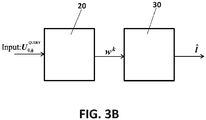
- the outputs of UTIS 20 act as input for an aggregation module 30, as shown for example in Figure 3B , which analyzes every outcome and returns a final prediction l ⁇ of the whole system.
- the underwater tag identifying system (UTIS) 20 and the aggregation module 30 may be comprised in a signal processing module (SPM).
- system 20 has two modules.
- a first module is an object recognition module (ORM) 21 and a second module is a pattern recognition module (PRM) 22.
- the received echo U ⁇ , ⁇ acts as input for the object recognition module 21.
- the object recognition module 21 analyzes the received echo U ⁇ , ⁇ to verify whether the received reflection has collided with an underwater object. In other words, the goal of the object recognition module 21 is to detect the presence of submerged objects.
- the object recognition module 21 uses an energy detector device (EDD) 215, preferably embedded into the system.
- the energy detector device (EDD) 215 is out of the scope of the present invention.
- the energy detector device 215 is a functionality that may be embedded in sonar 2 or may be implemented outside the sonar. Therefore, at the object recognition module 21 it is first established whether an object (buoy) has been recognized or not (output "Yes” or output "No” at the object recognition module 21 in Figure 3 ). When an object has been recognized, an estimated position p ⁇ of the object is provided, as shown in Figure 3A , calculated from the information obtained at the energy detector device (EDD) 215.
- EDD energy detector device
- the object recognition module 21 uses an energy detector device (EDD) 215, the object recognition module 21 generates the following outputs: (1) When neither an object nor a tag have been identified in the received echo U QUERY ⁇ , ⁇ , the object recognition module 21 generates a FALSE message. In this case the analysis ends at this stage, and the output "No" according to this situation is delivered. (2) When the object recognition module 21 detects the presence of an underwater object, the object recognition module 21 generates a TRUE output. In this case (Yes output at block 21), the detected echo U QUERY ⁇ , ⁇ is forwarded to the pattern recognition module 22 for its identification.
- EDD energy detector device
- a set of neighbor echoes u ⁇ , ⁇ associated to the detected echo U QUERY ⁇ , ⁇ is also forwarded to the pattern recognition module 22 for their joint identification.
- the set of neighbor echoes represents a set of angularly adjoining pulse excitation angles. This is shown in Figure 4 , not yet described, in which each neighbor echo is identified with superscript i, wherein 1 ⁇ i ⁇ K. In Figure 3A only one beam is shown.
- the energy detector device 215 is usually controlled by a threshold ⁇ that indicates the minimum signal to background noise ratio required to decide that an object has been detected. Many different numerical computations can be followed to estimate the optimal value of this threshold given an operational scenario and related characteristics. As a matter of example, the Constant False alarm rate may be used. Besides, a rough estimation p ⁇ of the position of the object can be provided. Non-limiting techniques of performing this estimation are detecting the peak of the echo signal U QUERY ⁇ , ⁇ , or using a matched filter for detecting the time instant at which the crossed-correlation is maximum, among others.
- the object recognition module 21 when the object recognition module 21 receives the detection of an object, it analyzes if this object can be identified as a tag, or if, on the contrary, it corresponds to an unidentified object. In this case, "no tag" is returned as output.
- the system has a database of known tags; therefore, it tries to relate all the echoes (or the only echo, as in Figures 3A and 3B ) it receives with some of the tags stored in the database.
- the main objective of the pattern recognition module 22 is to classify the object as a tag type and to estimate the position of the detected object.
- a time-series pattern-recognition process is run in order to predict the type of object.
- the time-series pattern-recognition process is based on a measure of similarity between time series.
- the proposed time-series pattern-recognition process is based on an elastic measure of similarity between time series to prevent the time shift (time delay) between echo responses from affecting the comparison of two time series. That is, in preferred embodiments, the comparison between the received signal and the signature database (tag database) does not depend on the time delay of the received echo.
- the pattern recognition module 22 may use an Elastic Similarity based Nearest Neighbor (ES-NN) classifier. A possible embodiment of an ES-NN is described next.
- ES-NN Elastic Similarity based Nearest Neighbor
- the pattern recognition module 22 uses Elastic Similarity Measures (ESMs) to compute the above measure of similarity between time series (patterns).
- Elastic Similarity Measures that may be used are Dynamic Time Warping (DTW), On-line Dynamic Time Warping (ODTW) and Edit-based measures of similarity.
- DTW Dynamic Time Warping
- ODTW On-line Dynamic Time Warping
- Edit-based measures of similarity Depending on the ESM used, the time axis may shrink or stretch to find the best alignment between time series. This allows the tag identification process to perform more accurately by preventing the similarity computation from effects of the object depth (represented as lags in time domain) or nonlinear distortions in the water medium, such as amplitude warps, on the received signal(s).
- a K-sized set of neighboring beams or set of associated echo beams is received by the sonar, as shown in Figure 4 .
- the neighboring echoes or neighboring beams received by the sonar are referred to as U 1 ⁇ , ⁇ , ... U K ⁇ , ⁇ .
- Each echo or beam is the input of a different underwater tag identifying system (UTIS) 20-0, 20-1, ..., 20-K.
- UTIS underwater tag identifying system
- all inputs (echoes or beams) U QUERY ⁇ , ⁇ U 1 ⁇ , ⁇ , ... U K ⁇ , ⁇ may be processed in a single UTIS 20.
- each system 20-0, 20-1, ..., 20-K delivers a corresponding output w QUERY , w 1 , ..., w K .
- All these outputs are introduced in an aggregation module 30, which is in charge of jointly processing the decision made for every beam in u QUERY ⁇ , ⁇ and provide the user with a final decision on the eventually detected underwater object.
- the final decision is for example a predicted tag type l ⁇ .
- each underwater tag identifying system 20-0, 20-1, ..., 20-K respectively receives the query echo U QUERY ⁇ , ⁇ and its neighboring dataset u QUERY ⁇ , ⁇ as inputs
- w ⁇ QUERY takes value 1 if the energy detector device (EDD) 215 declares no object as per the information in the received signal, and 0 otherwise.
- EDD energy detector device
- the aggregation block 30 in Figure 4 processes the obtained likelihoods to produce an overall class-wide statistic from which to take a decision. This may be done in several ways.
- a more reliable fusion could be achieved in the statistical independence assumption was overridden by e.g. estimating the conditional relationship between w m k and w m k ⁇ for any (k, k') ⁇ ⁇ 1, ..., K ⁇ x ⁇ 1, ..., K ⁇ . This could be done, for instance, by adjusting a parametric distribution to a historical trace of value pairs, such that once fitted, the statistical distribution can be queried to perform a more refined estimation of the aggregated statistic in (5).
Landscapes
- Engineering & Computer Science (AREA)
- Physics & Mathematics (AREA)
- Radar, Positioning & Navigation (AREA)
- Remote Sensing (AREA)
- Computer Networks & Wireless Communication (AREA)
- General Physics & Mathematics (AREA)
- Acoustics & Sound (AREA)
- Measurement Of Velocity Or Position Using Acoustic Or Ultrasonic Waves (AREA)
Abstract
Description
- The present invention relates to the field of detection and identification of objects using Sound Navigation and Ranging technology.
- Sound Navigation and Ranging (sonar) is a technique based on sound propagation. Sonar is used for navigation, communications and detection of objects, such as underwater objects. In particular, sonar is often used for acoustically locating objects of interest in the water. Typically, a sonar, for example equipped in a ship or vessel, emits acoustic signals, in particular acoustic pulses -also referred to as pings- at a fixed frequency f that are propagated through the medium -in this case, water- until they collide with a nearby object, also referred to as target. After collision the emitted signals bounce back to the sonar receiver. By analyzing the received reflections, the existence of underwater objects within a certain distance can be detected. An apparatus and method for underwater detection of objects of interest using sound waves are for example disclosed in
US9213099B1 - A need for classifying water objects has also been identified. For example,
WO2015185032 discloses a method for classifying a water object into a specific vehicle category based on a previously determined parameter rate. Exemplary vehicle categories given inWO2015185032 are: a first category formed by fish trawlers or small motorized vessels; a second one formed by submarines, autonomous underwater vehicles (AUVs) and remotely operated vehicles (ROVs); and a third one formed by large container ships. Categories may be established according to speed, size or applications criteria. A water object is assigned to a water object class by means of a comparison, a correlation or other comparative functions. - Therefore, there is a need to develop an improved method and system for identifying underwater objects.
- The computer-implemented method and system for detecting and identifying underwater objects described in the present invention intends to solve the shortcomings of prior-art methods and systems therefor.
- The method of the present disclosure performs underwater tag (UT) identification by using weighted ensembles of time-series classifiers. The method is implemented in a vessel or ship, such as a medium-sized ship, equipped with a sonar, whose records are used in the underwater tag classification. In the context of the present invention, a tag -also referred to as a label- is a buoy whose response to the echo of a sonar is well-known a priori. Having different tags permits to create a database with different types of buoys (tags) and their corresponding amplitude response to the echo. The presence of an object (buoy) is detected when there is a representative response to an echo. If the response to the echo is similar to one of the responses stored in the tag data base, then the object will be classified as a tag of the type having the similar response. If, on the contrary, the response to the echo is not similar to any one of the responses stored in the tag data base, then the object will be considered as "no tag" which, in the context of the present invention, is interpreted as if nothing (no object) has been detected. In other words, a tag identifies a type of object (a type of buoy). The sonar has one or more transmitters and one or more receivers. The goal is obtain one response per angular pulse. This may be obtained with one or more transmitters and one or more receivers. The sonar emits acoustic pulses -pings- at a certain frequency f. The pulses are propagated through the water until they collide with a nearby object or target. The pulses bounce back to the sonar receiver, where they are recorded for a posterior analysis. Depending on several factors, such as the geometry, composition, position and/or depth of the target, the received reflections -also referred to as echoes-, vary in terms of shape and wave frequency. Thus, the existence of underwater objects within a certain distance can be detected. Although the characteristics of the detected objects are unknown, an analysis of the received echo performed by a time-series based classifier enables to obtain the position and the type of previously known underwater tags.
- A first aspect of the invention relates to a computer-implemented method for detecting and identifying underwater objects, comprising: emitting by a sonar device located in a vessel at least one acoustic signal; receiving by the sonar device at least one echo signal; determining if an underwater object has been detected by verifying whether or not the at least one received echo signal is the consequence of a collision of the at least one acoustic signal with an underwater object; and if no underwater object has been identified, the analysis is ended; if the presence of an underwater object is detected: applying a time-series pattern recognition process to said at least one received echo signal; delivering a set of numerical outputs


- In embodiments of the invention, the step of determining if an object has been detected is done by comparing the signal to background noise ratio of the at least one echo signal with a threshold indicating a minimum signal to background noise ratio required to decide that an object has been detected.
- In embodiments of the invention, the step of determining if an object has been detected further includes estimating the position of the object.
- In embodiments of the invention, in order to predict the tag type of the detected underwater object, and therefore identify the detected object, an Elastic Similarity based Nearest Neighbor (ES-NN) classifier is used, the classifier comprising a knowledge database having a set


 ; normalizing the computed distances by


 as
as

- In embodiments of the invention, together with the at least one echo signal, a K-sized set of neighboring echo beams is received by the sonar, the method further comprising: delivering a set of numerical outputs


- The jointly processing may be done as follows: calculating a weight value βm ∀m ∈ {1, ..., M, Ø} as follows:


- The result returned as output l̂ may be calculated as follows: l̂ =

- In embodiments of the invention, the object is a buoy.
- A second aspect of the invention relates to a system for detecting and identifying underwater objects. The system comprises a sonar device located in a vessel for emitting at least one acoustic signal and receiving at least one echo signal. The system also comprises at least one underwater tag identifying system comprising processing means for: determining if an underwater object has been detected by verifying whether or not the at least one received echo signal is the consequence of a collision of the at least one acoustic signal with an underwater object; and if the presence of an underwater object is detected, determining the type of detected object by: applying a time-series pattern recognition process to said at least one received echo signal, and delivering a set of numerical outputs


- In embodiments of the invention, the at least one underwater tag identifying system comprises: an object recognition module for determining if an underwater object has been detected; and a pattern recognition module for determining the type of detected object.
- In embodiments of the invention, the at least one underwater tag identifying system is further configured to: receive, together with the at least one echo signal, a K-sized set of neighboring echo beams; deliver a set of numerical outputs


- A third aspect of the invention relates to a computer program product comprising computer program instructions/code for performing the method of the first aspect of the invention.
- A fourth aspect of the invention relates to a computer-readable memory/medium that stores program instructions/code for performing the method of the first aspect of the invention.
- Additional advantages and features of the invention will become apparent from the detail description that follows and will be particularly pointed out in the appended claims.
- To complete the description and in order to provide for a better understanding of the invention, a set of drawings is provided. Said drawings form an integral part of the description and illustrate an embodiment of the invention, which should not be interpreted as restricting the scope of the invention, but just as an example of how the invention can be carried out. The drawings comprise the following figures:
-
Figure 1 shows a medium-sized ship equipped with a sonar, emitting pulses and receiving the corresponding echoes, according to an embodiment of the present invention. -
Figure 2 shows a schematic diagram of an underwater tag identifying system (UTIS) according to an embodiment of the present invention. -
Figure 3A shows in more detail the schematic diagram of an underwater tag identifying system (UTIS) ofFigure 2 . -
Figure 3B shows a block diagram of a signal processing module including the underwater tag identifying system (UTIS) ofFigures 2 or3A , and an aggregation module. -
Figure 4 shows a schematic diagram of the inputs and outputs of a signal processing module of an underwater tag identifying system according to an embodiment of the present invention. The signal processing module comprises an underwater tag identifying system (UTIS) and an aggregation module. -
Figure 1 shows a medium-sized ship 1 (in general, vessel) located offshore. Theship 1 is equipped with asonar 2, such as a monostatic and active sonar. Thesonar 2 is used to detect and identify underwater objects, also referred to as targets. Non-limiting examples of possible underwater objects to be detected and identified are objects used for tracking underwater assets, such as underwater cables, underwater probes, offshore oil & gas stations and offshore renewable platforms; or objects used for any other underwater application, such as fishing, underwater speleology or any other underwater activity. These objects are typically associated to a buoy, which is located in the vicinity thereof. Therefore, in the context of the present invention, the objects to be detected and identified are buoys. Thesonar 2 emits acoustic pulses orpings 3 at a certain frequency.Pulses 3 propagate through the water until they collide with an object ortarget 4. Thepulses 3 bounce back as echo signals 5 and are received by thesonar 2. InFigure 1 , theobject 4 is a bouy. The diameter, material and internal composition of a buoy provides a precise response (echo) to a received pulse. The method of the present invention is capable of discriminating this response and therefore determining the type of detected object (buoy). In other words, when the sonar detects an object 4 (because it has received an echo), the method analyzes if the detectedobject 4 corresponds to a well-known tag or not. - The method performs correctly at depths of several tens of meters, such as up to 120-140 m. The detected buoys may have a minimum diameter of several centimeters (10-3 meters), such as a minimum diameter of 2 cm, or of 5 cm, or of 10 cm. The detected buoys may have a maximum diameter of tens of centimeters, such as 40 cm, or 50, or 70 cm, or 100 cm. Buoys may be made of different materials or combinations of materials. They may comprise, for example, aluminium, composite plastics, or others.
-
Figure 2 shows a block diagram of an underwater tag identifying system (UTIS) 20 according to an embodiment of the present invention.System 20 receives and recognizes eachecho signal 5 captured by the receiver of thesonar 2.System 20 may be located in theship 1 or off theship 1, for example on land or in another ship, such as a larger ship. Data received by thesonar 2, that is to say, echo signals 5 to be analyzed bysystem 20, may be provided to thesystem 20 either through a wired interface, for example whensystem 20 is located in theship 1, or through a wireless interface, for example whensystem 20 is off theship 1.System 20 is implemented in processing means, wherein the method for detecting and identifying objects is executed. Processing means may be implemented as one or more processors for example housed in a computing device, such as a server. The at least one processor may comprise a central processing unit which may have programmable hardware/electronics, such as, but without limitation, a field programmable integrated circuit such as an FPGA (i.e. field-programmable gate array), thus configured to run a real-time operating system which manages the field-programmable integrated circuit. In order to execute the proposed method for detecting and identifying objects, data storage means, such as a memory, is also required, in order to store the algorithm(s) for objects detection and identification to be executed and data associated to the executions. Data storage means are preferably housed in the computing device housing the processing means. Data storage means are preferably non-volatile memory means, such as a hard disk drive (HDD) or a solid-state drive (SSD). Data storage means may store computer program products to be executed and data, such as a tag data base comprising a collection of different types of buoys (tags) and their corresponding amplitude response to an echo, echoes received by the sonar and the results of the execution of the proposed method. - Objects to be detected and identified, such as
buoy 4 inFigure 1 , can be represented as labels or tags. Let {I1, ..., Im, ..., IM} be a set of labels or tags, wherein each of the elements, Im, represents a tag with a known geometry and composition (e.g. material of group of materials). The geometry and composition of each tag, along with its position and depth, imprint varying perturbations in time and amplitude onto theecho signal 5 received by thesonar 2, in such a way that each tag has its own echo signature that may help distinguishing the specific tag model detected by thesonar 2. For example, depending on their construction, two different tags may result in a different form of pulse response in terms of the number of significant amplitude maxima and their temporal separation. The proposed method and system enables the joint detection and model identification of underwater tags through the analysis of receivedechoes 5, more particularly, through a time-series pattern recognition process. - In
Figure 2 , an underwater tag identifying system (UTIS) for detecting and identifying underwater objects through the analysis of the received echoes 5, is shown. The underwater tag identifying system (UTIS) 20 processes anecho 5 received bysonar 2 and delivers an estimation of the target detected by theecho 5, that is to say, the estimated likelihood that a beam sent in certain direction corresponds to certain tag. In the underwater tag identifying system (UTIS) 20 ofFigure 2 , Uθ,φ represents a single echo received in the direction of θ and φ polar and azimuthal coordinates with respect to the sonar receiver when an emitted pulse orping 3 collides with anobject 4. More specifically, Uθ,φ is a time series composed by different samples

- Therefore, UQUERY θ,φ denotes the amplitude of the reflected signal received as a result of the emitted
ping 3, which is read bysystem 20 for its analysis. The position of theobject 4 in spherical coordinates, i.e., depth, polar and azimuthal angles with respect to thesonar 2, is represented as p = (ro, θο, φo). The position of the detectedobject 4 is unknown to thesonar 2. - In general,
system 20 is applied separately to each echo UQUERY θ,φ in a an echo set u θ,Φ received bysonar 2, which is a conventional sonar and is out of the scope of the present invention. By this notation θ (respectively,Φ) denotes a set of θ (correspondingly φ) neighboring values as per the scanning schedule set in the radar device (sonar 2). The set of neighboring values are echoes - responses - to pulses emitted in neighboring angular directions, i.e. response to excitation at an angle of 35° and 36°, for example. Sonar beams sent along these directions are prone to impacting on the same object should this exist. Therefore, better classification accuracy can be expected if decisions taken for each echo are fused together under a certain aggregation approach (neighboring beams). This notation also accommodates any other source of coherent redundancy for the classification (e.g. repeated beams sent in the same (θ, φ) direction over time), just by extending the notation as e.g. u θ,Φ,┌, where ┌ is the set of different absolute times at which beams were sent in the same direction. - It is assumed that the number of neighboring beams (i.e. the cardinality of u θ,Φ) is given by K, such that for each received echo Uθ,Φ, the
system 20 delivers a set of numerical outputs W = {wk}K k=1 with

aggregation module 30, as shown for example inFigure 3B , which analyzes every outcome and returns a final prediction l̂ of the whole system. The underwater tag identifying system (UTIS) 20 and theaggregation module 30 may be comprised in a signal processing module (SPM). - Referring now to
Figure 3A , which represents in more detail the underwater tag identifying system (UTIS) 20 ofFigure 2 , in which a single echo is represented,system 20 has two modules. A first module is an object recognition module (ORM) 21 and a second module is a pattern recognition module (PRM) 22. The received echo Uθ,φ acts as input for theobject recognition module 21. Theobject recognition module 21 analyzes the received echo Uθ,φ to verify whether the received reflection has collided with an underwater object. In other words, the goal of theobject recognition module 21 is to detect the presence of submerged objects. To this end, theobject recognition module 21 uses an energy detector device (EDD) 215, preferably embedded into the system. The energy detector device (EDD) 215 is out of the scope of the present invention. Theenergy detector device 215 is a functionality that may be embedded insonar 2 or may be implemented outside the sonar. Therefore, at theobject recognition module 21 it is first established whether an object (buoy) has been recognized or not (output "Yes" or output "No" at theobject recognition module 21 inFigure 3 ). When an object has been recognized, an estimated position p̂ of the object is provided, as shown inFigure 3A , calculated from the information obtained at the energy detector device (EDD) 215. - That is to say, using an energy detector device (EDD) 215, the
object recognition module 21 generates the following outputs: (1) When neither an object nor a tag have been identified in the received echo UQUERY θ,φ, theobject recognition module 21 generates a FALSE message. In this case the analysis ends at this stage, and the output "No" according to this situation is delivered. (2) When theobject recognition module 21 detects the presence of an underwater object, theobject recognition module 21 generates a TRUE output. In this case (Yes output at block 21), the detected echo UQUERY θ,φ is forwarded to thepattern recognition module 22 for its identification. It is remarked that, in preferred embodiments, together with the detected echo UQUERY θ,φ, a set of neighbor echoes u θ,Φ associated to the detected echo UQUERY θ,φ is also forwarded to thepattern recognition module 22 for their joint identification. The set of neighbor echoes represents a set of angularly adjoining pulse excitation angles. This is shown inFigure 4 , not yet described, in which each neighbor echo is identified with superscript i, wherein 1 ≤ i ≤ K. InFigure 3A only one beam is shown. When no object is recognized by the sonar - by object recognition module 21-, or an object which is not a tag is detected, (output "No" in block 21), wk = {0, ..., 0, ..., 1}, wherein wØ =1, which means "no tag". And when an object is recognized by the object recognition module 21 (output "Yes" in block 21),
- The
energy detector device 215 is usually controlled by a threshold γ that indicates the minimum signal to background noise ratio required to decide that an object has been detected. Many different numerical computations can be followed to estimate the optimal value of this threshold given an operational scenario and related characteristics. As a matter of example, the Constant False alarm rate may be used. Besides, a rough estimation p̂ of the position of the object can be provided. Non-limiting techniques of performing this estimation are detecting the peak of the echo signal UQUERY θ,φ, or using a matched filter for detecting the time instant at which the crossed-correlation is maximum, among others. - In other words, when the
object recognition module 21 receives the detection of an object, it analyzes if this object can be identified as a tag, or if, on the contrary, it corresponds to an unidentified object. In this case, "no tag" is returned as output. The system has a database of known tags; therefore, it tries to relate all the echoes (or the only echo, as inFigures 3A and3B ) it receives with some of the tags stored in the database. Once theenergy detector device 215 has informed about the existence of an object underwater, the main objective of thepattern recognition module 22 is to classify the object as a tag type and to estimate the position of the detected object. When an object has been recognized, at the pattern recognition module 22 a time-series pattern-recognition process is run in order to predict the type of object. The time-series pattern-recognition process is based on a measure of similarity between time series. In preferred embodiments, the proposed time-series pattern-recognition process is based on an elastic measure of similarity between time series to prevent the time shift (time delay) between echo responses from affecting the comparison of two time series. That is, in preferred embodiments, the comparison between the received signal and the signature database (tag database) does not depend on the time delay of the received echo. - The discriminability of objects depends on the richness of the annotated time series database utilized in the
pattern recognition module 22. Referring back to outputs


object recognition module 21 returns a NULL value, or if thepattern recognition module 22 has detected an object that does not correspond to a known tag. In any other case
value 0. This is explained later with reference toFigure 4 , where the M+1 elements in wk relate to the single echo Uθ,φ and its spatially surrounding echoes. - Next it is explained how

pattern recognition module 22 for the fulfillment of the following statement: the analyzed echo has detected an object and this object is tag Im. In order to predict the tag type under which a detected object is classified, thepattern recognition module 22 may use an Elastic Similarity based Nearest Neighbor (ES-NN) classifier. A possible embodiment of an ES-NN is described next. - Let


pattern recognition module 22 uses a 1-Nearest Neighbor classifier that works as follows:
First, vector of distances
 . At this point, in embodiments of the invention only an echo for a (θ, φ) combination is processed. In this case, a performance boost of the overall system is achieved by aggregating decisions.
- Then, the computed distances are normalized by

sum 1. Then, an approximation of the likelihood under which UQUERY θ,φ can be thought to be an echo bounced back by reflecting on a tag model m, is rendered. This yields an approximation for the conditional probability

- Next, the label l̂ of the most similar signature to the echo in the setis assigned, i.e.


energy detector device 215. - In order to measure the similarity among query and reference signatures, in this embodiment the
pattern recognition module 22 uses Elastic Similarity Measures (ESMs) to compute the above measure of similarity between time series (patterns). Non-limiting examples of Elastic Similarity Measures that may be used are Dynamic Time Warping (DTW), On-line Dynamic Time Warping (ODTW) and Edit-based measures of similarity. Depending on the ESM used, the time axis may shrink or stretch to find the best alignment between time series. This allows the tag identification process to perform more accurately by preventing the similarity computation from effects of the object depth (represented as lags in time domain) or nonlinear distortions in the water medium, such as amplitude warps, on the received signal(s). - It is now considered that, associated to the query echo UQUERY θ,φ, a K-sized set of neighboring beams or set of associated echo beams

Figure 4 . InFigure 4 , the neighboring echoes or neighboring beams received by the sonar are referred to as U1 θ,φ, ... UK θ,φ. Each echo or beam is the input of a different underwater tag identifying system (UTIS) 20-0, 20-1, ..., 20-K. It is remarked that, in an alternative embodiment, all inputs (echoes or beams) UQUERY θ,φ U1 θ,φ, ... UK θ,φ may be processed in asingle UTIS 20. In this case, multiplexing means are required in order to process each beam one by one; and already processed outputs wQUERY, w1, ..., wK should be stored until of the them are obtained. InFigure 4 , each system 20-0, 20-1, ..., 20-K delivers a corresponding output wQUERY, w1, ..., wK. All these outputs are introduced in anaggregation module 30, which is in charge of jointly processing the decision made for every beam in u QUERY θ,Φ and provide the user with a final decision on the eventually detected underwater object. The final decision is for example a predicted tag type l̂. This is done as follows:
Once each underwater tag identifying system 20-0, 20-1, ..., 20-K respectively receives the query echo UQUERY θ,φ and its neighboring dataset u QUERY θ,Φ as inputs, each system 20-0, 20-1, ..., 20-K computes the conditional likelihoods:


value 1 if the energy detector device (EDD) 215 declares no object as per the information in the received signal, and 0 otherwise. The same criterion holds for the neighboring beams in u QUERY θ,Φ (correspondingly,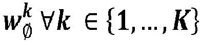
aggregation block 30 inFigure 4 processes the obtained likelihoods to produce an overall class-wide statistic from which to take a decision. This may be done in several ways. - In a particular embodiment, a straightforward approach is used, in which a weighted majority is performed by voting among the decisions made locally based on wQUERY and {wk}K k=1. Matematically:


- Other aggregation approaches may be used alternatively. For instance, a more reliable fusion could be achieved in the statistical independence assumption was overridden by e.g. estimating the conditional relationship between


- It has therefore been explained how underwater objects are detected by a sonar and, although the characteristics of the detected objects are unknown, an analysis of the received echo performed by a time-series based classifier enables to obtain the position and the type of the detected object.
- The invention is obviously not limited to the specific embodiment(s) described herein, but also encompasses any variations that may be considered by any person skilled in the art (for example, as regards the choice of materials, dimensions, components, configuration, etc.), within the general scope of the invention as defined in the claims.
Claims (14)
- A computer-implemented method for detecting and identifying underwater objects, comprising:emitting by a sonar device (2) located in a vessel (1) at least one acoustic signal (3);receiving by the sonar device (2) at least one echo signal (UQUERY θ,φ);determining if an underwater object (4) has been detected by verifying whether or not the at least one received echo signal (UQUERY θ,φ) is the consequence of a collision of the at least one acoustic signal (3) with an underwater object (4), andif no underwater object (4) has been identified, the analysis is ended;if the presence of an underwater object (4) is detected:applying a time-series pattern recognition process to said at least one received echo signal (UQUERY θ,φ);delivering a set of numerical outputs

 predicting from the set of numerical outputs wk the tag type (l̂) of the detected underwater object (4).
 - The method of claim 1, wherein the step of determining if an object (4) has been detected is done by comparing the signal to background noise ratio of the at least one echo signal (UQUERY θ,φ) with a threshold indicating a minimum signal to background noise ratio required to decide that an object (4) has been detected.
- The method of any one of the preceding claims, wherein the step of determining if an object (4) has been detected further includes estimating the position (p̂) of the object (4).
- The method of any one of the preceding claims, wherein in order to predict the tag type (l̂) of the detected underwater object (4), and therefore identify the detected object (4), an Elastic Similarity based Nearest Neighbor (ES-NN) classifier is used, the classifier comprising a knowledge database having a set


- The method of claim 4, wherein in order to predict the label of a query echo signal (UQUERY θ,φ), the method performs the following steps:computing a vector of distances

 ;
; normalizing the computed distances by
 obtaining an approximation for the conditional probability
 assigning the label l̂ of the most similar signature to the echo in the setas l̂ =

- The method of any one of the preceding claims, wherein together with the at least one echo signal (UQUERY θ,φ), a K-sized set of neighboring echo beams (U1 θ,φ, ... UK θ,φ) is received by the sonar (2), the method further comprising:delivering a set of numerical outputs

 for each of the K neighboring echo beams (U1 θ,φ, ... UK θ,φ), delivering a set of numerical outputs
 jointly processing the K+1 sets of numerical outputs wQUERY, w1, ... wK, for predicting the tag type (l̂) of the detected underwater object (4).
 - The method of claim 6, wherein said jointly processing is done as follows:calculating a weight value βm ∀m ∈ {1, ..., M, Ø} as follows:
 wherein
 providing a result as output l̂, being the tag that features a higher probability as per the evidence contained in the received signal set.
 - The method of claim 7, wherein the result returned as output l̂ is calculated as follows:

- The method of any one of the preceding claims, wherein said object (4) is a buoy.
- A system for detecting and identifying underwater objects, comprising:a sonar device (2) located in a vessel (1) for emitting at least one acoustic signal (3) and receiving at least one echo signal (UQUERY θ,φ);at least one underwater tag identifying system (20; 20-0, 20-1, ..., 20-K) comprising processing means for: determining if an underwater object (4) has been detected by verifying whether or not the at least one received echo signal (UQUERY θ,φ) is the consequence of a collision of the at least one acoustic signal (3) with an underwater object (4); and if the presence of an underwater object (4) is detected, determining the type of detected object by:applying a time-series pattern recognition process to said at least one received echo signal (UQUERY θ,φ), anddelivering a set of numerical outputs

 a module (30) for predicting from the set of numerical outputs wk the tag type (l̂) of the detected underwater object (4).
 - The system of claim 10, wherein the at least one underwater tag identifying system (20; 20-0, 20-1, ..., 20-K) comprises:an object recognition module (21) for determining if an underwater object (4) has been detected;a pattern recognition module (22) for determining the type of detected object.
- The system of either claim 10 or 11, wherein the at least one underwater tag identifying system (20; 20-0, 20-1, ..., 20-K) is further configured to:receive, together with the at least one echo signal (UQUERY θ,φ), a K-sized set of neighboring echo beams (U1 θ,φ, ... UK θ,φ),deliver a set of numerical outputs

 for each of the K neighboring echo beams (U1 θ,φ, ... UK θ,φ), deliver set of numerical outputs
 jointly process the K+1 sets of numerical outputs wQUERY, w1, ... wK, for predicting the tag type (l̂) of the detected underwater object (4).
 - A computer program product comprising computer program instructions/code for performing the method according to any one of claims 1-9.
- A computer-readable memory/medium that stores program instructions/code for performing the method according to any one of claims 1-9.
Priority Applications (2)
| Application Number | Priority Date | Filing Date | Title |
|---|---|---|---|
| EP19382961.1A EP3816664A1 (en) | 2019-11-04 | 2019-11-04 | Method, system and computer program product for identifying underwater objects |
| PCT/EP2020/080942 WO2021089610A1 (en) | 2019-11-04 | 2020-11-04 | Method, system and computer program product for identifying underwater objects |
Applications Claiming Priority (1)
| Application Number | Priority Date | Filing Date | Title |
|---|---|---|---|
| EP19382961.1A EP3816664A1 (en) | 2019-11-04 | 2019-11-04 | Method, system and computer program product for identifying underwater objects |
Publications (1)
| Publication Number | Publication Date |
|---|---|
| EP3816664A1 true EP3816664A1 (en) | 2021-05-05 |
Family
ID=68503042
Family Applications (1)
| Application Number | Title | Priority Date | Filing Date |
|---|---|---|---|
| EP19382961.1A Withdrawn EP3816664A1 (en) | 2019-11-04 | 2019-11-04 | Method, system and computer program product for identifying underwater objects |
Country Status (2)
| Country | Link |
|---|---|
| EP (1) | EP3816664A1 (en) |
| WO (1) | WO2021089610A1 (en) |
Cited By (1)
| Publication number | Priority date | Publication date | Assignee | Title |
|---|---|---|---|---|
| TWI905582B (en) * | 2023-11-30 | 2025-11-21 | 財團法人金屬工業研究發展中心 | Underwater object removal system |
Citations (2)
| Publication number | Priority date | Publication date | Assignee | Title |
|---|---|---|---|---|
| WO2015185032A1 (en) | 2014-06-05 | 2015-12-10 | Atlas Elektronik Gmbh | Method for classifying a water object, device, sonar, and water vehicle or stationary platform |
| US9213099B1 (en) | 2013-02-25 | 2015-12-15 | The Boeing Company | Sonar-based underwater target detection system |
-
2019
- 2019-11-04 EP EP19382961.1A patent/EP3816664A1/en not_active Withdrawn
-
2020
- 2020-11-04 WO PCT/EP2020/080942 patent/WO2021089610A1/en not_active Ceased
Patent Citations (2)
| Publication number | Priority date | Publication date | Assignee | Title |
|---|---|---|---|---|
| US9213099B1 (en) | 2013-02-25 | 2015-12-15 | The Boeing Company | Sonar-based underwater target detection system |
| WO2015185032A1 (en) | 2014-06-05 | 2015-12-10 | Atlas Elektronik Gmbh | Method for classifying a water object, device, sonar, and water vehicle or stationary platform |
Non-Patent Citations (3)
| Title |
|---|
| LINES JASON ET AL: "Time series classification with ensembles of elastic distance measures", JOURNAL OF DATA MINING AND KNOWLEDGE DISCOVERY, NORWELL, MA, US, vol. 29, no. 3, 28 June 2014 (2014-06-28), pages 565 - 592, XP035479565, ISSN: 1384-5810, [retrieved on 20140628], DOI: 10.1007/S10618-014-0361-2 * |
| MATHEUS DOS SANTOS ET AL: "Object Classification in Semi Structured Enviroment Using Forward-Looking Sonar", SENSORS, vol. 17, no. 10, 29 September 2017 (2017-09-29), pages 2235, XP055692656, DOI: 10.3390/s17102235 * |
| ROBERT THOMAS OLSZEWSKI: "Generalized feature extraction for structural pattern recognition in time-series data", 1 February 2001 (2001-02-01), Pittsburgh, PA 15213, XP055693100, ISBN: 978-0-493-53871-6, Retrieved from the Internet <URL:https://www.cs.cmu.edu/~bobski/pubs/tr01108-twosided.pdf> [retrieved on 20200508] * |
Cited By (1)
| Publication number | Priority date | Publication date | Assignee | Title |
|---|---|---|---|---|
| TWI905582B (en) * | 2023-11-30 | 2025-11-21 | 財團法人金屬工業研究發展中心 | Underwater object removal system |
Also Published As
| Publication number | Publication date |
|---|---|
| WO2021089610A1 (en) | 2021-05-14 |
Similar Documents
| Publication | Publication Date | Title |
|---|---|---|
| JP3573783B2 (en) | Sonar system | |
| Kim et al. | Imaging sonar based real-time underwater object detection utilizing AdaBoost method | |
| Beard et al. | Sensor control for multi-target tracking using Cauchy-Schwarz divergence | |
| US12080060B2 (en) | Method and system for indoor multipath ghosts recognition | |
| US11280899B2 (en) | Target recognition from SAR data using range profiles and a long short-term memory (LSTM) network | |
| Wrabel et al. | A survey of artificial intelligence approaches for target surveillance with radar sensors | |
| Villar et al. | Evaluation of an efficient approach for target tracking from acoustic imagery for the perception system of an autonomous underwater vehicle | |
| CN115061113B (en) | Target detection model training method and device for radar and storage medium | |
| CN119179057B (en) | Unmanned aerial vehicle identification tracking method combined with low-altitude radar AI algorithm | |
| CN113608193A (en) | Radar multi-target distance and speed estimation method based on UNet | |
| CN113933790A (en) | Inversion identification method, device and medium for working mode of phased array radar | |
| CN114740441A (en) | Low-slow small-target radar echo identification method based on small samples | |
| Stinco et al. | Unsupervised active sonar contact classification through anomaly detection | |
| CN117897741A (en) | Method and apparatus for generating synthetic training data for an ultrasound sensor model | |
| Oliveira et al. | Probabilistic positioning of a mooring cable in sonar images for in-situ calibration of marine sensors | |
| Soldi et al. | Underwater tracking based on the sum-product algorithm enhanced by a neural network detections classifier | |
| WO2024062365A1 (en) | Parallax among corresponding echoes | |
| WO2021089610A1 (en) | Method, system and computer program product for identifying underwater objects | |
| CN114545422B (en) | Active sonar target identification method based on multiple physical characteristics | |
| EP4369028A1 (en) | Interface for detection representation of hidden activations in neural networks for automotive radar | |
| Oliveira et al. | Sonar-based cable detection for in-situ calibration of marine sensors | |
| Wout et al. | Transfer learning for distance classification of marine vessels using underwater sound | |
| Wang et al. | Enhancing feature-aided data association tracking in passive sonar arrays: An advanced Siamese network approach | |
| CN113281756A (en) | Underwater obstacle classification and identification method based on collision-prevention sonar | |
| CN115792877B (en) | Ultrasonic Radar Noise Identification Method and System |
Legal Events
| Date | Code | Title | Description |
|---|---|---|---|
| PUAI | Public reference made under article 153(3) epc to a published international application that has entered the european phase |
Free format text: ORIGINAL CODE: 0009012 |
|
| STAA | Information on the status of an ep patent application or granted ep patent |
Free format text: STATUS: THE APPLICATION HAS BEEN PUBLISHED |
|
| AK | Designated contracting states |
Kind code of ref document: A1 Designated state(s): AL AT BE BG CH CY CZ DE DK EE ES FI FR GB GR HR HU IE IS IT LI LT LU LV MC MK MT NL NO PL PT RO RS SE SI SK SM TR |
|
| STAA | Information on the status of an ep patent application or granted ep patent |
Free format text: STATUS: REQUEST FOR EXAMINATION WAS MADE |
|
| 17P | Request for examination filed |
Effective date: 20211104 |
|
| RBV | Designated contracting states (corrected) |
Designated state(s): AL AT BE BG CH CY CZ DE DK EE ES FI FR GB GR HR HU IE IS IT LI LT LU LV MC MK MT NL NO PL PT RO RS SE SI SK SM TR |
|
| STAA | Information on the status of an ep patent application or granted ep patent |
Free format text: STATUS: EXAMINATION IS IN PROGRESS |
|
| 17Q | First examination report despatched |
Effective date: 20231206 |
|
| STAA | Information on the status of an ep patent application or granted ep patent |
Free format text: STATUS: THE APPLICATION IS DEEMED TO BE WITHDRAWN |
|
| 18D | Application deemed to be withdrawn |
Effective date: 20240607 |