EP3816606A1 - Apparatus and method for the analysis of snowpack samples - Google Patents
Apparatus and method for the analysis of snowpack samples Download PDFInfo
- Publication number
- EP3816606A1 EP3816606A1 EP20203625.7A EP20203625A EP3816606A1 EP 3816606 A1 EP3816606 A1 EP 3816606A1 EP 20203625 A EP20203625 A EP 20203625A EP 3816606 A1 EP3816606 A1 EP 3816606A1
- Authority
- EP
- European Patent Office
- Prior art keywords
- snowpack
- sample
- analysis
- sampling element
- carriage
- Prior art date
- Legal status (The legal status is an assumption and is not a legal conclusion. Google has not performed a legal analysis and makes no representation as to the accuracy of the status listed.)
- Granted
Links
Images

Classifications
-
- G—PHYSICS
- G01—MEASURING; TESTING
- G01N—INVESTIGATING OR ANALYSING MATERIALS BY DETERMINING THEIR CHEMICAL OR PHYSICAL PROPERTIES
- G01N3/00—Investigating strength properties of solid materials by application of mechanical stress
- G01N3/08—Investigating strength properties of solid materials by application of mechanical stress by applying steady tensile or compressive forces
-
- G—PHYSICS
- G01—MEASURING; TESTING
- G01N—INVESTIGATING OR ANALYSING MATERIALS BY DETERMINING THEIR CHEMICAL OR PHYSICAL PROPERTIES
- G01N3/00—Investigating strength properties of solid materials by application of mechanical stress
- G01N3/24—Investigating strength properties of solid materials by application of mechanical stress by applying steady shearing forces
-
- G—PHYSICS
- G01—MEASURING; TESTING
- G01N—INVESTIGATING OR ANALYSING MATERIALS BY DETERMINING THEIR CHEMICAL OR PHYSICAL PROPERTIES
- G01N33/00—Investigating or analysing materials by specific methods not covered by groups G01N1/00 - G01N31/00
- G01N33/18—Water
- G01N33/1873—Ice or snow
Definitions
- the present invention relates to a portable apparatus for subjecting snowpack samples to analysis and to a related method for subjecting snowpack samples to analysis.
- the main factors that affect the ability of a vehicle to develop forces of traction on a snowpack are, in fact, the characteristics of the pneumatic tyres which are fitted to the vehicle and the properties of the snowpack.
- a pneumatic tyre With regard to the ability of a pneumatic tyre to generate forces on a snow-covered surface, this depends upon the rubber compound and the structure of the pneumatic tyre, in particular a pneumatic tyre tread (by the dimensions, design and geometrical characteristics of the blocks and of the tread grooves and by the ability thereof to trap layers of snow).
- the contribution due to the characteristics of the snowpack it was verified that this contribution depends primarily upon the shear strength of the volumes of snow trapped within the grooves of the tread.
- the snowpack is formed from the superposition of multiple layers
- each layer is characterized by a content of water (or humidity), by the density thereof and by the presence of snow having specific structures and crystal dimensions.
- the contribution to the forces exerted by the pneumatic tyre depends heavily upon the density of the volumes of snow trapped within the grooves of the tread and, consequently, is linked to the mechanical and morphological characteristics of the layer(s) of snow involved in said volumes.
- the set of characteristics of the different layers of snow and the environmental parameters determines the mechanical properties of each layer; clearly the mechanical properties of each layer are not predictable by means of indirect measurements.
- the aim of the present invention is to provide a portable apparatus for subjecting snowpack samples to analysis that is free from the disadvantages of the state of the art and that is, in particular, easy and inexpensive to implement.
- a further aim of the present invention is to provide a method for subjecting snowpack samples to analysis that is free from the disadvantages of the state of the art and, in particular, that is easy and inexpensive to implement.
- a portable apparatus for the analysis of snowpack samples and a related method for subjecting snowpack samples to analysis, as set out in the appended claims.
- the number 1 indicates in the entirety thereof, a portable apparatus for subjecting snowpack samples C to analysis.
- the device 1 comprises a structure 2 which in turn comprises a fixed guide structure 3 defined by two linear guides 4 that are parallel therebetween and two head elements 6.
- a carriage 5 slides on linear guides 4.
- the two linear guides 4 are connected, at the ends thereof, to the two head elements 6 intended to act as a limit switch for the carriage 5.
- the structure 2 comprises a plate 7 with a parallelepiped shape having a reduced thickness (on the order of 5-10 mm) and presenting a flat upper surface 8 and a flat lower surface 9.
- four appendages 10 are provided for the connection by appropriate fastening means (known and not described in detail) with the two head elements 6.
- the plate 7 is equipped with a through opening 11 formed at a substantially central position and provided with an X-axis.
- the aperture 11 is defined by a cylindrical surface with a diameter of between 20 and 50 mm, preferably between 25 and 35 mm.
- the diameter of the aperture 11 is 30 mm.
- the structure 2 also includes an adapter 12 defined by a parallelepiped shaped plate with a thickness of between 5 and 15 mm. According to a preferred variant, the thickness of the adapter 12 is 10 mm.
- the adapter 12 has a flat upper surface 13 and a flat lower surface 14. The lower surface 14 is arranged in contact with (lies upon) the upper surface 8.
- the adapter 12 is connected, by appropriate fastening means (known and not described in detail) to the plate 7.
- the adapter 12 preferably has, in plan view, dimensions that approximate, by default, the dimensions of the plate 7.
- the adapter 12 is also provided with a through opening 15 formed at a substantially central and coaxial position with respect to the X-axis (and therefore coaxial, in use, to the opening 11).
- the aperture 15 is defined by a cylindrical surface with the same diameter as the opening 11, i.e., a diameter of between 20 and 50 mm, preferably of between 25 and 35 mm. According to a preferred variant, the diameter of the aperture 15 is 30 mm.
- the adapter 12 is provided with two grooves 16 intended to receive a respective lateral rib 17 of a sampling element 18, as better described in the following discussion.
- the two grooves 16 are formed at the opening 15.
- the grooves 16 are formed at diametrically opposite ends (with respect to the X-axis) of the opening 15.
- the grooves 16 are formed at the upper surface 16.
- Each groove 16 is defined by a surface with a substantially flat base which is joined to a back wall (curved or flat) and two side walls, which are also substantially flat.
- the sampling element 18 is intended both to produce the snowpack core sample C to be analyzed and to receive the snowpack sample C during the analysis step.
- the sampling element 18 is made of a plastic or metallic material; the sampling element 18 is preferably obtained by means of 3D molding techniques.
- the sampling element 18 is defined by a tubular body 19 having an inner surface 20 with cylindrical symmetry around an X'-axis.
- the inner surface 20 has a diameter of between 15 and 45 mm; preferably the diameter of the inner surface 20 is between 20 and 30 mm.
- the tubular body 19 is divided into a coring portion 19* and an analysis portion 19** joined together at an outer edge 21.
- the coring portion 19* and the measurement portion 19** have respective substantially uniform extensions along the X'-axis.
- the portions 19* and 19** may be uniform or non-uniform, symmetrical or non-symmetrical, therebetween.
- the coring portion 19* has an extension along the X'-axis of between 15 and 30 mm, preferably equal to 22 mm.
- the dimensions of the coring portion 19* make it possible to isolate samples C of a single layer from the layers that define the snowpack. In this way it is possible, by means of differing samplings, to take samples C of the individual layers of snowpack that are responsible for the performance of the pneumatic tyres on snow and evaluate the shear resistance thereof.
- the analysis portion 19** has an outer surface 22 that is cylindrical and coaxial with respect to the X'-axis.
- the coring portion 19* has instead an outer truncated-cone surface 23 that is coaxial to the X'-axis.
- the outer surface 23 gradually widens towards the analysis portion 19**.
- the cylindrical outer surface 22 therefore has a diameter equal to the larger diameter of the outer truncated-cone surface 23.
- the particular shape of the coring portion 19* makes it possible to penetrate the snowpack, isolate, detach and retain the snowpack sample C within the area defined by the inner surface 20.
- the sampling element 18 carries, and is connected to, the two lateral ribs 17 which extend laterally from the outer surfaces 22, 23.
- the lateral ribs 17 are substantially arranged at the edging 21.
- the lateral ribs 17 are arranged at the extremity therebetween, diametrically opposite (with respect to the X'-axis) the outer surfaces 22, 23.
- the lateral ribs 17 have a shape that is complementary to the shape of the grooves 16.
- each lateral rib 17 is provided with respective opposing bottom surfaces which are arranged, when in use, in abutment on the bottom surface of the respective groove 16, in such a way that the distance between the lower end of the sampling element 18 and the upper end of the carriage 5 is between 0.1 and 3 mm.
- both ends of the lateral ribs 17 have a shape that is complementary to the shape of the grooves 16.
- both the ends of the lateral ribs 17 facing the coring portion 19* and the ends of the lateral ribs 17 facing the analysis portion 19** have complementary shapes to the shape of the grooves 16 and are intended to engage, in use, with the grooves 16.
- the carriage 5 is defined by a box-like body 24 provided with a seat 25 for partially receiving the snowpack sample C of the snowpack and is arranged, in use, below the plate 7. In use, the carriage 5 is housed in such a way that the seat 25 is turned towards and directly facing the plate 7.
- the seat 25 is defined by a circular bottom surface 26 and by a cylindrical lateral surface 27 having a diameter that approximates the diameter of the inner surface 20.
- the seat 25 has a variable height of between 1 mm and 20 mm; preferably, the height of the seat 25 is between 8 and 15 mm.
- the height of the seat 25 is modified (adjusted) by means of the insertion of a number of disc shims (not shown) of suitable height within the seat 25 itself. Underneath, the carriage 5 is connected to four bearings 28 which allow for the sliding of the carriage 5 itself on two rails 3.
- a front end of the carriage 5 is provided with an appendix 5* that protrudes such as to be interposed, when in use, between the two rails 3.
- an appendix 5* that protrudes such as to be interposed, when in use, between the two rails 3.
- a groove which together with the appendix 5* defines a housing that is intended to house a load cell for detecting the shear strength of the snowpack sample C.
- the apparatus 1 may comprise a piezoelectric force sensor or a magnetic force sensor or a hydraulic force sensor.
- the apparatus 1 comprises a compressive member, in particular a piston 29, having a cylindrical body 30 that is intended to slide within the sampling element 18 and an upper handle 31 (or knob).
- cylindrical body 30 is provided with a cylindrical outer surface wherein the diameter thereof approximates, by default, the diameter of the inner surface 20.
- the apparatus comprises an actuating device 32, in particular an electric motor, which is connected to the carriage 5 and that is suitable for sliding the carriage 5 on the rails 3.
- the actuating device 32 is arranged externally to the box-like body 24, within a dedicated housing.
- the actuating device 32 is housed within the box-like body 24.
- a further load cell is provided in order to detect the compression force exerted by the piston 29 upon the snowpack sample C; the further load cell is preferably housed on the piston 29.
- the following describes the method for using the portable apparatus 1 in subjecting to analysis snowpack samples C, as described heretofore.
- the operator proceeds manually to implementing the sampling (coring) of the snowpack sample C for analysis.
- the snowpack sample C is taken in penetrating into the snowpack using the coring portion 19*, such that the snowpack sample C engages with the seat defined, within the coring portion 19* itself, by the inner surface 20.
- the analysis portion 19** is used by the operator to grasp the sampling element 18, whilst the coring portion 19* serves as a core barrel; the outer truncated-cone surface 23 in fact allows for the penetration into the snowpack whilst the inner surface 20 protects and houses the snowpack sample C.
- the sampling step is concluded.
- the sampling element 18 is extracted from the snowpack and inserted into the structure 2, in such a way as to coincide with the X' and X axes.
- the sampling element 18 acts, in this case, as a centering pin.
- the analysis portion 19** or else the coring portion 19* is inserted within the openings 11 and 15.
- the analysis portion 19** is inserted within the openings 11 and 15; in particular, the analysis portion 19** slides inside the openings 11 and 15 until it stops when each lateral rib 17 has engaged with the respective groove 16.
- the analysis portion 19** protrudes (juts out from the plate 7 downwards) such as to partially fill the free space between the plate 7 and the carriage 5.
- the analysis portion 19** (in particular, a bottom surface of the analysis portion 19**) is arranged in the vicinity of a flat upper surface of the carriage 5, but not in contact (i.e., not resting in contact) with the carriage 5.
- the analysis portion 19** and the carriage 5 are separated by a gap (slit or slot) of a few mm, in particular the dimensions of said interstice are between 0.1 and 3 mm.
- the carriage 5 is located below the sampling element 18, such that the seat 25 is coaxial to the openings 11 and 15. In other words, the seat 25 is facing the sampling element 18 such as to partially receive the snowpack sample C.
- the piston 29 is inserted and made to slide, inside the sampling element 18, by an operator.
- the pressure exerted by the operator on the snowpack sample C by means of the piston 29 is detected by means of the further load cell housed on the piston 29.
- the snowpack sample C slides downwards (i.e., towards the carriage 5) until the load, detected by the load cell at the piston head 29, reaches a target compression value, determined at a preliminary stage of the analysis.
- the snowpack sample C is partially housed within the seat 25 and partially housed within the analysis portion 19**.
- the actuating device 32 is driven in order to allow the sliding of the carriage 5 upon the rails 3; the shear strength of the snowpack sample C is detected by means of the load cell.
- the coring portion 19* after the actual coring step, is inserted directly within the openings 11 and 15; in particular, the coring portion 19* slides inside the openings 11 and 15 until it stops when each lateral rib 17 has engaged with the respective groove 16.
- the coring portion 19* protrudes (juts out from the plate 7 downwards) such as to partially fill the free space between the plate 7 and the carriage 5. It is important to highlight that the coring portion 19* (in particular, a bottom surface of the coring portion 19*) is arranged in the vicinity of a flat upper surface of the carriage 5, but not in contact (i.e., not resting in contact) with the carriage 5.
- the coring portion 19* and the carriage 5 are separated by an interstice (slit or slot) of a few mm, in particular the dimensions of said interstice are between 0.1 and 3 mm.
- the carriage 5 is located below the sampling element 18, such that the seat 25 is coaxial to the openings 11 and 15. In other words, the seat 25 is facing the sampling element 18 such as to partially receive the snowpack sample C.
- the piston 29 is inserted and made to slide, inside the sampling element 18, by an operator.
- the pressure exerted by the operator on the snowpack sample C by means of the piston 29 is detected by means of the further load cell housed on the piston 29.
- the snowpack sample C slides downwards (i.e., towards the carriage 5) until the load, detected by the load cell at the piston head 29, reaches a target compression value, determined at a preliminary stage of the analysis.
- the snowpack sample C is partially housed within the seat 25 and partially housed within the coring portion 19*.
- the actuating device 32 is driven in order to allow the sliding of the carriage 5 upon the rails 3; the shear strength of the snowpack sample C is detected by means of the load cell.
- the portable apparatus 1 is used to measure the shear strength of snowpack samples C, with the same characteristics, taken from subsequent corings and in exerting different pressure values on the sample C. Alternatively, it is possible to exert a constant pressure and to measure the shear strength of snowpack samples C taken from subsequent corings from different layers of the snowpack.
- the apparatus 1, thus far described, has numerous advantages. Firstly, the apparatus 1 described above makes it possible to significantly reduce manipulation of the snowpack samples C, from the coring step to the actual analysis step. In fact, the apparatus 1 as described heretofore makes it possible, after the coring step, for the sampling element 18 to be overturned, but not further transferred or handled.
- the apparatus 1 has extremely compact dimensions that make it possible to move it in an easy manner and to perform in-situ analysis, as well as allowing for a significant improvement in the repeatability of the analysis allowing for the withdrawal of perfectly uniform snowpack samples C; finally, the apparatus 1 is used to evaluate, one at a time, individual layers of the snowpack in an extremely reliable way.
Landscapes
- Chemical & Material Sciences (AREA)
- Health & Medical Sciences (AREA)
- Life Sciences & Earth Sciences (AREA)
- Immunology (AREA)
- Analytical Chemistry (AREA)
- Biochemistry (AREA)
- General Health & Medical Sciences (AREA)
- General Physics & Mathematics (AREA)
- Physics & Mathematics (AREA)
- Pathology (AREA)
- Engineering & Computer Science (AREA)
- Food Science & Technology (AREA)
- Medicinal Chemistry (AREA)
- Sampling And Sample Adjustment (AREA)
- Investigating Or Analyzing Materials Using Thermal Means (AREA)
- Investigating Or Analysing Biological Materials (AREA)
Abstract
Description
- The present invention relates to a portable apparatus for subjecting snowpack samples to analysis and to a related method for subjecting snowpack samples to analysis.
- In order to meet the demands of users to have pneumatic tyres that are suitable for all seasons, the requirement is increasingly being felt to improve the performance offered by pneumatic tyres on snow.
- The main factors that affect the ability of a vehicle to develop forces of traction on a snowpack are, in fact, the characteristics of the pneumatic tyres which are fitted to the vehicle and the properties of the snowpack.
- With regard to the ability of a pneumatic tyre to generate forces on a snow-covered surface, this depends upon the rubber compound and the structure of the pneumatic tyre, in particular a pneumatic tyre tread (by the dimensions, design and geometrical characteristics of the blocks and of the tread grooves and by the ability thereof to trap layers of snow).
- As regards, by contrast, the contribution due to the characteristics of the snowpack, it was verified that this contribution depends primarily upon the shear strength of the volumes of snow trapped within the grooves of the tread. As is known, the snowpack is formed from the superposition of multiple layers
- (fresh snow, weak/brittle snow, compact/resistant snow, ice) deriving from subsequent additions of snow; each layer is characterized by a content of water (or humidity), by the density thereof and by the presence of snow having specific structures and crystal dimensions. The contribution to the forces exerted by the pneumatic tyre depends heavily upon the density of the volumes of snow trapped within the grooves of the tread and, consequently, is linked to the mechanical and morphological characteristics of the layer(s) of snow involved in said volumes.
- The set of characteristics of the different layers of snow and the environmental parameters (temperature, humidity, residence time) determines the mechanical properties of each layer; clearly the mechanical properties of each layer are not predictable by means of indirect measurements.
- It is therefore clear that, during the research and development phases when assessing the performance offered by pneumatic tyres when transiting over a snowpack, it is extremely important to be able to compare the performance obtained on snowpacks with similar characteristics. There is therefore an increasing need to evaluate the mechanical characteristics of snowpacks in order to be able to compare the performance offered by the different pneumatic tyres.
- The aim of the present invention is to provide a portable apparatus for subjecting snowpack samples to analysis that is free from the disadvantages of the state of the art and that is, in particular, easy and inexpensive to implement.
- A further aim of the present invention is to provide a method for subjecting snowpack samples to analysis that is free from the disadvantages of the state of the art and, in particular, that is easy and inexpensive to implement.
- According to this invention, a portable apparatus is provided for the analysis of snowpack samples and a related method for subjecting snowpack samples to analysis, as set out in the appended claims.
- The present invention is now described with reference to the attached drawings, which illustrate several non-limiting exemplary embodiments, wherein:
-
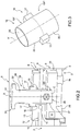
Figure 1 is a prospective and exploded view of a portable apparatus for subjecting snowpack samples to analysis that is implemented in accordance with this invention; -
Figure 2 is a partial and section view of the portable apparatus inFigure 1 ; and -
Figure 3 is a prospective view of a detail of the portable apparatus ofFigure 1 . - In
Figure 1 , the number 1 indicates in the entirety thereof, a portable apparatus for subjecting snowpack samples C to analysis. - In particular, the device 1 comprises a structure 2 which in turn comprises a
fixed guide structure 3 defined by two linear guides 4 that are parallel therebetween and twohead elements 6. As better described in the following discussion, acarriage 5 slides on linear guides 4. - The two linear guides 4 are connected, at the ends thereof, to the two
head elements 6 intended to act as a limit switch for thecarriage 5. - The structure 2 comprises a
plate 7 with a parallelepiped shape having a reduced thickness (on the order of 5-10 mm) and presenting a flatupper surface 8 and a flatlower surface 9. At the vertices of the lowerflat surface 9, fourappendages 10 are provided for the connection by appropriate fastening means (known and not described in detail) with the twohead elements 6. - The
plate 7 is equipped with a through opening 11 formed at a substantially central position and provided with an X-axis. Theaperture 11 is defined by a cylindrical surface with a diameter of between 20 and 50 mm, preferably between 25 and 35 mm. - According to a preferred variant, the diameter of the
aperture 11 is 30 mm. - The structure 2 also includes an
adapter 12 defined by a parallelepiped shaped plate with a thickness of between 5 and 15 mm. According to a preferred variant, the thickness of theadapter 12 is 10 mm. Theadapter 12 has a flatupper surface 13 and a flatlower surface 14. Thelower surface 14 is arranged in contact with (lies upon) theupper surface 8. - The
adapter 12 is connected, by appropriate fastening means (known and not described in detail) to theplate 7. Theadapter 12 preferably has, in plan view, dimensions that approximate, by default, the dimensions of theplate 7. Theadapter 12 is also provided with a through opening 15 formed at a substantially central and coaxial position with respect to the X-axis (and therefore coaxial, in use, to the opening 11). Theaperture 15 is defined by a cylindrical surface with the same diameter as theopening 11, i.e., a diameter of between 20 and 50 mm, preferably of between 25 and 35 mm. According to a preferred variant, the diameter of theaperture 15 is 30 mm. - Furthermore, the
adapter 12 is provided with twogrooves 16 intended to receive a respectivelateral rib 17 of asampling element 18, as better described in the following discussion. The twogrooves 16 are formed at the opening 15. In particular, thegrooves 16 are formed at diametrically opposite ends (with respect to the X-axis) of theopening 15. Thegrooves 16 are formed at theupper surface 16. Eachgroove 16 is defined by a surface with a substantially flat base which is joined to a back wall (curved or flat) and two side walls, which are also substantially flat. - The
sampling element 18 is intended both to produce the snowpack core sample C to be analyzed and to receive the snowpack sample C during the analysis step. According to a preferred variant, thesampling element 18 is made of a plastic or metallic material; thesampling element 18 is preferably obtained by means of 3D molding techniques. - The
sampling element 18 is defined by atubular body 19 having aninner surface 20 with cylindrical symmetry around an X'-axis. Theinner surface 20 has a diameter of between 15 and 45 mm; preferably the diameter of theinner surface 20 is between 20 and 30 mm. - The
tubular body 19 is divided into acoring portion 19* and ananalysis portion 19** joined together at anouter edge 21. Thecoring portion 19* and themeasurement portion 19** have respective substantially uniform extensions along the X'-axis. According to alternative embodiments, theportions 19* and 19** may be uniform or non-uniform, symmetrical or non-symmetrical, therebetween. - Preferably (but not exclusively), the
coring portion 19* has an extension along the X'-axis of between 15 and 30 mm, preferably equal to 22 mm. In this case, the dimensions of thecoring portion 19* make it possible to isolate samples C of a single layer from the layers that define the snowpack. In this way it is possible, by means of differing samplings, to take samples C of the individual layers of snowpack that are responsible for the performance of the pneumatic tyres on snow and evaluate the shear resistance thereof. - The
analysis portion 19** has anouter surface 22 that is cylindrical and coaxial with respect to the X'-axis. - The
coring portion 19* has instead an outer truncated-cone surface 23 that is coaxial to the X'-axis. - In other words, the
outer surface 23 gradually widens towards theanalysis portion 19**. The cylindricalouter surface 22 therefore has a diameter equal to the larger diameter of the outer truncated-cone surface 23. The particular shape of thecoring portion 19* makes it possible to penetrate the snowpack, isolate, detach and retain the snowpack sample C within the area defined by theinner surface 20. - Furthermore, the
sampling element 18 carries, and is connected to, the twolateral ribs 17 which extend laterally from theouter surfaces lateral ribs 17 are substantially arranged at the edging 21. Thelateral ribs 17 are arranged at the extremity therebetween, diametrically opposite (with respect to the X'-axis) theouter surfaces lateral ribs 17 have a shape that is complementary to the shape of thegrooves 16. In particular, eachlateral rib 17 is provided with respective opposing bottom surfaces which are arranged, when in use, in abutment on the bottom surface of therespective groove 16, in such a way that the distance between the lower end of thesampling element 18 and the upper end of thecarriage 5 is between 0.1 and 3 mm. It is important to highlight that both ends of thelateral ribs 17 have a shape that is complementary to the shape of thegrooves 16. In other words, both the ends of thelateral ribs 17 facing the coringportion 19* and the ends of thelateral ribs 17 facing theanalysis portion 19** have complementary shapes to the shape of thegrooves 16 and are intended to engage, in use, with thegrooves 16. - The
carriage 5 is defined by a box-like body 24 provided with aseat 25 for partially receiving the snowpack sample C of the snowpack and is arranged, in use, below theplate 7. In use, thecarriage 5 is housed in such a way that theseat 25 is turned towards and directly facing theplate 7. Theseat 25 is defined by acircular bottom surface 26 and by a cylindricallateral surface 27 having a diameter that approximates the diameter of theinner surface 20. Theseat 25 has a variable height of between 1 mm and 20 mm; preferably, the height of theseat 25 is between 8 and 15 mm. The height of theseat 25 is modified (adjusted) by means of the insertion of a number of disc shims (not shown) of suitable height within theseat 25 itself. Underneath, thecarriage 5 is connected to fourbearings 28 which allow for the sliding of thecarriage 5 itself on tworails 3. - A front end of the
carriage 5 is provided with anappendix 5* that protrudes such as to be interposed, when in use, between the tworails 3. In a front surface of the box-like body 24 there is a groove which together with theappendix 5* defines a housing that is intended to house a load cell for detecting the shear strength of the snowpack sample C. - According to further variants, as an alternative to the load cell, the apparatus 1 may comprise a piezoelectric force sensor or a magnetic force sensor or a hydraulic force sensor.
- The apparatus 1 comprises a compressive member, in particular a
piston 29, having acylindrical body 30 that is intended to slide within thesampling element 18 and an upper handle 31 (or knob). - Clearly, the
cylindrical body 30 is provided with a cylindrical outer surface wherein the diameter thereof approximates, by default, the diameter of theinner surface 20. - Finally, the apparatus comprises an
actuating device 32, in particular an electric motor, which is connected to thecarriage 5 and that is suitable for sliding thecarriage 5 on therails 3. According to a first variant, theactuating device 32 is arranged externally to the box-like body 24, within a dedicated housing. According to a further variant, theactuating device 32 is housed within the box-like body 24. - Advantageously, a further load cell is provided in order to detect the compression force exerted by the
piston 29 upon the snowpack sample C; the further load cell is preferably housed on thepiston 29. - The following describes the method for using the portable apparatus 1 in subjecting to analysis snowpack samples C, as described heretofore.
- In the first place, the operator proceeds manually to implementing the sampling (coring) of the snowpack sample C for analysis. The snowpack sample C is taken in penetrating into the snowpack using the
coring portion 19*, such that the snowpack sample C engages with the seat defined, within thecoring portion 19* itself, by theinner surface 20. At this stage, theanalysis portion 19** is used by the operator to grasp thesampling element 18, whilst thecoring portion 19* serves as a core barrel; the outer truncated-cone surface 23 in fact allows for the penetration into the snowpack whilst theinner surface 20 protects and houses the snowpack sample C. - When the
sampling element 18 reaches a depth such as to encompass the entire thickness of the layer of snow to be analyzed, the sampling step is concluded. - Once the sampling step has been completed, the
sampling element 18 is extracted from the snowpack and inserted into the structure 2, in such a way as to coincide with the X' and X axes. Thesampling element 18 acts, in this case, as a centering pin. - According to alternative therebetween embodiments and as a function of the snowpack layer to be analyzed, the
analysis portion 19** or else thecoring portion 19* is inserted within theopenings - According to a first variant, the
analysis portion 19** is inserted within theopenings analysis portion 19** slides inside theopenings lateral rib 17 has engaged with therespective groove 16. Theanalysis portion 19** protrudes (juts out from theplate 7 downwards) such as to partially fill the free space between theplate 7 and thecarriage 5. It is important to highlight that theanalysis portion 19** (in particular, a bottom surface of theanalysis portion 19**) is arranged in the vicinity of a flat upper surface of thecarriage 5, but not in contact (i.e., not resting in contact) with thecarriage 5. In other words, during the analysis step, theanalysis portion 19** and thecarriage 5 are separated by a gap (slit or slot) of a few mm, in particular the dimensions of said interstice are between 0.1 and 3 mm. - The
carriage 5 is located below thesampling element 18, such that theseat 25 is coaxial to theopenings seat 25 is facing thesampling element 18 such as to partially receive the snowpack sample C. - Subsequently, the
piston 29 is inserted and made to slide, inside thesampling element 18, by an operator. Preferably, the pressure exerted by the operator on the snowpack sample C by means of thepiston 29 is detected by means of the further load cell housed on thepiston 29. - The snowpack sample C slides downwards (i.e., towards the carriage 5) until the load, detected by the load cell at the
piston head 29, reaches a target compression value, determined at a preliminary stage of the analysis. In the position wherein the load, detected by the load cell in thepiston head 29, has reached the target compression value shown inFigure 2 , the snowpack sample C is partially housed within theseat 25 and partially housed within theanalysis portion 19**. - Finally, the
actuating device 32 is driven in order to allow the sliding of thecarriage 5 upon therails 3; the shear strength of the snowpack sample C is detected by means of the load cell. - According to a further variant, the coring
portion 19*, after the actual coring step, is inserted directly within theopenings portion 19* slides inside theopenings lateral rib 17 has engaged with therespective groove 16. The coringportion 19* protrudes (juts out from theplate 7 downwards) such as to partially fill the free space between theplate 7 and thecarriage 5. It is important to highlight that thecoring portion 19* (in particular, a bottom surface of thecoring portion 19*) is arranged in the vicinity of a flat upper surface of thecarriage 5, but not in contact (i.e., not resting in contact) with thecarriage 5. - In other words, during the analysis step, the coring
portion 19* and thecarriage 5 are separated by an interstice (slit or slot) of a few mm, in particular the dimensions of said interstice are between 0.1 and 3 mm. - The
carriage 5 is located below thesampling element 18, such that theseat 25 is coaxial to theopenings seat 25 is facing thesampling element 18 such as to partially receive the snowpack sample C. - Subsequently, the
piston 29 is inserted and made to slide, inside thesampling element 18, by an operator. Preferably, the pressure exerted by the operator on the snowpack sample C by means of thepiston 29 is detected by means of the further load cell housed on thepiston 29. - The snowpack sample C slides downwards (i.e., towards the carriage 5) until the load, detected by the load cell at the
piston head 29, reaches a target compression value, determined at a preliminary stage of the analysis. In the position wherein the load, detected by the load cell in thepiston head 29, has reached the target compression value shown inFigure 2 , the snowpack sample C is partially housed within theseat 25 and partially housed within thecoring portion 19*. - Finally, the
actuating device 32 is driven in order to allow the sliding of thecarriage 5 upon therails 3; the shear strength of the snowpack sample C is detected by means of the load cell. - It has been shown experimentally that the measurement of the shear strength of the snowpack sample C, performed by means of the portable apparatus 1 described in the foregoing discussion, is extremely reliable; the measurement by means of the load cell provides comparable values to shear strength values measured using other techniques.
- The portable apparatus 1 is used to measure the shear strength of snowpack samples C, with the same characteristics, taken from subsequent corings and in exerting different pressure values on the sample C. Alternatively, it is possible to exert a constant pressure and to measure the shear strength of snowpack samples C taken from subsequent corings from different layers of the snowpack.
- It is important to note that the method for subjecting the snowpack samples C to analysis, as described heretofore, do not provide for any transfer of the snowpack sample C between the coring/withdrawal and the actual analysis step. In this way, in reducing the manipulation of the snowpack sample C by operators, it is possible to not affect the properties of the snowpack sample C.
- The apparatus 1, thus far described, has numerous advantages. Firstly, the apparatus 1 described above makes it possible to significantly reduce manipulation of the snowpack samples C, from the coring step to the actual analysis step. In fact, the apparatus 1 as described heretofore makes it possible, after the coring step, for the
sampling element 18 to be overturned, but not further transferred or handled. - In addition, the apparatus 1 has extremely compact dimensions that make it possible to move it in an easy manner and to perform in-situ analysis, as well as allowing for a significant improvement in the repeatability of the analysis allowing for the withdrawal of perfectly uniform snowpack samples C; finally, the apparatus 1 is used to evaluate, one at a time, individual layers of the snowpack in an extremely reliable way.
-
- 1
- portable apparatus
- 2
- structure
- 3
- guide system
- 4
- linear guide
- 5
- carriage
- 5*
- extension
- 6
- head elements
- 7
- plate
- 8
- upper surface
- 9
- lower surface
- 10
- extensions
- 11
- opening
- 12
- adapter
- 13
- upper surface
- 14
- lower surface
- 15
- opening
- 16
- grooves
- 17
- lateral ribs
- 18
- sampling element
- 19
- tubular body
- 20
- inner surface
- 21
- outer edging
- 22
- outer surface
- 23
- outer surface
- 24
- body
- 25
- seat
- 26
- bottom surface
- 27
- lateral surface
- 28
- bearings
- 29
- piston
- 30
- cylindrical body
- 31
- handle
- 32
- electric motor
- X'
- axis
- X
- axis
- C
- snowpack
- 19*
- coring portion
- 19**
- analysis portion
Claims (16)
- Portable apparatus (1) for subjecting a snowpack sample (C) to analysis comprising
a structure (2) provided in turn with:- a fixed guide structure (3) defined by two linear guides (4);- a plate (7) provided with a first through opening (11) having cylindrical symmetry about a first axis (X);- a carriage (5) that slides on the linear guides (4) and that is provided with a seat (25) that is intended to house, at least partially, the snowpack sample (C) and facing, in use, the first through opening (11);a carriage (5) actuating device (32); and
an extractable sampling element (18), implemented by means of a tubular body (19) having an inner surface (20) with cylindrical symmetry about a second axis (X') which defines a seat for receiving the snowpack sample (C);
the apparatus is characterized in that the extractable sampling element (18) is divided into a coring portion (19*) and an analysis portion (19**); wherein the coring portion (19*) has an outer truncated-cone surface (23) that is suitable for penetrating into the snowpack in order to isolate and retain the sample (C) within the seat defined by the inner surface (20); and wherein the analysis portion (19**) has an outer cylindrical surface (22) having a diameter that substantially approximates the diameter of the first through opening (11). - Apparatus according to claim 1, wherein the sampling element (18) comprises a number of lateral ribs (17) which protrude from the lateral surface (22, 23); and wherein the structure (2) comprises a number of grooves (16), each one of which is intended to receive a respective lateral rib (17) during the snowpack sample (C) analysis step.
- Apparatus according to claim 1 or 2, wherein the coring portion (19*) and the analysis portion (19**) are joined together at an outer edge (21); and wherein the sampling element (18) comprises a number of lateral ribs (17) which protrude from the lateral surface (22, 23) at the outer edge (21).
- Apparatus according to any one of the preceding claims, wherein the inner surface (20) has a diameter of between 15 and 45 mm; preferably the diameter of the inner surface (20) is between 20 and 30 mm.
- Apparatus according to any one of the preceding claims, wherein the outer cylindrical surface (22) has a diameter which coincides with the larger diameter of the outer truncated-cone surface (23).
- Apparatus according to any one of the preceding claims, wherein the coring portion (19*) has an extension along the second axis (X') of between 15 and 30 mm, such as to isolate samples (C) of a single layer from between those layers that define the snowpack.
- Apparatus according to any one of the preceding claims and comprising a member (29) for the compression of the snowpack sample (C) having a cylindrical body (30) that is intended to slide inside the sampling element (18).
- Apparatus according to claim 7, wherein the compression member (29) comprises a first load cell for measuring the compressive force exerted on the snowpack sample (C).
- Apparatus according to any one of the preceding claims, wherein the carriage (5) comprises a second load cell for measuring the shear strength of the snowpack sample (C).
- Apparatus according to any one of the preceding claims, wherein the structure (2) comprises an adapter (12) that is connected to the plate (7) and provided with a second through opening (15) that is coaxial to the first axis (X).
- Apparatus according to claim 10 when it depends on claim 2, wherein the grooves (16) are formed in the adapter (12).
- Apparatus according to any one of the preceding claims, wherein during the snowpack sample (C) analysis step, the end of the analysis portion (19**) and the carriage (5) are separated by an interstice with dimensions of between 0.1 and 3 mm.
- Method for subjecting a snowpack sample (C) to analysis by means of a portable apparatus (1) implemented according to any one of the claims from 1 to 12 and comprising:a step for the withdrawal, by means of the coring portion (19*), of a snowpack sample (C);a step for the insertion of the sampling element (18) within the through opening (11);a step of applying a pressure to the snowpack sample (C) in order to move it from a withdrawal position, wherein the sample (C) is entirely housed inside the sampling element (18), to an analysis position, wherein the sample (C) is partially housed within the sampling element (18) and partially within the seat (25);a step for controlling, by means of the actuation device (32), the movement of the carriage (5); anda step for measuring the shear strength of the snowpack sample (C).
- Method according to claim 13, wherein the insertion step provides for the insertion of the coring portion (19*) within the through opening (11).
- Method according to claim 14, wherein the insertion step provides for the insertion of the analysis portion (19**) within the through opening (11).
- Method according to any one of the claims from 13 to 15, wherein no further steps are provided for the processing or transferring of the snowpack sample (C) between the withdrawal step and the insertion step.
Applications Claiming Priority (1)
| Application Number | Priority Date | Filing Date | Title |
|---|---|---|---|
| IT102019000020086A IT201900020086A1 (en) | 2019-10-30 | 2019-10-30 | PORTABLE APPARATUS FOR ANALYSIS OF SNOW COVER SAMPLES AND RELATIVE METHOD OF ANALYSIS OF SNOW COVER SAMPLES |
Publications (2)
| Publication Number | Publication Date |
|---|---|
| EP3816606A1 true EP3816606A1 (en) | 2021-05-05 |
| EP3816606B1 EP3816606B1 (en) | 2023-02-22 |
Family
ID=69811598
Family Applications (1)
| Application Number | Title | Priority Date | Filing Date |
|---|---|---|---|
| EP20203625.7A Active EP3816606B1 (en) | 2019-10-30 | 2020-10-23 | Apparatus and method for the analysis of snowpack samples |
Country Status (3)
| Country | Link |
|---|---|
| EP (1) | EP3816606B1 (en) |
| FI (1) | FI3816606T3 (en) |
| IT (1) | IT201900020086A1 (en) |
Citations (3)
| Publication number | Priority date | Publication date | Assignee | Title |
|---|---|---|---|---|
| SU885865A1 (en) * | 1980-03-04 | 1981-11-30 | Предприятие П/Я А-7701 | Device for snow shift characteristic determination |
| JP2004125620A (en) * | 2002-10-02 | 2004-04-22 | Sumitomo Rubber Ind Ltd | Snow property measuring device |
| JP2004257892A (en) * | 2003-02-26 | 2004-09-16 | Sumitomo Rubber Ind Ltd | Snow property measurement device |
-
2019
- 2019-10-30 IT IT102019000020086A patent/IT201900020086A1/en unknown
-
2020
- 2020-10-23 FI FIEP20203625.7T patent/FI3816606T3/en active
- 2020-10-23 EP EP20203625.7A patent/EP3816606B1/en active Active
Patent Citations (3)
| Publication number | Priority date | Publication date | Assignee | Title |
|---|---|---|---|---|
| SU885865A1 (en) * | 1980-03-04 | 1981-11-30 | Предприятие П/Я А-7701 | Device for snow shift characteristic determination |
| JP2004125620A (en) * | 2002-10-02 | 2004-04-22 | Sumitomo Rubber Ind Ltd | Snow property measuring device |
| JP2004257892A (en) * | 2003-02-26 | 2004-09-16 | Sumitomo Rubber Ind Ltd | Snow property measurement device |
Non-Patent Citations (1)
| Title |
|---|
| DAVID M MC CLUNG: "DIRECT SIMPLE SHEAR TESTS ON SNOW AND THEIR RELATION TO SLAB AVALANCHE FORMATION", JOURNAL OF GLACIOLOGY, vol. 19, no. 81, 1 January 1977 (1977-01-01), pages 101 - 109, XP055715921 * |
Also Published As
| Publication number | Publication date |
|---|---|
| IT201900020086A1 (en) | 2021-04-30 |
| FI3816606T3 (en) | 2023-04-18 |
| EP3816606B1 (en) | 2023-02-22 |
Similar Documents
| Publication | Publication Date | Title |
|---|---|---|
| WO2007144606A3 (en) | Mass spectrometry biomarker assay | |
| JP2016186497A (en) | Microtome equipped with a surface orientation sensor that senses the orientation of the sample surface | |
| EP3816606B1 (en) | Apparatus and method for the analysis of snowpack samples | |
| KR102099399B1 (en) | Apparatus for measuring an inside diameter | |
| WO2007112751A3 (en) | Tissue sample collection system with visual sample inspection | |
| US7247275B2 (en) | Gel extraction device | |
| US9091672B2 (en) | Retaining device for a pipetting needle | |
| US20040227086A1 (en) | Method and device for NIR reflection spectroscopy | |
| CN113495014A (en) | A vibrating gravity sampler for geotechnical parameter normal position test | |
| EP3662253A1 (en) | System for analyzing impact and puncture resistance | |
| JPH01502295A (en) | Device for measuring the softness of meat | |
| KR20190115784A (en) | Core biopsy device | |
| CN1800851A (en) | Core sampling device intended to assemble tissue arrays | |
| KR20170138064A (en) | Biopsy device | |
| CN113418756B (en) | Food safety cereal sampling detecting system | |
| EP1631815B1 (en) | Materials testing | |
| CN219573913U (en) | Meat freshness detection device based on near infrared spectrum technology | |
| KR101441997B1 (en) | Portable type hand press for preparing sample for xrf measurement | |
| JP4206370B2 (en) | Positioning device for inspection elements | |
| CN210783138U (en) | A check-up mould for examining sole | |
| CN208999117U (en) | A kind of Pharmaceutical Analysis drug sampler | |
| CN224081217U (en) | Environment geology soil sampling device | |
| KR20100104640A (en) | Durability testing apparatus for powerwindow switch | |
| CN114965024A (en) | Be used for medical treatment operation instrument intensity detection device | |
| CN215262847U (en) | Soil sample compression modulus measuring device |
Legal Events
| Date | Code | Title | Description |
|---|---|---|---|
| PUAI | Public reference made under article 153(3) epc to a published international application that has entered the european phase |
Free format text: ORIGINAL CODE: 0009012 |
|
| STAA | Information on the status of an ep patent application or granted ep patent |
Free format text: STATUS: THE APPLICATION HAS BEEN PUBLISHED |
|
| AK | Designated contracting states |
Kind code of ref document: A1 Designated state(s): AL AT BE BG CH CY CZ DE DK EE ES FI FR GB GR HR HU IE IS IT LI LT LU LV MC MK MT NL NO PL PT RO RS SE SI SK SM TR |
|
| STAA | Information on the status of an ep patent application or granted ep patent |
Free format text: STATUS: REQUEST FOR EXAMINATION WAS MADE |
|
| 17P | Request for examination filed |
Effective date: 20211105 |
|
| RBV | Designated contracting states (corrected) |
Designated state(s): AL AT BE BG CH CY CZ DE DK EE ES FI FR GB GR HR HU IE IS IT LI LT LU LV MC MK MT NL NO PL PT RO RS SE SI SK SM TR |
|
| GRAP | Despatch of communication of intention to grant a patent |
Free format text: ORIGINAL CODE: EPIDOSNIGR1 |
|
| STAA | Information on the status of an ep patent application or granted ep patent |
Free format text: STATUS: GRANT OF PATENT IS INTENDED |
|
| RIC1 | Information provided on ipc code assigned before grant |
Ipc: G01N 33/18 20060101ALI20220325BHEP Ipc: G01N 19/02 20060101ALI20220325BHEP Ipc: G01N 3/24 20060101AFI20220325BHEP |
|
| INTG | Intention to grant announced |
Effective date: 20220425 |
|
| GRAJ | Information related to disapproval of communication of intention to grant by the applicant or resumption of examination proceedings by the epo deleted |
Free format text: ORIGINAL CODE: EPIDOSDIGR1 |
|
| STAA | Information on the status of an ep patent application or granted ep patent |
Free format text: STATUS: REQUEST FOR EXAMINATION WAS MADE |
|
| GRAP | Despatch of communication of intention to grant a patent |
Free format text: ORIGINAL CODE: EPIDOSNIGR1 |
|
| STAA | Information on the status of an ep patent application or granted ep patent |
Free format text: STATUS: GRANT OF PATENT IS INTENDED |
|
| INTC | Intention to grant announced (deleted) | ||
| INTG | Intention to grant announced |
Effective date: 20220914 |
|
| GRAS | Grant fee paid |
Free format text: ORIGINAL CODE: EPIDOSNIGR3 |
|
| GRAA | (expected) grant |
Free format text: ORIGINAL CODE: 0009210 |
|
| STAA | Information on the status of an ep patent application or granted ep patent |
Free format text: STATUS: THE PATENT HAS BEEN GRANTED |
|
| AK | Designated contracting states |
Kind code of ref document: B1 Designated state(s): AL AT BE BG CH CY CZ DE DK EE ES FI FR GB GR HR HU IE IS IT LI LT LU LV MC MK MT NL NO PL PT RO RS SE SI SK SM TR |
|
| REG | Reference to a national code |
Ref country code: GB Ref legal event code: FG4D |
|
| REG | Reference to a national code |
Ref country code: CH Ref legal event code: EP |
|
| REG | Reference to a national code |
Ref country code: DE Ref legal event code: R096 Ref document number: 602020008250 Country of ref document: DE |
|
| REG | Reference to a national code |
Ref country code: AT Ref legal event code: REF Ref document number: 1549806 Country of ref document: AT Kind code of ref document: T Effective date: 20230315 Ref country code: IE Ref legal event code: FG4D |
|
| REG | Reference to a national code |
Ref country code: SE Ref legal event code: TRGR |
|
| RAP4 | Party data changed (patent owner data changed or rights of a patent transferred) |
Owner name: BRIDGESTONE EUROPE NV/SA |
|
| REG | Reference to a national code |
Ref country code: LT Ref legal event code: MG9D |
|
| P01 | Opt-out of the competence of the unified patent court (upc) registered |
Effective date: 20230511 |
|
| REG | Reference to a national code |
Ref country code: NL Ref legal event code: MP Effective date: 20230222 |
|
| REG | Reference to a national code |
Ref country code: AT Ref legal event code: MK05 Ref document number: 1549806 Country of ref document: AT Kind code of ref document: T Effective date: 20230222 |
|
| PG25 | Lapsed in a contracting state [announced via postgrant information from national office to epo] |
Ref country code: RS Free format text: LAPSE BECAUSE OF FAILURE TO SUBMIT A TRANSLATION OF THE DESCRIPTION OR TO PAY THE FEE WITHIN THE PRESCRIBED TIME-LIMIT Effective date: 20230222 Ref country code: PT Free format text: LAPSE BECAUSE OF FAILURE TO SUBMIT A TRANSLATION OF THE DESCRIPTION OR TO PAY THE FEE WITHIN THE PRESCRIBED TIME-LIMIT Effective date: 20230622 Ref country code: NO Free format text: LAPSE BECAUSE OF FAILURE TO SUBMIT A TRANSLATION OF THE DESCRIPTION OR TO PAY THE FEE WITHIN THE PRESCRIBED TIME-LIMIT Effective date: 20230522 Ref country code: NL Free format text: LAPSE BECAUSE OF FAILURE TO SUBMIT A TRANSLATION OF THE DESCRIPTION OR TO PAY THE FEE WITHIN THE PRESCRIBED TIME-LIMIT Effective date: 20230222 Ref country code: LV Free format text: LAPSE BECAUSE OF FAILURE TO SUBMIT A TRANSLATION OF THE DESCRIPTION OR TO PAY THE FEE WITHIN THE PRESCRIBED TIME-LIMIT Effective date: 20230222 Ref country code: LT Free format text: LAPSE BECAUSE OF FAILURE TO SUBMIT A TRANSLATION OF THE DESCRIPTION OR TO PAY THE FEE WITHIN THE PRESCRIBED TIME-LIMIT Effective date: 20230222 Ref country code: HR Free format text: LAPSE BECAUSE OF FAILURE TO SUBMIT A TRANSLATION OF THE DESCRIPTION OR TO PAY THE FEE WITHIN THE PRESCRIBED TIME-LIMIT Effective date: 20230222 Ref country code: ES Free format text: LAPSE BECAUSE OF FAILURE TO SUBMIT A TRANSLATION OF THE DESCRIPTION OR TO PAY THE FEE WITHIN THE PRESCRIBED TIME-LIMIT Effective date: 20230222 Ref country code: AT Free format text: LAPSE BECAUSE OF FAILURE TO SUBMIT A TRANSLATION OF THE DESCRIPTION OR TO PAY THE FEE WITHIN THE PRESCRIBED TIME-LIMIT Effective date: 20230222 |
|
| PG25 | Lapsed in a contracting state [announced via postgrant information from national office to epo] |
Ref country code: PL Free format text: LAPSE BECAUSE OF FAILURE TO SUBMIT A TRANSLATION OF THE DESCRIPTION OR TO PAY THE FEE WITHIN THE PRESCRIBED TIME-LIMIT Effective date: 20230222 Ref country code: IS Free format text: LAPSE BECAUSE OF FAILURE TO SUBMIT A TRANSLATION OF THE DESCRIPTION OR TO PAY THE FEE WITHIN THE PRESCRIBED TIME-LIMIT Effective date: 20230622 Ref country code: GR Free format text: LAPSE BECAUSE OF FAILURE TO SUBMIT A TRANSLATION OF THE DESCRIPTION OR TO PAY THE FEE WITHIN THE PRESCRIBED TIME-LIMIT Effective date: 20230523 |
|
| PG25 | Lapsed in a contracting state [announced via postgrant information from national office to epo] |
Ref country code: SM Free format text: LAPSE BECAUSE OF FAILURE TO SUBMIT A TRANSLATION OF THE DESCRIPTION OR TO PAY THE FEE WITHIN THE PRESCRIBED TIME-LIMIT Effective date: 20230222 Ref country code: RO Free format text: LAPSE BECAUSE OF FAILURE TO SUBMIT A TRANSLATION OF THE DESCRIPTION OR TO PAY THE FEE WITHIN THE PRESCRIBED TIME-LIMIT Effective date: 20230222 Ref country code: EE Free format text: LAPSE BECAUSE OF FAILURE TO SUBMIT A TRANSLATION OF THE DESCRIPTION OR TO PAY THE FEE WITHIN THE PRESCRIBED TIME-LIMIT Effective date: 20230222 Ref country code: DK Free format text: LAPSE BECAUSE OF FAILURE TO SUBMIT A TRANSLATION OF THE DESCRIPTION OR TO PAY THE FEE WITHIN THE PRESCRIBED TIME-LIMIT Effective date: 20230222 Ref country code: CZ Free format text: LAPSE BECAUSE OF FAILURE TO SUBMIT A TRANSLATION OF THE DESCRIPTION OR TO PAY THE FEE WITHIN THE PRESCRIBED TIME-LIMIT Effective date: 20230222 |
|
| REG | Reference to a national code |
Ref country code: DE Ref legal event code: R097 Ref document number: 602020008250 Country of ref document: DE |
|
| PG25 | Lapsed in a contracting state [announced via postgrant information from national office to epo] |
Ref country code: SK Free format text: LAPSE BECAUSE OF FAILURE TO SUBMIT A TRANSLATION OF THE DESCRIPTION OR TO PAY THE FEE WITHIN THE PRESCRIBED TIME-LIMIT Effective date: 20230222 |
|
| PLBE | No opposition filed within time limit |
Free format text: ORIGINAL CODE: 0009261 |
|
| STAA | Information on the status of an ep patent application or granted ep patent |
Free format text: STATUS: NO OPPOSITION FILED WITHIN TIME LIMIT |
|
| 26N | No opposition filed |
Effective date: 20231123 |
|
| PG25 | Lapsed in a contracting state [announced via postgrant information from national office to epo] |
Ref country code: SI Free format text: LAPSE BECAUSE OF FAILURE TO SUBMIT A TRANSLATION OF THE DESCRIPTION OR TO PAY THE FEE WITHIN THE PRESCRIBED TIME-LIMIT Effective date: 20230222 |
|
| PG25 | Lapsed in a contracting state [announced via postgrant information from national office to epo] |
Ref country code: IT Free format text: LAPSE BECAUSE OF FAILURE TO SUBMIT A TRANSLATION OF THE DESCRIPTION OR TO PAY THE FEE WITHIN THE PRESCRIBED TIME-LIMIT Effective date: 20230222 Ref country code: MC Free format text: LAPSE BECAUSE OF FAILURE TO SUBMIT A TRANSLATION OF THE DESCRIPTION OR TO PAY THE FEE WITHIN THE PRESCRIBED TIME-LIMIT Effective date: 20230222 |
|
| REG | Reference to a national code |
Ref country code: CH Ref legal event code: PL |
|
| REG | Reference to a national code |
Ref country code: BE Ref legal event code: MM Effective date: 20231031 |
|
| PG25 | Lapsed in a contracting state [announced via postgrant information from national office to epo] |
Ref country code: CH Free format text: LAPSE BECAUSE OF NON-PAYMENT OF DUE FEES Effective date: 20231031 |
|
| PG25 | Lapsed in a contracting state [announced via postgrant information from national office to epo] |
Ref country code: CH Free format text: LAPSE BECAUSE OF NON-PAYMENT OF DUE FEES Effective date: 20231031 |
|
| PG25 | Lapsed in a contracting state [announced via postgrant information from national office to epo] |
Ref country code: BE Free format text: LAPSE BECAUSE OF NON-PAYMENT OF DUE FEES Effective date: 20231031 |
|
| PG25 | Lapsed in a contracting state [announced via postgrant information from national office to epo] |
Ref country code: IE Free format text: LAPSE BECAUSE OF NON-PAYMENT OF DUE FEES Effective date: 20231023 |
|
| PG25 | Lapsed in a contracting state [announced via postgrant information from national office to epo] |
Ref country code: IE Free format text: LAPSE BECAUSE OF NON-PAYMENT OF DUE FEES Effective date: 20231023 |
|
| PG25 | Lapsed in a contracting state [announced via postgrant information from national office to epo] |
Ref country code: BG Free format text: LAPSE BECAUSE OF FAILURE TO SUBMIT A TRANSLATION OF THE DESCRIPTION OR TO PAY THE FEE WITHIN THE PRESCRIBED TIME-LIMIT Effective date: 20230222 |
|
| PG25 | Lapsed in a contracting state [announced via postgrant information from national office to epo] |
Ref country code: BG Free format text: LAPSE BECAUSE OF FAILURE TO SUBMIT A TRANSLATION OF THE DESCRIPTION OR TO PAY THE FEE WITHIN THE PRESCRIBED TIME-LIMIT Effective date: 20230222 |
|
| GBPC | Gb: european patent ceased through non-payment of renewal fee |
Effective date: 20241023 |
|
| PG25 | Lapsed in a contracting state [announced via postgrant information from national office to epo] |
Ref country code: GB Free format text: LAPSE BECAUSE OF NON-PAYMENT OF DUE FEES Effective date: 20241023 |
|
| PG25 | Lapsed in a contracting state [announced via postgrant information from national office to epo] |
Ref country code: CY Free format text: LAPSE BECAUSE OF FAILURE TO SUBMIT A TRANSLATION OF THE DESCRIPTION OR TO PAY THE FEE WITHIN THE PRESCRIBED TIME-LIMIT; INVALID AB INITIO Effective date: 20201023 |
|
| PG25 | Lapsed in a contracting state [announced via postgrant information from national office to epo] |
Ref country code: HU Free format text: LAPSE BECAUSE OF FAILURE TO SUBMIT A TRANSLATION OF THE DESCRIPTION OR TO PAY THE FEE WITHIN THE PRESCRIBED TIME-LIMIT; INVALID AB INITIO Effective date: 20201023 |
|
| PGFP | Annual fee paid to national office [announced via postgrant information from national office to epo] |
Ref country code: FI Payment date: 20250923 Year of fee payment: 6 |
|
| PGFP | Annual fee paid to national office [announced via postgrant information from national office to epo] |
Ref country code: LU Payment date: 20250923 Year of fee payment: 6 |
|
| PGFP | Annual fee paid to national office [announced via postgrant information from national office to epo] |
Ref country code: FR Payment date: 20250924 Year of fee payment: 6 |
|
| PGFP | Annual fee paid to national office [announced via postgrant information from national office to epo] |
Ref country code: SE Payment date: 20250923 Year of fee payment: 6 |
|
| PG25 | Lapsed in a contracting state [announced via postgrant information from national office to epo] |
Ref country code: TR Free format text: LAPSE BECAUSE OF FAILURE TO SUBMIT A TRANSLATION OF THE DESCRIPTION OR TO PAY THE FEE WITHIN THE PRESCRIBED TIME-LIMIT Effective date: 20230222 |
|
| PGFP | Annual fee paid to national office [announced via postgrant information from national office to epo] |
Ref country code: DE Payment date: 20250923 Year of fee payment: 6 |