EP3816464B1 - A screw cap - Google Patents
A screw cap Download PDFInfo
- Publication number
- EP3816464B1 EP3816464B1 EP20190974.4A EP20190974A EP3816464B1 EP 3816464 B1 EP3816464 B1 EP 3816464B1 EP 20190974 A EP20190974 A EP 20190974A EP 3816464 B1 EP3816464 B1 EP 3816464B1
- Authority
- EP
- European Patent Office
- Prior art keywords
- screw cap
- screw
- head
- screw head
- wheel
- Prior art date
- Legal status (The legal status is an assumption and is not a legal conclusion. Google has not performed a legal analysis and makes no representation as to the accuracy of the status listed.)
- Active
Links
Images


Classifications
-
- F—MECHANICAL ENGINEERING; LIGHTING; HEATING; WEAPONS; BLASTING
- F16—ENGINEERING ELEMENTS AND UNITS; GENERAL MEASURES FOR PRODUCING AND MAINTAINING EFFECTIVE FUNCTIONING OF MACHINES OR INSTALLATIONS; THERMAL INSULATION IN GENERAL
- F16B—DEVICES FOR FASTENING OR SECURING CONSTRUCTIONAL ELEMENTS OR MACHINE PARTS TOGETHER, e.g. NAILS, BOLTS, CIRCLIPS, CLAMPS, CLIPS OR WEDGES; JOINTS OR JOINTING
- F16B37/00—Nuts or like thread-engaging members
- F16B37/14—Cap nuts; Nut caps or bolt caps
-
- B—PERFORMING OPERATIONS; TRANSPORTING
- B60—VEHICLES IN GENERAL
- B60B—VEHICLE WHEELS; CASTORS; AXLES FOR WHEELS OR CASTORS; INCREASING WHEEL ADHESION
- B60B3/00—Disc wheels, i.e. wheels with load-supporting disc body
- B60B3/14—Attaching disc body to hub ; Wheel adapters
- B60B3/16—Attaching disc body to hub ; Wheel adapters by bolts or the like
- B60B3/165—Attaching disc body to hub ; Wheel adapters by bolts or the like with locking devices for the fixing means, e.g. screw or nut covers
-
- F—MECHANICAL ENGINEERING; LIGHTING; HEATING; WEAPONS; BLASTING
- F16—ENGINEERING ELEMENTS AND UNITS; GENERAL MEASURES FOR PRODUCING AND MAINTAINING EFFECTIVE FUNCTIONING OF MACHINES OR INSTALLATIONS; THERMAL INSULATION IN GENERAL
- F16B—DEVICES FOR FASTENING OR SECURING CONSTRUCTIONAL ELEMENTS OR MACHINE PARTS TOGETHER, e.g. NAILS, BOLTS, CIRCLIPS, CLAMPS, CLIPS OR WEDGES; JOINTS OR JOINTING
- F16B41/00—Measures against loss of bolts, nuts, or pins; Measures against unauthorised operation of bolts, nuts or pins
- F16B41/005—Measures against unauthorised operation of bolts, nuts or pins
Definitions
- the invention concerns a screw cap for covering wheel screws including wheel fasteners, such as wheel bolts, and anti-theft wheel fasteners.
- present invention relates to a screw cap suitable for installation with two different screw head types.
- the screw cap of the present invention is generally used in the automotive industry, for example, the screw cap may be installed onto wheel fasteners and anti-theft wheel fasteners of cars, vans, heavy goods vehicles, buses and the like.
- Wheel screws generally include wheel fasteners, including bolts, screws, nuts and the like, and serve to affix a wheel of a vehicle to a wheel hub of a vehicle.
- Some screw sets for wheels may include at least one anti-theft wheel fasteners, which are substantially similar to wheel fasteners, except that they include a specifically designed head that can only be used with a corresponding key for installation or removal of the anti-theft wheel fasteners.
- the key and the head of an anti-theft wheel fastener are generally unique.
- each wheel may include a single anti-theft wheel fastener, and a plurality of normal wheel fasteners (i.e. normal screw heads). In this way, the anti-theft wheel fastener prevents theft of the wheel from the vehicle.
- a screw cap 10 having a generally hexagonal engaging portion may be used to affix the screw cap to a hexagonal head of a wheel fastener.
- a screw cap 10 having a generally cylindrical engaging portion may be used to affix the screw cap to a circular head of an anti-theft wheel fasteners. In this way, two different screw caps are required to protect wheel fasteners and anti-theft wheel fasteners.
- the present invention proposes a single screw cap that can be used with two types of screw head. More particularly, the screw cap can be used with both wheel fastener screw heads and anti-theft wheel fastener screw heads. More particularly, the present invention proposes a screw cap that reduces manufacturing time, costs and is more aesthetically suitable for the end user.
- a screw cap for a screw head comprising a tubular body, having an end wall at a distal end portion and an opening at a proximal end portion along a centre axis; at least one first coupling member arranged coaxially to said centre axis at said distal end portion, adapted to retainingly receive at least a portion of a first-type screw head; and at least one second coupling member arranged coaxially with, and axially proximal to, said at least one first coupling member, adapted to retainingly receive at least a portion of a second-type screw head.
- This provides the advantage that a single screw cap can be manufactured and installed to accommodate two types of wheel screw head.
- this provides the advantage that a single screw cap may be manufactured and installed to accommodate both a head of a wheel fastener and a head of an anti-theft wheel fasteners.
- said second coupling member comprises at least two circumferentially spaced apart rib members, each rib member extending radially inwardly from an inner surface of said tubular body so as to couplingly engage with at least a portion of the second-type screw head, during use.
- said at least two rib members are adapted to provide a friction fit with at least a portion of the second-type screw head, during use.
- the screw cap comprises at least six circumferentially equidistantly spaced apart rib members.
- the diameter defined by the circumferentially spaced apart rib members is greater than the diameter defined by the annularly shaped recess.
- each screw cap installed to a wheel screw on a wheel of a vehicle appears substantially identical in height and form once installed, irrespective of the wheel screw to which the screw cap is affixed.
- the first-type screw head is a hexagonal screw head.
- the second-type screw head is a circular screw head.
- the screw cap comprises a resilient material.
- the screw cap comprises a polymer material.
- the end wall comprises a central bore adapted to receive a corresponding tool key.
- the described example embodiment relates to a screw cap, and in particular a screw cap which can be installed onto two different types of screw heads. More particularly, the screw cap can be installed onto both a head of a wheel fastener and a head of an-anti theft wheel fastener.
- the terms 'connected', ⁇ affixed' and the like are intended to include direct connections between two members without any other members interposed therebetween, as well as, indirect connections between members in which one or more other members are interposed therebetween.
- the terminology includes the words specifically mentioned above, derivatives thereof, and words of similar import.
- the terms 'wheel screw', 'wheel fastener', 'screw', 'fastener' and the like may be used interchangeably.
- the terms 'screw cap', 'wheel cap', 'wheel screw cap', 'wheel fastener cap' and the like may be used interchangeably.
- a screw, or a wheel fastener 102 for example a bolt, includes a first-type screw head 102a, which is hexagonal in the depicted embodiment.
- the head 102a may have another shape in another embodiment.
- the wheel fastener 102 generally includes a threaded shank extending outwardly from the head 102a at a distal end thereof.
- Figure 2(b) shows another screw, or an anti-theft wheel fastener 104, for example a bolt, including a second-type screw head 104a, which is circular in the depicted embodiment.
- the anti-theft wheel fastener 104 generally includes a threaded shank extending outwardly from the head 104a at a distal end thereof.
- the first-type screw head 102a and the second-type screw head 104a are different.
- the head 104a includes a cut-out 104b for engaging with a corresponding tool key (not shown) in use, thereby allowing the user to install or remove the anti-theft wheel fastener 104.
- the head 104a and the cut-out 104b may have another shape in another embodiment.
- the wheel fastener 102 and the anti-theft wheel fastener 104, or indeed other appropriate screw means having any other appropriate shape or size, may be used with the screw cap of the present invention.
- the head 102a of the wheel fastener 102 may have a greater height than that of the head 104a of the anti-theft wheel fastener 104 (i.e. anti-theft screw).
- the difference between the height of each fastener 102, 104 is indicated by the double-headed arrow in Figure 3(a) .
- a screw cap 100 is placed over the head 102a, 104a of each fastener 102, 104 and pushed towards a threaded end of the respective fastener 102, 104 to attach the screw cap 100 to the fasteners 102, 104 as shown in Figure 3(b) .
- the screw cap 100 may generally be a push-fit or a friction-fit with respect to the respective fastener 102, 104. Additionally, as discussed in more detail below, the screw cap 100 is configured to accommodate the difference in height, diameter or shape of the heads 102a, 104a of the fasteners 102, 104 such that, after installation, the screw cap 100 provides a standardized visual appearance, as shown in Figure 3(b) .
- the screw cap 100 includes a generally tubular body 106 having a side wall 108.
- the body 106 of the present example is shown as a generally round tubular shape, but other shapes are contemplated in other embodiments.
- the body 106 includes an end wall 110 at a first, distal, end portion 130 and an opening 112 at a second, proximal, end portion 132.
- the proximal end portion 132 is generally formed at one end of a centre axis A, and the distal end portion 130 is generally formed to the other end of the centre axis A.
- the end wall 110 is the outermost portion of the screw cap 100, i.e. furthest away from the screw head, after installation.
- the body 106 includes a first coupling member including a plurality of first surrounding wall members 114.
- the screw cap 100 includes a generally cylindrical upstanding wall 122 located proximal the centre axis A of the screw cap 100 and internally of the first surrounding wall members 114.
- the upstanding wall 122 may be any shape.
- the upstanding wall 122 extends towards the open end 112 of the body 106 from the end wall 110.
- the upstanding wall 122 and the first surrounding wall members 114 generally define a substantially annularly shaped recess that is coaxial with the centre axis A of the body 106.
- the upstanding wall 122 generally encloses, and defines, a central bore 124 within the end wall 110.
- the central bore 124 may be arranged to receive a corresponding tool key.
- the central bore 124 provided within the end wall 110 may be any appropriate shape. Indeed, the central bore 124 may not be provided in some embodiments, such that the end wall 110 forms a closed end of the screw cap 100.
- the plurality of first surrounding I wall members 114 are arranged generally concentrically and facing the upstanding wall 122 thereby forming the substantially annularly shaped recess.
- first surrounding wall members 114 provided in a hexagonal arrangement are contemplated, however any number or arrangement of surrounding wall members 114 may be used in another embodiment.
- each of the surrounding wall members 114 may be formed as a unitary, or integral, component, thus providing a single surrounding wall member 114.
- the side wall 108 of the body 106 also includes a second coupling member including a plurality of circumferentially spaced apart rib members 118.
- Each rib member 118 extends radially inwardly from an inner surface of the side wall 108 towards the centre axis A of the body 106.
- the second coupling member, formed by the rib members 118 is coaxial and/or concentric with respect to the first coupling member, formed by the surrounding wall members 114.
- six rib members 118 that are equidistantly spaced apart are contemplated, however any number or arrangement of rib members 118 may be used in another embodiment.
- first shoulder members 116 connect each of the surrounding wall members 114 to a respective rib member 118. Each first shoulder member 116 generally defines a stop for the second-type screw head, as discussed below.
- second shoulder members 120 connect each of the surrounding wall members 114 to the upstanding wall 122. Each second shoulder member 120 generally defines a stop, or provides a predetermined height, for the first-type screw head, as discussed below.
- the predetermined height may be measured from a respective shoulder to the opening 112 of the body 106. In this way, the screw cap 100 can accommodate differences in the height of wheel screw heads, as discussed below.
- a first-type wheel screw having a first-type screw head for example the wheel fastener 102 as described above.
- the wheel fastener head 102a is generally hexagonal in the depicted embodiment, but other shapes are contemplated in other embodiments.
- the screw cap 100 is installed over the head 102a by pushing the screw cap 100 onto the head 102a. In this way the head 102a is clamped between the upstanding wall 122 and the plurality of surrounding I wall members 114. That is, the head 102a is secured between the upstanding wall 122 and each of the surrounding wall members 114 by a friction-fit.
- a second-type wheel screw having a second-type screw head for example an anti-theft wheel fastener 104 as described above.
- the second-type wheel screw is different to the first-type wheel screw.
- the first-type screw head is different to the second-type screw head.
- the shape and height of the screw heads are different, as described in relation to Figure 3 .
- the screw cap 100 is installed over the head 104a by pushing the screw cap 100 onto the head 104a.
- the head 104a is clamped by the plurality of rib members 118. That is, the head 104a is secured by each of the rib members 118 by a friction-fit.
- the difference in the predetermined height of the shoulders 116, 120 accommodates a difference in height of the screw heads 102a, 104a.
- the visual appearance is identical after installation, such that a user does not perceive a difference between the wheel screws 102, 104.
- the screw cap 100 After installation, if it is desired to remove the screw cap 100, the screw cap 100 is simply pulled in a direction opposition to that of the installation. More particularly, the central bore 124 may receive a corresponding tool key to aid removal.
- the screw cap 100 may comprise any suitable material, for example, a resilient material or a polymer material.
- the screw cap 100 may assume any appropriate shape, size, arrangement or the like.
Landscapes
- Engineering & Computer Science (AREA)
- Mechanical Engineering (AREA)
- General Engineering & Computer Science (AREA)
- Connection Of Plates (AREA)
- Dowels (AREA)
- Bolts, Nuts, And Washers (AREA)
Description
- The invention concerns a screw cap for covering wheel screws including wheel fasteners, such as wheel bolts, and anti-theft wheel fasteners. In particular, present invention relates to a screw cap suitable for installation with two different screw head types.
- The screw cap of the present invention is generally used in the automotive industry, for example, the screw cap may be installed onto wheel fasteners and anti-theft wheel fasteners of cars, vans, heavy goods vehicles, buses and the like.
- A screw cap is a device that covers and protects a head of a wheel screw, for example, simple wheel fasteners, but also anti-theft wheel fasteners, in use. The screw cap serves to protect the wheel screws from external debris, dirt, adverse whether conditions and the like, but may also function as an aesthetic improvement.
- In some applications, for example in the automotive industry, it is necessary to protect the head of wheel screws. Wheel screws generally include wheel fasteners, including bolts, screws, nuts and the like, and serve to affix a wheel of a vehicle to a wheel hub of a vehicle. Some screw sets for wheels may include at least one anti-theft wheel fasteners, which are substantially similar to wheel fasteners, except that they include a specifically designed head that can only be used with a corresponding key for installation or removal of the anti-theft wheel fasteners. The key and the head of an anti-theft wheel fastener are generally unique. Commonly, each wheel may include a single anti-theft wheel fastener, and a plurality of normal wheel fasteners (i.e. normal screw heads). In this way, the anti-theft wheel fastener prevents theft of the wheel from the vehicle.
- It is generally known in the art to provide a screw cap to protect a head of a wheel fastener. For example, as shown in
Figures 1(a) and 1(b) , ascrew cap 10 having a generally hexagonal engaging portion may be used to affix the screw cap to a hexagonal head of a wheel fastener. It is also generally known in the art to provide another, separate, screw cap to protect the head of the anti-theft wheel fastener. For example, as shown inFigure 1(c) , ascrew cap 10 having a generally cylindrical engaging portion may be used to affix the screw cap to a circular head of an anti-theft wheel fasteners. In this way, two different screw caps are required to protect wheel fasteners and anti-theft wheel fasteners. However, having to use two separate screw caps in order to protect the screw head of the wheel fastener as well as the anti-theft wheel fastener can be cumbersome to the user, but may also increase the expense to the user, because two different types of screw caps have to be acquired. Further, manufacturing time and costs may be increased as it is necessary to manufacture two different designs of screw caps for each wheel. In addition, the design of the wheel fastener screw cap and the anti-theft wheel fastener screw cap are may differ in look as well as function, and so the user may perceive a difference, aesthetically and/or functionally, between the two types of screw caps once installed. -
JP 2019108906 - Therefore, it is an object of the present invention to provide an improved screw cap that can be used with two different screw heads. In particular, the present invention proposes a single screw cap that can be used with two types of screw head. More particularly, the screw cap can be used with both wheel fastener screw heads and anti-theft wheel fastener screw heads. More particularly, the present invention proposes a screw cap that reduces manufacturing time, costs and is more aesthetically suitable for the end user.
- Aspects of the invention are set out in the independent claim. Dependent claims describe optional features.
- In one aspect, there is provided a screw cap for a screw head, comprising a tubular body, having an end wall at a distal end portion and an opening at a proximal end portion along a centre axis; at least one first coupling member arranged coaxially to said centre axis at said distal end portion, adapted to retainingly receive at least a portion of a first-type screw head; and at least one second coupling member arranged coaxially with, and axially proximal to, said at least one first coupling member, adapted to retainingly receive at least a portion of a second-type screw head.
- This provides the advantage that a single screw cap can be manufactured and installed to accommodate two types of wheel screw head. In particular, this provides the advantage that a single screw cap may be manufactured and installed to accommodate both a head of a wheel fastener and a head of an anti-theft wheel fasteners.
- According to the invention, said at least one first coupling member comprises at least one first radial wall member and at least one second surrounding wall member arranged concentric to and facing said first surrounding wall member, said at least one first surrounding wall member and said at least one second surrounding wall member protruding from said end wall towards said proximal end portion along said centre axis, so as to form a substantially annularly shaped recess coaxial with said tubular body and adapted to matingly receive at least a portion of the first-type screw head.
- This provides the advantage that a first-type screw head is tightly secured to the screw cap, in use.
- Advantageously, said substantially annularly shaped recess is configured to provide a friction fit with at least a portion of the first-type screw head.
- This provides the advantage that the screw cap can be easily be installed to, and removed from, the first-type screw head.
- According to the invention, said second coupling member comprises at least two circumferentially spaced apart rib members, each rib member extending radially inwardly from an inner surface of said tubular body so as to couplingly engage with at least a portion of the second-type screw head, during use.
- According to the invention, said at least two rib members are adapted to provide a friction fit with at least a portion of the second-type screw head, during use.
- Advantageously, the screw cap comprises at least six circumferentially equidistantly spaced apart rib members.
- Advantageously, the diameter defined by the circumferentially spaced apart rib members is greater than the diameter defined by the annularly shaped recess.
- This provides the advantage that the screw cap accommodates differences in shape, specifically diameter. In this way, each screw cap installed to a wheel screw on a wheel of a vehicle appears substantially identical in height and form once installed, irrespective of the wheel screw to which the screw cap is affixed.
- Advantageously, the first-type screw head is a hexagonal screw head.
- Advantageously, the second-type screw head is a circular screw head.
- Advantageously, the screw cap comprises a resilient material.
- Advantageously, the screw cap comprises a polymer material.
- Advantageously, the end wall comprises a central bore adapted to receive a corresponding tool key.
- Example embodiment(s) of the invention are now described, by way of example only, hereinafter with reference to the accompanying drawings, in which:
-
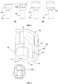
Figure 1 (Prior Art) shows a perspective view of (a) a typical screw cap for installing onto a head of a wheel screw, for example a wheel fastener, (b) another typical screw cap for installing onto a head of a wheel screw, for example a wheel fastener, and (c) a typical screw cap for installing onto a head of another wheel screw, for example an anti-theft wheel fastener; -
Figure 2 (Prior Art) shows a perspective view of (a) a known wheel fastener and (b) a known anti-theft wheel fastener that can be used with the screw cap of the present invention; -
Figure 3 shows a side view of (a) a wheel fastener and an anti-theft wheel fastener prior to installation of a screw cap of the present invention and (b) the wheel fastener and anti-theft wheel fastener of (a) after installation of a screw cap of the present invention; -
Figure 4 shows a cross-sectional view in perspective of a screw cap according to one example embodiment, the screw cap including a partial of an installed wheel fastener; -
Figure 5 shows another cross-sectional view of the screw cap ofFigure 4 ; and -
Figure 6 shows another cross-sectional view of the screw cap ofFigures 4 and5 , the screw cap including a representation of an installed anti-theft wheel fastener. - The described example embodiment relates to a screw cap, and in particular a screw cap which can be installed onto two different types of screw heads. More particularly, the screw cap can be installed onto both a head of a wheel fastener and a head of an-anti theft wheel fastener.
- Certain terminology is used in the following description for convenience only and is not limiting. The words 'upper' and 'lower' designate directions in the drawings to which reference is made and are with respect to the described component when assembled and mounted. The words 'inner', 'inwardly' and 'outer', 'outwardly' refer to directions toward and away from, respectively, a designated centreline or a geometric centre of an element being described (e.g. a central axis), the particular meaning being readily apparent from the context of the description. Further, the terms 'proximal' (i.e. nearer to) and 'distal' (i.e. away from) designate positions relative to a body or a point of attachment (e.g. a screw head).
- Further, as used herein, the terms 'connected', `affixed' and the like are intended to include direct connections between two members without any other members interposed therebetween, as well as, indirect connections between members in which one or more other members are interposed therebetween. The terminology includes the words specifically mentioned above, derivatives thereof, and words of similar import.
- Further, unless otherwise specified, the terms 'wheel screw', 'wheel fastener', 'screw', 'fastener' and the like may be used interchangeably. Moreover, the terms 'screw cap', 'wheel cap', 'wheel screw cap', 'wheel fastener cap' and the like may be used interchangeably.
- Further, unless otherwise specified, the use of ordinal adjectives, such as, 'first', 'second', 'third' etc. merely indicate that different instances of like objects are being referred to and are not intended to imply that the objects so described must be in a given sequence, either temporally, spatially, in ranking or in any other manner. Like reference numerals are used to depict like features throughout.
- Referring now to Figure 2(a), a screw, or a
wheel fastener 102, for example a bolt, includes a first-type screw head 102a, which is hexagonal in the depicted embodiment. Thehead 102a may have another shape in another embodiment. Thewheel fastener 102 generally includes a threaded shank extending outwardly from thehead 102a at a distal end thereof. Figure 2(b) shows another screw, or ananti-theft wheel fastener 104, for example a bolt, including a second-type screw head 104a, which is circular in the depicted embodiment. Theanti-theft wheel fastener 104 generally includes a threaded shank extending outwardly from thehead 104a at a distal end thereof. - The first-
type screw head 102a and the second-type screw head 104a are different. Thehead 104a includes a cut-out 104b for engaging with a corresponding tool key (not shown) in use, thereby allowing the user to install or remove theanti-theft wheel fastener 104. Thehead 104a and the cut-out 104b may have another shape in another embodiment. Thewheel fastener 102 and theanti-theft wheel fastener 104, or indeed other appropriate screw means having any other appropriate shape or size, may be used with the screw cap of the present invention. - As shown in
Figure 3(a) , thehead 102a of the wheel fastener 102 (i.e. wheel screw) may have a greater height than that of thehead 104a of the anti-theft wheel fastener 104 (i.e. anti-theft screw). The difference between the height of eachfastener Figure 3(a) . In use, ascrew cap 100 according to the invention, is placed over thehead fastener respective fastener screw cap 100 to thefasteners Figure 3(b) . Thescrew cap 100 may generally be a push-fit or a friction-fit with respect to therespective fastener screw cap 100 is configured to accommodate the difference in height, diameter or shape of theheads fasteners screw cap 100 provides a standardized visual appearance, as shown inFigure 3(b) . - Referring to
Figures 4 to 6 , thescrew cap 100 includes a generallytubular body 106 having aside wall 108. Thebody 106 of the present example is shown as a generally round tubular shape, but other shapes are contemplated in other embodiments. Thebody 106 includes anend wall 110 at a first, distal,end portion 130 and anopening 112 at a second, proximal,end portion 132. Theproximal end portion 132 is generally formed at one end of a centre axis A, and thedistal end portion 130 is generally formed to the other end of the centre axis A. In use, theend wall 110 is the outermost portion of thescrew cap 100, i.e. furthest away from the screw head, after installation. - The
body 106 includes a first coupling member including a plurality of first surroundingwall members 114. Additionally, thescrew cap 100 includes a generally cylindricalupstanding wall 122 located proximal the centre axis A of thescrew cap 100 and internally of the first surroundingwall members 114. Theupstanding wall 122 may be any shape. Theupstanding wall 122 extends towards theopen end 112 of thebody 106 from theend wall 110. Theupstanding wall 122 and the first surroundingwall members 114 generally define a substantially annularly shaped recess that is coaxial with the centre axis A of thebody 106. Further, theupstanding wall 122 generally encloses, and defines, acentral bore 124 within theend wall 110. Thecentral bore 124 may be arranged to receive a corresponding tool key. Thecentral bore 124 provided within theend wall 110 may be any appropriate shape. Indeed, thecentral bore 124 may not be provided in some embodiments, such that theend wall 110 forms a closed end of thescrew cap 100. - The plurality of first surrounding
I wall members 114 are arranged generally concentrically and facing theupstanding wall 122 thereby forming the substantially annularly shaped recess. In the depicted example, six first surroundingwall members 114 provided in a hexagonal arrangement are contemplated, however any number or arrangement of surroundingwall members 114 may be used in another embodiment. For example, in another embodiment, each of the surroundingwall members 114 may be formed as a unitary, or integral, component, thus providing a single surroundingwall member 114. - The
side wall 108 of thebody 106 also includes a second coupling member including a plurality of circumferentially spaced apartrib members 118. Eachrib member 118 extends radially inwardly from an inner surface of theside wall 108 towards the centre axis A of thebody 106. The second coupling member, formed by therib members 118, is coaxial and/or concentric with respect to the first coupling member, formed by the surroundingwall members 114. In the depicted example, sixrib members 118 that are equidistantly spaced apart are contemplated, however any number or arrangement ofrib members 118 may be used in another embodiment. - Additionally, a plurality of
first shoulder members 116 connect each of the surroundingwall members 114 to arespective rib member 118. Eachfirst shoulder member 116 generally defines a stop for the second-type screw head, as discussed below. Moreover, a plurality ofsecond shoulder members 120 connect each of the surroundingwall members 114 to theupstanding wall 122. Eachsecond shoulder member 120 generally defines a stop, or provides a predetermined height, for the first-type screw head, as discussed below. In the depicted embodiment, there is provided a difference in height between thefirst shoulder members 116 and thesecond shoulder members 120. That is, thefirst shoulder members 116 provide a first predetermined height, and thesecond shoulder members 120 provide a second predetermined height, the second predetermined height being greater than the first predetermined height. The predetermined height may be measured from a respective shoulder to theopening 112 of thebody 106. In this way, thescrew cap 100 can accommodate differences in the height of wheel screw heads, as discussed below. - Referring to
Figures 2 to 6 , in use, a first-type wheel screw having a first-type screw head, for example thewheel fastener 102 as described above, is provided. Thewheel fastener head 102a is generally hexagonal in the depicted embodiment, but other shapes are contemplated in other embodiments. Thescrew cap 100 is installed over thehead 102a by pushing thescrew cap 100 onto thehead 102a. In this way thehead 102a is clamped between theupstanding wall 122 and the plurality of surrounding Iwall members 114. That is, thehead 102a is secured between theupstanding wall 122 and each of the surroundingwall members 114 by a friction-fit. - In use, a second-type wheel screw having a second-type screw head, for example an
anti-theft wheel fastener 104 as described above, is provided. The second-type wheel screw is different to the first-type wheel screw. More specifically, the first-type screw head is different to the second-type screw head. For example, the shape and height of the screw heads are different, as described in relation toFigure 3 . - The
screw cap 100 is installed over thehead 104a by pushing thescrew cap 100 onto thehead 104a. In this way, thehead 104a is clamped by the plurality ofrib members 118. That is, thehead 104a is secured by each of therib members 118 by a friction-fit. - As demonstrated in
Figures 3 to 6 , the difference in the predetermined height of theshoulders - After installation, if it is desired to remove the
screw cap 100, thescrew cap 100 is simply pulled in a direction opposition to that of the installation. More particularly, thecentral bore 124 may receive a corresponding tool key to aid removal. - The
screw cap 100 may comprise any suitable material, for example, a resilient material or a polymer material. Thescrew cap 100 may assume any appropriate shape, size, arrangement or the like. - It will be appreciated by persons skilled in the art that the above embodiment(s) have been described by way of example only and not in any limitative sense, and that various alterations and modifications are possible without departing from the scope of the invention as defined by the appended claims. Various modifications to the detailed designs as described above are possible, for example, variations may exist in shape, size, arrangement, assembly or the like.
Claims (9)
- A screw cap (100) for a screw head, comprising:a tubular body (106), having an end wall (110) at a distal end portion (130) and an opening (112) at a proximal end portion (132) along a centre axis (A);at least one first coupling member (114, 122) arranged coaxially to said centre axis (A) at said distal end portion (130), adapted to retainingly receive at least a portion of a first-type screw head (102a); andat least one second coupling member (108, 118) arranged coaxially with, and axially proximal to, said at least one first coupling member (114, 122), adapted to retainingly receive at least a portion of a second-type screw head (104a);wherein said at least one first coupling member comprises at least one first surrounding wall member (114), and at least one second radial wall member (122) arranged concentric to and facing said first surrounding wall member (114), said at least one first surrounding wall member (114) and said at least one second radial wall member (122) protruding from said end wall (110) towards said proximal end portion (132) along said centre axis (A), so as to form a substantially annularly shaped recess coaxial with said tubular body (106) and adapted to matingly receive at least a portion of the first-type screw head (102a);wherein said second coupling member comprises at least two spaced apart rib members (118), each rib member (118) extending radially inwardly from an inner surface (108) of said tubular body so as to couplingly engage with at least a portion of the second-type screw head (104a), during use; andwherein the diameter defined by the circumferentially spaced apart rib members (118) is greater than the diameter defined by the annularly shaped recess.
- A screw cap according to claim 1, wherein said substantially annularly shaped recess is configured to provide a friction fit with at least a portion of the first-type screw head (102a).
- A screw cap according to any preceding claim, wherein said at least two rib members (118) are adapted to provide a friction fit with at least a portion of the second-type screw head (104a), during use.
- A screw cap according to any preceding claim, comprising at least six circumferentially equidistantly spaced apart rib members (118).
- A screw cap according to any preceding claim, wherein the first-type screw head (102a) is a hexagonal screw head.
- A screw cap according to any preceding claim, wherein the second-type screw head (104a) is a circular screw head.
- A screw cap according to any preceding claim, wherein the screw cap (100) comprises a resilient material.
- A screw cap according to any preceding claim, wherein the screw cap (100) comprises a polymer material.
- A screw cap according to any preceding claim, wherein the end wall (110) comprises a central bore (124) adapted to receive a corresponding tool key.
Priority Applications (2)
| Application Number | Priority Date | Filing Date | Title |
|---|---|---|---|
| PCT/US2020/057671 WO2021091740A1 (en) | 2019-11-04 | 2020-10-28 | A screw cap |
| CN202080074873.0A CN114667398A (en) | 2019-11-04 | 2020-10-28 | a screw cap |
Applications Claiming Priority (1)
| Application Number | Priority Date | Filing Date | Title |
|---|---|---|---|
| EP19382959 | 2019-11-04 |
Publications (2)
| Publication Number | Publication Date |
|---|---|
| EP3816464A1 EP3816464A1 (en) | 2021-05-05 |
| EP3816464B1 true EP3816464B1 (en) | 2024-10-23 |
Family
ID=68503040
Family Applications (1)
| Application Number | Title | Priority Date | Filing Date |
|---|---|---|---|
| EP20190974.4A Active EP3816464B1 (en) | 2019-11-04 | 2020-08-13 | A screw cap |
Country Status (3)
| Country | Link |
|---|---|
| EP (1) | EP3816464B1 (en) |
| CN (1) | CN114667398A (en) |
| WO (1) | WO2021091740A1 (en) |
Families Citing this family (1)
| Publication number | Priority date | Publication date | Assignee | Title |
|---|---|---|---|---|
| CN116292575B (en) * | 2023-05-19 | 2023-08-22 | 福建省华盖机械制造有限公司 | High-sealing stable nut and production device thereof |
Family Cites Families (12)
| Publication number | Priority date | Publication date | Assignee | Title |
|---|---|---|---|---|
| US6293744B1 (en) * | 2000-06-14 | 2001-09-25 | Illinois Tool Works Inc. | Fastener system including a fastener and a cap |
| GB0127734D0 (en) * | 2001-11-20 | 2002-01-09 | Itw Ltd | Fastening Element |
| JP2003278732A (en) * | 2002-03-22 | 2003-10-02 | Itabashi Yohin Seisakusho:Kk | Cap for wheel nut |
| CN101344111A (en) * | 2007-07-09 | 2009-01-14 | 协永产业株式会社 | Lock nut |
| JP3138476U (en) * | 2007-07-09 | 2008-01-10 | 協永産業株式会社 | Lock nut |
| EP3106683B1 (en) * | 2015-06-18 | 2019-04-10 | Bulten AB | A fastener |
| US9879711B2 (en) * | 2016-06-16 | 2018-01-30 | Honda Motor Co., Ltd. | Wheel bolt cap |
| US10087974B2 (en) * | 2016-12-06 | 2018-10-02 | David Szymczak | Protection cap assembly for one or more bolts |
| FR3067769B1 (en) * | 2017-06-15 | 2019-07-19 | Lisi Aerospace | POSITIVE LOCK FASTENING |
| FR3067768B1 (en) * | 2017-06-15 | 2019-07-19 | Lisi Aerospace | POSITIVE LOCK FASTENING |
| JP6666325B2 (en) * | 2017-12-15 | 2020-03-13 | 日本ボデーパーツ工業株式会社 | Nut cap |
| US20190234448A1 (en) * | 2018-01-26 | 2019-08-01 | Illinois Tool Works Inc. | Compression limiting fastening system |
-
2020
- 2020-08-13 EP EP20190974.4A patent/EP3816464B1/en active Active
- 2020-10-28 CN CN202080074873.0A patent/CN114667398A/en active Pending
- 2020-10-28 WO PCT/US2020/057671 patent/WO2021091740A1/en not_active Ceased
Also Published As
| Publication number | Publication date |
|---|---|
| EP3816464A1 (en) | 2021-05-05 |
| CN114667398A (en) | 2022-06-24 |
| WO2021091740A1 (en) | 2021-05-14 |
Similar Documents
| Publication | Publication Date | Title |
|---|---|---|
| US7351020B1 (en) | High security fastener constructions | |
| US11339821B2 (en) | High security fastener with external shroud retainer | |
| US2076789A (en) | Wheel | |
| US5707113A (en) | Wheel cover assembly for a vehicle wheel | |
| EP0692641A2 (en) | Device for connecting parts having holes with different centre-to-centre distances | |
| US20190113065A1 (en) | Tamper-resistant fastener for connecting a wheel rim to a hub flange of a motor vehicle | |
| CA1159095A (en) | Wheel cover mounting bracket | |
| US6070946A (en) | Dual wheel mounting system | |
| US4961611A (en) | Vehicle wheel cover | |
| EP3816464B1 (en) | A screw cap | |
| EP1680286B1 (en) | Arrangement and method for mounting a wheel cap on a vehicle | |
| EP3056748B1 (en) | Locking device made as a nut or bolt | |
| US6036419A (en) | Fastener structure | |
| EP1741568B1 (en) | Wheel cover retention means | |
| JPH021681B2 (en) | ||
| EP3963218B1 (en) | An arrangement with a clip for connecting a cover panel to a vehicle body, and a vehicle | |
| EP3628507B1 (en) | An antitheft locking device for the wheel of a vehicle | |
| EP3283304B1 (en) | Antitheft locking device for vehicle wheels | |
| US4046481A (en) | Gland nut retaining means | |
| EP3006746B1 (en) | Integrated fastener for plastic components | |
| US20060181139A1 (en) | Wheel nut and cap assembly | |
| EP3748173B1 (en) | Fastening device made as a nut or a bolt provided with a plug | |
| EP3670939A1 (en) | Fastening device provided with a rotatable washer | |
| EP3495173B1 (en) | Tire valve cap | |
| AU2018355420B2 (en) | Wheel retention system |
Legal Events
| Date | Code | Title | Description |
|---|---|---|---|
| PUAI | Public reference made under article 153(3) epc to a published international application that has entered the european phase |
Free format text: ORIGINAL CODE: 0009012 |
|
| STAA | Information on the status of an ep patent application or granted ep patent |
Free format text: STATUS: THE APPLICATION HAS BEEN PUBLISHED |
|
| AK | Designated contracting states |
Kind code of ref document: A1 Designated state(s): AL AT BE BG CH CY CZ DE DK EE ES FI FR GB GR HR HU IE IS IT LI LT LU LV MC MK MT NL NO PL PT RO RS SE SI SK SM TR |
|
| STAA | Information on the status of an ep patent application or granted ep patent |
Free format text: STATUS: REQUEST FOR EXAMINATION WAS MADE |
|
| 17P | Request for examination filed |
Effective date: 20211102 |
|
| RBV | Designated contracting states (corrected) |
Designated state(s): AL AT BE BG CH CY CZ DE DK EE ES FI FR GB GR HR HU IE IS IT LI LT LU LV MC MK MT NL NO PL PT RO RS SE SI SK SM TR |
|
| STAA | Information on the status of an ep patent application or granted ep patent |
Free format text: STATUS: EXAMINATION IS IN PROGRESS |
|
| 17Q | First examination report despatched |
Effective date: 20230406 |
|
| GRAP | Despatch of communication of intention to grant a patent |
Free format text: ORIGINAL CODE: EPIDOSNIGR1 |
|
| STAA | Information on the status of an ep patent application or granted ep patent |
Free format text: STATUS: GRANT OF PATENT IS INTENDED |
|
| INTG | Intention to grant announced |
Effective date: 20240618 |
|
| GRAS | Grant fee paid |
Free format text: ORIGINAL CODE: EPIDOSNIGR3 |
|
| GRAA | (expected) grant |
Free format text: ORIGINAL CODE: 0009210 |
|
| STAA | Information on the status of an ep patent application or granted ep patent |
Free format text: STATUS: THE PATENT HAS BEEN GRANTED |
|
| AK | Designated contracting states |
Kind code of ref document: B1 Designated state(s): AL AT BE BG CH CY CZ DE DK EE ES FI FR GB GR HR HU IE IS IT LI LT LU LV MC MK MT NL NO PL PT RO RS SE SI SK SM TR |
|
| REG | Reference to a national code |
Ref country code: GB Ref legal event code: FG4D |
|
| REG | Reference to a national code |
Ref country code: CH Ref legal event code: EP |
|
| P01 | Opt-out of the competence of the unified patent court (upc) registered |
Free format text: CASE NUMBER: APP_53092/2024 Effective date: 20240923 |
|
| REG | Reference to a national code |
Ref country code: DE Ref legal event code: R096 Ref document number: 602020039801 Country of ref document: DE |
|
| REG | Reference to a national code |
Ref country code: IE Ref legal event code: FG4D |
|
| REG | Reference to a national code |
Ref country code: LT Ref legal event code: MG9D |
|
| REG | Reference to a national code |
Ref country code: NL Ref legal event code: MP Effective date: 20241023 |
|
| REG | Reference to a national code |
Ref country code: AT Ref legal event code: MK05 Ref document number: 1735052 Country of ref document: AT Kind code of ref document: T Effective date: 20241023 |
|
| PG25 | Lapsed in a contracting state [announced via postgrant information from national office to epo] |
Ref country code: NL Free format text: LAPSE BECAUSE OF FAILURE TO SUBMIT A TRANSLATION OF THE DESCRIPTION OR TO PAY THE FEE WITHIN THE PRESCRIBED TIME-LIMIT Effective date: 20241023 |
|
| PG25 | Lapsed in a contracting state [announced via postgrant information from national office to epo] |
Ref country code: NL Free format text: LAPSE BECAUSE OF FAILURE TO SUBMIT A TRANSLATION OF THE DESCRIPTION OR TO PAY THE FEE WITHIN THE PRESCRIBED TIME-LIMIT Effective date: 20241023 |
|
| PG25 | Lapsed in a contracting state [announced via postgrant information from national office to epo] |
Ref country code: HR Free format text: LAPSE BECAUSE OF FAILURE TO SUBMIT A TRANSLATION OF THE DESCRIPTION OR TO PAY THE FEE WITHIN THE PRESCRIBED TIME-LIMIT Effective date: 20241023 Ref country code: IS Free format text: LAPSE BECAUSE OF FAILURE TO SUBMIT A TRANSLATION OF THE DESCRIPTION OR TO PAY THE FEE WITHIN THE PRESCRIBED TIME-LIMIT Effective date: 20250223 Ref country code: PT Free format text: LAPSE BECAUSE OF FAILURE TO SUBMIT A TRANSLATION OF THE DESCRIPTION OR TO PAY THE FEE WITHIN THE PRESCRIBED TIME-LIMIT Effective date: 20250224 |
|
| PG25 | Lapsed in a contracting state [announced via postgrant information from national office to epo] |
Ref country code: FI Free format text: LAPSE BECAUSE OF FAILURE TO SUBMIT A TRANSLATION OF THE DESCRIPTION OR TO PAY THE FEE WITHIN THE PRESCRIBED TIME-LIMIT Effective date: 20241023 |
|
| PG25 | Lapsed in a contracting state [announced via postgrant information from national office to epo] |
Ref country code: BG Free format text: LAPSE BECAUSE OF FAILURE TO SUBMIT A TRANSLATION OF THE DESCRIPTION OR TO PAY THE FEE WITHIN THE PRESCRIBED TIME-LIMIT Effective date: 20241023 |
|
| PG25 | Lapsed in a contracting state [announced via postgrant information from national office to epo] |
Ref country code: ES Free format text: LAPSE BECAUSE OF FAILURE TO SUBMIT A TRANSLATION OF THE DESCRIPTION OR TO PAY THE FEE WITHIN THE PRESCRIBED TIME-LIMIT Effective date: 20241023 |
|
| PG25 | Lapsed in a contracting state [announced via postgrant information from national office to epo] |
Ref country code: NO Free format text: LAPSE BECAUSE OF FAILURE TO SUBMIT A TRANSLATION OF THE DESCRIPTION OR TO PAY THE FEE WITHIN THE PRESCRIBED TIME-LIMIT Effective date: 20250123 |
|
| PG25 | Lapsed in a contracting state [announced via postgrant information from national office to epo] |
Ref country code: LV Free format text: LAPSE BECAUSE OF FAILURE TO SUBMIT A TRANSLATION OF THE DESCRIPTION OR TO PAY THE FEE WITHIN THE PRESCRIBED TIME-LIMIT Effective date: 20241023 Ref country code: AT Free format text: LAPSE BECAUSE OF FAILURE TO SUBMIT A TRANSLATION OF THE DESCRIPTION OR TO PAY THE FEE WITHIN THE PRESCRIBED TIME-LIMIT Effective date: 20241023 Ref country code: GR Free format text: LAPSE BECAUSE OF FAILURE TO SUBMIT A TRANSLATION OF THE DESCRIPTION OR TO PAY THE FEE WITHIN THE PRESCRIBED TIME-LIMIT Effective date: 20250124 |
|
| PG25 | Lapsed in a contracting state [announced via postgrant information from national office to epo] |
Ref country code: PL Free format text: LAPSE BECAUSE OF FAILURE TO SUBMIT A TRANSLATION OF THE DESCRIPTION OR TO PAY THE FEE WITHIN THE PRESCRIBED TIME-LIMIT Effective date: 20241023 |
|
| PG25 | Lapsed in a contracting state [announced via postgrant information from national office to epo] |
Ref country code: RS Free format text: LAPSE BECAUSE OF FAILURE TO SUBMIT A TRANSLATION OF THE DESCRIPTION OR TO PAY THE FEE WITHIN THE PRESCRIBED TIME-LIMIT Effective date: 20250123 |
|
| PG25 | Lapsed in a contracting state [announced via postgrant information from national office to epo] |
Ref country code: SM Free format text: LAPSE BECAUSE OF FAILURE TO SUBMIT A TRANSLATION OF THE DESCRIPTION OR TO PAY THE FEE WITHIN THE PRESCRIBED TIME-LIMIT Effective date: 20241023 |
|
| PG25 | Lapsed in a contracting state [announced via postgrant information from national office to epo] |
Ref country code: DK Free format text: LAPSE BECAUSE OF FAILURE TO SUBMIT A TRANSLATION OF THE DESCRIPTION OR TO PAY THE FEE WITHIN THE PRESCRIBED TIME-LIMIT Effective date: 20241023 |
|
| PG25 | Lapsed in a contracting state [announced via postgrant information from national office to epo] |
Ref country code: EE Free format text: LAPSE BECAUSE OF FAILURE TO SUBMIT A TRANSLATION OF THE DESCRIPTION OR TO PAY THE FEE WITHIN THE PRESCRIBED TIME-LIMIT Effective date: 20241023 |
|
| PG25 | Lapsed in a contracting state [announced via postgrant information from national office to epo] |
Ref country code: RO Free format text: LAPSE BECAUSE OF FAILURE TO SUBMIT A TRANSLATION OF THE DESCRIPTION OR TO PAY THE FEE WITHIN THE PRESCRIBED TIME-LIMIT Effective date: 20241023 |
|
| REG | Reference to a national code |
Ref country code: DE Ref legal event code: R097 Ref document number: 602020039801 Country of ref document: DE |
|
| PG25 | Lapsed in a contracting state [announced via postgrant information from national office to epo] |
Ref country code: SK Free format text: LAPSE BECAUSE OF FAILURE TO SUBMIT A TRANSLATION OF THE DESCRIPTION OR TO PAY THE FEE WITHIN THE PRESCRIBED TIME-LIMIT Effective date: 20241023 |
|
| PG25 | Lapsed in a contracting state [announced via postgrant information from national office to epo] |
Ref country code: CZ Free format text: LAPSE BECAUSE OF FAILURE TO SUBMIT A TRANSLATION OF THE DESCRIPTION OR TO PAY THE FEE WITHIN THE PRESCRIBED TIME-LIMIT Effective date: 20241023 |
|
| PG25 | Lapsed in a contracting state [announced via postgrant information from national office to epo] |
Ref country code: IT Free format text: LAPSE BECAUSE OF FAILURE TO SUBMIT A TRANSLATION OF THE DESCRIPTION OR TO PAY THE FEE WITHIN THE PRESCRIBED TIME-LIMIT Effective date: 20241023 |
|
| PLBE | No opposition filed within time limit |
Free format text: ORIGINAL CODE: 0009261 |
|
| STAA | Information on the status of an ep patent application or granted ep patent |
Free format text: STATUS: NO OPPOSITION FILED WITHIN TIME LIMIT |
|
| PG25 | Lapsed in a contracting state [announced via postgrant information from national office to epo] |
Ref country code: SE Free format text: LAPSE BECAUSE OF FAILURE TO SUBMIT A TRANSLATION OF THE DESCRIPTION OR TO PAY THE FEE WITHIN THE PRESCRIBED TIME-LIMIT Effective date: 20241023 |
|
| 26N | No opposition filed |
Effective date: 20250724 |
|
| PGFP | Annual fee paid to national office [announced via postgrant information from national office to epo] |
Ref country code: DE Payment date: 20250827 Year of fee payment: 6 |
|
| REG | Reference to a national code |
Ref country code: CH Ref legal event code: H13 Free format text: ST27 STATUS EVENT CODE: U-0-0-H10-H13 (AS PROVIDED BY THE NATIONAL OFFICE) Effective date: 20260324 |
|
| PG25 | Lapsed in a contracting state [announced via postgrant information from national office to epo] |
Ref country code: MC Free format text: LAPSE BECAUSE OF FAILURE TO SUBMIT A TRANSLATION OF THE DESCRIPTION OR TO PAY THE FEE WITHIN THE PRESCRIBED TIME-LIMIT Effective date: 20241023 |
|
| PG25 | Lapsed in a contracting state [announced via postgrant information from national office to epo] |
Ref country code: LU Free format text: LAPSE BECAUSE OF NON-PAYMENT OF DUE FEES Effective date: 20250813 |
|
| PG25 | Lapsed in a contracting state [announced via postgrant information from national office to epo] |
Ref country code: CH Free format text: LAPSE BECAUSE OF NON-PAYMENT OF DUE FEES Effective date: 20250831 |