EP3816421A1 - Method of diagnosing a temperature sensor provided at a rear stage of an air filter - Google Patents
Method of diagnosing a temperature sensor provided at a rear stage of an air filter Download PDFInfo
- Publication number
- EP3816421A1 EP3816421A1 EP20152144.0A EP20152144A EP3816421A1 EP 3816421 A1 EP3816421 A1 EP 3816421A1 EP 20152144 A EP20152144 A EP 20152144A EP 3816421 A1 EP3816421 A1 EP 3816421A1
- Authority
- EP
- European Patent Office
- Prior art keywords
- temperature
- rear stage
- vehicle
- air filter
- temperature sensor
- Prior art date
- Legal status (The legal status is an assumption and is not a legal conclusion. Google has not performed a legal analysis and makes no representation as to the accuracy of the status listed.)
- Withdrawn
Links
Images

Classifications
-
- F—MECHANICAL ENGINEERING; LIGHTING; HEATING; WEAPONS; BLASTING
- F02—COMBUSTION ENGINES; HOT-GAS OR COMBUSTION-PRODUCT ENGINE PLANTS
- F02D—CONTROLLING COMBUSTION ENGINES
- F02D41/00—Electrical control of supply of combustible mixture or its constituents
- F02D41/22—Safety or indicating devices for abnormal conditions
- F02D41/222—Safety or indicating devices for abnormal conditions relating to the failure of sensors or parameter detection devices
-
- F—MECHANICAL ENGINEERING; LIGHTING; HEATING; WEAPONS; BLASTING
- F02—COMBUSTION ENGINES; HOT-GAS OR COMBUSTION-PRODUCT ENGINE PLANTS
- F02M—SUPPLYING COMBUSTION ENGINES IN GENERAL WITH COMBUSTIBLE MIXTURES OR CONSTITUENTS THEREOF
- F02M35/00—Combustion-air cleaners, air intakes, intake silencers, or induction systems specially adapted for, or arranged on, internal-combustion engines
- F02M35/10—Air intakes; Induction systems
- F02M35/10373—Sensors for intake systems
- F02M35/1038—Sensors for intake systems for temperature or pressure
-
- F—MECHANICAL ENGINEERING; LIGHTING; HEATING; WEAPONS; BLASTING
- F01—MACHINES OR ENGINES IN GENERAL; ENGINE PLANTS IN GENERAL; STEAM ENGINES
- F01N—GAS-FLOW SILENCERS OR EXHAUST APPARATUS FOR MACHINES OR ENGINES IN GENERAL; GAS-FLOW SILENCERS OR EXHAUST APPARATUS FOR INTERNAL-COMBUSTION ENGINES
- F01N11/00—Monitoring or diagnostic devices for exhaust-gas treatment apparatus
- F01N11/002—Monitoring or diagnostic devices for exhaust-gas treatment apparatus the diagnostic devices measuring or estimating temperature or pressure in, or downstream of the exhaust apparatus
-
- F—MECHANICAL ENGINEERING; LIGHTING; HEATING; WEAPONS; BLASTING
- F02—COMBUSTION ENGINES; HOT-GAS OR COMBUSTION-PRODUCT ENGINE PLANTS
- F02D—CONTROLLING COMBUSTION ENGINES
- F02D41/00—Electrical control of supply of combustible mixture or its constituents
- F02D41/02—Circuit arrangements for generating control signals
- F02D41/14—Introducing closed-loop corrections
- F02D41/1438—Introducing closed-loop corrections using means for determining characteristics of the combustion gases; Sensors therefor
- F02D41/1439—Introducing closed-loop corrections using means for determining characteristics of the combustion gases; Sensors therefor characterised by the position of the sensor
- F02D41/144—Sensor in intake manifold
-
- F—MECHANICAL ENGINEERING; LIGHTING; HEATING; WEAPONS; BLASTING
- F02—COMBUSTION ENGINES; HOT-GAS OR COMBUSTION-PRODUCT ENGINE PLANTS
- F02D—CONTROLLING COMBUSTION ENGINES
- F02D41/00—Electrical control of supply of combustible mixture or its constituents
- F02D41/02—Circuit arrangements for generating control signals
- F02D41/14—Introducing closed-loop corrections
- F02D41/1438—Introducing closed-loop corrections using means for determining characteristics of the combustion gases; Sensors therefor
- F02D41/1439—Introducing closed-loop corrections using means for determining characteristics of the combustion gases; Sensors therefor characterised by the position of the sensor
- F02D41/1441—Plural sensors
-
- F—MECHANICAL ENGINEERING; LIGHTING; HEATING; WEAPONS; BLASTING
- F02—COMBUSTION ENGINES; HOT-GAS OR COMBUSTION-PRODUCT ENGINE PLANTS
- F02M—SUPPLYING COMBUSTION ENGINES IN GENERAL WITH COMBUSTIBLE MIXTURES OR CONSTITUENTS THEREOF
- F02M35/00—Combustion-air cleaners, air intakes, intake silencers, or induction systems specially adapted for, or arranged on, internal-combustion engines
- F02M35/02—Air cleaners
- F02M35/0201—Housings; Casings; Frame constructions; Lids; Manufacturing or assembling thereof
- F02M35/0205—Details, e.g. sensors or measuring devices
-
- B—PERFORMING OPERATIONS; TRANSPORTING
- B60—VEHICLES IN GENERAL
- B60Y—INDEXING SCHEME RELATING TO ASPECTS CROSS-CUTTING VEHICLE TECHNOLOGY
- B60Y2400/00—Special features of vehicle units
- B60Y2400/30—Sensors
- B60Y2400/302—Temperature sensors
-
- F—MECHANICAL ENGINEERING; LIGHTING; HEATING; WEAPONS; BLASTING
- F02—COMBUSTION ENGINES; HOT-GAS OR COMBUSTION-PRODUCT ENGINE PLANTS
- F02D—CONTROLLING COMBUSTION ENGINES
- F02D2200/00—Input parameters for engine control
- F02D2200/02—Input parameters for engine control the parameters being related to the engine
- F02D2200/023—Temperature of lubricating oil or working fluid
-
- F—MECHANICAL ENGINEERING; LIGHTING; HEATING; WEAPONS; BLASTING
- F02—COMBUSTION ENGINES; HOT-GAS OR COMBUSTION-PRODUCT ENGINE PLANTS
- F02D—CONTROLLING COMBUSTION ENGINES
- F02D2200/00—Input parameters for engine control
- F02D2200/02—Input parameters for engine control the parameters being related to the engine
- F02D2200/04—Engine intake system parameters
- F02D2200/0414—Air temperature
-
- F—MECHANICAL ENGINEERING; LIGHTING; HEATING; WEAPONS; BLASTING
- F02—COMBUSTION ENGINES; HOT-GAS OR COMBUSTION-PRODUCT ENGINE PLANTS
- F02D—CONTROLLING COMBUSTION ENGINES
- F02D2200/00—Input parameters for engine control
- F02D2200/02—Input parameters for engine control the parameters being related to the engine
- F02D2200/10—Parameters related to the engine output, e.g. engine torque or engine speed
- F02D2200/101—Engine speed
-
- F—MECHANICAL ENGINEERING; LIGHTING; HEATING; WEAPONS; BLASTING
- F02—COMBUSTION ENGINES; HOT-GAS OR COMBUSTION-PRODUCT ENGINE PLANTS
- F02D—CONTROLLING COMBUSTION ENGINES
- F02D2200/00—Input parameters for engine control
- F02D2200/50—Input parameters for engine control said parameters being related to the vehicle or its components
- F02D2200/501—Vehicle speed
-
- F—MECHANICAL ENGINEERING; LIGHTING; HEATING; WEAPONS; BLASTING
- F02—COMBUSTION ENGINES; HOT-GAS OR COMBUSTION-PRODUCT ENGINE PLANTS
- F02D—CONTROLLING COMBUSTION ENGINES
- F02D2400/00—Control systems adapted for specific engine types; Special features of engine control systems not otherwise provided for; Power supply, connectors or cabling for engine control systems
- F02D2400/08—Redundant elements, e.g. two sensors for measuring the same parameter
-
- F—MECHANICAL ENGINEERING; LIGHTING; HEATING; WEAPONS; BLASTING
- F02—COMBUSTION ENGINES; HOT-GAS OR COMBUSTION-PRODUCT ENGINE PLANTS
- F02D—CONTROLLING COMBUSTION ENGINES
- F02D41/00—Electrical control of supply of combustible mixture or its constituents
- F02D41/02—Circuit arrangements for generating control signals
- F02D41/04—Introducing corrections for particular operating conditions
- F02D41/08—Introducing corrections for particular operating conditions for idling
-
- Y—GENERAL TAGGING OF NEW TECHNOLOGICAL DEVELOPMENTS; GENERAL TAGGING OF CROSS-SECTIONAL TECHNOLOGIES SPANNING OVER SEVERAL SECTIONS OF THE IPC; TECHNICAL SUBJECTS COVERED BY FORMER USPC CROSS-REFERENCE ART COLLECTIONS [XRACs] AND DIGESTS
- Y02—TECHNOLOGIES OR APPLICATIONS FOR MITIGATION OR ADAPTATION AGAINST CLIMATE CHANGE
- Y02T—CLIMATE CHANGE MITIGATION TECHNOLOGIES RELATED TO TRANSPORTATION
- Y02T10/00—Road transport of goods or passengers
- Y02T10/10—Internal combustion engine [ICE] based vehicles
- Y02T10/40—Engine management systems
Definitions
- Embodiments of the present disclosure relate to a method of diagnosing whether a temperature sensor provided at a rear stage of an air filter of an engine room fails.
- an exhaust gas recirculation (EGR) device has been developed and applied.
- the EGR device is a device that recirculates some of an exhaust gas, which is an inert gas, to an intake system, mixes the some of the exhaust gas with a mixed gas suctioned into the engine, and decreases a maximum temperature during combustion to reduce generation of NO x through a method of reducing NO x in the exhaust gas.
- the EGR device controls some of the exhaust gas to be recirculated to a suction line according to a driving condition by detecting an intake temperature, a temperature of cooling water, and a vehicle speed or a shift gear position under most suitable control.
- EGR technology is a system configured to obtain an exhaust gas discharged from a cylinder 10 at a rear stage of a main catalyst (not shown) and to deliver the exhaust gas to a front stage of a compressor 20. Since the delivery of the exhaust gas is performed at a lower pressure close to atmospheric pressure, a modifier of a low pressure (LP) added to the EGR technology, and thus the EGR technology is called LP-EGR technology.
- LP-EGR technology a modifier of a low pressure
- a downstream pressure of an EGR valve 31 should be formed to be smaller than an upstream pressure of the EGR valve 31. Since a pressure at the rear stage of the main catalyst and a pressure at the front stage of the compressor 20 are formed to be a relatively low pressure that is substantially the same as a level of the atmospheric pressure, there may be a case in which a pressure difference between the upstream pressure and the downstream pressure of the EGR valve 31 is not significant.
- a differential pressure valve (DPV) 32 may be applied to the front stage of the compressor 20. This is a method whereby, when a differential pressure is required, the DPV 32 is controlled in a closing direction thereof to form a negative pressure at the front stage of the compressor 20.
- An undescribed reference numeral 33 denotes a throttle valve.
- the MAF temperature sensor 41 should undergo failure diagnosis in accordance with North American on-board diagnostics (OBD) regulations.
- OBD North American on-board diagnostics
- the EGR system should be used only when a corresponding value is reasonably usable.
- a temperature sensor such as the MAF temperature sensor 41 is not used. Therefore, there is no need to separately implement a failure diagnosis logic.
- An embodiment of the present disclosure is directed to a method of diagnosing whether a temperature sensor provided at a rear stage of an air filter of an engine room fails.
- a method of diagnosing a temperature sensor provided at a rear stage of an air filter includes comparing a heating condition factor, which is calculated with a weight according to whether heat is generated inside an engine room, with a factor threshold. The method includes, when the heating condition factor is less than the factor threshold, calculating a deviation between a temperature of an intake manifold, which is measured by an intake manifold temperature sensor, with a temperature of intake air at a rear stage of an air filter, which is measured by an intake air temperature sensor provided at the rear stage of the air filter. The method includes comparing a temperature threshold with the deviation between the temperature of the intake manifold and the temperature of the intake air at the rear stage of the air filter. The method also includes, when the deviation between the temperature of the intake manifold and the temperature of the intake air at the rear stage of the air filter exceeds the temperature threshold, diagnosing the intake air temperature sensor provided at the rear stage of the air filter as failing.
- the intake manifold temperature sensor may be a temperature sensor inside a manifold absolute pressure (MAP) sensor.
- MAP manifold absolute pressure
- MAF mass air flow
- the method may further include determining whether a vehicle is idling.
- the heating condition factor may be increased or decreased according to whether the vehicle is idling.
- the method may further include increasing the heating condition factor according to a revolutions per minute (RPM) of an engine.
- RPM revolutions per minute
- the method may further include decreasing the heating condition factor according to a vehicle speed.
- the method may further include determining whether an operating condition of a diagnostic logic is satisfied while the vehicle is driving.
- the operating condition of the diagnostic logic may include that the vehicle speed exceeds a vehicle speed setting value, a flow rate through a throttle valve exceeds a flow rate setting value, and/or a cooling water temperature of engine cooling water exceeds a water temperature setting value.
- the calculation of the deviation between the temperature of the intake manifold and the temperature of the intake air at the rear stage of the air filter may include storing and updating a maximum value and a minimum value of the deviation between the temperature of the intake manifold and the temperature of the intake air at the rear stage of the air filter.
- a method of diagnosing a temperature sensor provided at a rear stage of an air filter includes determining whether a vehicle is idling. The method includes, when the vehicle is determined as idling through the determination of whether the vehicle is idling, increasing a heating condition factor according to an RPM of an engine. The method includes, when the vehicle is determined as not idling through the determination of whether the vehicle is idling, decreasing the heating condition factor according to a vehicle speed. The method includes comparing a heating condition factor, which is increased or decreased with a weight according to whether heat is generated inside an engine compartment, with a factor threshold.
- the method includes, when the heating condition factor is less than the factor threshold, calculating a deviation between a temperature of an intake manifold, which is measured by an intake manifold temperature sensor, and a temperature of intake air at a rear stage of an air filter, which is measured by an intake air temperature sensor provided at the rear stage of the air filter.
- the method includes comparing a temperature threshold with the deviation between the temperature of the intake manifold and the temperature of the intake air at the rear stage of the air filter.
- the method also includes, when the deviation between the temperature of the intake manifold and the temperature of the intake air at the rear stage of the air filter exceeds the temperature threshold, diagnosing the intake air temperature sensor provided at the rear stage of the air filter as failing.
- the intake manifold temperature sensor may be a temperature sensor inside a MAP sensor.
- the intake air temperature sensor provided at the rear stage of the air filter may be a temperature sensor inside a MAF sensor.
- the method may further include determining whether an operating condition of a diagnostic logic is satisfied while the vehicle is driving.
- the operating condition of the diagnostic logic may include that the vehicle speed exceeds a vehicle speed setting value, a flow rate through a throttle valve exceeds a flow rate setting value, and/or a cooling water temperature of engine cooling water exceeds a water temperature setting value.
- the calculation of the deviation between the temperature of the intake manifold and the temperature of the intake air at the rear stage of the air filter may include storing and updating a maximum value and a minimum value of the deviation between the temperature of the intake manifold and the temperature of the intake air at the rear stage of the air filter.
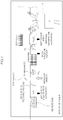
- FIG. 1 is a diagram illustrating an intake system to which a method of diagnosing a temperature sensor provided at a rear stage of an air filter according to the present disclosure is applied.
- FIG. 2 is a graph showing a temperature deviation and a heating condition factor due to a vehicle speed.
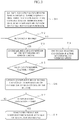
- FIG. 3 is a diagram illustrating a flowchart of a method of diagnosing a temperature sensor provided at a rear stage of an air filter according to the present disclosure.
- FIGS. 1-3 a method of diagnosing a temperature sensor provided at a rear stage of an air filter according to one embodiment of the present disclosure is described with reference to FIGS. 1-3 .
- the present disclosure is a method for diagnosing whether an intake air temperature sensor 41 (mass air flow (MAF) temperature sensor) provided at a rear stage of an air filter 50 fails in a system to which an exhaust gas recirculation (EGR) device is applied.
- an intake air temperature sensor 41 mass air flow (MAF) temperature sensor
- EGR exhaust gas recirculation
- the intake air temperature sensor 41 provided at the rear stage of the air filter 50 is a temperature sensor, which is constituted inside a MAF sensor.
- a temperature at the rear stage of the air filter 50 is a temperature measured at a position at which outside air is introduced into an engine compartment.
- the temperature is measured as a certain value between a temperature of the outside air and a temperature of the engine compartment.
- the present disclosure proposes a method of performing diagnosis by directly comparing measured ambient temperatures instead of a separate temperature model.
- MAP manifold absolute pressure
- the present disclosure proposes a method of defining a time point at which failure diagnosis is possible through a comparison between temperature sensors inside the engine compartment to be capable of diagnosing a failure at the corresponding time point.
- the temperature inside the engine compartment has a high correlation with the vehicle speed.
- a temperature of an intake manifold temperature sensor 42 relatively close to the engine is higher than that of the intake air temperature sensor 41 provided at the rear stage of the air filter 50.
- tendencies of the temperatures are very similar to each other.
- an intake manifold is cooled due to a driving wind such that a difference between the temperatures is not significantly increased. Therefore, when the vehicle is driving at speed, a constant offset may be applied for comparison and failure diagnosis.
- a temperature difference between the two temperature sensors 41 and 42 is significantly increased.
- a heating condition factor of a temperature of the engine compartment is defined.
- the heating condition factor is defined to diagnose a failure by comparing temperatures of the two temperature sensors 41 and 42 only when the heating condition factor does not exceed a threshold.
- the heating condition factor is increased based on a revolutions per minute (RPM) of the engine. That is, an amount of heating may be varied according to the RPM of the engine so that a weight of an increment is applied based on the RPM of the engine.
- RPM revolutions per minute
- the heating condition factor is decreased based on the vehicle speed. That is, an amount of cooling may be varied according to the vehicle speed so that a weight of a decrement is applied based on the vehicle speed.
- the threshold of the corresponding factor is selected in an environment in which a deviation between the two sensors 41 and 42 is small, and diagnosis is set to be possible at only a value less than the threshold.
- the corresponding operating condition includes that: the vehicle speed should be greater than a vehicle speed setting value; a throttle flow rate should be greater than a flow rate setting value; and a cooling water temperature of engine cooling water is higher than a water temperature setting value so that the engine should warm up.
- the intake manifold temperature sensor 42 should be in a normal condition.
- a heating condition factor is increased according to an RPM of the engine (S13).
- the heating condition factor is decreased according to the vehicle speed (S14).
- the deviation between the temperature of the intake manifold and the temperature of the intake air at the rear stage of the air filter 50 is calculated through S16 to update a maximum value and a minimum value, and, when the calculated deviation exceeds the temperature threshold, the intake air temperature sensor 41 is diagnosed as failing.
- the method diagnoses whether a temperature sensor provided at a rear stage of an air filter has failed under predetermined conditions such that it is possible to diagnose the OBD.
Landscapes
- Engineering & Computer Science (AREA)
- Chemical & Material Sciences (AREA)
- Combustion & Propulsion (AREA)
- Mechanical Engineering (AREA)
- General Engineering & Computer Science (AREA)
- Analytical Chemistry (AREA)
- Manufacturing & Machinery (AREA)
- Chemical Kinetics & Catalysis (AREA)
- Combined Controls Of Internal Combustion Engines (AREA)
Abstract
Description
- Embodiments of the present disclosure relate to a method of diagnosing whether a temperature sensor provided at a rear stage of an air filter of an engine room fails.
- Recently, in order to improve fuel efficiency of an engine of a vehicle, an exhaust gas recirculation (EGR) device has been developed and applied.
- The EGR device is a device that recirculates some of an exhaust gas, which is an inert gas, to an intake system, mixes the some of the exhaust gas with a mixed gas suctioned into the engine, and decreases a maximum temperature during combustion to reduce generation of NOx through a method of reducing NOx in the exhaust gas.
- Further, in order to secure driving ability, the EGR device controls some of the exhaust gas to be recirculated to a suction line according to a driving condition by detecting an intake temperature, a temperature of cooling water, and a vehicle speed or a shift gear position under most suitable control.
- In other words, referring to
FIG. 1 , EGR technology is a system configured to obtain an exhaust gas discharged from acylinder 10 at a rear stage of a main catalyst (not shown) and to deliver the exhaust gas to a front stage of acompressor 20. Since the delivery of the exhaust gas is performed at a lower pressure close to atmospheric pressure, a modifier of a low pressure (LP) added to the EGR technology, and thus the EGR technology is called LP-EGR technology. - Further, in order to deliver a large amount of the exhaust gas through the EGR device in the LP-EGR system, a downstream pressure of an
EGR valve 31 should be formed to be smaller than an upstream pressure of theEGR valve 31. Since a pressure at the rear stage of the main catalyst and a pressure at the front stage of thecompressor 20 are formed to be a relatively low pressure that is substantially the same as a level of the atmospheric pressure, there may be a case in which a pressure difference between the upstream pressure and the downstream pressure of theEGR valve 31 is not significant. - Thus, in this case, in order to form the downstream pressure to be low to generate a differential pressure, a differential pressure valve (DPV) 32 may be applied to the front stage of the
compressor 20. This is a method whereby, when a differential pressure is required, theDPV 32 is controlled in a closing direction thereof to form a negative pressure at the front stage of thecompressor 20. - An
undescribed reference numeral 33 denotes a throttle valve. - In such an LP-EGR system, in order to determine whether the use of EGR is available, condensate calculation is performed and a measured temperature value of air before joining to the EGR is used as a physical value for calculating condensate through a mass air flow (MAF)
temperature sensor 41. - Further, the
MAF temperature sensor 41 should undergo failure diagnosis in accordance with North American on-board diagnostics (OBD) regulations. The EGR system should be used only when a corresponding value is reasonably usable. - According to a related art, since there is no need to refer to a temperature value at a rear stage of the
air filter 50, a temperature sensor such as theMAF temperature sensor 41 is not used. Therefore, there is no need to separately implement a failure diagnosis logic. - The contents described in the above Description of the Related Art are to help understand the background of the present disclosure. Thus, this section may include what is not previously known to a person of ordinary skill in the art to which the present disclosure pertains.
- An embodiment of the present disclosure is directed to a method of diagnosing whether a temperature sensor provided at a rear stage of an air filter of an engine room fails.
- Other objects and advantages of the present disclosure can be understood by the following description and should become apparent with reference to the embodiments of the present disclosure. Also, it should be evident to those having ordinary skill in the art to which the present disclosure pertains that the objects and advantages of the present disclosure can be realized by the embodiments as claimed and combinations thereof.
- In accordance with an embodiment of the present disclosure, a method of diagnosing a temperature sensor provided at a rear stage of an air filter is provided. The method includes comparing a heating condition factor, which is calculated with a weight according to whether heat is generated inside an engine room, with a factor threshold. The method includes, when the heating condition factor is less than the factor threshold, calculating a deviation between a temperature of an intake manifold, which is measured by an intake manifold temperature sensor, with a temperature of intake air at a rear stage of an air filter, which is measured by an intake air temperature sensor provided at the rear stage of the air filter. The method includes comparing a temperature threshold with the deviation between the temperature of the intake manifold and the temperature of the intake air at the rear stage of the air filter. The method also includes, when the deviation between the temperature of the intake manifold and the temperature of the intake air at the rear stage of the air filter exceeds the temperature threshold, diagnosing the intake air temperature sensor provided at the rear stage of the air filter as failing.
- The intake manifold temperature sensor may be a temperature sensor inside a manifold absolute pressure (MAP) sensor. The intake air temperature sensor provided at the rear stage of the air filter may be a temperature sensor inside a mass air flow (MAF) sensor.
- Further, before the comparing of the heating condition factor with the factor threshold, the method may further include determining whether a vehicle is idling. The heating condition factor may be increased or decreased according to whether the vehicle is idling.
- When the vehicle is determined as idling through the determination of whether the vehicle is idling, the method may further include increasing the heating condition factor according to a revolutions per minute (RPM) of an engine.
- Alternatively, when the vehicle is determined as not idling through the determination of whether the vehicle is idling, the method may further include decreasing the heating condition factor according to a vehicle speed.
- Further, before the determination of whether the vehicle is idling, the method may further include determining whether an operating condition of a diagnostic logic is satisfied while the vehicle is driving.
- The operating condition of the diagnostic logic may include that the vehicle speed exceeds a vehicle speed setting value, a flow rate through a throttle valve exceeds a flow rate setting value, and/or a cooling water temperature of engine cooling water exceeds a water temperature setting value.
- The calculation of the deviation between the temperature of the intake manifold and the temperature of the intake air at the rear stage of the air filter may include storing and updating a maximum value and a minimum value of the deviation between the temperature of the intake manifold and the temperature of the intake air at the rear stage of the air filter.
- In accordance with another embodiment of the present disclosure, a method of diagnosing a temperature sensor provided at a rear stage of an air filter is provided. The method includes determining whether a vehicle is idling. The method includes, when the vehicle is determined as idling through the determination of whether the vehicle is idling, increasing a heating condition factor according to an RPM of an engine. The method includes, when the vehicle is determined as not idling through the determination of whether the vehicle is idling, decreasing the heating condition factor according to a vehicle speed. The method includes comparing a heating condition factor, which is increased or decreased with a weight according to whether heat is generated inside an engine compartment, with a factor threshold. The method includes, when the heating condition factor is less than the factor threshold, calculating a deviation between a temperature of an intake manifold, which is measured by an intake manifold temperature sensor, and a temperature of intake air at a rear stage of an air filter, which is measured by an intake air temperature sensor provided at the rear stage of the air filter. The method includes comparing a temperature threshold with the deviation between the temperature of the intake manifold and the temperature of the intake air at the rear stage of the air filter. The method also includes, when the deviation between the temperature of the intake manifold and the temperature of the intake air at the rear stage of the air filter exceeds the temperature threshold, diagnosing the intake air temperature sensor provided at the rear stage of the air filter as failing.
- The intake manifold temperature sensor may be a temperature sensor inside a MAP sensor. The intake air temperature sensor provided at the rear stage of the air filter may be a temperature sensor inside a MAF sensor.
- Further, before the determination of whether the vehicle is idling, the method may further include determining whether an operating condition of a diagnostic logic is satisfied while the vehicle is driving. The operating condition of the diagnostic logic may include that the vehicle speed exceeds a vehicle speed setting value, a flow rate through a throttle valve exceeds a flow rate setting value, and/or a cooling water temperature of engine cooling water exceeds a water temperature setting value.
- Further, the calculation of the deviation between the temperature of the intake manifold and the temperature of the intake air at the rear stage of the air filter may include storing and updating a maximum value and a minimum value of the deviation between the temperature of the intake manifold and the temperature of the intake air at the rear stage of the air filter.
-
-
FIG. 1 is a diagram illustrating an intake system to which a method of diagnosing a temperature sensor provided at a rear stage of an air filter according to the present disclosure is applied. -
FIG. 2 is a graph showing a temperature deviation and a heating condition factor due to a vehicle speed. -
FIG. 3 is a diagram illustrating a flowchart of a method of diagnosing a temperature sensor provided at a rear stage of an air filter according to the present disclosure. - Reference should be made to the accompanying drawings, which illustrate embodiments of the present disclosure, and to the description in the accompanying drawings in order to fully understand the present disclosure, operational advantages of the present disclosure, and objects attained by practicing the present disclosure.
- In the description of embodiments of the present disclosure, known technologies or repetitive descriptions, which unnecessarily obscure the gist of the present disclosure may have been reduced or omitted.
-
FIG. 1 is a diagram illustrating an intake system to which a method of diagnosing a temperature sensor provided at a rear stage of an air filter according to the present disclosure is applied.FIG. 2 is a graph showing a temperature deviation and a heating condition factor due to a vehicle speed. - Further,
FIG. 3 is a diagram illustrating a flowchart of a method of diagnosing a temperature sensor provided at a rear stage of an air filter according to the present disclosure. - Hereinafter, a method of diagnosing a temperature sensor provided at a rear stage of an air filter according to one embodiment of the present disclosure is described with reference to
FIGS. 1-3 . - The present disclosure is a method for diagnosing whether an intake air temperature sensor 41 (mass air flow (MAF) temperature sensor) provided at a rear stage of an
air filter 50 fails in a system to which an exhaust gas recirculation (EGR) device is applied. - The intake
air temperature sensor 41 provided at the rear stage of theair filter 50 is a temperature sensor, which is constituted inside a MAF sensor. - A temperature at the rear stage of the
air filter 50 is a temperature measured at a position at which outside air is introduced into an engine compartment. Thus, the temperature is measured as a certain value between a temperature of the outside air and a temperature of the engine compartment. - There is a method of calculating the temperature at the corresponding position through an accurate physical model. However, in terms of minimizing inaccuracy of a model and unnecessary calculation, the present disclosure proposes a method of performing diagnosis by directly comparing measured ambient temperatures instead of a separate temperature model.
- In other words, among temperature sensors applied to the existing system, another temperature sensor capable of representing a temperature inside the engine compartment is a temperature sensor embedded in an intake air pressure sensor (manifold absolute pressure (MAP) sensor).
- However, considering a physical distance from the intake
air temperature sensor 41 provided at the rear stage of theair filter 50 and a distance from a heating element inside the engine, a temperature value of a corresponding position does not always exhibit a similar tendency. - Therefore, the present disclosure proposes a method of defining a time point at which failure diagnosis is possible through a comparison between temperature sensors inside the engine compartment to be capable of diagnosing a failure at the corresponding time point.
- To this end, a correlation between a temperature inside the engine compartment and a vehicle speed is described with reference to
FIG. 2 . The temperature inside the engine compartment has a high correlation with the vehicle speed. - In other words, a temperature of an intake manifold temperature sensor 42 relatively close to the engine is higher than that of the intake
air temperature sensor 41 provided at the rear stage of theair filter 50. However, when a vehicle speed is present, tendencies of the temperatures are very similar to each other. When the vehicle is moving at speed, an intake manifold is cooled due to a driving wind such that a difference between the temperatures is not significantly increased. Therefore, when the vehicle is driving at speed, a constant offset may be applied for comparison and failure diagnosis. However, when the vehicle is in a stop state, since a driving wind which cools the temperature of the intake manifold is not present, a temperature difference between the twotemperature sensors 41 and 42 is significantly increased. - Therefore, a heating condition factor of a temperature of the engine compartment is defined. The heating condition factor is defined to diagnose a failure by comparing temperatures of the two
temperature sensors 41 and 42 only when the heating condition factor does not exceed a threshold. When the vehicle is stopped and idling, the heating condition factor is increased based on a revolutions per minute (RPM) of the engine. That is, an amount of heating may be varied according to the RPM of the engine so that a weight of an increment is applied based on the RPM of the engine. - Further, when the vehicle is being driven at speed, the heating condition factor is decreased based on the vehicle speed. That is, an amount of cooling may be varied according to the vehicle speed so that a weight of a decrement is applied based on the vehicle speed.
- Therefore, the threshold of the corresponding factor is selected in an environment in which a deviation between the two
sensors 41 and 42 is small, and diagnosis is set to be possible at only a value less than the threshold. - Referring to
FIG. 3 , when an operating condition of a diagnostic logic is satisfied while a vehicle is driving (S11), a process of the present disclosure starts. - The corresponding operating condition includes that: the vehicle speed should be greater than a vehicle speed setting value; a throttle flow rate should be greater than a flow rate setting value; and a cooling water temperature of engine cooling water is higher than a water temperature setting value so that the engine should warm up.
- Further, the intake manifold temperature sensor 42 should be in a normal condition.
- Next, whether the vehicle is idling is determined (S 12).
- According to the determination result of whether the vehicle is idling, when the vehicle is idling, a heating condition factor is increased according to an RPM of the engine (S13).
- Otherwise, when the vehicle is driving in a partially loaded state, the heating condition factor is decreased according to the vehicle speed (S14).
- As described above, after the heating condition factor is increased or decreased according to the situation, it is determined whether the heating condition factor is less than a factor threshold (S15).
- In the present disclosure, it is possible, only in the situation in which the heating condition factor is less than the factor threshold, to compare a temperature due to the intake manifold temperature sensor 42 with a temperature of intake air at the rear stage of the
air filter 50 due to the intakeair temperature sensor 41. When the condition of S15 is satisfied, an absolute value of a difference between a temperature of the intake manifold and a temperature of the intake air at the rear stage of theair filter 50 is calculated and updated (S16). - Then, whether a temperature deviation calculated in S16 exceeds a temperature threshold is determined (S 17). When the temperature deviation exceeds the temperature threshold, the intake air temperature sensor 41 (MAF sensor) provided at the rear stage of the
air filter 50 is diagnosed as failing (S18). - That is, the deviation between the temperature of the intake manifold and the temperature of the intake air at the rear stage of the
air filter 50 is calculated through S16 to update a maximum value and a minimum value, and, when the calculated deviation exceeds the temperature threshold, the intakeair temperature sensor 41 is diagnosed as failing. - As described above, in accordance with the present disclosure, whether the temperature sensor provided at the rear stage of the air filter fails is diagnosed under predetermined conditions such that it is possible to diagnose OBD and perform a more accurate condensate calculation using a corresponding sensor. Consequently, accurate calculation of a condensate flow rate allows EGR to be used in wide areas. Thus, fuel efficiency can be improved.
- In accordance with a method of diagnosing a temperature sensor provided at a rear stage of an air filter according to the present disclosure, the method diagnoses whether a temperature sensor provided at a rear stage of an air filter has failed under predetermined conditions such that it is possible to diagnose the OBD.
- Therefore, it is possible to perform a more accurate condensate calculation using a corresponding sensor. Consequently, accurate calculation of a condensate flow rate allows EGR to be used in wide areas. Thus, fuel efficiency can be improved.
- While the present disclosure has been described with respect to the specific embodiments, it should be apparent to those having ordinary skill in the art that various changes and modifications may be made without departing from the spirit and scope of the present disclosure as defined in the following claims. Accordingly, it should be noted that such alterations or modifications fall within the claims of the present disclosure, and the scope of the present disclosure should be construed on the basis of the appended claims.
Claims (14)
- A method of diagnosing a temperature sensor provided at a rear stage of an air filter, the method comprising:comparing a heating condition factor, which is calculated with a weight according to whether heat is generated inside an engine compartment, with a factor threshold;when the heating condition factor is less than the factor threshold, calculating a deviation between a temperature of an intake manifold, which is measured by an intake manifold temperature sensor, and a temperature of intake air at a rear stage of an air filter, which is measured by an intake air temperature sensor provided at the rear stage of the air filter;comparing a temperature threshold with the deviation between the temperature of the intake manifold and the temperature of the intake air at the rear stage of the air filter; andwhen the deviation between the temperature of the intake manifold and the temperature of the intake air at the rear stage of the air filter exceeds the temperature threshold, diagnosing the intake air temperature sensor provided at the rear stage of the air filter as failing.
- The method of claim 1, wherein the intake manifold temperature sensor includes a temperature sensor inside a manifold absolute pressure (MAP) sensor, and the intake air temperature sensor provided at the rear stage of the air filter includes a temperature sensor inside a mass air flow (MAF) sensor.
- The method of claim 1 or 2, further comprising:before the comparing of the heating condition factor with the factor threshold, determining whether a vehicle is idling,wherein the heating condition factor is increased or decreased according to the determination of whether the vehicle is idling.
- The method of claim 3, further comprising:
when the vehicle is determined as idling through the determination of whether the vehicle is idling, increasing the heating condition factor according to a revolutions per minute (RPM) of an engine. - The method of claim 3, further comprising:
when the vehicle is determined as not idling through the determination of whether the vehicle is idling, decreasing the heating condition factor according to a vehicle speed. - The method of any one of claims 3 to 5, further comprising:
before the determination of whether the vehicle is idling, determining whether an operating condition of a diagnostic logic is satisfied while the vehicle is driving. - The method of claim 6, wherein the operating condition of a diagnostic logic includes that the vehicle speed exceeds a vehicle speed setting value, a flow rate through a throttle valve exceeds a flow rate setting value, and a cooling water temperature of engine cooling water exceeds a water temperature setting value.
- The method of claim 5, further comprising:
before the determination of whether the vehicle is idling, determining whether an operating condition of a diagnostic logic is satisfied while the vehicle is driving. - The method of claim 8, wherein the operating condition of a diagnostic logic includes that the vehicle speed exceeds a vehicle speed setting value, a flow rate through a throttle valve exceeds a flow rate setting value, and a cooling water temperature of engine cooling water exceeds a water temperature setting value.
- The method of any one of claims 1 to 9, wherein the calculation of the deviation between the temperature of the intake manifold and the temperature of the intake air at the rear stage of the air filter includes storing and updating a maximum value and a minimum value of the deviation between the temperature of the intake manifold and the temperature of the intake air at the rear stage of the air filter.
- A method of diagnosing a temperature sensor provided at a rear stage of an air filter, the method comprising:.
determining whether a vehicle is idling;
when the vehicle is determined as idling through the determination of whether the vehicle is idling, increasing a heating condition factor according to a revolution per minute (RPM) of an engine;
when the vehicle is determined as not idling through the determination of whether the vehicle is idling, decreasing the heating condition factor according to a vehicle speed;
comparing a heating condition factor, which is increased or decreased with a weight according to whether heat is generated inside an engine compartment, with a factor threshold;
when the heating condition factor is less than the factor threshold, calculating a deviation between a temperature of an intake manifold, which is measured by an intake manifold temperature sensor, and a temperature of intake air at a rear stage of an air filter, which is measured by an intake air temperature sensor provided at the rear stage of the air filter;
comparing a temperature threshold with the deviation between the temperature of the intake manifold and the temperature of the intake air at the rear stage of the air filter; and
when the deviation between the temperature of the intake manifold and the temperature of the intake air at the rear stage of the air filter exceeds the temperature threshold, diagnosing the intake air temperature sensor provided at the rear stage of the air filter as failing. - The method of claim 11, wherein the intake manifold temperature sensor includes a temperature sensor inside a manifold absolute pressure (MAP) sensor, and the intake air temperature sensor provided at the rear stage of the air filter includes a temperature sensor inside a mass air flow (MAF) sensor.
- The method of claim 11 or 12, further comprising:before the determination of whether the vehicle is idling, determining whether an operating condition of a diagnostic logic is satisfied while the vehicle is driving,wherein the operating condition of the diagnostic logic includes that the vehicle speed exceeds a vehicle speed setting value, a flow rate through a throttle valve exceeds a flow rate setting value, and a cooling water temperature of engine cooling water exceeds a water temperature setting value.
- The method of any one of claims 11 to 13, further comprising:
the calculation of the deviation between the temperature of the intake manifold and the temperature of the intake air at the rear stage of the air filter includes storing and updating a maximum value and a minimum value of the deviation between the temperature of the intake manifold and the temperature of the intake air at the rear stage of the air filter.
Applications Claiming Priority (1)
| Application Number | Priority Date | Filing Date | Title |
|---|---|---|---|
| KR1020190138501A KR20210052908A (en) | 2019-11-01 | 2019-11-01 | Diagnose method of an air flow sensor after an air filter |
Publications (1)
| Publication Number | Publication Date |
|---|---|
| EP3816421A1 true EP3816421A1 (en) | 2021-05-05 |
Family
ID=69174353
Family Applications (1)
| Application Number | Title | Priority Date | Filing Date |
|---|---|---|---|
| EP20152144.0A Withdrawn EP3816421A1 (en) | 2019-11-01 | 2020-01-16 | Method of diagnosing a temperature sensor provided at a rear stage of an air filter |
Country Status (4)
| Country | Link |
|---|---|
| US (1) | US11248568B2 (en) |
| EP (1) | EP3816421A1 (en) |
| KR (1) | KR20210052908A (en) |
| CN (1) | CN112780393A (en) |
Citations (4)
| Publication number | Priority date | Publication date | Assignee | Title |
|---|---|---|---|---|
| JPH09303191A (en) * | 1996-05-14 | 1997-11-25 | Toyota Motor Corp | Abnormality diagnosis device for intake air temperature sensor for internal combustion engine |
| DE102007018623B3 (en) * | 2007-04-19 | 2008-09-11 | Continental Automotive Gmbh | Method for functional testing of a temperature sensor of an internal combustion engine |
| JP2010138796A (en) * | 2008-12-11 | 2010-06-24 | Toyota Motor Corp | Malfunction diagnosis device for intake air temperature sensor |
| EP2375044A1 (en) * | 2008-12-25 | 2011-10-12 | Hino Motors Ltd. | Apparatus for detecting abnormality of sensor |
Family Cites Families (8)
| Publication number | Priority date | Publication date | Assignee | Title |
|---|---|---|---|---|
| US7120535B2 (en) * | 2005-01-14 | 2006-10-10 | Delphi Technologies, Inc. | Method and apparatus to evaluate an intake air temperature monitoring circuit |
| JP5531776B2 (en) * | 2010-05-24 | 2014-06-25 | 日産自動車株式会社 | Temperature sensor failure diagnosis device |
| JP5883289B2 (en) * | 2011-12-22 | 2016-03-09 | 日野自動車株式会社 | Anomaly detection method |
| JP5897403B2 (en) * | 2012-05-25 | 2016-03-30 | 日野自動車株式会社 | Anomaly detection method |
| WO2014069243A1 (en) * | 2012-11-05 | 2014-05-08 | 日産自動車株式会社 | Device and method for diagnosing fault in intake temperature sensor |
| KR101355621B1 (en) | 2012-12-14 | 2014-01-27 | 기아자동차주식회사 | Egr system |
| JP6146192B2 (en) * | 2013-07-31 | 2017-06-14 | いすゞ自動車株式会社 | Diagnostic equipment |
| JP6559291B1 (en) * | 2018-04-25 | 2019-08-14 | 本田技研工業株式会社 | Abnormality detection system for intake air cooling system of internal combustion engine |
-
2019
- 2019-11-01 KR KR1020190138501A patent/KR20210052908A/en not_active Abandoned
-
2020
- 2020-01-16 EP EP20152144.0A patent/EP3816421A1/en not_active Withdrawn
- 2020-01-20 US US16/747,224 patent/US11248568B2/en not_active Expired - Fee Related
- 2020-02-03 CN CN202010079171.3A patent/CN112780393A/en not_active Withdrawn
Patent Citations (4)
| Publication number | Priority date | Publication date | Assignee | Title |
|---|---|---|---|---|
| JPH09303191A (en) * | 1996-05-14 | 1997-11-25 | Toyota Motor Corp | Abnormality diagnosis device for intake air temperature sensor for internal combustion engine |
| DE102007018623B3 (en) * | 2007-04-19 | 2008-09-11 | Continental Automotive Gmbh | Method for functional testing of a temperature sensor of an internal combustion engine |
| JP2010138796A (en) * | 2008-12-11 | 2010-06-24 | Toyota Motor Corp | Malfunction diagnosis device for intake air temperature sensor |
| EP2375044A1 (en) * | 2008-12-25 | 2011-10-12 | Hino Motors Ltd. | Apparatus for detecting abnormality of sensor |
Also Published As
| Publication number | Publication date |
|---|---|
| KR20210052908A (en) | 2021-05-11 |
| US20210131391A1 (en) | 2021-05-06 |
| US11248568B2 (en) | 2022-02-15 |
| CN112780393A (en) | 2021-05-11 |
Similar Documents
| Publication | Publication Date | Title |
|---|---|---|
| US9976503B2 (en) | Method for estimating charge air cooler condensation storage and/or release with an intake oxygen sensor | |
| US8608374B2 (en) | Outside air temperature sensor diagnostic systems for a vehicle | |
| US9732690B2 (en) | Method for estimating charge air cooler condensation storage and/or release with two intake oxygen sensors | |
| US9243553B2 (en) | Electric waste gate control system sensor calibration with end-stop detection | |
| US9903265B2 (en) | Method for estimating charge air cooler condensation storage with an intake oxygen sensor | |
| CN106246377B (en) | Method for leak detection of crankcase ventilation systems | |
| US6862878B2 (en) | Method and device for operating an internal combustion engine | |
| US9267464B2 (en) | Method and system for vacuum generation | |
| JP6304296B2 (en) | Engine control device | |
| WO2019214821A1 (en) | An egr flow determination method, an egr rate error determination method, a control method for an internal combustion engine, and an internal combustion engine | |
| US10927794B2 (en) | Active canister purge system and diagnostic method thereof | |
| US10428750B2 (en) | Turbocharged internal combustion engine system | |
| JP6486523B1 (en) | Engine system | |
| GB2482323A (en) | A method and system for controlling an engine based on determination of rotational speed of a compressor | |
| US9926936B2 (en) | Variable discharge compressor control | |
| JP5538712B2 (en) | EGR device for internal combustion engine | |
| JP2011001822A (en) | Electrically controlled throttle characteristic learning control device and method therefor | |
| US11248568B2 (en) | Method of diagnosing a temperature sensor provided at a rear stage of an air filter | |
| US10391999B2 (en) | Control apparatus for diesel engine | |
| JP4365342B2 (en) | Turbocharger abnormality determination device | |
| US11274637B1 (en) | Methods and systems for EGR system | |
| JP2001159574A (en) | Diagnosis device for pressure sensor | |
| US10125704B2 (en) | Engine system having EGR apparatus | |
| SE534364C2 (en) | Method and computer program for adapting an air flow sensor in a vehicle engine | |
| CN117212004A (en) | Method and system for an EGR system |
Legal Events
| Date | Code | Title | Description |
|---|---|---|---|
| PUAI | Public reference made under article 153(3) epc to a published international application that has entered the european phase |
Free format text: ORIGINAL CODE: 0009012 |
|
| STAA | Information on the status of an ep patent application or granted ep patent |
Free format text: STATUS: REQUEST FOR EXAMINATION WAS MADE |
|
| 17P | Request for examination filed |
Effective date: 20201124 |
|
| AK | Designated contracting states |
Kind code of ref document: A1 Designated state(s): AL AT BE BG CH CY CZ DE DK EE ES FI FR GB GR HR HU IE IS IT LI LT LU LV MC MK MT NL NO PL PT RO RS SE SI SK SM TR |
|
| RAP3 | Party data changed (applicant data changed or rights of an application transferred) |
Owner name: HYUNDAI MOTOR COMPANY Owner name: KIA CORPORATION |
|
| STAA | Information on the status of an ep patent application or granted ep patent |
Free format text: STATUS: EXAMINATION IS IN PROGRESS |
|
| 17Q | First examination report despatched |
Effective date: 20220712 |
|
| P01 | Opt-out of the competence of the unified patent court (upc) registered |
Effective date: 20230530 |
|
| GRAP | Despatch of communication of intention to grant a patent |
Free format text: ORIGINAL CODE: EPIDOSNIGR1 |
|
| STAA | Information on the status of an ep patent application or granted ep patent |
Free format text: STATUS: GRANT OF PATENT IS INTENDED |
|
| INTG | Intention to grant announced |
Effective date: 20240221 |
|
| STAA | Information on the status of an ep patent application or granted ep patent |
Free format text: STATUS: THE APPLICATION IS DEEMED TO BE WITHDRAWN |
|
| 18D | Application deemed to be withdrawn |
Effective date: 20240622 |