EP3816411A1 - Flanged integral piston bearing - Google Patents
Flanged integral piston bearing Download PDFInfo
- Publication number
- EP3816411A1 EP3816411A1 EP20205187.6A EP20205187A EP3816411A1 EP 3816411 A1 EP3816411 A1 EP 3816411A1 EP 20205187 A EP20205187 A EP 20205187A EP 3816411 A1 EP3816411 A1 EP 3816411A1
- Authority
- EP
- European Patent Office
- Prior art keywords
- bearing
- engine
- gas turbine
- oil
- turbine engine
- Prior art date
- Legal status (The legal status is an assumption and is not a legal conclusion. Google has not performed a legal analysis and makes no representation as to the accuracy of the status listed.)
- Granted
Links
Images



Classifications
-
- F—MECHANICAL ENGINEERING; LIGHTING; HEATING; WEAPONS; BLASTING
- F01—MACHINES OR ENGINES IN GENERAL; ENGINE PLANTS IN GENERAL; STEAM ENGINES
- F01D—NON-POSITIVE DISPLACEMENT MACHINES OR ENGINES, e.g. STEAM TURBINES
- F01D25/00—Component parts, details, or accessories, not provided for in, or of interest apart from, other groups
- F01D25/16—Arrangement of bearings; Supporting or mounting bearings in casings
- F01D25/162—Bearing supports
-
- F—MECHANICAL ENGINEERING; LIGHTING; HEATING; WEAPONS; BLASTING
- F01—MACHINES OR ENGINES IN GENERAL; ENGINE PLANTS IN GENERAL; STEAM ENGINES
- F01D—NON-POSITIVE DISPLACEMENT MACHINES OR ENGINES, e.g. STEAM TURBINES
- F01D25/00—Component parts, details, or accessories, not provided for in, or of interest apart from, other groups
- F01D25/16—Arrangement of bearings; Supporting or mounting bearings in casings
-
- F—MECHANICAL ENGINEERING; LIGHTING; HEATING; WEAPONS; BLASTING
- F16—ENGINEERING ELEMENTS AND UNITS; GENERAL MEASURES FOR PRODUCING AND MAINTAINING EFFECTIVE FUNCTIONING OF MACHINES OR INSTALLATIONS; THERMAL INSULATION IN GENERAL
- F16C—SHAFTS; FLEXIBLE SHAFTS; ELEMENTS OR CRANKSHAFT MECHANISMS; ROTARY BODIES OTHER THAN GEARING ELEMENTS; BEARINGS
- F16C19/00—Bearings with rolling contact, for exclusively rotary movement
- F16C19/02—Bearings with rolling contact, for exclusively rotary movement with bearing balls essentially of the same size in one or more circular rows
- F16C19/04—Bearings with rolling contact, for exclusively rotary movement with bearing balls essentially of the same size in one or more circular rows for radial load mainly
- F16C19/08—Bearings with rolling contact, for exclusively rotary movement with bearing balls essentially of the same size in one or more circular rows for radial load mainly with two or more rows of balls
-
- F—MECHANICAL ENGINEERING; LIGHTING; HEATING; WEAPONS; BLASTING
- F16—ENGINEERING ELEMENTS AND UNITS; GENERAL MEASURES FOR PRODUCING AND MAINTAINING EFFECTIVE FUNCTIONING OF MACHINES OR INSTALLATIONS; THERMAL INSULATION IN GENERAL
- F16C—SHAFTS; FLEXIBLE SHAFTS; ELEMENTS OR CRANKSHAFT MECHANISMS; ROTARY BODIES OTHER THAN GEARING ELEMENTS; BEARINGS
- F16C19/00—Bearings with rolling contact, for exclusively rotary movement
- F16C19/02—Bearings with rolling contact, for exclusively rotary movement with bearing balls essentially of the same size in one or more circular rows
- F16C19/14—Bearings with rolling contact, for exclusively rotary movement with bearing balls essentially of the same size in one or more circular rows for both radial and axial load
- F16C19/18—Bearings with rolling contact, for exclusively rotary movement with bearing balls essentially of the same size in one or more circular rows for both radial and axial load with two or more rows of balls
- F16C19/181—Bearings with rolling contact, for exclusively rotary movement with bearing balls essentially of the same size in one or more circular rows for both radial and axial load with two or more rows of balls with angular contact
- F16C19/182—Bearings with rolling contact, for exclusively rotary movement with bearing balls essentially of the same size in one or more circular rows for both radial and axial load with two or more rows of balls with angular contact in tandem arrangement
-
- F—MECHANICAL ENGINEERING; LIGHTING; HEATING; WEAPONS; BLASTING
- F16—ENGINEERING ELEMENTS AND UNITS; GENERAL MEASURES FOR PRODUCING AND MAINTAINING EFFECTIVE FUNCTIONING OF MACHINES OR INSTALLATIONS; THERMAL INSULATION IN GENERAL
- F16C—SHAFTS; FLEXIBLE SHAFTS; ELEMENTS OR CRANKSHAFT MECHANISMS; ROTARY BODIES OTHER THAN GEARING ELEMENTS; BEARINGS
- F16C19/00—Bearings with rolling contact, for exclusively rotary movement
- F16C19/54—Systems consisting of a plurality of bearings with rolling friction
-
- F—MECHANICAL ENGINEERING; LIGHTING; HEATING; WEAPONS; BLASTING
- F16—ENGINEERING ELEMENTS AND UNITS; GENERAL MEASURES FOR PRODUCING AND MAINTAINING EFFECTIVE FUNCTIONING OF MACHINES OR INSTALLATIONS; THERMAL INSULATION IN GENERAL
- F16C—SHAFTS; FLEXIBLE SHAFTS; ELEMENTS OR CRANKSHAFT MECHANISMS; ROTARY BODIES OTHER THAN GEARING ELEMENTS; BEARINGS
- F16C25/00—Bearings for exclusively rotary movement adjustable for wear or play
- F16C25/06—Ball or roller bearings
- F16C25/08—Ball or roller bearings self-adjusting
-
- F—MECHANICAL ENGINEERING; LIGHTING; HEATING; WEAPONS; BLASTING
- F16—ENGINEERING ELEMENTS AND UNITS; GENERAL MEASURES FOR PRODUCING AND MAINTAINING EFFECTIVE FUNCTIONING OF MACHINES OR INSTALLATIONS; THERMAL INSULATION IN GENERAL
- F16C—SHAFTS; FLEXIBLE SHAFTS; ELEMENTS OR CRANKSHAFT MECHANISMS; ROTARY BODIES OTHER THAN GEARING ELEMENTS; BEARINGS
- F16C25/00—Bearings for exclusively rotary movement adjustable for wear or play
- F16C25/06—Ball or roller bearings
- F16C25/08—Ball or roller bearings self-adjusting
- F16C25/083—Ball or roller bearings self-adjusting with resilient means acting axially on a race ring to preload the bearing
-
- F—MECHANICAL ENGINEERING; LIGHTING; HEATING; WEAPONS; BLASTING
- F05—INDEXING SCHEMES RELATING TO ENGINES OR PUMPS IN VARIOUS SUBCLASSES OF CLASSES F01-F04
- F05D—INDEXING SCHEME FOR ASPECTS RELATING TO NON-POSITIVE-DISPLACEMENT MACHINES OR ENGINES, GAS-TURBINES OR JET-PROPULSION PLANTS
- F05D2220/00—Application
- F05D2220/30—Application in turbines
- F05D2220/32—Application in turbines in gas turbines
- F05D2220/323—Application in turbines in gas turbines for aircraft propulsion, e.g. jet engines
-
- F—MECHANICAL ENGINEERING; LIGHTING; HEATING; WEAPONS; BLASTING
- F05—INDEXING SCHEMES RELATING TO ENGINES OR PUMPS IN VARIOUS SUBCLASSES OF CLASSES F01-F04
- F05D—INDEXING SCHEME FOR ASPECTS RELATING TO NON-POSITIVE-DISPLACEMENT MACHINES OR ENGINES, GAS-TURBINES OR JET-PROPULSION PLANTS
- F05D2220/00—Application
- F05D2220/30—Application in turbines
- F05D2220/32—Application in turbines in gas turbines
- F05D2220/329—Application in turbines in gas turbines in helicopters
-
- F—MECHANICAL ENGINEERING; LIGHTING; HEATING; WEAPONS; BLASTING
- F05—INDEXING SCHEMES RELATING TO ENGINES OR PUMPS IN VARIOUS SUBCLASSES OF CLASSES F01-F04
- F05D—INDEXING SCHEME FOR ASPECTS RELATING TO NON-POSITIVE-DISPLACEMENT MACHINES OR ENGINES, GAS-TURBINES OR JET-PROPULSION PLANTS
- F05D2240/00—Components
- F05D2240/50—Bearings
- F05D2240/52—Axial thrust bearings
-
- F—MECHANICAL ENGINEERING; LIGHTING; HEATING; WEAPONS; BLASTING
- F05—INDEXING SCHEMES RELATING TO ENGINES OR PUMPS IN VARIOUS SUBCLASSES OF CLASSES F01-F04
- F05D—INDEXING SCHEME FOR ASPECTS RELATING TO NON-POSITIVE-DISPLACEMENT MACHINES OR ENGINES, GAS-TURBINES OR JET-PROPULSION PLANTS
- F05D2240/00—Components
- F05D2240/50—Bearings
- F05D2240/54—Radial bearings
-
- F—MECHANICAL ENGINEERING; LIGHTING; HEATING; WEAPONS; BLASTING
- F05—INDEXING SCHEMES RELATING TO ENGINES OR PUMPS IN VARIOUS SUBCLASSES OF CLASSES F01-F04
- F05D—INDEXING SCHEME FOR ASPECTS RELATING TO NON-POSITIVE-DISPLACEMENT MACHINES OR ENGINES, GAS-TURBINES OR JET-PROPULSION PLANTS
- F05D2260/00—Function
- F05D2260/15—Load balancing
-
- F—MECHANICAL ENGINEERING; LIGHTING; HEATING; WEAPONS; BLASTING
- F05—INDEXING SCHEMES RELATING TO ENGINES OR PUMPS IN VARIOUS SUBCLASSES OF CLASSES F01-F04
- F05D—INDEXING SCHEME FOR ASPECTS RELATING TO NON-POSITIVE-DISPLACEMENT MACHINES OR ENGINES, GAS-TURBINES OR JET-PROPULSION PLANTS
- F05D2270/00—Control
- F05D2270/01—Purpose of the control system
- F05D2270/09—Purpose of the control system to cope with emergencies
- F05D2270/093—Purpose of the control system to cope with emergencies of one engine in a multi-engine system
-
- F—MECHANICAL ENGINEERING; LIGHTING; HEATING; WEAPONS; BLASTING
- F16—ENGINEERING ELEMENTS AND UNITS; GENERAL MEASURES FOR PRODUCING AND MAINTAINING EFFECTIVE FUNCTIONING OF MACHINES OR INSTALLATIONS; THERMAL INSULATION IN GENERAL
- F16C—SHAFTS; FLEXIBLE SHAFTS; ELEMENTS OR CRANKSHAFT MECHANISMS; ROTARY BODIES OTHER THAN GEARING ELEMENTS; BEARINGS
- F16C2360/00—Engines or pumps
- F16C2360/23—Gas turbine engines
-
- F—MECHANICAL ENGINEERING; LIGHTING; HEATING; WEAPONS; BLASTING
- F16—ENGINEERING ELEMENTS AND UNITS; GENERAL MEASURES FOR PRODUCING AND MAINTAINING EFFECTIVE FUNCTIONING OF MACHINES OR INSTALLATIONS; THERMAL INSULATION IN GENERAL
- F16C—SHAFTS; FLEXIBLE SHAFTS; ELEMENTS OR CRANKSHAFT MECHANISMS; ROTARY BODIES OTHER THAN GEARING ELEMENTS; BEARINGS
- F16C33/00—Parts of bearings; Special methods for making bearings or parts thereof
- F16C33/30—Parts of ball or roller bearings
- F16C33/66—Special parts or details in view of lubrication
- F16C33/6637—Special parts or details in view of lubrication with liquid lubricant
-
- Y—GENERAL TAGGING OF NEW TECHNOLOGICAL DEVELOPMENTS; GENERAL TAGGING OF CROSS-SECTIONAL TECHNOLOGIES SPANNING OVER SEVERAL SECTIONS OF THE IPC; TECHNICAL SUBJECTS COVERED BY FORMER USPC CROSS-REFERENCE ART COLLECTIONS [XRACs] AND DIGESTS
- Y02—TECHNOLOGIES OR APPLICATIONS FOR MITIGATION OR ADAPTATION AGAINST CLIMATE CHANGE
- Y02T—CLIMATE CHANGE MITIGATION TECHNOLOGIES RELATED TO TRANSPORTATION
- Y02T50/00—Aeronautics or air transport
- Y02T50/60—Efficient propulsion technologies, e.g. for aircraft
-
- Y—GENERAL TAGGING OF NEW TECHNOLOGICAL DEVELOPMENTS; GENERAL TAGGING OF CROSS-SECTIONAL TECHNOLOGIES SPANNING OVER SEVERAL SECTIONS OF THE IPC; TECHNICAL SUBJECTS COVERED BY FORMER USPC CROSS-REFERENCE ART COLLECTIONS [XRACs] AND DIGESTS
- Y10—TECHNICAL SUBJECTS COVERED BY FORMER USPC
- Y10T—TECHNICAL SUBJECTS COVERED BY FORMER US CLASSIFICATION
- Y10T29/00—Metal working
- Y10T29/49—Method of mechanical manufacture
- Y10T29/49826—Assembling or joining
- Y10T29/49904—Assembling a subassembly, then assembling with a second subassembly
Definitions
- the disclosure relates generally to multi-engine aircraft and methods of operating same, and more particularly to operation of an aircraft propulsion gas turbine engine in a multi-engine aircraft.
- two or more propulsion gas turbine engines may be provided to drive a main rotor via a common gearbox, and each of the engines is sized to provide power greater than what is required for cruising using both/all engines. It can however be desirable to operate one of the engines at a very low power output (e.g. "standby" condition) during cruise, in order to reduce fuel consumption of this engine.
- a very low power output e.g. "standby" condition
- a method of operating a gas turbine engine of a multi-engine aircraft comprising: limiting motive power supplied to the aircraft by the gas turbine engine by operating the gas turbine engine in a standby mode; and when the gas turbine engine is operating in the standby mode, using an oil piston integrated in the bearing supporting the engine shaft of the gas turbine engine to generate an axial preload force on the bearing.
- the method as described above and herein may further include, in whole or in part, and in any combination, one or more of the following steps and/or features.
- the method comprises operating another gas turbine engine of the multi-engine aircraft in an active mode to supply a larger amount of motive power to the aircraft than the gas turbine engine operated in the standby mode.
- the gas turbine engines drive a common load, wherein operating one of the gas turbine engine in the standby mode supplies none of a required motive power to the common load, while the gas turbine engine in the active mode supplies all of the required motive power to the common load.
- the method comprises using the oil piston includes supplying pressurized oil into a piston cavity of the bearing assembly from an oil supply of the gas turbine engine.
- the oil piston is integrated in an outer race of the bearing, wherein using the oil piston includes applying the axial preload force on a flange of the outer race of the bearing.
- the method comprises using the oil piston includes biasing axially an inner race of the bearing against a shoulder defined on the engine shaft to load the engine shaft in a direction of the axial preload force.
- the method comprises using the oil piston includes supplying pressurized oil at a constant pressure on the outer race of the bearing to generate the axial preload force.
- the bearing of the bearing assembly is a first bearing, the bearing assembly including a second bearing, the first and second bearings mounted in a tandem configuration, the method comprising maintaining a fixed distance between the first and the second bearing in the tandem configuration while applying the axial preload force.
- the method comprises using the oil piston includes applying the axial preload force on the first bearing and the second bearing in a rearward load direction along the engine shaft.
- first and second bearings each have an inner race axially secured to the engine shaft, wherein applying the axial preload force on the first and second bearings in the rearward load direction includes biasing the engine shaft in the rearward load direction to compensate for a lack of aerodynamic load on the engine shaft.
- a method of providing a preload force on a bearing of a bearing assembly, the bearing supporting a shaft in a gas turbine engine comprising: using an oil piston integrated into a flange of the bearing to apply an axial force on an outer race of the bearing, the axial force being applied continuously on the bearing during operation of the gas turbine engine.
- the method as described above and herein may further include, in whole or in part, and in any combination, one or more of the following steps and/or features.
- the method comprises using the oil piston includes supplying pressurized oil at a constant pressure on the flange of the bearing.
- the flange at least partially circumscribes a piston cavity, the method comprising adjusting an oil pressure exerted on the flange to a desired pressure via an oil valve fluidly connected upstream of the piston cavity.
- the bearing is a first bearing
- the bearing assembly includes a second bearing mounted in a tandem configuration with the first bearing
- using the oil piston includes biasing the first and the second bearings in a rearward load direction along a rotation axis of the gas turbine engine.
- the method comprises applying the axial force on the outer race includes biasing axially an inner race of the bearing via rolling elements of the bearing interfacing between the outer race and the inner race against a complementary shoulder of the engine shaft to load the engine shaft in a rearward load direction along a rotation axis of the gas turbine engine.
- a bearing assembly for supporting an engine shaft, comprising: a bearing having an inner race, an outer race and a series of rolling elements disposed between the inner race and the outer race, the inner race of the bearing coupled to the engine shaft, the outer race of the bearing defining a flange; and an oil piston integrated into the bearing flange, the oil piston including a piston cavity, the bearing flange at least partially circumscribing the piston cavity, the oil piston configured to apply an axial preload force against the rolling elements of the bearing and in turn to the engine shaft coupled to the bearing inner race.
- the bearing assembly as described above and herein may further include, in whole or in part, and in any combination, one or more of the following features.
- the bearing has rolling elements interfacing between the outer race and an inner race, the flange being axially offset from the rolling elements, the flange extending radially outward from the rolling elements.
- the bearing is a first bearing
- the bearing assembly comprising a second bearing, the second bearing mounted to the engine shaft, the first bearing and the second bearing each having an inner race, the inner races of the first and second bearings axially secured to the engine shaft and contacting each other.
- the first bearing and the second bearing each have an inner race
- the engine shaft defining a shoulder
- the inner race of the first bearing abutting against the shoulder
- the inner race of the second bearing abutting against the inner race of the first bearing.
- the inner races of the first and second bearing are clamped on each other between the shoulder and an axial fastener engaging the engine shaft.
- Fig. 1 depicts an exemplary multi-engine aircraft 1, such as a helicopter.
- the aircraft 1 may however also be a multi-engine fixed-wing aircraft.
- the aircraft 1 includes at least two gas turbine engines 2 and 3 that may be interconnected by a common gearbox 4 to form a multi-engine drive system 5 as shown in Fig. 2 .
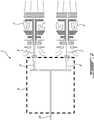
- Fig. 2 illustrates a schematic representation of an exemplary multi-engine system 5 that may be used as a power plant for the aircraft 1.
- the multi-engine system 5 comprises two or more gas turbine engines 2, 3.
- the multi-engine system 5 may be used in marine or industrial applications.
- the multi-engine system 5 of Fig. 2 includes main and reserve turboshaft gas turbine engines 2, 3 each having an engine shaft 6, 7 that are interconnected by a connector shaft 8, 9 of the common gearbox 4 to drive a common load shaft 10.
- the common load shaft 10 may drive a rotary wing 20 of a rotary-wing aircraft.
- Each of turboshaft engines 2, 3 may be drivingly coupled to the common load shaft 10 via the gearbox 4, which may be of a speed-reduction type.
- the gear box 4 may be configured to permit the common load shaft 10 to be driven by either of the turboshaft engines 2, 3 alone, or by a combination of both engines 2, 3 operating together.
- idle cruise regime operation one engine 2 is operated to deliver motive power while the other engine 3 is in idle mode.
- an idle cruise regime may be used in multi-engine aircraft 1 to reduce fuel consumption during cruise operation while both engines 2, 3 may be operated with full power during takeoff, landing or during an emergency.
- low power demands may occur when one engine 2 is sufficient for the demand and the other engine 3 may be operated in idle mode to reduce fuel consumption and serve as a standby.
- the gas turbine engines 2, 3 generally include, in serial flow communication, a compressor section 11 for pressurizing the air, a combustor 12 in where the compressed air is mixed with fuel and ignited for generating an annular stream of hot combustion gases, and a turbine section 13 for extracting energy from the combustion gases.
- a high pressure turbine 14 drives a high pressure engine shaft 15 to which the compressor section 11 is connected for driving the high pressure engine shaft 15.
- a low pressure turbine 16 drives a low pressure turbine shaft 17 which is coaxial with the high pressure engine shaft 15.
- the low pressure turbine shaft 17 is supported by the forward bearing 18.
- a sliding spline joint 19 connects the engine output shaft 7 and the low pressure turbine shaft 17.
- the engine output shafts 6, 7 drive the connector shafts 8, 9, the gearbox 4, and the common load shaft 10.
- the present description relates generally to operating a multi-engine system 1, where one engine 2 is capable of providing motive power, and a second engine 3 may be maintained in a very low-power, or idle mode to reduce fuel consumption while remaining on standby or reserve if needed for additional motive power.
- control of the multi-engine system 5 comprising these two engines 2, 3 is effected by one or more controller(s), which may be FADEC(s), electronic engine controller(s) (EEC(s)), or the like, that are programmed to manage, the operation of the engines to reduce an overall fuel burn, particularly during sustained cruise operating regimes, wherein the helicopter is operated at a sustained (steady-state) cruising speed and altitude.
- the cruise operating regime is typically associated with the operation of prior art engines at equivalent part-power, such that each engine contributes approximately equally to the output power of the multi-engine system.
- Other phases of a typical helicopter mission would include transient phases like take-off, climb, stationary flight (hovering), approach and landing. Cruise may occur at higher altitudes and higher speeds, or at lower altitudes and speeds, such as during a search phase of a search-and-rescue mission.
- the engines 2, 3 of the multi-engine system 5 may be operated asymmetrically, with one engine operated in a high-power "active” mode and the other engine operated in a low-power "standby” mode. Doing so may provide fuel saving opportunities to the helicopter, however there may be other suitable reasons why the engines are desired to be operated asymmetrically.
- This operation management may therefore be referred to as an "asymmetric mode” or an “asymmetric operating regime", wherein one of the two engines is operated in a low-power "standby mode" while the other engine is operated in a high-power "active” mode.
- asymmetric mode which may be engaged during a helicopter cruise phase of flight (continuous, steady-state flight which is typically at a given commanded constant helicopter cruising speed and altitude).
- the multi-engine system may be used in an aircraft, such as a helicopter, but also has applications in suitable marine and/or industrial applications or other ground operations.
- the multi-engine system 5 driving the helicopter 1 may be operated in this asymmetric mode, in which a first of the turboshaft engines (say, the first engine 2) may be operated at high power in an active mode and a second engine (say, the second engine 3) may be operated in a low-power standby mode.
- the first turboshaft engine 2 may be controlled by the controller(s) to run at full (or near-full) power conditions in the active mode, to supply substantially all or all of a required power and/or speed demand of the common load.
- the second turboshaft engine 3 may be controlled by the controller(s) to run at low-power or no-output-power conditions to supply substantially none or none of a required power and/or speed demand of the common load.
- a clutch may be provided to declutch the low-power engine.
- Controller(s) may control the engine's governing on power according to an appropriate schedule or control regime.
- the controller(s) may comprise a first controller for controlling the first engine and a second controller for controlling the second engine.
- the first controller and the second controller may be in communication with each other in order to implement the operations described herein.
- a single controller may be used for controlling the first engine and the second engine.
- an asymmetric operating regime of the engines may be achieved through the one or more controller's differential control of fuel flow to the engines, as described in pending US application 16/535,256 .
- Low fuel flow may also include zero fuel flow in some examples.
- the engine system may be operated in an asymmetric operating regime by control of the relative speed of the engines using controller(s), that is, the standby engine is controlled to a target low speed or "sub-idle" speed and the active engine is controlled to a target high speed.
- Still other control regimes may be available for operating the engines in the asymmetric operating regime, such as control based on a target pressure ratio, or other suitable control parameters.
- asymmetric mode is applicable to more than two engines, whereby at least one of the multiple engines is operated in a low-power standby mode while the remaining engines are operated in the active mode to supply all or substantially all of a required power and/or speed demand of a common load.
- the present description will now refer in particular to the forward bearing 20 and the means by which a minimal axial load or preload is applied to avoid load reversals and reduce wear will be described with reference to features of an exemplary axial pre-load device depicted at Fig. 5 .
- the idle cruise regime condition generates a significantly low axial load on the forward bearing 20, generally limited to the aerodynamic load delivered by the low pressure turbines 16 operating under idle conditions.
- Fig. 5 the idle cruise regime condition generates a significantly low axial load on the forward bearing 20, generally limited to the aerodynamic load delivered by the low pressure turbines 16 operating under idle conditions.
- the forward bearing 20 is substantially free (substantially free or almost free) of axial loading (arrow X) from the low pressure engine shaft 17 and is subjected to possibly alternating directional axial load (arrow Y) transmitted by the engine output shaft 7 originating from the helicopter main rotor load fluctuations transmitted by the helicopter gearbox 4 and helicopter rotor blades (20-see Fig. 1 ).
- the helicopter main rotor load fluctuations are due to vibrations and relative motion between the helicopter gearbox 4 and the connector shafts 8, 9. The relative motion tends to alternatively load the forward bearing 20.
- the outer race 21 of the forward bearing 20 is attached to the stationary engine casing 22 while the inner race 23 is mounted to the engine rotor (including the low pressure engine shaft 17 and engine output shaft 7).
- the alternating bearing loading condition is not desirable for structural integrity of the forward bearing 20 and a reduced bearing service life may result.
- the axial load on the ball 24, outer race 21 and inner race 23 does not alternate in axial direction but remains preloaded or uni-directional at an axial load value above a minimum axial load value.
- the Figures illustrate a ball 24 as a bearing member, it will be understood that other suitable rolling members capable of transmitting axial loads may also be used, such as conical rollers.
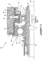
- Fig. 5 shows a schematic axial sectional view showing the low pressure engine shaft 17 mounted to the stationary engine casing 22 via a bearing assembly 18.
- the bearing assembly 18 includes the forward bearing 20 mounted in tandem configuration with an auxiliary bearing 30.
- the auxiliary bearing 30 has an outer race 31 and an inner race 32, and rolling elements 33, shown as balls in the depicted embodiment.
- the parts of the auxiliary bearing 30 may be made of any suitable material, such as stainless steel, ceramic, or a combination thereof, for instance.
- the auxiliary bearing 30 may or may not be dimensioned or made of the same material as the forward bearing 20, depending on the embodiments. While in the depicted embodiment, the forward bearing 20, which may also be referred to as the main bearing of the engine 2,3 in some embodiments, is located axially closer to the gearbox 4 than the auxiliary bearing 30, their relative position may be interchanged in other embodiments.
- the forward bearing 20 and the auxiliary bearing 30 are clamped together.
- the inner races 23, 32 of the bearings 20, 30 are axially secured between an axial fastener 40 and a shoulder 41 of the low-pressure engine shaft 17.
- shoulder 41 is an integral part of the low-pressure engine shaft 17, but it may be formed of a separate part connected (fastened or otherwise secured) to the low-pressure engine shaft 17 in alternate embodiments.
- the axial fastener 40 may be a nut screwed on the low-pressure engine shaft 17, for instance. Other axial fastener 40 may be contemplated.
- auxiliary bearing 30 inner race 32 abuts against the shoulder 41 of the low-pressure engine shaft 17, and the forward bearing 20 inner race 23 is located between the inner race 32 of the auxiliary bearing 30 and the axial fastener 40.
- Such bearing arrangement may be referred to as a tandem arrangement in some embodiments.
- the forward bearing 20 and the auxiliary bearing 30 remain at a fixed distance with respect to each other.
- the forward bearing 20 and the auxiliary bearing 30 are coupled together such that their relative axial position is fixed (fixed or substantially fixed) whether or not the gas turbine engine 2,3 is run in the standby mode.
- the outer race 21 of the forward bearing 20 defines a radially extending flange 25 interfacing with the engine casing 22 such as to prevent (or block) axial movement of the forward bearing 20 outer race 21 relative to the engine casing 22 in a rearward direction (the rearward direction being defined as rearward, along the low-pressure engine shaft 17, in that it points away from the gearbox 4 or stated differently towards the turbine section 13).
- forward bearing 20 and the auxiliary bearing 30 are shown in direct contact with one another via a portion of their respective inner races 23, 32, the forward bearing 20 and the auxiliary bearing 30 may be otherwise connected or secured to one another via an intermediate part in other embodiments.
- the auxiliary bearing 30 is configured to generate an axial preload force on the forward bearing 20.
- the auxiliary bearing 30 includes a hydraulic device 34, which is integrated with, or stated differently integral to, the auxiliary bearing 30. More particularly, in the depicted embodiment, the hydraulic device 34 is integrated in the outer race 31 of the auxiliary bearing 30.
- the hydraulic device 34 is integrated or "integral" with the auxiliary bearing 30 in that the bearing 30 itself has portions of its body defining components or parts of the hydraulic device 34, as opposed to be a standalone hydraulic device 34 made of separate components added and adapted to the bearing assembly 18 or engine casing 22. Integrating the features of the hydraulic device 34 in components of the auxiliary bearing 30 allows for minimizing the space required for such device and its associated weight, for instance. Limiting the number of movable parts may also be desirable to limit the required maintenance of the hydraulic device 34 over time.
- the hydraulic device 34 includes an oil piston 34A.
- the outer race 32 of the auxiliary bearing 30 defines a flange 35.
- Such flange 35 extends radially outwardly.
- the flange 35 extends radially away from the rolling elements 33 (or radially away from the inner race 31).
- the flange 35 may be an axially forward flange or an axially rearward flange of the bearing when viewed along the longitudinal axis of the engine. In Fig.
- the flange 35 is an axially rearward flange 35, in that it is located aft of the rolling elements 33 relative to the forward bearing 20 when viewed along the rotation axis R-R of the low-pressure engine shaft 17.
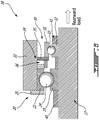
- Fig. 6 shows an alternate embodiment of the bearing assembly 18, where, in this case the flange 35 is a axially forward flange 35, which is located axially forward of the auxiliary bearing 30, between the forward bearing 20 and the rolling elements 33 of the auxiliary bearing 30.
- the flange 35 defines at least part of the oil piston 34A of the auxiliary bearing 30.
- the oil piston 34A defines a surface area on which oil pressure is applied. Such surface area is one factor affecting the capacity of the hydraulic device 34 to exert an axial load and may affect the magnitude of that load.
- an oil chamber 36 (or piston cavity) is circumscribed at least partially by the flange 35. In the depicted embodiment, the oil chamber 36 is defined axially between the flange 35 and a wall of the engine casing 22.
- the oil piston 34A including the flange 35, oil chamber 36 and/or other components of the hydraulic device 34 may extend circumferentially about at least part of the low-pressure engine shaft 17.
- the flange 35 and the oil chamber 36 extends continuously over the full circumference (360°) of the bearing 30. This may ensure that the axial load generated by the hydraulic device 34 on the bearing assembly 18 is applied uniformly around the low-pressure engine shaft 17.
- the oil chamber 36 and/or flange 35 may not extend continuously over the full circumference of the bearing 30 depending on the embodiments.
- there may be more than one oil chamber 36 i.e. a plurality of discrete oil chambers distributed at selected location about the bearing 30 with a corresponding number of flange segments to define a multiple oil pistons 34A system.
- Such oil chamber 36 is sealed.
- the flange 35 is in sealing engagement with the engine casing 22, such that oil chamber 36 can contain oil and sustain oil pressure required to operate the hydraulic device 34.
- An oil supply 37 of the engine 2,3 may feed oil to the oil chamber 36 via an oil channel 38. While the oil supply 37 and oil channel 38 are illustrated proximate to each other in Fig. 5 , the oil supply 37 may be located at another location (location or in another portion) within the engine 2,3. Oil may be supplied by an hydraulic system not only fluidly connected to the hydraulic device 34, but also other systems or components of the engine 2,3 that may require lubrication or oil flow. Stated differently, the hydraulic device 34 may not have a dedicated oil supply 37 or oil system.
- oil may be channeled through at least part of the engine 2, 3 before reaching the oil supply 37 and/or the oil chamber 36.
- the oil supply 37 may be part of the engine lubrication system.
- the outer race 31 of the auxiliary bearing 30 is configured to move axially relative to the engine casing 22.
- the outer race 31 is not fixed relative to the engine casing 22.
- the outer race 31 may also move relative to the inner race 32, which is axially fixed and coupled to the low-pressure engine shaft 17.
- pressurized oil may be supplied into the oil chamber 36 to apply an axial load on the flange 35.
- the rolling elements 33 may thus oppose to the axial movement of the outer race 31.
- the outer race 31 axially loading the rolling elements 33 may in turn transmit the axial load to the inner race 32 of the bearing 30 (reaction force of the fixed inner race 32 opposing the axial load generated at the outer race 31).
- Such axial load generated by the hydraulic device 34 is transmitted to the forward bearing 20 as a consequence of the tandem configuration of the forward and auxiliary bearings 20, 30.
- a fixed distance between the forward and auxiliary bearings 20, 30 is maintained while the axial preload force is generated on the bearings 20, 30.
- the low-pressure engine shaft 17 may thus be biased rearwardly (i.e. in the rearward direction, towards the turbine section 13 or away from the gearbox 4).
- Fig. 6 One difference in Fig. 6 is the location of the oil chamber 36 relative to auxiliary bearing 30.
- the oil chamber 36 of the hydraulic device is defined between the flange 35 and the engine casing 22 similarly as discussed above.
- the oil chamber 36 is located axially between the forward bearing 20 and the auxiliary bearing 30.
- the flange 35 is in sealing engagement with the engine casing 22, just as in Fig. 5 .
- the oil chamber 36 is thus circumscribed by a wall of the engine casing 22 and the flange 35 in sealing engagement therewith.
- the bearings 20, 30 illustrated in a tandem configuration are axially maintained at a fixed distance from each other, between the axial fastener 40 and the shoulder 41 of the low-pressure engine shaft 17.
- the so-generated axial load by the hydraulic device 34 and bearings 20, 30 in the tandem configuration as discussed above may compensate for the lack of aerodynamic load (lack of sufficient aerodynamic load, or absence of aerodynamic load) as a consequence of the standby mode operating condition of the engine 2,3 so affected.
- Such biasing force may oppose to vibrations and/or limit axial load fluctuations (also known as "chucking loads") transmitted to the bearings 20, 30.
- the hydraulic device 34 may be sized to allow generating sufficient axial pre-load force for compensating the lack of aerodynamic load typically present when at the engine 2, 3 is operated in standby mode.
- oil may be supplied at a constant pressure on the outer race 31 (the flange 35) to apply a constant pre-load force, irrespective of the actual level of aerodynamic load.
- a valve or other pressure regulator may be used to limit or control the oil pressure.
- the pre-axial load force may be adjusted to a selected force level depending on the amplitude of aerodynamic load to compensate for.
- Such controllable valve may be controlled via one or more controller(s) (such as the exemplary controllers described above).
- the hydraulic device 34 described herein may advantageously provide an axial pre-load force on the low-pressure engine shaft 17 via the auxiliary bearing 30 when the gas turbine engine 2,3 run in the standby mode, such axial pre-load force may be continuously applied on the low-pressure engine shaft 17, whether or not the engine 2,3 is operating in the standby mode.
- the axial pre-load force generated by the hydraulic device 34 may be applied while the engine 2,3 is operated in the full-power mode or "active". This may allow simpler hydraulic systems, as no valve(s) or electronic actuator(s) may be required to control and/or vary the oil feed and/or oil pressure channeled to the hydraulic device 34. This may consequently simplify the hydraulic system and reduce weight of the engines 2, 3 comprising such hydraulic device 34.
- the hydraulic device 34 described herein may stabilize the load applied on the rolling elements of the bearings and maintain the position of the rolling elements, which may contribute in maximizing service life of the forward bearing 20 and/or auxiliary bearing 30. Because of the reduced amount of moving parts in the hydraulic device 34, such device 34 may be easier to install and last longer than other types of devices that would use springs, for instance.
Landscapes
- Engineering & Computer Science (AREA)
- General Engineering & Computer Science (AREA)
- Mechanical Engineering (AREA)
- Support Of The Bearing (AREA)
Abstract
Description
- The disclosure relates generally to multi-engine aircraft and methods of operating same, and more particularly to operation of an aircraft propulsion gas turbine engine in a multi-engine aircraft.
- In multi-engine aircraft, such as helicopters, two or more propulsion gas turbine engines may be provided to drive a main rotor via a common gearbox, and each of the engines is sized to provide power greater than what is required for cruising using both/all engines. It can however be desirable to operate one of the engines at a very low power output (e.g. "standby" condition) during cruise, in order to reduce fuel consumption of this engine.
- However, because most gas turbine engines are designed to run optimally at power outputs greater than the very low power conditions of such a standby mode, a number of considerations must be taken into account in order to be able to effectively operate one of the engines in a low power mode.
- There is accordingly provided a method of operating a gas turbine engine of a multi-engine aircraft, the gas turbine engine having an engine shaft mounted for rotation in a bearing of a bearing assembly, the method comprising: limiting motive power supplied to the aircraft by the gas turbine engine by operating the gas turbine engine in a standby mode; and when the gas turbine engine is operating in the standby mode, using an oil piston integrated in the bearing supporting the engine shaft of the gas turbine engine to generate an axial preload force on the bearing.
- The method as described above and herein may further include, in whole or in part, and in any combination, one or more of the following steps and/or features.
- In an embodiment of the above, the method comprises operating another gas turbine engine of the multi-engine aircraft in an active mode to supply a larger amount of motive power to the aircraft than the gas turbine engine operated in the standby mode.
- In a further embodiment of any of the above, the gas turbine engines drive a common load, wherein operating one of the gas turbine engine in the standby mode supplies none of a required motive power to the common load, while the gas turbine engine in the active mode supplies all of the required motive power to the common load.
- In a further embodiment of any of the above, the method comprises using the oil piston includes supplying pressurized oil into a piston cavity of the bearing assembly from an oil supply of the gas turbine engine.
- In a further embodiment of any of the above, the oil piston is integrated in an outer race of the bearing, wherein using the oil piston includes applying the axial preload force on a flange of the outer race of the bearing.
- In a further embodiment of any of the above, the method comprises using the oil piston includes biasing axially an inner race of the bearing against a shoulder defined on the engine shaft to load the engine shaft in a direction of the axial preload force.
- In a further embodiment of any of the above, the method comprises using the oil piston includes supplying pressurized oil at a constant pressure on the outer race of the bearing to generate the axial preload force.
- In a further embodiment of any of the above, the bearing of the bearing assembly is a first bearing, the bearing assembly including a second bearing, the first and second bearings mounted in a tandem configuration, the method comprising maintaining a fixed distance between the first and the second bearing in the tandem configuration while applying the axial preload force.
- In a further embodiment of any of the above, the method comprises using the oil piston includes applying the axial preload force on the first bearing and the second bearing in a rearward load direction along the engine shaft.
- In a further embodiment of any of the above, the first and second bearings each have an inner race axially secured to the engine shaft, wherein applying the axial preload force on the first and second bearings in the rearward load direction includes biasing the engine shaft in the rearward load direction to compensate for a lack of aerodynamic load on the engine shaft.
- There is further provided a method of providing a preload force on a bearing of a bearing assembly, the bearing supporting a shaft in a gas turbine engine, the method comprising: using an oil piston integrated into a flange of the bearing to apply an axial force on an outer race of the bearing, the axial force being applied continuously on the bearing during operation of the gas turbine engine.
- The method as described above and herein may further include, in whole or in part, and in any combination, one or more of the following steps and/or features.
- In a further embodiment of any of the above, the method comprises using the oil piston includes supplying pressurized oil at a constant pressure on the flange of the bearing.
- In a further embodiment of any of the above, the flange at least partially circumscribes a piston cavity, the method comprising adjusting an oil pressure exerted on the flange to a desired pressure via an oil valve fluidly connected upstream of the piston cavity.
- In a further embodiment of any of the above, the bearing is a first bearing, the bearing assembly includes a second bearing mounted in a tandem configuration with the first bearing, wherein using the oil piston includes biasing the first and the second bearings in a rearward load direction along a rotation axis of the gas turbine engine.
- In a further embodiment of any of the above, the method comprises applying the axial force on the outer race includes biasing axially an inner race of the bearing via rolling elements of the bearing interfacing between the outer race and the inner race against a complementary shoulder of the engine shaft to load the engine shaft in a rearward load direction along a rotation axis of the gas turbine engine.
- There is further provided a bearing assembly for supporting an engine shaft, comprising: a bearing having an inner race, an outer race and a series of rolling elements disposed between the inner race and the outer race, the inner race of the bearing coupled to the engine shaft, the outer race of the bearing defining a flange; and an oil piston integrated into the bearing flange, the oil piston including a piston cavity, the bearing flange at least partially circumscribing the piston cavity, the oil piston configured to apply an axial preload force against the rolling elements of the bearing and in turn to the engine shaft coupled to the bearing inner race.
- The bearing assembly as described above and herein may further include, in whole or in part, and in any combination, one or more of the following features.
- In an embodiment of the above, the bearing has rolling elements interfacing between the outer race and an inner race, the flange being axially offset from the rolling elements, the flange extending radially outward from the rolling elements.
- In a further embodiment of any of the above, the bearing is a first bearing, the bearing assembly comprising a second bearing, the second bearing mounted to the engine shaft, the first bearing and the second bearing each having an inner race, the inner races of the first and second bearings axially secured to the engine shaft and contacting each other.
- In a further embodiment of any of the above, the first bearing and the second bearing each have an inner race, the engine shaft defining a shoulder, the inner race of the first bearing abutting against the shoulder and the inner race of the second bearing abutting against the inner race of the first bearing.
- In a further embodiment of any of the above, the inner races of the first and second bearing are clamped on each other between the shoulder and an axial fastener engaging the engine shaft.
- Further details of these and other aspects of the subject matter of this application will be apparent from the detailed description included below and the drawings.
-
-
Fig. 1 is a schematic view of an example multi-engine aircraft comprising a dual engine helicopter. -
Fig. 2 is a schematic axial sectional view through the dual engines of the aircraft inFig. 1 with the engine connector shafts joined to the helicopter gearbox. -
Fig. 3 is a partial axial cross-sectional view through an engine showing a forward bearing supporting an engine shaft. -
Fig. 4 is a detail axial sectional view, taken fromregion 4 inFig. 3 , showing the forward bearing of engine. -
Fig. 5 is a schematic axial sectional view showing the engine shaft mounted for rotation in a bearing assembly. -
Fig. 6 is another schematic axial sectional view likeFig. 5 with an alternate configuration of the bearing assembly. -
Fig. 1 depicts an exemplary multi-engine aircraft 1, such as a helicopter. The aircraft 1 may however also be a multi-engine fixed-wing aircraft. The aircraft 1 includes at least twogas turbine engines common gearbox 4 to form amulti-engine drive system 5 as shown inFig. 2 . -
Fig. 2 illustrates a schematic representation of an exemplarymulti-engine system 5 that may be used as a power plant for the aircraft 1. Themulti-engine system 5 comprises two or moregas turbine engines multi-engine system 5 may be used in marine or industrial applications. Themulti-engine system 5 ofFig. 2 includes main and reserve turboshaftgas turbine engines engine shaft 6, 7 that are interconnected by aconnector shaft 8, 9 of thecommon gearbox 4 to drive acommon load shaft 10. In one embodiment, thecommon load shaft 10 may drive arotary wing 20 of a rotary-wing aircraft. - Each of
turboshaft engines common load shaft 10 via thegearbox 4, which may be of a speed-reduction type. Thegear box 4 may be configured to permit thecommon load shaft 10 to be driven by either of theturboshaft engines engines engine 2 is operated to deliver motive power while theother engine 3 is in idle mode. For example an idle cruise regime may be used in multi-engine aircraft 1 to reduce fuel consumption during cruise operation while bothengines engine 2 is sufficient for the demand and theother engine 3 may be operated in idle mode to reduce fuel consumption and serve as a standby. - Referring to
Fig. 3 , thegas turbine engines compressor section 11 for pressurizing the air, acombustor 12 in where the compressed air is mixed with fuel and ignited for generating an annular stream of hot combustion gases, and aturbine section 13 for extracting energy from the combustion gases. In the embodiment ofFig. 3 , ahigh pressure turbine 14 drives a highpressure engine shaft 15 to which thecompressor section 11 is connected for driving the highpressure engine shaft 15. Alow pressure turbine 16 drives a lowpressure turbine shaft 17 which is coaxial with the highpressure engine shaft 15. - Referring to
Figs. 3 and4 , the lowpressure turbine shaft 17 is supported by the forward bearing 18. A slidingspline joint 19 connects the engine output shaft 7 and the lowpressure turbine shaft 17. As indicated inFig. 2 , theengine output shafts 6, 7 drive theconnector shafts 8, 9, thegearbox 4, and thecommon load shaft 10. - The present description relates generally to operating a multi-engine system 1, where one
engine 2 is capable of providing motive power, and asecond engine 3 may be maintained in a very low-power, or idle mode to reduce fuel consumption while remaining on standby or reserve if needed for additional motive power. - With reference to the
gas turbine engines Fig. 2 , control of themulti-engine system 5 comprising these twoengines - While the helicopter conditions (cruise speed and altitude) are substantially stable, the
engines multi-engine system 5 may be operated asymmetrically, with one engine operated in a high-power "active" mode and the other engine operated in a low-power "standby" mode. Doing so may provide fuel saving opportunities to the helicopter, however there may be other suitable reasons why the engines are desired to be operated asymmetrically. This operation management may therefore be referred to as an "asymmetric mode" or an "asymmetric operating regime", wherein one of the two engines is operated in a low-power "standby mode" while the other engine is operated in a high-power "active" mode. In such an asymmetric mode, which may be engaged during a helicopter cruise phase of flight (continuous, steady-state flight which is typically at a given commanded constant helicopter cruising speed and altitude). The multi-engine system may be used in an aircraft, such as a helicopter, but also has applications in suitable marine and/or industrial applications or other ground operations. - According to the present description, the
multi-engine system 5 driving the helicopter 1 may be operated in this asymmetric mode, in which a first of the turboshaft engines (say, the first engine 2) may be operated at high power in an active mode and a second engine (say, the second engine 3) may be operated in a low-power standby mode. In one example, thefirst turboshaft engine 2 may be controlled by the controller(s) to run at full (or near-full) power conditions in the active mode, to supply substantially all or all of a required power and/or speed demand of the common load. Thesecond turboshaft engine 3 may be controlled by the controller(s) to run at low-power or no-output-power conditions to supply substantially none or none of a required power and/or speed demand of the common load. Optionally, a clutch may be provided to declutch the low-power engine. Controller(s) may control the engine's governing on power according to an appropriate schedule or control regime. The controller(s) may comprise a first controller for controlling the first engine and a second controller for controlling the second engine. The first controller and the second controller may be in communication with each other in order to implement the operations described herein. In some embodiments, a single controller may be used for controlling the first engine and the second engine. - In another example, an asymmetric operating regime of the engines may be achieved through the one or more controller's differential control of fuel flow to the engines, as described in
pending US application 16/535,256 - When one of the two engines, such as the
second engine 3, is run in the standby mode as described above, a significantly lower axial load is generated on the forward bearing 20 of the standby engine relative to the "active" engine providing full power. This lower axial load may be limited to the aerodynamic load imposed by the low pressure turbines and/or compressors operating under such standby conditions. Consequently, the forward bearing can be left practically free of axial loading from the engine and subjected to alternating axial loads generated by helicopter main rotor load in load fluctuations from the helicopter gear box and helicopter rotor blades. This is undesirable for bearing structural integrity, as many bearings, and particularly ball bearings, require a certain amount of axial loading to be maintained in order to ensure maximize service life. - Referring now to
Fig. 4 , the present description will now refer in particular to theforward bearing 20 and the means by which a minimal axial load or preload is applied to avoid load reversals and reduce wear will be described with reference to features of an exemplary axial pre-load device depicted atFig. 5 . As noted above, the idle cruise regime condition generates a significantly low axial load on theforward bearing 20, generally limited to the aerodynamic load delivered by thelow pressure turbines 16 operating under idle conditions. In the example ofFig. 4 , the forward bearing 20 is substantially free (substantially free or almost free) of axial loading (arrow X) from the lowpressure engine shaft 17 and is subjected to possibly alternating directional axial load (arrow Y) transmitted by the engine output shaft 7 originating from the helicopter main rotor load fluctuations transmitted by thehelicopter gearbox 4 and helicopter rotor blades (20-seeFig. 1 ). The helicopter main rotor load fluctuations are due to vibrations and relative motion between thehelicopter gearbox 4 and theconnector shafts 8, 9. The relative motion tends to alternatively load theforward bearing 20. Theouter race 21 of theforward bearing 20 is attached to thestationary engine casing 22 while theinner race 23 is mounted to the engine rotor (including the lowpressure engine shaft 17 and engine output shaft 7). The alternating bearing loading condition is not desirable for structural integrity of theforward bearing 20 and a reduced bearing service life may result. Preferably the axial load on theball 24,outer race 21 andinner race 23 does not alternate in axial direction but remains preloaded or uni-directional at an axial load value above a minimum axial load value. Although the Figures illustrate aball 24 as a bearing member, it will be understood that other suitable rolling members capable of transmitting axial loads may also be used, such as conical rollers. -
Fig. 5 shows a schematic axial sectional view showing the lowpressure engine shaft 17 mounted to thestationary engine casing 22 via a bearingassembly 18. As depicted, the bearingassembly 18 includes theforward bearing 20 mounted in tandem configuration with anauxiliary bearing 30. - The
auxiliary bearing 30 has anouter race 31 and aninner race 32, and rollingelements 33, shown as balls in the depicted embodiment. The parts of theauxiliary bearing 30 may be made of any suitable material, such as stainless steel, ceramic, or a combination thereof, for instance. - The
auxiliary bearing 30 may or may not be dimensioned or made of the same material as theforward bearing 20, depending on the embodiments. While in the depicted embodiment, the forward bearing 20, which may also be referred to as the main bearing of theengine gearbox 4 than theauxiliary bearing 30, their relative position may be interchanged in other embodiments. - In the depicted embodiment the
forward bearing 20 and theauxiliary bearing 30 are clamped together. As shown, theinner races bearings axial fastener 40 and ashoulder 41 of the low-pressure engine shaft 17. In the embodiment shown,such shoulder 41 is an integral part of the low-pressure engine shaft 17, but it may be formed of a separate part connected (fastened or otherwise secured) to the low-pressure engine shaft 17 in alternate embodiments. Theaxial fastener 40 may be a nut screwed on the low-pressure engine shaft 17, for instance. Otheraxial fastener 40 may be contemplated. As shown, theauxiliary bearing 30inner race 32 abuts against theshoulder 41 of the low-pressure engine shaft 17, and the forward bearing 20inner race 23 is located between theinner race 32 of theauxiliary bearing 30 and theaxial fastener 40. Such bearing arrangement may be referred to as a tandem arrangement in some embodiments. - The
forward bearing 20 and theauxiliary bearing 30 remain at a fixed distance with respect to each other. In other words, the forward bearing 20 and theauxiliary bearing 30 are coupled together such that their relative axial position is fixed (fixed or substantially fixed) whether or not thegas turbine engine - In the depicted embodiment, the
outer race 21 of theforward bearing 20 defines aradially extending flange 25 interfacing with theengine casing 22 such as to prevent (or block) axial movement of theforward bearing 20outer race 21 relative to theengine casing 22 in a rearward direction (the rearward direction being defined as rearward, along the low-pressure engine shaft 17, in that it points away from thegearbox 4 or stated differently towards the turbine section 13). - While the
forward bearing 20 and theauxiliary bearing 30 are shown in direct contact with one another via a portion of their respectiveinner races auxiliary bearing 30 may be otherwise connected or secured to one another via an intermediate part in other embodiments. - The
auxiliary bearing 30 is configured to generate an axial preload force on theforward bearing 20. Theauxiliary bearing 30 includes ahydraulic device 34, which is integrated with, or stated differently integral to, theauxiliary bearing 30. More particularly, in the depicted embodiment, thehydraulic device 34 is integrated in theouter race 31 of theauxiliary bearing 30. Thehydraulic device 34 is integrated or "integral" with theauxiliary bearing 30 in that the bearing 30 itself has portions of its body defining components or parts of thehydraulic device 34, as opposed to be a standalonehydraulic device 34 made of separate components added and adapted to the bearingassembly 18 orengine casing 22. Integrating the features of thehydraulic device 34 in components of theauxiliary bearing 30 allows for minimizing the space required for such device and its associated weight, for instance. Limiting the number of movable parts may also be desirable to limit the required maintenance of thehydraulic device 34 over time. - In the depicted embodiment, the
hydraulic device 34 includes an oil piston 34A. Theouter race 32 of theauxiliary bearing 30 defines aflange 35.Such flange 35 extends radially outwardly. In other words, theflange 35 extends radially away from the rolling elements 33 (or radially away from the inner race 31). Depending on the embodiment, theflange 35 may be an axially forward flange or an axially rearward flange of the bearing when viewed along the longitudinal axis of the engine. InFig. 5 , theflange 35 is an axiallyrearward flange 35, in that it is located aft of the rollingelements 33 relative to theforward bearing 20 when viewed along the rotation axis R-R of the low-pressure engine shaft 17.Fig. 6 shows an alternate embodiment of the bearingassembly 18, where, in this case theflange 35 is a axiallyforward flange 35, which is located axially forward of theauxiliary bearing 30, between theforward bearing 20 and the rollingelements 33 of theauxiliary bearing 30. - Returning to
Fig. 5 , theflange 35 defines at least part of the oil piston 34A of theauxiliary bearing 30. The oil piston 34A defines a surface area on which oil pressure is applied. Such surface area is one factor affecting the capacity of thehydraulic device 34 to exert an axial load and may affect the magnitude of that load. As shown, an oil chamber 36 (or piston cavity) is circumscribed at least partially by theflange 35. In the depicted embodiment, theoil chamber 36 is defined axially between theflange 35 and a wall of theengine casing 22. While the Figures show these components in an axial cross-section, it should be understood that the oil piston 34A, including theflange 35,oil chamber 36 and/or other components of thehydraulic device 34 may extend circumferentially about at least part of the low-pressure engine shaft 17. For instance, in an embodiment, theflange 35 and theoil chamber 36 extends continuously over the full circumference (360°) of thebearing 30. This may ensure that the axial load generated by thehydraulic device 34 on the bearingassembly 18 is applied uniformly around the low-pressure engine shaft 17. Even if less desirable, theoil chamber 36 and/orflange 35 may not extend continuously over the full circumference of thebearing 30 depending on the embodiments. For instance, there may be more than oneoil chamber 36, i.e. a plurality of discrete oil chambers distributed at selected location about the bearing 30 with a corresponding number of flange segments to define a multiple oil pistons 34A system. -
Such oil chamber 36 is sealed. Theflange 35 is in sealing engagement with theengine casing 22, such thatoil chamber 36 can contain oil and sustain oil pressure required to operate thehydraulic device 34. Anoil supply 37 of theengine oil chamber 36 via anoil channel 38. While theoil supply 37 andoil channel 38 are illustrated proximate to each other inFig. 5 , theoil supply 37 may be located at another location (location or in another portion) within theengine hydraulic device 34, but also other systems or components of theengine hydraulic device 34 may not have a dedicatedoil supply 37 or oil system. As such, oil may be channeled through at least part of theengine oil supply 37 and/or theoil chamber 36. For instance, theoil supply 37 may be part of the engine lubrication system. However, in other cases, there may be a separate hydraulic system with a dedicated pump (not shown) to feed thehydraulic device 34. - In the depicted embodiment, the
outer race 31 of theauxiliary bearing 30 is configured to move axially relative to theengine casing 22. Theouter race 31 is not fixed relative to theengine casing 22. Theouter race 31 may also move relative to theinner race 32, which is axially fixed and coupled to the low-pressure engine shaft 17. During operation of thehydraulic device 34, pressurized oil may be supplied into theoil chamber 36 to apply an axial load on theflange 35. The rollingelements 33 may thus oppose to the axial movement of theouter race 31. Theouter race 31 axially loading the rollingelements 33 may in turn transmit the axial load to theinner race 32 of the bearing 30 (reaction force of the fixedinner race 32 opposing the axial load generated at the outer race 31). Such axial load generated by thehydraulic device 34 is transmitted to the forward bearing 20 as a consequence of the tandem configuration of the forward andauxiliary bearings auxiliary bearings bearings pressure engine shaft 17 may thus be biased rearwardly (i.e. in the rearward direction, towards theturbine section 13 or away from the gearbox 4). - The above also applies to the alternate embodiment shown in
Fig. 6 . One difference inFig. 6 is the location of theoil chamber 36 relative toauxiliary bearing 30. As shown, in the depicted embodiment ofFig. 6 , theoil chamber 36 of the hydraulic device is defined between theflange 35 and theengine casing 22 similarly as discussed above. However, inFig. 6 , theoil chamber 36 is located axially between theforward bearing 20 and theauxiliary bearing 30. Theflange 35 is in sealing engagement with theengine casing 22, just as inFig. 5 . Theoil chamber 36 is thus circumscribed by a wall of theengine casing 22 and theflange 35 in sealing engagement therewith. Thebearings axial fastener 40 and theshoulder 41 of the low-pressure engine shaft 17. - The so-generated axial load by the
hydraulic device 34 andbearings engine bearings hydraulic device 34 may be sized to allow generating sufficient axial pre-load force for compensating the lack of aerodynamic load typically present when at theengine engines - While the
hydraulic device 34 described herein may advantageously provide an axial pre-load force on the low-pressure engine shaft 17 via theauxiliary bearing 30 when thegas turbine engine pressure engine shaft 17, whether or not theengine hydraulic device 34 may be applied while theengine hydraulic device 34. This may consequently simplify the hydraulic system and reduce weight of theengines hydraulic device 34. - The
hydraulic device 34 described herein may stabilize the load applied on the rolling elements of the bearings and maintain the position of the rolling elements, which may contribute in maximizing service life of theforward bearing 20 and/orauxiliary bearing 30. Because of the reduced amount of moving parts in thehydraulic device 34,such device 34 may be easier to install and last longer than other types of devices that would use springs, for instance. - The above description is meant to be exemplary only, and one skilled in the relevant arts will recognize that changes may be made to the embodiments described without departing from the scope of the invention disclosed. The present disclosure may be embodied in other specific forms without departing from the subject matter of the claims. The present disclosure is intended to cover and embrace all suitable changes in technology. Modifications which fall within the scope of the present invention will be apparent to those skilled in the art, in light of a review of this disclosure, and such modifications are intended to fall within the appended claims. Also, the scope of the claims should not be limited by the embodiments set forth in the examples, but should be given the broadest interpretation consistent with the description as a whole.
Claims (15)
- A method of operating a gas turbine engine (3) of a multi-engine aircraft (1), the gas turbine engine (3) having an engine shaft (17) mounted for rotation in a bearing (20, 30) of a bearing assembly (18), the method comprising:limiting motive power supplied to the aircraft (1) by the gas turbine engine (3) by operating the gas turbine engine (3) in a standby mode; andat least when the gas turbine engine (3) is operating in the standby mode, using an oil piston integrated in the bearing (20, 30) supporting the engine shaft (17) of the gas turbine engine (3) to generate an axial preload force on the bearing (20, 30).
- The method as defined in claim 1, further comprising operating a second gas turbine engine (2) of the multi-engine aircraft (1) in an active mode to supply a larger amount of motive power to the aircraft (1) than the gas turbine engine (3) operated in the standby mode.
- The method as defined in claim 2, wherein the gas turbine engine (3) and second gas turbine engine (2) drive a common load, wherein the gas turbine engine (3) operating in the standby mode supplies none of a required motive power to the common load, and the second gas turbine engine (2) operating in the active mode supplies all of the required motive power to the common load.
- The method as defined in any of the preceding claims, wherein using the oil piston includes supplying pressurized oil into a piston cavity of the bearing assembly (18) from an oil supply (37) of the gas turbine engine (3).
- The method as defined in claim 4, further comprising adjusting an oil pressure to a desired pressure via an oil valve fluidly connected upstream of the piston cavity.
- The method as defined in any of the preceding claims, wherein the oil piston is integrated in an outer race (21, 31) of the bearing (20, 30), and the step of using the oil piston includes applying the axial preload force on a flange (35) of the outer race (21, 31) of the bearing (21, 31).
- The method as defined in any of the preceding claims, wherein the step of using the oil piston includes biasing axially an inner race (23, 32) of the bearing (20, 30) against a complementary shoulder (41) defined on the engine shaft (17) to load the engine shaft (17) in a direction of the axial preload force, the direction optionally being a rearward load direction along a rotation axis of the gas turbine engine (3).
- The method as defined in any of the preceding claims, wherein using the oil piston includes supplying pressurised oil at a constant pressure on an or the outer race (21, 31) of the bearing (20, 30) to generate the axial preload force.
- The method as defined in any of the preceding claims, wherein the bearing (20, 30) of the bearing assembly (18) is a first bearing (20, 30), the bearing assembly (18) includes a second bearing (20, 30), the first and second bearings (20, 30) are mounted in a tandem configuration, and the method comprises maintaining a fixed distance between the first and second bearings (20, 30) in the tandem configuration while applying the axial preload force, and optionally using the oil piston includes applying the axial preload force on the first bearing and the second bearing (20, 30) in a rearward load direction along the engine shaft (17).
- The method as defined in claim 9, wherein the first and second bearings (20, 30) each have an or the inner race (23, 32) axially secured to the engine shaft (17), and applying the axial preload force on the first and second bearings (20, 30) in the rearward load direction includes biasing the engine shaft (17) in the rearward load direction to compensate for a lack of aerodynamic load on the engine shaft (17).
- The method as defined in any of the preceding claims, further comprising continuously applying the axial preload force on the bearing (20, 30) during operation of the gas turbine engine (3).
- A bearing assembly (18) for supporting an engine shaft (17), comprising:a bearing (20, 30) having an inner race (23, 32), an outer race (21, 31) and a series of rolling elements (33) disposed between the inner race (23, 32) and the outer race (21, 31), wherein the inner race (23, 32) of the bearing (20, 30) is coupled to the engine shaft (17), and the outer race (21, 31) of the bearing (20, 30) defines a flange (35); andan oil piston integrated into the bearing flange (35), the oil piston including a piston cavity, the bearing flange (35) at least partially circumscribing the piston cavity, and the oil piston configured to apply an axial preload force against the rolling elements (33) of the bearing (20, 30) and in turn to the engine shaft (17) coupled to the bearing inner race (23, 32).
- The bearing assembly as defined in claim 12, wherein the rolling elements (33) interface between the outer race (21, 31) and the inner race (23, 32), the flange (35) being axially offset from the rolling elements (33) and the flange (35) extending radially outward from the rolling elements (33).
- The bearing assembly as defined in claim 12 or 13, wherein the bearing (20, 30) is a first bearing (20, 30), the bearing assembly (18) comprises a second bearing (20, 30), the second bearing (20, 30) is mounted to the engine shaft (17), the first bearing (20, 30) and the second bearing (20, 30) each have an inner race (23, 32), and the inner races (23, 32) of the first and second bearings (20, 30) are axially secured to the engine shaft (17) and contact each other.
- The bearing assembly as defined in claim 14, wherein the first bearing (20, 30) and the second bearing (20, 30) each have an inner race (23, 32), the engine shaft (17) defines a shoulder (41), the inner race (23, 32) of the first bearing (20, 30) abuts against the shoulder (41), and the inner race (23, 32) of the second bearing (20, 30) abuts against the inner race (23, 32) of the first bearing (20, 30), and optionally the inner races (23, 32) of the first and second bearings (20, 30) are clamped to each other between the shoulder (17) and an axial fastener (40) engaging the engine shaft (17).
Applications Claiming Priority (1)
| Application Number | Priority Date | Filing Date | Title |
|---|---|---|---|
| US16/671,485 US11021994B2 (en) | 2019-11-01 | 2019-11-01 | Flanged integral piston bearing |
Publications (2)
| Publication Number | Publication Date |
|---|---|
| EP3816411A1 true EP3816411A1 (en) | 2021-05-05 |
| EP3816411B1 EP3816411B1 (en) | 2024-05-01 |
Family
ID=73043183
Family Applications (1)
| Application Number | Title | Priority Date | Filing Date |
|---|---|---|---|
| EP20205187.6A Active EP3816411B1 (en) | 2019-11-01 | 2020-11-02 | Flanged integral piston bearing |
Country Status (2)
| Country | Link |
|---|---|
| US (1) | US11021994B2 (en) |
| EP (1) | EP3816411B1 (en) |
Cited By (1)
| Publication number | Priority date | Publication date | Assignee | Title |
|---|---|---|---|---|
| EP4224029A1 (en) * | 2022-02-02 | 2023-08-09 | Pratt & Whitney Canada Corp. | Loaded bearing system |
Families Citing this family (2)
| Publication number | Priority date | Publication date | Assignee | Title |
|---|---|---|---|---|
| US11976593B1 (en) * | 2022-10-24 | 2024-05-07 | General Electric Company | Bearing assembly |
| US12560100B1 (en) * | 2024-10-15 | 2026-02-24 | Pratt & Whitney Canada Corp. | Double directionally pre-loaded damped ball bearing |
Citations (4)
| Publication number | Priority date | Publication date | Assignee | Title |
|---|---|---|---|---|
| US5051005A (en) * | 1990-08-17 | 1991-09-24 | The Torrington Company | Variable preload bearing apparatus |
| EP2050932A2 (en) * | 2007-10-20 | 2009-04-22 | Rolls-Royce plc | A shaft bearing arrangement in a gas turbine engine and a method for operating this bearing arrangement |
| EP2921729A2 (en) * | 2014-03-19 | 2015-09-23 | Rolls-Royce plc | Bearing arrangement |
| US20190195088A1 (en) * | 2017-12-21 | 2019-06-27 | United Technologies Corporation | Flexible preloaded ball bearing assembly |
Family Cites Families (20)
| Publication number | Priority date | Publication date | Assignee | Title |
|---|---|---|---|---|
| US3738719A (en) * | 1970-08-04 | 1973-06-12 | Snecma | Ball bearing |
| JPS61211519A (en) * | 1985-03-13 | 1986-09-19 | Nissan Motor Co Ltd | Bearing structure of turbocharger |
| US4657412A (en) * | 1985-03-25 | 1987-04-14 | The Torrington Company | Variable preload bearing assembly |
| JPH0835521A (en) | 1994-07-25 | 1996-02-06 | Nippon Seiko Kk | Rolling bearing device |
| US6123462A (en) * | 1998-09-28 | 2000-09-26 | General Electric Company | Bearing system having reduced noise and axial preload |
| US6048101A (en) * | 1998-12-09 | 2000-04-11 | Sullair Corporation | Thrust bearing arrangement |
| DE20202260U1 (en) * | 2002-02-14 | 2002-04-25 | Deckel Maho Pfronten GmbH, 87459 Pfronten | High-speed spindle unit for machine tools |
| US7997804B2 (en) * | 2007-02-06 | 2011-08-16 | Jtekt Corporation | Rolling bearing apparatus |
| US8827564B2 (en) * | 2009-07-31 | 2014-09-09 | Jtekt Corporation | Outer ring of tapered roller bearing, tapered roller bearing, and manufacturing method of outer ring of tapered roller bearing |
| US8439637B2 (en) * | 2009-11-20 | 2013-05-14 | United Technologies Corporation | Bellows preload and centering spring for a fan drive gear system |
| WO2011139310A2 (en) * | 2009-12-29 | 2011-11-10 | Rolls-Royce Corporation | Gas turbine engine and high speed rolling element bearing system |
| JP5573420B2 (en) * | 2010-06-29 | 2014-08-20 | トヨタ自動車株式会社 | Tapered roller bearing |
| CN102979625A (en) * | 2012-11-06 | 2013-03-20 | 中国航空工业集团公司沈阳发动机设计研究所 | Structure for aviation gas turbine rotor supporting point ball bearing axial pre-load |
| KR101366140B1 (en) * | 2013-06-10 | 2014-02-25 | 주식회사 에코텍 | Bearing variable preload(adjustable preload) system utilizing deforming of sealing member and small gap of stroke |
| GB201310834D0 (en) * | 2013-06-18 | 2013-07-31 | Rolls Royce Plc | Bearing arrangement |
| DE102015215750A1 (en) * | 2015-08-18 | 2017-02-23 | Continental Automotive Gmbh | Method for mounting a rolling bearing unit on the rotor of a turbocharger |
| US9702404B2 (en) * | 2015-10-28 | 2017-07-11 | United Technologies Corporation | Integral centering spring and bearing support and method of supporting multiple damped bearings |
| US9932986B2 (en) * | 2016-08-05 | 2018-04-03 | United Technologies Corporation | Variable preloaded duplex thrust bearing system for a geared turbofan engine |
| US10800539B2 (en) * | 2016-08-19 | 2020-10-13 | General Electric Company | Propulsion engine for an aircraft |
| CN109281944B (en) | 2018-10-19 | 2021-01-12 | 中国科学院工程热物理研究所 | Axial force preloading structure of deep groove ball bearing in engine rotor fulcrum |
-
2019
- 2019-11-01 US US16/671,485 patent/US11021994B2/en active Active
-
2020
- 2020-11-02 EP EP20205187.6A patent/EP3816411B1/en active Active
Patent Citations (4)
| Publication number | Priority date | Publication date | Assignee | Title |
|---|---|---|---|---|
| US5051005A (en) * | 1990-08-17 | 1991-09-24 | The Torrington Company | Variable preload bearing apparatus |
| EP2050932A2 (en) * | 2007-10-20 | 2009-04-22 | Rolls-Royce plc | A shaft bearing arrangement in a gas turbine engine and a method for operating this bearing arrangement |
| EP2921729A2 (en) * | 2014-03-19 | 2015-09-23 | Rolls-Royce plc | Bearing arrangement |
| US20190195088A1 (en) * | 2017-12-21 | 2019-06-27 | United Technologies Corporation | Flexible preloaded ball bearing assembly |
Cited By (2)
| Publication number | Priority date | Publication date | Assignee | Title |
|---|---|---|---|---|
| EP4224029A1 (en) * | 2022-02-02 | 2023-08-09 | Pratt & Whitney Canada Corp. | Loaded bearing system |
| US12025017B2 (en) | 2022-02-02 | 2024-07-02 | Pratt & Whitney Canada Corp. | Loaded bearing system |
Also Published As
| Publication number | Publication date |
|---|---|
| US20210131306A1 (en) | 2021-05-06 |
| US11021994B2 (en) | 2021-06-01 |
| EP3816411B1 (en) | 2024-05-01 |
Similar Documents
| Publication | Publication Date | Title |
|---|---|---|
| US9752500B2 (en) | Gas turbine engine with transmission and method of adjusting rotational speed | |
| EP3816411B1 (en) | Flanged integral piston bearing | |
| US9033654B2 (en) | Variable geometry vane system for gas turbine engines | |
| US5235812A (en) | Integrated power unit | |
| EP2050925B1 (en) | A shaft bearing arrangement and corresponding method of operating this arrangement | |
| EP4151842A1 (en) | Aircraft power plant | |
| US9845700B2 (en) | Active seal system | |
| EP4224029B1 (en) | Loaded bearing system | |
| EP3792514B1 (en) | Bearing preload using external gearbox reaction | |
| EP3744636A1 (en) | Air system of multi-engine aircraft | |
| US11421603B2 (en) | Turbojet with step-down mechanism | |
| US20200191276A1 (en) | Device with two structural components and gas turbine engine | |
| US5097658A (en) | Integrated power unit control apparatus and method | |
| US5274992A (en) | Integrated power unit combustion apparatus and method | |
| US5060469A (en) | Integrated power unit control apparatus and method | |
| US11149741B2 (en) | Variable pitch fan for a gas turbine engine | |
| US9926070B2 (en) | Turbine engine having a pair of propellers for an aircraft | |
| EP3789596B1 (en) | Method of operating a gas turbine engine at a low power condition | |
| US20240240566A1 (en) | Pitch lock system | |
| US5160069A (en) | Integrated power unit combustion apparatus and method | |
| US8186168B2 (en) | Thrust balance of rotor using fuel |
Legal Events
| Date | Code | Title | Description |
|---|---|---|---|
| PUAI | Public reference made under article 153(3) epc to a published international application that has entered the european phase |
Free format text: ORIGINAL CODE: 0009012 |
|
| STAA | Information on the status of an ep patent application or granted ep patent |
Free format text: STATUS: THE APPLICATION HAS BEEN PUBLISHED |
|
| AK | Designated contracting states |
Kind code of ref document: A1 Designated state(s): AL AT BE BG CH CY CZ DE DK EE ES FI FR GB GR HR HU IE IS IT LI LT LU LV MC MK MT NL NO PL PT RO RS SE SI SK SM TR |
|
| STAA | Information on the status of an ep patent application or granted ep patent |
Free format text: STATUS: REQUEST FOR EXAMINATION WAS MADE |
|
| 17P | Request for examination filed |
Effective date: 20211105 |
|
| RBV | Designated contracting states (corrected) |
Designated state(s): AL AT BE BG CH CY CZ DE DK EE ES FI FR GB GR HR HU IE IS IT LI LT LU LV MC MK MT NL NO PL PT RO RS SE SI SK SM TR |
|
| STAA | Information on the status of an ep patent application or granted ep patent |
Free format text: STATUS: EXAMINATION IS IN PROGRESS |
|
| 17Q | First examination report despatched |
Effective date: 20230316 |
|
| GRAP | Despatch of communication of intention to grant a patent |
Free format text: ORIGINAL CODE: EPIDOSNIGR1 |
|
| STAA | Information on the status of an ep patent application or granted ep patent |
Free format text: STATUS: GRANT OF PATENT IS INTENDED |
|
| RIC1 | Information provided on ipc code assigned before grant |
Ipc: F16C 25/08 20060101ALI20231106BHEP Ipc: F16C 19/54 20060101ALI20231106BHEP Ipc: F01D 25/16 20060101AFI20231106BHEP |
|
| INTG | Intention to grant announced |
Effective date: 20231127 |
|
| GRAS | Grant fee paid |
Free format text: ORIGINAL CODE: EPIDOSNIGR3 |
|
| GRAA | (expected) grant |
Free format text: ORIGINAL CODE: 0009210 |
|
| STAA | Information on the status of an ep patent application or granted ep patent |
Free format text: STATUS: THE PATENT HAS BEEN GRANTED |
|
| AK | Designated contracting states |
Kind code of ref document: B1 Designated state(s): AL AT BE BG CH CY CZ DE DK EE ES FI FR GB GR HR HU IE IS IT LI LT LU LV MC MK MT NL NO PL PT RO RS SE SI SK SM TR |
|
| REG | Reference to a national code |
Ref country code: GB Ref legal event code: FG4D |
|
| REG | Reference to a national code |
Ref country code: CH Ref legal event code: EP |
|
| REG | Reference to a national code |
Ref country code: IE Ref legal event code: FG4D |
|
| REG | Reference to a national code |
Ref country code: DE Ref legal event code: R096 Ref document number: 602020030007 Country of ref document: DE |
|
| REG | Reference to a national code |
Ref country code: LT Ref legal event code: MG9D |
|
| REG | Reference to a national code |
Ref country code: NL Ref legal event code: MP Effective date: 20240501 |
|
| PG25 | Lapsed in a contracting state [announced via postgrant information from national office to epo] |
Ref country code: IS Free format text: LAPSE BECAUSE OF FAILURE TO SUBMIT A TRANSLATION OF THE DESCRIPTION OR TO PAY THE FEE WITHIN THE PRESCRIBED TIME-LIMIT Effective date: 20240901 |
|
| PG25 | Lapsed in a contracting state [announced via postgrant information from national office to epo] |
Ref country code: BG Free format text: LAPSE BECAUSE OF FAILURE TO SUBMIT A TRANSLATION OF THE DESCRIPTION OR TO PAY THE FEE WITHIN THE PRESCRIBED TIME-LIMIT Effective date: 20240501 |
|
| PG25 | Lapsed in a contracting state [announced via postgrant information from national office to epo] |
Ref country code: HR Free format text: LAPSE BECAUSE OF FAILURE TO SUBMIT A TRANSLATION OF THE DESCRIPTION OR TO PAY THE FEE WITHIN THE PRESCRIBED TIME-LIMIT Effective date: 20240501 Ref country code: FI Free format text: LAPSE BECAUSE OF FAILURE TO SUBMIT A TRANSLATION OF THE DESCRIPTION OR TO PAY THE FEE WITHIN THE PRESCRIBED TIME-LIMIT Effective date: 20240501 |
|
| PG25 | Lapsed in a contracting state [announced via postgrant information from national office to epo] |
Ref country code: GR Free format text: LAPSE BECAUSE OF FAILURE TO SUBMIT A TRANSLATION OF THE DESCRIPTION OR TO PAY THE FEE WITHIN THE PRESCRIBED TIME-LIMIT Effective date: 20240802 |
|
| PG25 | Lapsed in a contracting state [announced via postgrant information from national office to epo] |
Ref country code: PT Free format text: LAPSE BECAUSE OF FAILURE TO SUBMIT A TRANSLATION OF THE DESCRIPTION OR TO PAY THE FEE WITHIN THE PRESCRIBED TIME-LIMIT Effective date: 20240902 |
|
| REG | Reference to a national code |
Ref country code: AT Ref legal event code: MK05 Ref document number: 1682594 Country of ref document: AT Kind code of ref document: T Effective date: 20240501 |
|
| PG25 | Lapsed in a contracting state [announced via postgrant information from national office to epo] |
Ref country code: NL Free format text: LAPSE BECAUSE OF FAILURE TO SUBMIT A TRANSLATION OF THE DESCRIPTION OR TO PAY THE FEE WITHIN THE PRESCRIBED TIME-LIMIT Effective date: 20240501 |
|
| PG25 | Lapsed in a contracting state [announced via postgrant information from national office to epo] |
Ref country code: ES Free format text: LAPSE BECAUSE OF FAILURE TO SUBMIT A TRANSLATION OF THE DESCRIPTION OR TO PAY THE FEE WITHIN THE PRESCRIBED TIME-LIMIT Effective date: 20240501 |
|
| PG25 | Lapsed in a contracting state [announced via postgrant information from national office to epo] |
Ref country code: AT Free format text: LAPSE BECAUSE OF FAILURE TO SUBMIT A TRANSLATION OF THE DESCRIPTION OR TO PAY THE FEE WITHIN THE PRESCRIBED TIME-LIMIT Effective date: 20240501 |
|
| PG25 | Lapsed in a contracting state [announced via postgrant information from national office to epo] |
Ref country code: PL Free format text: LAPSE BECAUSE OF FAILURE TO SUBMIT A TRANSLATION OF THE DESCRIPTION OR TO PAY THE FEE WITHIN THE PRESCRIBED TIME-LIMIT Effective date: 20240501 |
|
| PG25 | Lapsed in a contracting state [announced via postgrant information from national office to epo] |
Ref country code: LV Free format text: LAPSE BECAUSE OF FAILURE TO SUBMIT A TRANSLATION OF THE DESCRIPTION OR TO PAY THE FEE WITHIN THE PRESCRIBED TIME-LIMIT Effective date: 20240501 |
|
| PG25 | Lapsed in a contracting state [announced via postgrant information from national office to epo] |
Ref country code: PT Free format text: LAPSE BECAUSE OF FAILURE TO SUBMIT A TRANSLATION OF THE DESCRIPTION OR TO PAY THE FEE WITHIN THE PRESCRIBED TIME-LIMIT Effective date: 20240902 Ref country code: PL Free format text: LAPSE BECAUSE OF FAILURE TO SUBMIT A TRANSLATION OF THE DESCRIPTION OR TO PAY THE FEE WITHIN THE PRESCRIBED TIME-LIMIT Effective date: 20240501 Ref country code: NO Free format text: LAPSE BECAUSE OF FAILURE TO SUBMIT A TRANSLATION OF THE DESCRIPTION OR TO PAY THE FEE WITHIN THE PRESCRIBED TIME-LIMIT Effective date: 20240801 Ref country code: NL Free format text: LAPSE BECAUSE OF FAILURE TO SUBMIT A TRANSLATION OF THE DESCRIPTION OR TO PAY THE FEE WITHIN THE PRESCRIBED TIME-LIMIT Effective date: 20240501 Ref country code: LV Free format text: LAPSE BECAUSE OF FAILURE TO SUBMIT A TRANSLATION OF THE DESCRIPTION OR TO PAY THE FEE WITHIN THE PRESCRIBED TIME-LIMIT Effective date: 20240501 Ref country code: IS Free format text: LAPSE BECAUSE OF FAILURE TO SUBMIT A TRANSLATION OF THE DESCRIPTION OR TO PAY THE FEE WITHIN THE PRESCRIBED TIME-LIMIT Effective date: 20240901 Ref country code: HR Free format text: LAPSE BECAUSE OF FAILURE TO SUBMIT A TRANSLATION OF THE DESCRIPTION OR TO PAY THE FEE WITHIN THE PRESCRIBED TIME-LIMIT Effective date: 20240501 Ref country code: GR Free format text: LAPSE BECAUSE OF FAILURE TO SUBMIT A TRANSLATION OF THE DESCRIPTION OR TO PAY THE FEE WITHIN THE PRESCRIBED TIME-LIMIT Effective date: 20240802 Ref country code: FI Free format text: LAPSE BECAUSE OF FAILURE TO SUBMIT A TRANSLATION OF THE DESCRIPTION OR TO PAY THE FEE WITHIN THE PRESCRIBED TIME-LIMIT Effective date: 20240501 Ref country code: ES Free format text: LAPSE BECAUSE OF FAILURE TO SUBMIT A TRANSLATION OF THE DESCRIPTION OR TO PAY THE FEE WITHIN THE PRESCRIBED TIME-LIMIT Effective date: 20240501 Ref country code: BG Free format text: LAPSE BECAUSE OF FAILURE TO SUBMIT A TRANSLATION OF THE DESCRIPTION OR TO PAY THE FEE WITHIN THE PRESCRIBED TIME-LIMIT Effective date: 20240501 Ref country code: AT Free format text: LAPSE BECAUSE OF FAILURE TO SUBMIT A TRANSLATION OF THE DESCRIPTION OR TO PAY THE FEE WITHIN THE PRESCRIBED TIME-LIMIT Effective date: 20240501 Ref country code: RS Free format text: LAPSE BECAUSE OF FAILURE TO SUBMIT A TRANSLATION OF THE DESCRIPTION OR TO PAY THE FEE WITHIN THE PRESCRIBED TIME-LIMIT Effective date: 20240801 |
|
| PG25 | Lapsed in a contracting state [announced via postgrant information from national office to epo] |
Ref country code: DK Free format text: LAPSE BECAUSE OF FAILURE TO SUBMIT A TRANSLATION OF THE DESCRIPTION OR TO PAY THE FEE WITHIN THE PRESCRIBED TIME-LIMIT Effective date: 20240501 |
|
| PG25 | Lapsed in a contracting state [announced via postgrant information from national office to epo] |
Ref country code: EE Free format text: LAPSE BECAUSE OF FAILURE TO SUBMIT A TRANSLATION OF THE DESCRIPTION OR TO PAY THE FEE WITHIN THE PRESCRIBED TIME-LIMIT Effective date: 20240501 |
|
| PG25 | Lapsed in a contracting state [announced via postgrant information from national office to epo] |
Ref country code: CZ Free format text: LAPSE BECAUSE OF FAILURE TO SUBMIT A TRANSLATION OF THE DESCRIPTION OR TO PAY THE FEE WITHIN THE PRESCRIBED TIME-LIMIT Effective date: 20240501 |
|
| PG25 | Lapsed in a contracting state [announced via postgrant information from national office to epo] |
Ref country code: SK Free format text: LAPSE BECAUSE OF FAILURE TO SUBMIT A TRANSLATION OF THE DESCRIPTION OR TO PAY THE FEE WITHIN THE PRESCRIBED TIME-LIMIT Effective date: 20240501 Ref country code: RO Free format text: LAPSE BECAUSE OF FAILURE TO SUBMIT A TRANSLATION OF THE DESCRIPTION OR TO PAY THE FEE WITHIN THE PRESCRIBED TIME-LIMIT Effective date: 20240501 |
|
| PG25 | Lapsed in a contracting state [announced via postgrant information from national office to epo] |
Ref country code: SM Free format text: LAPSE BECAUSE OF FAILURE TO SUBMIT A TRANSLATION OF THE DESCRIPTION OR TO PAY THE FEE WITHIN THE PRESCRIBED TIME-LIMIT Effective date: 20240501 |
|
| PG25 | Lapsed in a contracting state [announced via postgrant information from national office to epo] |
Ref country code: SM Free format text: LAPSE BECAUSE OF FAILURE TO SUBMIT A TRANSLATION OF THE DESCRIPTION OR TO PAY THE FEE WITHIN THE PRESCRIBED TIME-LIMIT Effective date: 20240501 Ref country code: SK Free format text: LAPSE BECAUSE OF FAILURE TO SUBMIT A TRANSLATION OF THE DESCRIPTION OR TO PAY THE FEE WITHIN THE PRESCRIBED TIME-LIMIT Effective date: 20240501 Ref country code: RO Free format text: LAPSE BECAUSE OF FAILURE TO SUBMIT A TRANSLATION OF THE DESCRIPTION OR TO PAY THE FEE WITHIN THE PRESCRIBED TIME-LIMIT Effective date: 20240501 Ref country code: EE Free format text: LAPSE BECAUSE OF FAILURE TO SUBMIT A TRANSLATION OF THE DESCRIPTION OR TO PAY THE FEE WITHIN THE PRESCRIBED TIME-LIMIT Effective date: 20240501 Ref country code: DK Free format text: LAPSE BECAUSE OF FAILURE TO SUBMIT A TRANSLATION OF THE DESCRIPTION OR TO PAY THE FEE WITHIN THE PRESCRIBED TIME-LIMIT Effective date: 20240501 Ref country code: CZ Free format text: LAPSE BECAUSE OF FAILURE TO SUBMIT A TRANSLATION OF THE DESCRIPTION OR TO PAY THE FEE WITHIN THE PRESCRIBED TIME-LIMIT Effective date: 20240501 |
|
| REG | Reference to a national code |
Ref country code: DE Ref legal event code: R097 Ref document number: 602020030007 Country of ref document: DE |
|
| PG25 | Lapsed in a contracting state [announced via postgrant information from national office to epo] |
Ref country code: IT Free format text: LAPSE BECAUSE OF FAILURE TO SUBMIT A TRANSLATION OF THE DESCRIPTION OR TO PAY THE FEE WITHIN THE PRESCRIBED TIME-LIMIT Effective date: 20240501 |
|
| PLBE | No opposition filed within time limit |
Free format text: ORIGINAL CODE: 0009261 |
|
| STAA | Information on the status of an ep patent application or granted ep patent |
Free format text: STATUS: NO OPPOSITION FILED WITHIN TIME LIMIT |
|
| 26N | No opposition filed |
Effective date: 20250204 |
|
| PG25 | Lapsed in a contracting state [announced via postgrant information from national office to epo] |
Ref country code: SI Free format text: LAPSE BECAUSE OF FAILURE TO SUBMIT A TRANSLATION OF THE DESCRIPTION OR TO PAY THE FEE WITHIN THE PRESCRIBED TIME-LIMIT Effective date: 20240501 |
|
| REG | Reference to a national code |
Ref country code: CH Ref legal event code: PL |
|
| PG25 | Lapsed in a contracting state [announced via postgrant information from national office to epo] |
Ref country code: MC Free format text: LAPSE BECAUSE OF FAILURE TO SUBMIT A TRANSLATION OF THE DESCRIPTION OR TO PAY THE FEE WITHIN THE PRESCRIBED TIME-LIMIT Effective date: 20240501 |
|
| PG25 | Lapsed in a contracting state [announced via postgrant information from national office to epo] |
Ref country code: LU Free format text: LAPSE BECAUSE OF NON-PAYMENT OF DUE FEES Effective date: 20241102 |
|
| REG | Reference to a national code |
Ref country code: CH Ref legal event code: PL |
|
| PG25 | Lapsed in a contracting state [announced via postgrant information from national office to epo] |
Ref country code: CH Free format text: LAPSE BECAUSE OF NON-PAYMENT OF DUE FEES Effective date: 20241130 |
|
| REG | Reference to a national code |
Ref country code: BE Ref legal event code: MM Effective date: 20241130 |
|
| PG25 | Lapsed in a contracting state [announced via postgrant information from national office to epo] |
Ref country code: SE Free format text: LAPSE BECAUSE OF FAILURE TO SUBMIT A TRANSLATION OF THE DESCRIPTION OR TO PAY THE FEE WITHIN THE PRESCRIBED TIME-LIMIT Effective date: 20240501 |
|
| PG25 | Lapsed in a contracting state [announced via postgrant information from national office to epo] |
Ref country code: BE Free format text: LAPSE BECAUSE OF NON-PAYMENT OF DUE FEES Effective date: 20241130 |
|
| PG25 | Lapsed in a contracting state [announced via postgrant information from national office to epo] |
Ref country code: IE Free format text: LAPSE BECAUSE OF NON-PAYMENT OF DUE FEES Effective date: 20241102 |
|
| PGFP | Annual fee paid to national office [announced via postgrant information from national office to epo] |
Ref country code: DE Payment date: 20251022 Year of fee payment: 6 |
|
| PGFP | Annual fee paid to national office [announced via postgrant information from national office to epo] |
Ref country code: GB Payment date: 20251022 Year of fee payment: 6 |
|
| PGFP | Annual fee paid to national office [announced via postgrant information from national office to epo] |
Ref country code: FR Payment date: 20251022 Year of fee payment: 6 |
|
| PG25 | Lapsed in a contracting state [announced via postgrant information from national office to epo] |
Ref country code: HU Free format text: LAPSE BECAUSE OF FAILURE TO SUBMIT A TRANSLATION OF THE DESCRIPTION OR TO PAY THE FEE WITHIN THE PRESCRIBED TIME-LIMIT; INVALID AB INITIO Effective date: 20201102 |
|
| PG25 | Lapsed in a contracting state [announced via postgrant information from national office to epo] |
Ref country code: CY Free format text: LAPSE BECAUSE OF FAILURE TO SUBMIT A TRANSLATION OF THE DESCRIPTION OR TO PAY THE FEE WITHIN THE PRESCRIBED TIME-LIMIT; INVALID AB INITIO Effective date: 20201102 |