EP3816402A1 - Stator assembly for a gas turbine and gas turbine comprising said stator assembly - Google Patents
Stator assembly for a gas turbine and gas turbine comprising said stator assembly Download PDFInfo
- Publication number
- EP3816402A1 EP3816402A1 EP19425078.3A EP19425078A EP3816402A1 EP 3816402 A1 EP3816402 A1 EP 3816402A1 EP 19425078 A EP19425078 A EP 19425078A EP 3816402 A1 EP3816402 A1 EP 3816402A1
- Authority
- EP
- European Patent Office
- Prior art keywords
- leading
- stator
- flange
- annular
- wall
- Prior art date
- Legal status (The legal status is an assumption and is not a legal conclusion. Google has not performed a legal analysis and makes no representation as to the accuracy of the status listed.)
- Granted
Links
Images



Classifications
-
- F—MECHANICAL ENGINEERING; LIGHTING; HEATING; WEAPONS; BLASTING
- F01—MACHINES OR ENGINES IN GENERAL; ENGINE PLANTS IN GENERAL; STEAM ENGINES
- F01D—NON-POSITIVE DISPLACEMENT MACHINES OR ENGINES, e.g. STEAM TURBINES
- F01D5/00—Blades; Blade-carrying members; Heating, heat-insulating, cooling or antivibration means on the blades or the members
- F01D5/30—Fixing blades to rotors; Blade roots ; Blade spacers
- F01D5/3023—Fixing blades to rotors; Blade roots ; Blade spacers of radial insertion type, e.g. in individual recesses
- F01D5/303—Fixing blades to rotors; Blade roots ; Blade spacers of radial insertion type, e.g. in individual recesses in a circumferential slot
- F01D5/3038—Fixing blades to rotors; Blade roots ; Blade spacers of radial insertion type, e.g. in individual recesses in a circumferential slot the slot having inwardly directed abutment faces on both sides
-
- F—MECHANICAL ENGINEERING; LIGHTING; HEATING; WEAPONS; BLASTING
- F01—MACHINES OR ENGINES IN GENERAL; ENGINE PLANTS IN GENERAL; STEAM ENGINES
- F01D—NON-POSITIVE DISPLACEMENT MACHINES OR ENGINES, e.g. STEAM TURBINES
- F01D9/00—Stators
- F01D9/02—Nozzles; Nozzle boxes; Stator blades; Guide conduits, e.g. individual nozzles
- F01D9/04—Nozzles; Nozzle boxes; Stator blades; Guide conduits, e.g. individual nozzles forming ring or sector
- F01D9/041—Nozzles; Nozzle boxes; Stator blades; Guide conduits, e.g. individual nozzles forming ring or sector using blades
-
- F—MECHANICAL ENGINEERING; LIGHTING; HEATING; WEAPONS; BLASTING
- F01—MACHINES OR ENGINES IN GENERAL; ENGINE PLANTS IN GENERAL; STEAM ENGINES
- F01D—NON-POSITIVE DISPLACEMENT MACHINES OR ENGINES, e.g. STEAM TURBINES
- F01D11/00—Preventing or minimising internal leakage of working-fluid, e.g. between stages
- F01D11/001—Preventing or minimising internal leakage of working-fluid, e.g. between stages for sealing space between stator blade and rotor
-
- F—MECHANICAL ENGINEERING; LIGHTING; HEATING; WEAPONS; BLASTING
- F01—MACHINES OR ENGINES IN GENERAL; ENGINE PLANTS IN GENERAL; STEAM ENGINES
- F01D—NON-POSITIVE DISPLACEMENT MACHINES OR ENGINES, e.g. STEAM TURBINES
- F01D11/00—Preventing or minimising internal leakage of working-fluid, e.g. between stages
- F01D11/02—Preventing or minimising internal leakage of working-fluid, e.g. between stages by non-contact sealings, e.g. of labyrinth type
- F01D11/04—Preventing or minimising internal leakage of working-fluid, e.g. between stages by non-contact sealings, e.g. of labyrinth type using sealing fluid, e.g. steam
-
- F—MECHANICAL ENGINEERING; LIGHTING; HEATING; WEAPONS; BLASTING
- F01—MACHINES OR ENGINES IN GENERAL; ENGINE PLANTS IN GENERAL; STEAM ENGINES
- F01D—NON-POSITIVE DISPLACEMENT MACHINES OR ENGINES, e.g. STEAM TURBINES
- F01D9/00—Stators
- F01D9/02—Nozzles; Nozzle boxes; Stator blades; Guide conduits, e.g. individual nozzles
-
- F—MECHANICAL ENGINEERING; LIGHTING; HEATING; WEAPONS; BLASTING
- F01—MACHINES OR ENGINES IN GENERAL; ENGINE PLANTS IN GENERAL; STEAM ENGINES
- F01D—NON-POSITIVE DISPLACEMENT MACHINES OR ENGINES, e.g. STEAM TURBINES
- F01D9/00—Stators
- F01D9/02—Nozzles; Nozzle boxes; Stator blades; Guide conduits, e.g. individual nozzles
- F01D9/04—Nozzles; Nozzle boxes; Stator blades; Guide conduits, e.g. individual nozzles forming ring or sector
- F01D9/042—Nozzles; Nozzle boxes; Stator blades; Guide conduits, e.g. individual nozzles forming ring or sector fixing blades to stators
-
- F—MECHANICAL ENGINEERING; LIGHTING; HEATING; WEAPONS; BLASTING
- F01—MACHINES OR ENGINES IN GENERAL; ENGINE PLANTS IN GENERAL; STEAM ENGINES
- F01D—NON-POSITIVE DISPLACEMENT MACHINES OR ENGINES, e.g. STEAM TURBINES
- F01D9/00—Stators
- F01D9/06—Fluid supply conduits to nozzles or the like
- F01D9/065—Fluid supply or removal conduits traversing the working fluid flow, e.g. for lubrication-, cooling-, or sealing fluids
-
- F—MECHANICAL ENGINEERING; LIGHTING; HEATING; WEAPONS; BLASTING
- F05—INDEXING SCHEMES RELATING TO ENGINES OR PUMPS IN VARIOUS SUBCLASSES OF CLASSES F01-F04
- F05D—INDEXING SCHEME FOR ASPECTS RELATING TO NON-POSITIVE-DISPLACEMENT MACHINES OR ENGINES, GAS-TURBINES OR JET-PROPULSION PLANTS
- F05D2220/00—Application
- F05D2220/30—Application in turbines
- F05D2220/32—Application in turbines in gas turbines
-
- F—MECHANICAL ENGINEERING; LIGHTING; HEATING; WEAPONS; BLASTING
- F05—INDEXING SCHEMES RELATING TO ENGINES OR PUMPS IN VARIOUS SUBCLASSES OF CLASSES F01-F04
- F05D—INDEXING SCHEME FOR ASPECTS RELATING TO NON-POSITIVE-DISPLACEMENT MACHINES OR ENGINES, GAS-TURBINES OR JET-PROPULSION PLANTS
- F05D2250/00—Geometry
- F05D2250/70—Shape
- F05D2250/71—Shape curved
Definitions
- the present invention relates to a stator assembly for a gas turbine and to a gas turbine comprising said stator assembly.
- the gas turbine of the present invention is part of a plant for the production of electrical energy.
- a gas turbine for power plants comprises a compressor, a combustor and a turbine.
- the compressor comprises an inlet supplied with air and a plurality of rotating blades compressing the passing air.
- the compressed air leaving the compressor flows into a plenum, i.e. a closed volume delimited by an outer casing, and from there into the combustor.
- a plenum i.e. a closed volume delimited by an outer casing
- the compressed air is mixed with at least one fuel and combusted.
- the resulting hot gas leaves the combustor and expands in the turbine. In the turbine the hot gas expansion moves rotating blades connected to a rotor, performing work.
- Both the compressor and the turbine comprise a plurality of stator assemblies axially interposed between rotor assemblies.
- Each rotor assembly comprises a rotor disk rotating about a main axis and a plurality of blades supported by the rotor disk.
- Each stator assembly comprises a plurality of stator vanes supported by a respective vane carrier and a stator ring arranged about the rotor.
- a plurality of inter-assembly cavities are defined between the stator assemblies and the rotor assemblies.
- sealing air is normally bled from the compressor and introduced in said inter-assembly cavities in order to avoid or limit the hot gas ingestion from the hot gas path in the inter-assemblies cavities.
- minimization of the amount of air spent to seal and cool the inter-assembly cavities is beneficial to the power plant performance.
- said minimization implies the use of expensive advanced materials and/or the adoption of arrangements having a very complex geometry.
- the object of the present invention is therefore to provide a stator assembly for a gas turbine, which enables avoiding or at least mitigating the described drawbacks.
- stator assembly having an improved structure able to minimize the amount of sealing air and guaranteeing, at the same time, a sufficient protection from thermal damages.
- a stator assembly for a gas turbine comprising:
- the curved shape of the surface of the leading border facing the primary radial gap deflects the hot gas ingested flow into a confined area: the primary radial gap, where the gas ingested flow can be cooled, managed and washed out again.
- the present invention allows to confine hot gas inlet in the upper part of the inter-assembly cavity.
- the first surface is convex and is curved with a first radius of curvature.
- the radius of curvature of the surface is comprised between the 10% and 50% of the distance between the outer axial surface of the platform and the lower point of the annular leading axial face.
- the leading border comprises a second surface facing the airfoil, which is curved.
- the second surface is convex and is curved with a second radius of curvature.
- the stator assembly comprises a connecting surface, which connects the platform and the leading surface; the connecting surface being concave with a third radius of curvature.
- the hot gas ingested is forced to recirculate inside the primary radial gap creating a vortex.
- the annular leading axial face of the leading wall is concave with a fourth radius of curvature.
- the leading flange is provided on the leading surface with at least one primary cooling hole in fluid communication with the annular cooling channel.
- the presence of at least primary cooling hole in the leading flange improves the thermal status of the upper part of the inter-assembly leading cavity.
- the primary cooling hole improves the thermal status of the annular leading axial face of the leading wall, which is normally made of a material having poorer properties as compared to the vane.
- cooling air is provided where it is more needed.
- the leading flange is provided with a plurality of primary cooling holes circumferentially aligned, which are preferably evenly distributed.
- the primary cooling hole extends along a primary extension axis; on a longitudinal axial plane defined by the longitudinal axis and a radial direction orthogonal to the longitudinal axis and intersecting the primary extension axis, a first angle defined by the projection of the primary extension axis on the longitudinal axial plane and the radial direction is comprised between 70° and 110°.
- the primary cooling hole extends along a primary extension axis; on a circumferential plane defined by the longitudinal axis and a circumferential direction, which is orthogonal to the longitudinal axis and orthogonal to a radial direction in turn orthogonal to the longitudinal axis, a second angle is defined by the projection of the primary extension axis on the circumferential plane and the axial direction is comprised between 100° and 200°.
- reference numeral 1 indicates a gas turbine electric power plant (schematically shown in Figure 1 ).
- the plant 1 comprises a compressor 3, a combustion chamber 4, a gas turbine 5 and a generator (for simplicity, not show in the attached figures).
- the compressor 3, turbine 5 and generator (not shown) are mounted on the same shaft to form a rotor 8, which is housed in stator casings 9 and extends along an axis A.
- the rotor 8 comprises a front shaft 10, a plurality of rotor assemblies 11 and a rear shaft 13.
- Each rotor assembly 11 comprises a rotor disk 15 and a plurality of rotor blades 16 coupled to the rotor disk 15 and radially arranged.
- the plurality of rotor disks 15 are arranged in succession between the front shaft 10 and the rear shaft 13 and preferably clamped as a pack by a central tie rod 14. As an alternative, the rotor disks may be welded together.
- a central shaft 17 separates the rotor disks 15 of the compressor 3 from the rotor disks 15 of the turbine 5 and extends through the combustion chamber 4.
- stator assemblies 22 are alternated with the compressor rotor assemblies 11.
- Each stator assembly 22 comprises a stator ring 24 and a plurality of stator vanes 25, which are radially arranged and coupled to the stator ring 24 and to the respective stator casing 9.
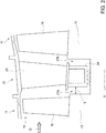
- FIG 2 an enlarged view of a stator assembly 22 between two rotor assemblies 11 in the turbine 5 is shown.
- Arrow D indicates the direction of the hot gas flow flowing in a hot gas channel 18 of the turbine 5.
- inter-assembly cavities 27 are arranged.
- each stator assembly 22 defines a leading inter-assembly cavity 27a and a trailing inter-assembly cavity 27b, wherein the leading inter-assembly cavity 27a is upstream the trailing inter-assembly cavity 27b along the hot gas flow direction D.
- stator ring 24 extends about the longitudinal axis A and comprises an inner edge 28 and an outer edge 29, which is provided with an annular groove 30.
- the plurality of stator vanes 25 are coupled alongside one another to the outer edge 29 of the stator ring 24 so as to close the annular groove 30 and define an annular cooling channel 32.
- the annular cooling channel 32 is fed with air preferably coming from the compressor 3.
- the annular groove 30 defines a leading wall 34 and a trailing wall 35.
- the leading wall 34 is upstream the trailing wall 35 along the hot gas flow direction D.
- leading wall 34 is provided with a plurality of cooling openings 36 in fluidic communication with the annular cooling channel 32.
- the cooling openings 36 are arranged in the proximity of the inner edge 28.
- cooling openings 36 are circumferentially aligned and evenly distributed.
- the trailing wall is provided with the cooling openings in fluidic communication with the annular cooling channel.
- Each stator vane 25 comprises an airfoil 38, an outer shroud 39 and an inner shroud 40 coupled to the stator ring 24.
- the airfoil 38 is provided with a cooling air duct 41a fed by a dedicated opening 41b on the outer shroud 39.
- the outer shroud 39 is coupled to the respective stator casing 9.
- the inner shroud 40 comprises a platform 42, a leading flange 43 and a trailing flange 44 extending radially inward from the platform 42.
- the leading flange 43 is upstream the trailing flange 44 along the hot gas flow direction D.
- leading flange 43 is coupled to the leading wall 34, while the trailing flange 44 is coupled to the trailing wall 35.
- leading flange 43 engages a respective annular seat 46 of the leading wall 34, while the trailing flange 44 engages a respective annular seat 47 of the trailing wall 35.
- leading flange 43 is coupled to the leading wall 34 so as to leave a primary radial gap 48 between the leading wall 34 and the platform 42 and to define a leading surface 50 of the leading flange 43 facing said primary radial gap 48.
- the trailing flange 44 is coupled to the trailing wall 35 so as to leave a secondary radial gap 52 between the trailing wall 35 and the platform 42 and to define a trailing surface 53 of the trailing flange 44 facing said secondary radial gap 52.
- the platform 42 comprises a leading border 54a and a trailing border 54b extending circumferentially.
- the leading border 54a is upstream the trailing border 54b along the hot gas flow direction D.
- the leading flange 43 is provided, on the leading surface 50, with at least one primary cooling hole 55 in fluid communication with the annular cooling channel 32.
- leading flange 43 is provided, on the leading surface 50, with a plurality of primary cooling holes 55 circumferentially aligned.
- the primary cooling holes 55 are evenly distributed.
- each primary cooling hole 55 extends along a primary extension axis Op.
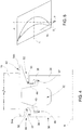
- an angle ⁇ is defined by the projection of the primary extension axis Op on the longitudinal axial plane A-R and the radial direction R.
- the angle ⁇ is measured from the radial direction R to the projection of the primary extension axis Op in accordance with the hot gas flow direction D.
- the angle ⁇ of the primary cooling holes 55 is comprised between 70° and 110°.
- an angle ⁇ is defined by the projection of the primary extension axis O P on the circumferential plane A-C and the axial direction A.
- the angle ⁇ is measured from the axial direction A to the projection of the primary extension axis O P on the tangential plane A-C in a clockwise direction looking radially inward.
- the angle ⁇ is comprised between 100° and 200°.
- the primary cooling holes 55 have different angles ⁇ and/or different angles ⁇ .
- primary cooling holes can be substantially identical to each other.
- leading wall 34 is provided with an annular leading radial face 56 and with an annular leading axial face 57.
- the annular leading axial face 57 of the leading wall 34 is concave with radius of curvature r4.
- the leading border 54a comprises at least one surface 61 facing the primary radial gap 48 and at least one surface 60 facing the air words, the surface 61 faces, in use, the leading inter-assembly cavity 27a and the surface 60 faces the hot gas channel 18.
- the surface 60 and the surface 61 are curved.
- surface 60 and surface 61 are contiguous.
- the surface 60 has a radius of curvature r1 and is convex.
- the surface 61 has a radius of curvature r2 and is convex too.
- the stator assembly 22 comprises also a connecting surface 65, which connects the platform 42 and the leading surface 50.
- the connecting surface 65 is concave with a third radius of curvature r3.
- the connecting surface is not rounded and has a triangular section along the longitudinal axial plane.
- the radius of curvature r1 of the surface 60 is comprised between the 5% and 40% of the distance h between the outer axial surface 59 of the platform and the lower point T of the annular leading axial face 57.
- the radius of curvature r2 of the surface 61 is comprised between the 10% and 50% of the distance h between the outer axial surface 59 of the platform and the lower point T of the annular leading axial face 57.
- the radius of curvature r3 of the connecting surface 65 is comprised between the 20% and 40% of the distance h between the outer axial surface 59 of the platform and the lower point T of the annular leading axial face 57.
- the radius of curvature r4 of the annular leading axial face 57 is comprised between the 45% and 60% of the distance h between the outer axial surface 59 of the platform and the lower point T of the annular leading axial face 57.
- the axial distance s between the outermost point P of the leading border 54a and the outermost point Q of the annular leading axial face 57 is comprised between - 50% and +50% of the axial length L of the leading inter-assembly cavity 27a ( figure 2 ).
- the leading surface 50 has a planar and radially arranged portion arranged radially inward. While the portion of the leading surface 50 arranged radially outward the primary cooling holes 55 and connected to the connecting surface 65 is tangential to the connecting surface 65.
- the hot gas flowing in the hot gas channel 18 is ingested in the leading and flows in to the primary radial gap 48.
- the hot gas ingested flow is first deflected by the leading border 54a, then is forced to recirculate inside the primary radial gap 48 creating a vortex.
- the primary cooling holes 55 cool the hot gas ingested flow and push it back outside the inter-assembly cavity 27a, by energizing the vortex recirculation and exploiting the pumping effect on the rotor side.
- Secondary cooling openings 36 on the leading wall 34 provide also a film-cooling effect on the upper edge of the stator ring 24.
Landscapes
- Engineering & Computer Science (AREA)
- Mechanical Engineering (AREA)
- General Engineering & Computer Science (AREA)
- Physics & Mathematics (AREA)
- Fluid Mechanics (AREA)
- Turbine Rotor Nozzle Sealing (AREA)
Abstract
Description
- The present invention relates to a stator assembly for a gas turbine and to a gas turbine comprising said stator assembly. In particular, the gas turbine of the present invention is part of a plant for the production of electrical energy.
- As is known, a gas turbine for power plants comprises a compressor, a combustor and a turbine.
- In particular, the compressor comprises an inlet supplied with air and a plurality of rotating blades compressing the passing air. The compressed air leaving the compressor flows into a plenum, i.e. a closed volume delimited by an outer casing, and from there into the combustor. Inside the combustor, the compressed air is mixed with at least one fuel and combusted. The resulting hot gas leaves the combustor and expands in the turbine. In the turbine the hot gas expansion moves rotating blades connected to a rotor, performing work.
- Both the compressor and the turbine comprise a plurality of stator assemblies axially interposed between rotor assemblies.
- Each rotor assembly comprises a rotor disk rotating about a main axis and a plurality of blades supported by the rotor disk.
- Each stator assembly comprises a plurality of stator vanes supported by a respective vane carrier and a stator ring arranged about the rotor.
- A plurality of inter-assembly cavities are defined between the stator assemblies and the rotor assemblies.
- In the turbine, sealing air is normally bled from the compressor and introduced in said inter-assembly cavities in order to avoid or limit the hot gas ingestion from the hot gas path in the inter-assemblies cavities.
- The minimization of the amount of air spent to seal and cool the inter-assembly cavities is beneficial to the power plant performance. However, said minimization implies the use of expensive advanced materials and/or the adoption of arrangements having a very complex geometry.
- The object of the present invention is therefore to provide a stator assembly for a gas turbine, which enables avoiding or at least mitigating the described drawbacks.
- In particular, it is an object of the present invention to provide a stator assembly having an improved structure able to minimize the amount of sealing air and guaranteeing, at the same time, a sufficient protection from thermal damages.
- According to said objects the present invention relates to a stator assembly for a gas turbine comprising:
- a stator ring, which extends about a longitudinal axis and comprises an outer edge provided with an annular groove; the annular groove defining a leading wall and a trailing wall; the leading wall being provided with an annular leading radial face and with an annular leading axial face;
- a plurality of stator vanes radially arranged and coupled alongside one another to the outer edge of the stator ring so as to close the annular grove and define an annular cooling channel; each stator vane comprises an airfoil, an outer shroud and an inner shroud coupled to the stator ring; the inner shroud comprising a platform, a leading flange and a trailing flange extending radially inward from the platform; the leading flange being coupled to the leading wall and the trailing flange being coupled to the trailing wall; the leading flange being coupled to the leading wall so as to leave a primary radial gap between the leading wall and the platform and define a leading surface of the leading flange; the platform having a leading border and a trailing border, both extending circumferentially; the leading border comprising at least one first surface facing the primary radial gap; the first surface being curved.
- Advantageously the curved shape of the surface of the leading border facing the primary radial gap deflects the hot gas ingested flow into a confined area: the primary radial gap, where the gas ingested flow can be cooled, managed and washed out again.
- Traditional thin platform leading border, on the contrary, generates a flow separation on the ingested flow that directs hot gases radially down to the bottom part of the leading inter-assembly cavity, with dangerous results for both stator and rotor sides.
- The ingestion of hot gas can therefore be accepted, purged and deflected away. This leads to less overall consumption of sealing air therefore improving the engine global performance and the thermal status and integrity of the components of the stator assembly.
- In other words, instead of completely avoiding hot gas ingestion by using high flow rate of sealing air, the present invention allows to confine hot gas inlet in the upper part of the inter-assembly cavity.
- According to an embodiment of the present invention, the first surface is convex and is curved with a first radius of curvature.
- According to an embodiment of the present invention, the radius of curvature of the surface is comprised between the 10% and 50% of the distance between the outer axial surface of the platform and the lower point of the annular leading axial face.
- According to an embodiment of the present invention, the leading border comprises a second surface facing the airfoil, which is curved.
- According to an embodiment of the present invention, the second surface is convex and is curved with a second radius of curvature.
- According to an embodiment of the present invention, the stator assembly comprises a connecting surface, which connects the platform and the leading surface; the connecting surface being concave with a third radius of curvature.
- In this way, the hot gas ingested is forced to recirculate inside the primary radial gap creating a vortex.
- According to an embodiment of the present invention, the annular leading axial face of the leading wall is concave with a fourth radius of curvature.
- According to an embodiment of the present invention, the leading flange is provided on the leading surface with at least one primary cooling hole in fluid communication with the annular cooling channel.
- The presence of at least primary cooling hole in the leading flange improves the thermal status of the upper part of the inter-assembly leading cavity. In particular, the primary cooling hole improves the thermal status of the annular leading axial face of the leading wall, which is normally made of a material having poorer properties as compared to the vane.
- Instead of providing a lot of air as usually done in the prior art solutions, cooling air is provided where it is more needed.
- According to an embodiment of the present invention, the leading flange is provided with a plurality of primary cooling holes circumferentially aligned, which are preferably evenly distributed.
- According to an embodiment of the present invention, the primary cooling hole extends along a primary extension axis; on a longitudinal axial plane defined by the longitudinal axis and a radial direction orthogonal to the longitudinal axis and intersecting the primary extension axis, a first angle defined by the projection of the primary extension axis on the longitudinal axial plane and the radial direction is comprised between 70° and 110°.
- According to an embodiment of the present invention, the primary cooling hole extends along a primary extension axis; on a circumferential plane defined by the longitudinal axis and a circumferential direction, which is orthogonal to the longitudinal axis and orthogonal to a radial direction in turn orthogonal to the longitudinal axis, a second angle is defined by the projection of the primary extension axis on the circumferential plane and the axial direction is comprised between 100° and 200°.
- It is also an object of the present invention to provide a gas turbine which is reliable and wherein the consumption of sealing air is reduced. According to said objects the present invention relates to a gas turbine as claimed in
claim 15. - The present invention will now be described with reference to the accompanying drawings, which illustrate some non-limitative embodiment, in which:
-
Figure 1 is a schematic sectional front view, with parts removed for clarity, of a gas turbine electric power plant according to the present invention; -
Figure 2 is a schematic sectional front view, with parts removed for clarity, of a first detail ofFigure 1 ; -
Figure 3 is a schematic perspective view, with parts in section and parts removed for clarity, of a second detail ofFigure 1 ; -
Figure 4 is a schematic sectional lateral view, with parts removed for clarity, of a third detail ofFigure 1 ; -
Figure 5 is a schematic up view, with parts in section and parts removed for clarity, of the detail ofFigure 4 ; -
Figure 6 is a schematic sectional lateral view, with parts removed for clarity, of the detail offigure 4 . - In
figure 1 reference numeral 1 indicates a gas turbine electric power plant (schematically shown inFigure 1 ). - The plant 1 comprises a
compressor 3, acombustion chamber 4, agas turbine 5 and a generator (for simplicity, not show in the attached figures). - The
compressor 3,turbine 5 and generator (not shown) are mounted on the same shaft to form arotor 8, which is housed instator casings 9 and extends along an axis A. - In greater detail, the
rotor 8 comprises afront shaft 10, a plurality ofrotor assemblies 11 and arear shaft 13. - Each
rotor assembly 11 comprises arotor disk 15 and a plurality ofrotor blades 16 coupled to therotor disk 15 and radially arranged. - The plurality of
rotor disks 15 are arranged in succession between thefront shaft 10 and therear shaft 13 and preferably clamped as a pack by acentral tie rod 14. As an alternative, the rotor disks may be welded together. - A
central shaft 17 separates therotor disks 15 of thecompressor 3 from therotor disks 15 of theturbine 5 and extends through thecombustion chamber 4. - Further,
stator assemblies 22 are alternated with thecompressor rotor assemblies 11. - Each
stator assembly 22 comprises astator ring 24 and a plurality ofstator vanes 25, which are radially arranged and coupled to thestator ring 24 and to therespective stator casing 9. - In
figure 2 an enlarged view of astator assembly 22 between tworotor assemblies 11 in theturbine 5 is shown. - Arrow D indicates the direction of the hot gas flow flowing in a
hot gas channel 18 of theturbine 5. - Between the
rotor assemblies 11 and thestator assembly 22 inter-assembly cavities 27 are arranged. - In particular, each
stator assembly 22 defines a leadinginter-assembly cavity 27a and a trailinginter-assembly cavity 27b, wherein the leadinginter-assembly cavity 27a is upstream the trailinginter-assembly cavity 27b along the hot gas flow direction D. - With reference to
figure 3 andfigure 4 , the stator ring 24 (only a part of which is visible infigures 3 and4 ) extends about the longitudinal axis A and comprises aninner edge 28 and anouter edge 29, which is provided with anannular groove 30. - The plurality of
stator vanes 25 are coupled alongside one another to theouter edge 29 of thestator ring 24 so as to close theannular groove 30 and define anannular cooling channel 32. - The
annular cooling channel 32 is fed with air preferably coming from thecompressor 3. - The
annular groove 30 defines a leadingwall 34 and a trailingwall 35. The leadingwall 34 is upstream the trailingwall 35 along the hot gas flow direction D. - Preferably, the leading
wall 34 is provided with a plurality of coolingopenings 36 in fluidic communication with theannular cooling channel 32. - Preferably, the cooling
openings 36 are arranged in the proximity of theinner edge 28. - In the non-limiting example here disclosed and illustrated, the cooling
openings 36 are circumferentially aligned and evenly distributed. - According to a variant not illustrated, also the trailing wall is provided with the cooling openings in fluidic communication with the annular cooling channel.
- Each
stator vane 25 comprises anairfoil 38, anouter shroud 39 and aninner shroud 40 coupled to thestator ring 24. - The
airfoil 38 is provided with a coolingair duct 41a fed by adedicated opening 41b on theouter shroud 39. - The
outer shroud 39 is coupled to therespective stator casing 9. - The
inner shroud 40 comprises aplatform 42, a leadingflange 43 and a trailingflange 44 extending radially inward from theplatform 42. The leadingflange 43 is upstream the trailingflange 44 along the hot gas flow direction D. - The leading
flange 43 is coupled to the leadingwall 34, while the trailingflange 44 is coupled to the trailingwall 35. In the non-limiting example here disclosed and illustrated, the leadingflange 43 engages a respectiveannular seat 46 of the leadingwall 34, while the trailingflange 44 engages a respectiveannular seat 47 of the trailingwall 35. - In particular, the leading
flange 43 is coupled to the leadingwall 34 so as to leave aprimary radial gap 48 between the leadingwall 34 and theplatform 42 and to define a leadingsurface 50 of the leadingflange 43 facing saidprimary radial gap 48. - Preferably, also the trailing
flange 44 is coupled to the trailingwall 35 so as to leave a secondaryradial gap 52 between the trailingwall 35 and theplatform 42 and to define a trailingsurface 53 of the trailingflange 44 facing said secondaryradial gap 52. - The
platform 42 comprises a leadingborder 54a and a trailingborder 54b extending circumferentially. The leadingborder 54a is upstream the trailingborder 54b along the hot gas flow direction D. - The leading
flange 43 is provided, on the leadingsurface 50, with at least oneprimary cooling hole 55 in fluid communication with theannular cooling channel 32. - Preferably, the leading
flange 43 is provided, on the leadingsurface 50, with a plurality of primary cooling holes 55 circumferentially aligned. - In the non-limiting example here disclosed and illustrated, the primary cooling holes 55 are evenly distributed.
- With reference to
figure 5 andfigure 6 , eachprimary cooling hole 55 extends along a primary extension axis Op. - With reference to
figure 6 , on a longitudinal axial plane defined by the longitudinal axis A and a radial direction orthogonal to the longitudinal axis A and intersecting the primary extension axis OP, an angle α is defined by the projection of the primary extension axis Op on the longitudinal axial plane A-R and the radial direction R. The angle α is measured from the radial direction R to the projection of the primary extension axis Op in accordance with the hot gas flow direction D. Preferably the angle α of the primary cooling holes 55 is comprised between 70° and 110°. - With reference to
figure 5 on a tangential plane defined by the longitudinal axis A and a circumferential direction C, which is orthogonal to the longitudinal axis A and orthogonal to the radial direction R (in turn orthogonal to the longitudinal axis A) , an angle θ is defined by the projection of the primary extension axis OP on the circumferential plane A-C and the axial direction A. - The angle θ is measured from the axial direction A to the projection of the primary extension axis OP on the tangential plane A-C in a clockwise direction looking radially inward. Preferably, the angle θ is comprised between 100° and 200°.
- Preferably, the primary cooling holes 55 have different angles α and/or different angles θ.
- According to a variant, primary cooling holes can be substantially identical to each other.
- With reference to
figure 3 ,4 and6 , the leadingwall 34 is provided with an annular leadingradial face 56 and with an annular leadingaxial face 57. - Preferably, the annular leading
axial face 57 of the leadingwall 34 is concave with radius of curvature r4. - With particular reference to
figure 6 , the leadingborder 54a comprises at least onesurface 61 facing theprimary radial gap 48 and at least onesurface 60 facing the air words, thesurface 61 faces, in use, the leadinginter-assembly cavity 27a and thesurface 60 faces thehot gas channel 18. - Preferably, the
surface 60 and thesurface 61 are curved. - Preferably,
surface 60 andsurface 61 are contiguous. - Preferably, the
surface 60 has a radius of curvature r1 and is convex. - Preferably, the
surface 61 has a radius of curvature r2 and is convex too. - The
stator assembly 22 comprises also a connectingsurface 65, which connects theplatform 42 and the leadingsurface 50. Preferably, the connectingsurface 65 is concave with a third radius of curvature r3. - According to a variant not illustrated, the connecting surface is not rounded and has a triangular section along the longitudinal axial plane.
- Preferably, the radius of curvature r1 of the
surface 60 is comprised between the 5% and 40% of the distance h between the outeraxial surface 59 of the platform and the lower point T of the annular leadingaxial face 57. - Preferably, the radius of curvature r2 of the
surface 61 is comprised between the 10% and 50% of the distance h between the outeraxial surface 59 of the platform and the lower point T of the annular leadingaxial face 57. - Preferably, the radius of curvature r3 of the connecting
surface 65 is comprised between the 20% and 40% of the distance h between the outeraxial surface 59 of the platform and the lower point T of the annular leadingaxial face 57. - Preferably, the radius of curvature r4 of the annular leading
axial face 57 is comprised between the 45% and 60% of the distance h between the outeraxial surface 59 of the platform and the lower point T of the annular leadingaxial face 57. - Preferably the axial distance s between the outermost point P of the leading
border 54a and the outermost point Q of the annular leadingaxial face 57 is comprised between - 50% and +50% of the axial length L of the leadinginter-assembly cavity 27a (figure 2 ). - Preferably the leading
surface 50 has a planar and radially arranged portion arranged radially inward. While the portion of the leadingsurface 50 arranged radially outward the primary cooling holes 55 and connected to the connectingsurface 65 is tangential to the connectingsurface 65. - In use, the hot gas flowing in the
hot gas channel 18 is ingested in the leading and flows in to theprimary radial gap 48. In particular, the hot gas ingested flow is first deflected by the leadingborder 54a, then is forced to recirculate inside theprimary radial gap 48 creating a vortex. - The primary cooling holes 55 cool the hot gas ingested flow and push it back outside the
inter-assembly cavity 27a, by energizing the vortex recirculation and exploiting the pumping effect on the rotor side.Secondary cooling openings 36 on the leadingwall 34 provide also a film-cooling effect on the upper edge of thestator ring 24. - Finally, it is clear that modifications and variants can be made to the stator assembly and to the gas turbine described herein without departing from the scope of the present invention, as defined in the appended claims.
Claims (15)
- Stator assembly (22) for a gas turbine comprising:a stator ring (24), which extends about a longitudinal axis (A) and comprises an outer edge (29) provided with an annular groove (30); the annular groove (30) defining a leading wall (34) and a trailing wall (35); the leading wall (34) being provided with an annular leading radial face (56) and with an annular leading axial face (57);a plurality of stator vanes (25) radially arranged and coupled alongside one another to the outer edge (29) of the stator ring (24) so as to close the annular grove (30) and define an annular cooling channel (32); each stator vane (25) comprises an airfoil (38), an outer shroud (39) and an inner shroud (40) coupled to the stator ring (24); the inner shroud (40) comprising a platform (42), a leading flange (43) and a trailing flange (44) extending radially inward from the platform (42); the leading flange (43) being coupled to the leading wall (34) and the trailing flange (44) being coupled to the trailing wall (35); the leading flange (43) being coupled to the leading wall (34) so as to leave a primary radial gap (48) between the leading wall (34) and the platform (42) and define a leading surface (50) of the leading flange (43); the platform (42) having a leading border (54a) and a trailing border (54b), both extending circumferentially; the leading border (54a) comprising at least one first surface (61) facing the primary radial gap (48); the first surface (61) being curved.
- Stator according to claim 1, wherein the first surface (61) is convex.
- Stator assembly according to claim 2, wherein the first surface (61) is curved with a first radius of curvature (r2) .
- Stator assembly according to claim 3, wherein the radius of curvature (r2) of the surface (61) is comprised between the 10% and 50% of the distance (h) between the outer axial surface (59) of the platform and the lower point (T) of the annular leading axial face (57).
- Stator assembly according to anyone of the foregoing claims, wherein the leading border (54a) comprises a second surface (60) facing the airfoil (18), which is curved.
- Stator according to claim 5, wherein the second surface (60) is convex.
- Stator assembly according to claim 6, wherein the second surface (60) is curved with a second radius of curvature (r1).
- Stator assembly according to anyone of the foregoing claims, comprising a connecting surface (65), which connects the platform (42) and the leading surface (50); the connecting surface (65) being concave with a third radius of curvature (r3) .
- Stator assembly according to anyone of the foregoing claims, wherein the annular leading axial face (57) of the leading wall (34) is concave with a fourth radius of curvature (r4) .
- Stator assembly according to anyone of the foregoing claims, wherein the leading flange (43) is provided on the leading surface (50) with at least one primary cooling hole (55) in fluid communication with the annular cooling channel (32) .
- Stator assembly according to anyone of the foregoing claims, wherein the leading flange (43) is provided on the leading surface (50) with a plurality of primary cooling holes (55) circumferentially aligned.
- Stator assembly according to claim 11, wherein the primary cooling holes (55) are evenly distributed.
- Stator assembly according to anyone of the foregoing claims, wherein the primary cooling hole (55) extends along a primary extension axis (Op); on a longitudinal axial plane (A-R) defined by the longitudinal axis (A) and a radial direction (R) orthogonal to the longitudinal axis (A) and intersecting the primary extension axis (OP) , a first angle (α) defined by the projection of the primary extension axis (Op) on the longitudinal axial plane (A-R) and the radial direction (R) is comprised between 70° and 110°.
- Stator assembly according to anyone of the foregoing claims, wherein the primary cooling hole (55) extends along a primary extension axis (Op); on a circumferential plane defined by the longitudinal axis (A) and a circumferential direction (C) , which is orthogonal to the longitudinal axis (A) and orthogonal to a radial direction (R) in turn orthogonal to the longitudinal axis (A), a second angle (θ) is defined by the projection of the primary extension axis (Op) on the circumferential plane and the axial direction (A) is comprised between 100° and 200°.
- Gas turbine extending along a longitudinal axis (A) and comprising:a plurality of rotor assemblies (11), each of which comprises a rotor disk (15) and a plurality of rotor blades (16) radially arranged and coupled to the rotor disk (15);a plurality of stator assemblies (22); the stator assemblies (22) and the rotor assemblies (11) are alternated along the axial direction (A);at least one of the stator assemblies (22) being of the type claimed in anyone of the foregoing claims.
Priority Applications (2)
| Application Number | Priority Date | Filing Date | Title |
|---|---|---|---|
| EP19425078.3A EP3816402B1 (en) | 2019-11-04 | 2019-11-04 | Stator assembly for a gas turbine and gas turbine comprising said stator assembly |
| CN202011217289.4A CN112780359B (en) | 2019-11-04 | 2020-11-04 | Stator assembly for a gas turbine and gas turbine comprising said stator assembly |
Applications Claiming Priority (1)
| Application Number | Priority Date | Filing Date | Title |
|---|---|---|---|
| EP19425078.3A EP3816402B1 (en) | 2019-11-04 | 2019-11-04 | Stator assembly for a gas turbine and gas turbine comprising said stator assembly |
Publications (2)
| Publication Number | Publication Date |
|---|---|
| EP3816402A1 true EP3816402A1 (en) | 2021-05-05 |
| EP3816402B1 EP3816402B1 (en) | 2023-01-04 |
Family
ID=68887365
Family Applications (1)
| Application Number | Title | Priority Date | Filing Date |
|---|---|---|---|
| EP19425078.3A Active EP3816402B1 (en) | 2019-11-04 | 2019-11-04 | Stator assembly for a gas turbine and gas turbine comprising said stator assembly |
Country Status (2)
| Country | Link |
|---|---|
| EP (1) | EP3816402B1 (en) |
| CN (1) | CN112780359B (en) |
Citations (4)
| Publication number | Priority date | Publication date | Assignee | Title |
|---|---|---|---|---|
| US6481959B1 (en) * | 2001-04-26 | 2002-11-19 | Honeywell International, Inc. | Gas turbine disk cavity ingestion inhibitor |
| US20100008760A1 (en) * | 2008-07-10 | 2010-01-14 | Honeywell International Inc. | Gas turbine engine assemblies with recirculated hot gas ingestion |
| US9062557B2 (en) * | 2011-09-07 | 2015-06-23 | Siemens Aktiengesellschaft | Flow discourager integrated turbine inter-stage U-ring |
| WO2015104695A1 (en) * | 2014-01-13 | 2015-07-16 | Ansaldo Energia S.P.A. | Blade for a gas turbine and method for manufacturing said blade |
Family Cites Families (1)
| Publication number | Priority date | Publication date | Assignee | Title |
|---|---|---|---|---|
| US6431820B1 (en) * | 2001-02-28 | 2002-08-13 | General Electric Company | Methods and apparatus for cooling gas turbine engine blade tips |
-
2019
- 2019-11-04 EP EP19425078.3A patent/EP3816402B1/en active Active
-
2020
- 2020-11-04 CN CN202011217289.4A patent/CN112780359B/en active Active
Patent Citations (4)
| Publication number | Priority date | Publication date | Assignee | Title |
|---|---|---|---|---|
| US6481959B1 (en) * | 2001-04-26 | 2002-11-19 | Honeywell International, Inc. | Gas turbine disk cavity ingestion inhibitor |
| US20100008760A1 (en) * | 2008-07-10 | 2010-01-14 | Honeywell International Inc. | Gas turbine engine assemblies with recirculated hot gas ingestion |
| US9062557B2 (en) * | 2011-09-07 | 2015-06-23 | Siemens Aktiengesellschaft | Flow discourager integrated turbine inter-stage U-ring |
| WO2015104695A1 (en) * | 2014-01-13 | 2015-07-16 | Ansaldo Energia S.P.A. | Blade for a gas turbine and method for manufacturing said blade |
Also Published As
| Publication number | Publication date |
|---|---|
| CN112780359B (en) | 2025-06-10 |
| EP3816402B1 (en) | 2023-01-04 |
| CN112780359A (en) | 2021-05-11 |
Similar Documents
| Publication | Publication Date | Title |
|---|---|---|
| CN205744004U (en) | Combustion gas turbine | |
| US8118548B2 (en) | Shroud for a turbomachine | |
| US8573925B2 (en) | Cooled component for a gas turbine engine | |
| US9771820B2 (en) | Gas turbine sealing | |
| US9366148B2 (en) | Assembly of an axial turbomachine and method for manufacturing an assembly of this type | |
| CN104246140A (en) | Turbine nozzle outer band and airfoil cooling apparatus | |
| JP2015086872A (en) | Microchannel exhaust for cooling and/or purging gas turbine segment gaps | |
| CN103075198A (en) | Turbine bucket platform leading edge and related method | |
| CN107076028A (en) | Containment member | |
| US20170175557A1 (en) | Gas turbine sealing | |
| CN103670529B (en) | For cooling method and the cooling system of the blade of at least one blade row | |
| EP3663522B1 (en) | Stator assembly for a gas turbine and gas turbine comprising said stator assembly | |
| CN107461225A (en) | Nozzle cooling system for gas-turbine unit | |
| CN106194276A (en) | Compressor Systems and Airfoil Assemblies | |
| EP4230844B1 (en) | Stator assembly for a gas turbine and gas turbine comprising said stator assembly | |
| EP3816402B1 (en) | Stator assembly for a gas turbine and gas turbine comprising said stator assembly | |
| CN108999647B (en) | Turbomachine rotor blade | |
| KR102494020B1 (en) | Turbomachine component for a gas turbine, turbomachine assembly and gas turbine having the same | |
| US10738638B2 (en) | Rotor blade with wheel space swirlers and method for forming a rotor blade with wheel space swirlers | |
| EP4206441B1 (en) | Stator assembly for a compressor of a gas turbine assembly and compressor for a gas turbine assembly | |
| US20260028914A1 (en) | Turbine module for a turbomachine | |
| US11536158B2 (en) | Turbomachine |
Legal Events
| Date | Code | Title | Description |
|---|---|---|---|
| PUAI | Public reference made under article 153(3) epc to a published international application that has entered the european phase |
Free format text: ORIGINAL CODE: 0009012 |
|
| STAA | Information on the status of an ep patent application or granted ep patent |
Free format text: STATUS: THE APPLICATION HAS BEEN PUBLISHED |
|
| AK | Designated contracting states |
Kind code of ref document: A1 Designated state(s): AL AT BE BG CH CY CZ DE DK EE ES FI FR GB GR HR HU IE IS IT LI LT LU LV MC MK MT NL NO PL PT RO RS SE SI SK SM TR |
|
| STAA | Information on the status of an ep patent application or granted ep patent |
Free format text: STATUS: REQUEST FOR EXAMINATION WAS MADE |
|
| 17P | Request for examination filed |
Effective date: 20211105 |
|
| RBV | Designated contracting states (corrected) |
Designated state(s): AL AT BE BG CH CY CZ DE DK EE ES FI FR GB GR HR HU IE IS IT LI LT LU LV MC MK MT NL NO PL PT RO RS SE SI SK SM TR |
|
| GRAP | Despatch of communication of intention to grant a patent |
Free format text: ORIGINAL CODE: EPIDOSNIGR1 |
|
| STAA | Information on the status of an ep patent application or granted ep patent |
Free format text: STATUS: GRANT OF PATENT IS INTENDED |
|
| GRAJ | Information related to disapproval of communication of intention to grant by the applicant or resumption of examination proceedings by the epo deleted |
Free format text: ORIGINAL CODE: EPIDOSDIGR1 |
|
| STAA | Information on the status of an ep patent application or granted ep patent |
Free format text: STATUS: REQUEST FOR EXAMINATION WAS MADE |
|
| INTG | Intention to grant announced |
Effective date: 20220323 |
|
| INTC | Intention to grant announced (deleted) | ||
| GRAP | Despatch of communication of intention to grant a patent |
Free format text: ORIGINAL CODE: EPIDOSNIGR1 |
|
| STAA | Information on the status of an ep patent application or granted ep patent |
Free format text: STATUS: GRANT OF PATENT IS INTENDED |
|
| INTG | Intention to grant announced |
Effective date: 20220608 |
|
| GRAS | Grant fee paid |
Free format text: ORIGINAL CODE: EPIDOSNIGR3 |
|
| GRAA | (expected) grant |
Free format text: ORIGINAL CODE: 0009210 |
|
| STAA | Information on the status of an ep patent application or granted ep patent |
Free format text: STATUS: THE PATENT HAS BEEN GRANTED |
|
| AK | Designated contracting states |
Kind code of ref document: B1 Designated state(s): AL AT BE BG CH CY CZ DE DK EE ES FI FR GB GR HR HU IE IS IT LI LT LU LV MC MK MT NL NO PL PT RO RS SE SI SK SM TR |
|
| REG | Reference to a national code |
Ref country code: GB Ref legal event code: FG4D |
|
| REG | Reference to a national code |
Ref country code: CH Ref legal event code: EP |
|
| REG | Reference to a national code |
Ref country code: AT Ref legal event code: REF Ref document number: 1542053 Country of ref document: AT Kind code of ref document: T Effective date: 20230115 |
|
| REG | Reference to a national code |
Ref country code: DE Ref legal event code: R096 Ref document number: 602019023938 Country of ref document: DE |
|
| REG | Reference to a national code |
Ref country code: IE Ref legal event code: FG4D |
|
| REG | Reference to a national code |
Ref country code: LT Ref legal event code: MG9D |
|
| REG | Reference to a national code |
Ref country code: NL Ref legal event code: MP Effective date: 20230104 |
|
| REG | Reference to a national code |
Ref country code: AT Ref legal event code: MK05 Ref document number: 1542053 Country of ref document: AT Kind code of ref document: T Effective date: 20230104 |
|
| PG25 | Lapsed in a contracting state [announced via postgrant information from national office to epo] |
Ref country code: NL Free format text: LAPSE BECAUSE OF FAILURE TO SUBMIT A TRANSLATION OF THE DESCRIPTION OR TO PAY THE FEE WITHIN THE PRESCRIBED TIME-LIMIT Effective date: 20230104 |
|
| PG25 | Lapsed in a contracting state [announced via postgrant information from national office to epo] |
Ref country code: RS Free format text: LAPSE BECAUSE OF FAILURE TO SUBMIT A TRANSLATION OF THE DESCRIPTION OR TO PAY THE FEE WITHIN THE PRESCRIBED TIME-LIMIT Effective date: 20230104 Ref country code: PT Free format text: LAPSE BECAUSE OF FAILURE TO SUBMIT A TRANSLATION OF THE DESCRIPTION OR TO PAY THE FEE WITHIN THE PRESCRIBED TIME-LIMIT Effective date: 20230504 Ref country code: NO Free format text: LAPSE BECAUSE OF FAILURE TO SUBMIT A TRANSLATION OF THE DESCRIPTION OR TO PAY THE FEE WITHIN THE PRESCRIBED TIME-LIMIT Effective date: 20230404 Ref country code: LV Free format text: LAPSE BECAUSE OF FAILURE TO SUBMIT A TRANSLATION OF THE DESCRIPTION OR TO PAY THE FEE WITHIN THE PRESCRIBED TIME-LIMIT Effective date: 20230104 Ref country code: LT Free format text: LAPSE BECAUSE OF FAILURE TO SUBMIT A TRANSLATION OF THE DESCRIPTION OR TO PAY THE FEE WITHIN THE PRESCRIBED TIME-LIMIT Effective date: 20230104 Ref country code: HR Free format text: LAPSE BECAUSE OF FAILURE TO SUBMIT A TRANSLATION OF THE DESCRIPTION OR TO PAY THE FEE WITHIN THE PRESCRIBED TIME-LIMIT Effective date: 20230104 Ref country code: ES Free format text: LAPSE BECAUSE OF FAILURE TO SUBMIT A TRANSLATION OF THE DESCRIPTION OR TO PAY THE FEE WITHIN THE PRESCRIBED TIME-LIMIT Effective date: 20230104 Ref country code: AT Free format text: LAPSE BECAUSE OF FAILURE TO SUBMIT A TRANSLATION OF THE DESCRIPTION OR TO PAY THE FEE WITHIN THE PRESCRIBED TIME-LIMIT Effective date: 20230104 |
|
| PG25 | Lapsed in a contracting state [announced via postgrant information from national office to epo] |
Ref country code: SE Free format text: LAPSE BECAUSE OF FAILURE TO SUBMIT A TRANSLATION OF THE DESCRIPTION OR TO PAY THE FEE WITHIN THE PRESCRIBED TIME-LIMIT Effective date: 20230104 Ref country code: PL Free format text: LAPSE BECAUSE OF FAILURE TO SUBMIT A TRANSLATION OF THE DESCRIPTION OR TO PAY THE FEE WITHIN THE PRESCRIBED TIME-LIMIT Effective date: 20230104 Ref country code: IS Free format text: LAPSE BECAUSE OF FAILURE TO SUBMIT A TRANSLATION OF THE DESCRIPTION OR TO PAY THE FEE WITHIN THE PRESCRIBED TIME-LIMIT Effective date: 20230504 Ref country code: GR Free format text: LAPSE BECAUSE OF FAILURE TO SUBMIT A TRANSLATION OF THE DESCRIPTION OR TO PAY THE FEE WITHIN THE PRESCRIBED TIME-LIMIT Effective date: 20230405 Ref country code: FI Free format text: LAPSE BECAUSE OF FAILURE TO SUBMIT A TRANSLATION OF THE DESCRIPTION OR TO PAY THE FEE WITHIN THE PRESCRIBED TIME-LIMIT Effective date: 20230104 |
|
| REG | Reference to a national code |
Ref country code: DE Ref legal event code: R097 Ref document number: 602019023938 Country of ref document: DE |
|
| PG25 | Lapsed in a contracting state [announced via postgrant information from national office to epo] |
Ref country code: SM Free format text: LAPSE BECAUSE OF FAILURE TO SUBMIT A TRANSLATION OF THE DESCRIPTION OR TO PAY THE FEE WITHIN THE PRESCRIBED TIME-LIMIT Effective date: 20230104 Ref country code: RO Free format text: LAPSE BECAUSE OF FAILURE TO SUBMIT A TRANSLATION OF THE DESCRIPTION OR TO PAY THE FEE WITHIN THE PRESCRIBED TIME-LIMIT Effective date: 20230104 Ref country code: EE Free format text: LAPSE BECAUSE OF FAILURE TO SUBMIT A TRANSLATION OF THE DESCRIPTION OR TO PAY THE FEE WITHIN THE PRESCRIBED TIME-LIMIT Effective date: 20230104 Ref country code: DK Free format text: LAPSE BECAUSE OF FAILURE TO SUBMIT A TRANSLATION OF THE DESCRIPTION OR TO PAY THE FEE WITHIN THE PRESCRIBED TIME-LIMIT Effective date: 20230104 Ref country code: CZ Free format text: LAPSE BECAUSE OF FAILURE TO SUBMIT A TRANSLATION OF THE DESCRIPTION OR TO PAY THE FEE WITHIN THE PRESCRIBED TIME-LIMIT Effective date: 20230104 |
|
| PLBE | No opposition filed within time limit |
Free format text: ORIGINAL CODE: 0009261 |
|
| STAA | Information on the status of an ep patent application or granted ep patent |
Free format text: STATUS: NO OPPOSITION FILED WITHIN TIME LIMIT |
|
| PG25 | Lapsed in a contracting state [announced via postgrant information from national office to epo] |
Ref country code: SK Free format text: LAPSE BECAUSE OF FAILURE TO SUBMIT A TRANSLATION OF THE DESCRIPTION OR TO PAY THE FEE WITHIN THE PRESCRIBED TIME-LIMIT Effective date: 20230104 |
|
| 26N | No opposition filed |
Effective date: 20231005 |
|
| PG25 | Lapsed in a contracting state [announced via postgrant information from national office to epo] |
Ref country code: SI Free format text: LAPSE BECAUSE OF FAILURE TO SUBMIT A TRANSLATION OF THE DESCRIPTION OR TO PAY THE FEE WITHIN THE PRESCRIBED TIME-LIMIT Effective date: 20230104 |
|
| P01 | Opt-out of the competence of the unified patent court (upc) registered |
Effective date: 20240430 |
|
| REG | Reference to a national code |
Ref country code: CH Ref legal event code: PL |
|
| PG25 | Lapsed in a contracting state [announced via postgrant information from national office to epo] |
Ref country code: MC Free format text: LAPSE BECAUSE OF FAILURE TO SUBMIT A TRANSLATION OF THE DESCRIPTION OR TO PAY THE FEE WITHIN THE PRESCRIBED TIME-LIMIT Effective date: 20230104 |
|
| PG25 | Lapsed in a contracting state [announced via postgrant information from national office to epo] |
Ref country code: LU Free format text: LAPSE BECAUSE OF NON-PAYMENT OF DUE FEES Effective date: 20231104 |
|
| PG25 | Lapsed in a contracting state [announced via postgrant information from national office to epo] |
Ref country code: CH Free format text: LAPSE BECAUSE OF NON-PAYMENT OF DUE FEES Effective date: 20231130 |
|
| PG25 | Lapsed in a contracting state [announced via postgrant information from national office to epo] |
Ref country code: MC Free format text: LAPSE BECAUSE OF FAILURE TO SUBMIT A TRANSLATION OF THE DESCRIPTION OR TO PAY THE FEE WITHIN THE PRESCRIBED TIME-LIMIT Effective date: 20230104 Ref country code: LU Free format text: LAPSE BECAUSE OF NON-PAYMENT OF DUE FEES Effective date: 20231104 Ref country code: CH Free format text: LAPSE BECAUSE OF NON-PAYMENT OF DUE FEES Effective date: 20231130 |
|
| REG | Reference to a national code |
Ref country code: BE Ref legal event code: MM Effective date: 20231130 |
|
| REG | Reference to a national code |
Ref country code: IE Ref legal event code: MM4A |
|
| PG25 | Lapsed in a contracting state [announced via postgrant information from national office to epo] |
Ref country code: IE Free format text: LAPSE BECAUSE OF NON-PAYMENT OF DUE FEES Effective date: 20231104 |
|
| PG25 | Lapsed in a contracting state [announced via postgrant information from national office to epo] |
Ref country code: BE Free format text: LAPSE BECAUSE OF NON-PAYMENT OF DUE FEES Effective date: 20231130 |
|
| PG25 | Lapsed in a contracting state [announced via postgrant information from national office to epo] |
Ref country code: FR Free format text: LAPSE BECAUSE OF NON-PAYMENT OF DUE FEES Effective date: 20231130 |
|
| PG25 | Lapsed in a contracting state [announced via postgrant information from national office to epo] |
Ref country code: IE Free format text: LAPSE BECAUSE OF NON-PAYMENT OF DUE FEES Effective date: 20231104 Ref country code: FR Free format text: LAPSE BECAUSE OF NON-PAYMENT OF DUE FEES Effective date: 20231130 Ref country code: BE Free format text: LAPSE BECAUSE OF NON-PAYMENT OF DUE FEES Effective date: 20231130 |
|
| PG25 | Lapsed in a contracting state [announced via postgrant information from national office to epo] |
Ref country code: BG Free format text: LAPSE BECAUSE OF FAILURE TO SUBMIT A TRANSLATION OF THE DESCRIPTION OR TO PAY THE FEE WITHIN THE PRESCRIBED TIME-LIMIT Effective date: 20230104 |
|
| PG25 | Lapsed in a contracting state [announced via postgrant information from national office to epo] |
Ref country code: BG Free format text: LAPSE BECAUSE OF FAILURE TO SUBMIT A TRANSLATION OF THE DESCRIPTION OR TO PAY THE FEE WITHIN THE PRESCRIBED TIME-LIMIT Effective date: 20230104 |
|
| PG25 | Lapsed in a contracting state [announced via postgrant information from national office to epo] |
Ref country code: CY Free format text: LAPSE BECAUSE OF FAILURE TO SUBMIT A TRANSLATION OF THE DESCRIPTION OR TO PAY THE FEE WITHIN THE PRESCRIBED TIME-LIMIT; INVALID AB INITIO Effective date: 20191104 |
|
| PG25 | Lapsed in a contracting state [announced via postgrant information from national office to epo] |
Ref country code: HU Free format text: LAPSE BECAUSE OF FAILURE TO SUBMIT A TRANSLATION OF THE DESCRIPTION OR TO PAY THE FEE WITHIN THE PRESCRIBED TIME-LIMIT; INVALID AB INITIO Effective date: 20191104 |
|
| PG25 | Lapsed in a contracting state [announced via postgrant information from national office to epo] |
Ref country code: TR Free format text: LAPSE BECAUSE OF FAILURE TO SUBMIT A TRANSLATION OF THE DESCRIPTION OR TO PAY THE FEE WITHIN THE PRESCRIBED TIME-LIMIT Effective date: 20230104 |
|
| PGFP | Annual fee paid to national office [announced via postgrant information from national office to epo] |
Ref country code: DE Payment date: 20251118 Year of fee payment: 7 |
|
| PGFP | Annual fee paid to national office [announced via postgrant information from national office to epo] |
Ref country code: GB Payment date: 20251120 Year of fee payment: 7 |
|
| PGFP | Annual fee paid to national office [announced via postgrant information from national office to epo] |
Ref country code: IT Payment date: 20251128 Year of fee payment: 7 |