EP3816362A1 - Support for panel with side blocking device - Google Patents
Support for panel with side blocking device Download PDFInfo
- Publication number
- EP3816362A1 EP3816362A1 EP20204433.5A EP20204433A EP3816362A1 EP 3816362 A1 EP3816362 A1 EP 3816362A1 EP 20204433 A EP20204433 A EP 20204433A EP 3816362 A1 EP3816362 A1 EP 3816362A1
- Authority
- EP
- European Patent Office
- Prior art keywords
- panel
- flank
- support
- cradle
- seat
- Prior art date
- Legal status (The legal status is an assumption and is not a legal conclusion. Google has not performed a legal analysis and makes no representation as to the accuracy of the status listed.)
- Granted
Links
Images





Classifications
-
- E—FIXED CONSTRUCTIONS
- E04—BUILDING
- E04F—FINISHING WORK ON BUILDINGS, e.g. STAIRS, FLOORS
- E04F11/00—Stairways, ramps, or like structures; Balustrades; Handrails
- E04F11/18—Balustrades; Handrails
- E04F11/181—Balustrades
- E04F11/1817—Connections therefor
- E04F11/1834—Connections therefor with adjustable angle, e.g. pivotal connections
-
- E—FIXED CONSTRUCTIONS
- E04—BUILDING
- E04F—FINISHING WORK ON BUILDINGS, e.g. STAIRS, FLOORS
- E04F11/00—Stairways, ramps, or like structures; Balustrades; Handrails
- E04F11/18—Balustrades; Handrails
- E04F11/181—Balustrades
- E04F11/1817—Connections therefor
-
- E—FIXED CONSTRUCTIONS
- E04—BUILDING
- E04F—FINISHING WORK ON BUILDINGS, e.g. STAIRS, FLOORS
- E04F11/00—Stairways, ramps, or like structures; Balustrades; Handrails
- E04F11/18—Balustrades; Handrails
- E04F11/181—Balustrades
- E04F11/1851—Filling panels, e.g. concrete, sheet metal panels
- E04F11/1853—Glass panels
-
- E—FIXED CONSTRUCTIONS
- E04—BUILDING
- E04F—FINISHING WORK ON BUILDINGS, e.g. STAIRS, FLOORS
- E04F11/00—Stairways, ramps, or like structures; Balustrades; Handrails
- E04F11/18—Balustrades; Handrails
- E04F11/181—Balustrades
- E04F11/1817—Connections therefor
- E04F2011/1823—Connections therefor between balustrade filling members, e.g. balusters or panels, and horizontal or sloping balustrade members
-
- F—MECHANICAL ENGINEERING; LIGHTING; HEATING; WEAPONS; BLASTING
- F16—ENGINEERING ELEMENTS AND UNITS; GENERAL MEASURES FOR PRODUCING AND MAINTAINING EFFECTIVE FUNCTIONING OF MACHINES OR INSTALLATIONS; THERMAL INSULATION IN GENERAL
- F16B—DEVICES FOR FASTENING OR SECURING CONSTRUCTIONAL ELEMENTS OR MACHINE PARTS TOGETHER, e.g. NAILS, BOLTS, CIRCLIPS, CLAMPS, CLIPS OR WEDGES; JOINTS OR JOINTING
- F16B2/00—Friction-grip releasable fastenings
- F16B2/02—Clamps, i.e. with gripping action effected by positive means other than the inherent resistance to deformation of the material of the fastening
- F16B2/14—Clamps, i.e. with gripping action effected by positive means other than the inherent resistance to deformation of the material of the fastening using wedges
Definitions
- the present inventions relates to equipment for fastening, and supporting, structural or complementary panels in building industry, such as glazed frames, parapets, separating elements, etc.
- the invention relates to a support for a panel, especially, even if not exclusively, for a glazed panel, for walls, separating walls, parapets, etc.
- a type of support provides for a base, defining an open seat where the edge area of the panel is housed, and for a device, interposed between the panel and the base, for blocking the panel, or adjusting the inclination thereof, with respect to the base.
- An example of support is disclosed in the patent application no. WO2019162825 , of the same Applicant.
- the disclosed support is particularly innovative and is greatly appreciated by the market; however, as other known supports, it requires adjustments at both sides of the panel.
- the object of the invention is to overcome the drawbacks of the prior art supports for panels.
- an important object of the invention is to provide a support for a panel, especially, although not exclusively, for a glazed panel, allowing easy installation and adjustment of the panel by acting on only one side of the system.
- a further important object of the invention is to provide a support for a panel, especially, although not exclusively, for a glazed panel, allowing the panel to be easily blocked.
- a further important object of the invention is to provide a support for a panel, especially, although not exclusively, for a glazed panel, allowing to block the panel in a stable and durable way.
- a support for a panel comprising:
- the flank side element of the cradle is made as a separate and distinct piece with respect to the bottom; preferably, the cradle comprises a rest body, on which the bottom for the edge of the panel is defined; Preferably, at least one flank of the cradle, opposite to the flank side element, extends from the bottom; preferably the flank of the cradle opposite the flank side element is less high, from the underside of the seat towards the opening thereof, than the flank side element, and more preferably it is high less than half the height of the flank side element.
- a first flank and a second flank for containing the edge of the panel, extend opposite each other from the bottom.
- the first flank preferably comprises two portions projecting upwards and longitudinally spaced from each other to define a side space, where the flank side element is arranged; the first flank preferably has discontinuous surfaces of contact with the panel.
- the first side of the base comprises a longitudinal rib projecting towards the opposite side, against which the flank side element abuts.
- the first flank abuts against the longitudinal rib.
- the at least one abutment element comprises a longitudinal gasket fixed to the second side of the base or to an additional element fixed on the base in correspondence of, or in proximity to, this second side.
- the at least one abutment element may comprise parts directly defined on the second side of the base, and may be not necessarily a gasket (for example, it may be defined by a portion of the same base).
- the support comprises a device for longitudinal closing the portion of the opening of the said base defined on the side of the first side when the panel is inserted into the base;
- the longitudinal closing device preferably comprises a longitudinal gasket adapted to come into contact with the panel;
- the longitudinal closing device preferably comprises a longitudinal section bar coupled to the end of the first side, this longitudinal gasket adapted to come into contact with the panel being fastened to the section bar.
- the flank side element defines a sliding guide for the at least one wedge-shaped element.
- the wedge-shaped element comprises two wedge-shaped portions spaced from each other, and the hole for the adjustment screw is provided in the space between the two wedge-shaped portions, two intermediate blocking elements being provided, each of which is adapted to interact with a respective wedge-shaped portion.
- the at least one intermediate blocking element is cylindrical in shape.
- the undercut portion of the first side of the seat has a curved shape, with preferably constant radius; the at least one intermediate blocking element has preferably an abutment surface for the undercut portion, whose shape is substantially complementary to that of the undercut portion.
- the first side comprising the undercut portion has a segment inclined from the inside towards the outside of the seat, making reference to the direction from the seat underside to the opening, the segment being connected to the undercut.
- the distance, measured again in correspondence of the seat opening, between the sides and the respective surfaces facing the sides of the panel is such that the distance between the first side and the panel is greater than that between the second side and the panel.
- the seat is preferably asymmetrical with respect to a longitudinal vertical plane passing through the centerline of the base, calculated with respect to the outside of the base.
- the first side has at least one segment whose inclination is greater than that of any opposite second side; the seat is therefore more flared upwards in correspondence of the first side with respect to the second side.
- the support comprises an apparatus for transversally displacing the edge area of the panel, this resulting in a change in the vertical inclination of the same panel.
- the displacement apparatus preferably comprises at least a movable body interposed between the second surface of the panel and the cradle portion opposite the flank side element, the movable body being adapted to take more positions or configurations, to each of which corresponds a different distance between the edge area of the panel and the second side.
- the movable body is kinematically connected to an element for controlling the movement thereof, which can be preferably actuated through a tool that is preferably inserted in the seat of the base through the opening.
- the movable body has preferably variable thickness, more preferably it is of the wedge-type, i.e. it has two opposite operating faces inclined relative to each other, wherein the first operating face of the wedge-shaped movable body is in contact with the second surface of the panel, and the opposite second operating face moves on the cradle portion opposite the flank side element.
- the interface surface of mutual sliding between the cradle portion opposite the flank side element and the movable body is preferably inclined with respect to the direction of longitudinal extension of the housing seat of the panel, so that the movable body, moving along the inclined interface surface, changes its transverse position inside the seat, therefore inside the cradle, i.e. it moves away from, or towards, the sides of the seat;
- the movable body is preferably of the wedge-type, with an operating face always parallel to, and in contact with, the second surface of the panel.
- the movable body preferably comprises at least a rack-like portion, a pinion being provided, coupled to the rack that acts as control element for moving the movable body; the pinion is preferably pivoted on the cradle and can be rotated by means of a tool.
- the movable body has preferably a first part, adapted to be arranged between the second surface of the panel and the cradle portion opposite the flank side element, and a second part, adapted to be arranged in a lane provided in the bottom of the cradle; the rack-like portion is preferably provided on this second part; the cradle portion opposite the flank side element has preferably a zig-zag profile and the facing operating face of the movable body has a corresponding shape complementary to this profile, to reduce the risk of accidental sliding between movable body and cradle when the pinion is not actuated and/or when the wedge-shaped element exerts the fastening action on the panel.
- the movable body is preferably adapted to move along the at least one side of the cradle opposite the flank side element.
- a support for a panel according to the invention is indicated as a whole with the reference number 10.
- the support 10 comprises a support base 11, for example realized by a section bar (for instance made of aluminum or steel) provided with a base face 11A to be arranged on, and to be stably fastened to, a horizontal or almost horizontal surface, wherein in the section bar a channel open at the top is provided, defining a seat 12 open at the top for inserting the edge area 13A of a panel 13, for instance a glazed panel, to be installed vertically or almost vertically.
- the panel defines two opposite surfaces 13B' and 13B".
- the support base 11 may be used as vertical support, for example fastening the base 11 with the base face 11A very close to a wall, or even with a side face (i.e. the outer face of the base 11 orthogonal to the base face 11A) very close to the wall or to a jamb.
- the support base 11 may be used as an inclined support for the panel 13.
- the seat 12 has a underside 12A and two opposite sides, a first side 12B' and a second opposite side 12B" respectively, extending longitudinally, i.e. according to the extension of the base/section bar, from the underside 12A.
- the reference number 14 indicates the opening, provided at the ends of the sides 12B' and 12B", for inserting the panel in the seat 12.
- the first side 12B' comprises, near the end 12C thereof, an undercut portion 15 (undercut with respect to the side thickness, i.e. a recess in the side thickness).
- the undercut portion 15 has a concave curved shape, and more precisely a shape with mainly constant radius, i.e. with a cross-section mainly shaped like an arc of a circle.
- a segment 12D is provided, which is inclined from the inside towards the outside of the seat 12, with reference from the underside 12A to the opening 14 of the seat, and is connected to the undercut portion 15.
- the support 10 further comprises at least one blocking device 16 for blocking the panel 13 to the support base 11.
- One or more blocking devices 16 may be provided along the first side 12B', depending upon the length of the panel to be blocked (only one device 16t is shown in the figures).
- the blocking device 16 is interposed between the panel 13 and the support base 11, and comprises a concave cradle 17 for housing the edge area 13A of the panel 13.
- the cradle comprises a bottom 18 and a flank side element 30 (made for example of plastic, such as POM) adapted to come into contact, with the portion 30A thereof, with a first surface 13B' of the panel, at the side of the first side 12B' of the seat 12.
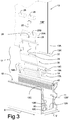
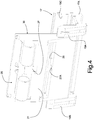
- the cradle 17 comprises, for example, a rest body 17A (made for example of plastic, such as POM), onto which the bottom 18 is defined for the face 13A' of the edge area 13A of the panel, and from which two opposite flank extend, a first flank 19A-19B (shown in Figs. 3 and 4 ) and a second flank 19C, for containing the edge 13A of the panel.
- a rest body 17A made for example of plastic, such as POM
- POM plastic
- the first flank has discontinuous surfaces of contact with the panel 13, and comprises at least two portions 19A and 19B projecting upwards and longitudinally spaced from each other to define a side space, where the flank side element 30 is arranged.
- the cradle 17 is made in two pieces, i.e. the rest body 17A and the flank side element 30, to the advantage of easiness of installation and of support capability of blocking the panel.
- the cradle may be made in a single piece, or in more than two pieces.
- the height h1, in the direction from the underside 12A to the opening 14 of the seat 12 (vertical direction in the figures), of the second flank 19C is lower than the height h2 of the flank side element 30; more preferably the height h1 is lower than half the height h2.
- the blocking device 16 comprises a side blocking unit 20 for blocking the panel 13, which is interposed between the flank side element 30 and the first side 12B' of the seat 12.
- the blocking unit is associated with the first side 12B' and not with the second side, i.e. the side blocking unit is interposed only between the flank side element 30 and the first side 12B' of the seat housing the panel, whilst at least one fixed abutment element 40 is provided between the opposite second side 12B" of the seat and the panel, against which the second surface 13B" of the panel abuts, so that the panel is blocked with the two surfaces 13B thereof respectively in contact with the flank side element 30 on one hand and, on the other hand, with the abutment element 40 and the flank 19C of the cradle 17.
- the abutment element 40 is a longitudinal gasket (made for example of TPE, such as a mixture of EVA and LDPE) fastened to the second side 12B" of the base 11.
- the gasket is fastened to a further element, for example a section bar, fastened to the base 11, at the upper part of the same base, in correspondence of, or close to, the second side 12B".
- the first side 12B' of the base preferably comprises a longitudinal rib 50 projecting towards the opposite second side 12B".
- the part of the flank side element 30 opposite to the surface of contact with the panel abuts against this longitudinal rib 50.
- the longitudinal rib 50 acts as a pivot for the flank side element 30.
- the first side 12B' of the seat 12 has a first flared portion 12E, to facilitate the right positioning of the set cradles 17/panel 13 in the seat.
- the cradle 17 has respective flared shapes for abutting on the first flared portion 12E of the seat 12, so as to optimize the respective positioning cradle-seat. Therefore, the first side 12B" has at least one segment, whose inclination is greater than that of any opposite second side 12B"; the seat is therefore more flared upwards in correspondence of the first side with respect to the second side.
- the distance, measured in correspondence of the opening 14 pf the seat 12, between the sides 12B' and 12B" and the respective surfaces of the panel 13 facing the sides is such that the distance between the first side 12B' and the panel is greater than that between the second side 12B" and the panel, as this latter distance in practice corresponds to the transverse width of the gasket 40.
- the seat 12 is therefore asymmetrical with respect to a longitudinal vertical plane passing through the centerline of the base, calculated with respect to the outside of the same base.
- the blocking unit 20 comprises a wedge-shaped element 21 (made for example of steel or aluminum), provided with a first face 21A and a second face 21B.
- the first face 21A abuts on the flank side element 30, so that the wedge-shaped element is slidable, in a sliding guide 22 defined on the outside of the flank side element 30 of the cradle 17, according to a direction from the underside 12A of the seat 12 towards the opening 14 and vice versa.
- the opposite second face 21B of the wedge-shaped element 21 is inclined relative to the sliding direction of the wedge-shaped element.
- the second face 21B is subdivided into two faces, as the wedge-shaped element 21 comprises a common segment 23, from which two wedge-shaped portions 24 extend, spaced from each other by a space 25.
- the blocking unit 20 comprises, in this example, two intermediate blocking elements 26 adapted to be arranged between the inclined second faces 21B (related to the two wedge-shaped portions 24) of the wedge-shaped element 21 and the undercut portion 15 provided on the first side 12B' of the housing seat 12.
- the intermediate blocking elements 26 are cylinders (made for example of plastic, for instance POM), whose radius substantially matches the radius of curvature of the undercut portion 15 (i.e. they have complementary shape).
- the blocking unit 20 further comprises an adjustment screw 27, screwed in a specifically threaded hole 28, provided through the wedge-shaped element 21, in this example in correspondence of the space 25.
- the screw 27 (made for example of steel) has an end 27A, adapted to abut against a portion 29 of the flank side element 30, and an opposite end, provided with a control head for a tool.
- the flank side element 30 may be made of metal, for example, steel, or in any other material, for example plastic of adequate hardness.
- the rotation of the screw in a first direction causes the wedge-shaped element 21 to slide towards the opening 14 of the housing seat 12 of the panel 13, so that the intermediate blocking elements 26 (the cylinders) push against respective undercut portions 15 of the first side 12B' of the seat 12, and thus the flank side element 30 pushes the surface of the panel, pushing this latter towards the second side 12B", and blocking it against the gasket 40.
- the rotation of the screw in opposite direction causes the wedge-shaped element 21 to slide in opposite direction towards the underside 12A of the seat 12, thus releasing it.
- the panel is inserted into the seat and abuts against the gasket 40 in the final vertical position.
- the panel is blocked, without the need for acting on the opposite side.
- the support 10 also comprises a device 60 for longitudinal closing the portion of the opening 14 of the base 11 defined on the side of the first side 12B' when the panel 13 is inserted into the base.
- the longitudinal closing device 60 comprises, for example, a longitudinal gasket 61 adapted to come into contact with the panel 13.
- the longitudinal closing device 60 comprises, for example, a longitudinal section bar 62 coupled to the end 12C of the first side 12B', and the longitudinal gasket is fastened to this section bar.
- Figs. 5 to 9 show a further embodiments of the support of the invention, which is a variant of the embodiments illustrated above.
- this variant provides for a transverse displacement apparatus 70 for transversally displacing the edge area 13A of the panel, thus changing the vertical inclination of the panel 13 and allowing therefor to adjust the panel inclination.
- transverse or “transversally” preferably refers to a transverse direction Y orthogonal to the direction of extension of the base 11 (i.e. of the seat 12), indicated with X in Fig. 3 , i.e. the direction from the side 12B' of the seat 12 to the opposite side 12B".
- the transverse displacement apparatus 70 is integrated in the cradle 17 and comprises a movable body 71 interposed between the second surface 13B" of the panel 13 and the portion of the cradle 17 opposite to the flank side element, i.e. the second flank 19C of the rest body 17A of the cradle.
- the movable body 71 is adapted to take more positions or configurations in the cradle, to each of which corresponds a different distance between the edge area 13A of the panel and the second side 12B" of the seat 12 (and therefore a different distance from the first side 12B', as the distance 12B'-12B" is fixed), as shown in Figs. 7 and 8 .
- the movable body 71 has preferably variable thickness; more specifically, in this example it is of the wedge-type, i.e. it has two opposite operating faces 72 and 73 inclined relative to each other, wherein the first operating face 72 is in contact with the second surface 13B" of the panel, and the opposite second operating face 73 moves along the second flank 19C of the rest body 17A of the cradle 17.
- the interface surface of mutual sliding between the second flank 19C of the rest body 17A and the movable body 71 is inclined and preferably shaped in zigzag fashion, as detailed below, with respect to the direction X of longitudinal extension, so that the movable body 71 moves along this inclined interface surface, changing the transverse position (i.e. the position along Y) thereof in the cradle, i.e. it moves away from, or towards, the sides 12B', 12B" of the seat 12, as shown in Figs. 7 and 8 .
- the movable body 17 is a wedge-shaped body with the first operating face 72 into contact with the second surface 13B" of the panel, and it remains alway parallel to itself during the motion along the second flank 19C of the rest body 17A of the cradle 17.
- the movable body shows alone in Fig. 7 , has a first part 71A that forms the wedge-shaped portion provided with the two operating faces 72 and 73, and that is therefore arranged between the second surface 13B" of the panel and the second flank 19C of the rest body 17A of the cradle 17, and a second part 71B, such as a flat tab, that is arranged in a lane 75, provided on the bottom 18, extending for example in a direction parallel to the direction of mutual sliding between the second flank 19C and the movable body 71.
- the face 13A' of the edge 13A rests on the bottom 18, above the lane 75, essentially so that the panel does not touch the second part 71B of the movable body.
- the wedge-shaped movable body 71 can be seen as a slider guided by the lane 75 and adapted to wedge itself between the panel and the flank of the cradle, with a displacement of the panel (in correspondence of the edge area).
- the movable body 71 is kinematically connected to an element for controlling the movement thereof.
- the movable body 71 comprises for example a rack-like portion 77, for example defined on the longitudinal edge of the flat tab defining the second part 71B of the movable body 71; a pinion 78, pivoted on the cradle (with vertical rotation axis, with reference to the drawing), is coupled to this rack-like portion 77 and acts as control element for controlling the movement of the movable body.
- the pinion 78 can be actuated (i.e. rotated) through a tool U that can be inserted into the seat 12 from the base 11 through the opening 14 (the tool head, for example a hexagonal head, enters a corresponding profile on the pinion).
- Fig. 8a shows the movable body 17 in a first position, corresponding to the position of the lower edge 13A' of the panel closer to the second flank 19C (distance d1).
- FIG. 8b shows the movable body translated in opposite direction (through the rotation of the pinion 78 on the rack 77), in a second position, corresponding to the position of the lower edge 13A' of the panel farther from the second flank 19C (distance d2, where d2>d1).
- Fig. 9a shows the movable body in a third position, intermediate between the two position described above, corresponding to the vertical position of the panel.
- Fig. 9b shows the inclined panel when the movable body 17 is in the second position (where the angular displacement with respect to the vertical position is indicated by the angle ⁇ );
- Fig. 9c shows the inclined panel when the movable body 17 is in the second position (where the angular displacement with respect to the vertical position is indicated by the angle ⁇ ).
- the second flank 19C of the rest body 17A has a zigzag or wavy profile 79.
- the coupling force due to the profile 79 is won by the push of the pinion on the rack during the adjustment step.
Landscapes
- Engineering & Computer Science (AREA)
- Architecture (AREA)
- Civil Engineering (AREA)
- Structural Engineering (AREA)
- Specific Sealing Or Ventilating Devices For Doors And Windows (AREA)
- Connection Of Plates (AREA)
- Pallets (AREA)
- Road Signs Or Road Markings (AREA)
Abstract
Description
- The present inventions relates to equipment for fastening, and supporting, structural or complementary panels in building industry, such as glazed frames, parapets, separating elements, etc.
- More in particular, the invention relates to a support for a panel, especially, even if not exclusively, for a glazed panel, for walls, separating walls, parapets, etc.
- Currently, different types of supports are used for supporting glazed panels.
- A type of support provides for a base, defining an open seat where the edge area of the panel is housed, and for a device, interposed between the panel and the base, for blocking the panel, or adjusting the inclination thereof, with respect to the base. An example of support is disclosed in the patent application no.
WO2019162825 , of the same Applicant. - The disclosed support is particularly innovative and is greatly appreciated by the market; however, as other known supports, it requires adjustments at both sides of the panel.
- This can be particularly uncomfortable in all cases where the adjustment shall be made on a particularly exposed side, as protective measures shall be adopted to operate on the side to be adjusted.
- The object of the invention is to overcome the drawbacks of the prior art supports for panels.
- In particular, an important object of the invention is to provide a support for a panel, especially, although not exclusively, for a glazed panel, allowing easy installation and adjustment of the panel by acting on only one side of the system.
- A further important object of the invention is to provide a support for a panel, especially, although not exclusively, for a glazed panel, allowing the panel to be easily blocked.
- A further important object of the invention is to provide a support for a panel, especially, although not exclusively, for a glazed panel, allowing to block the panel in a stable and durable way.
- These and other objects, that will be better described below, are achieved through a support for a panel comprising:
- a support base defining a seat for housing the edge area of the panel, the seat having a underside, two opposite sides extending from the underside, and an opening for inserting the panel into the seat, the opening being provided at the ends of the sides, a first side comprising a respective undercut portion with respect to its own end,
- at least one blocking device for blocking the panel to the support base, the device being interposed between the panel and the support base, and comprising
- a concave cradle for housing the end of the edge of the panel, the cradle comprising
- ∘ a bottom,
- ∘ a flank side element adapted to come into contact with a first surface of the panel on the side of the first side of the seat,
- a panel side blocking unit interposed between the flank side element and the first side of the seat, the blocking unit comprising
- ∘ at least one wedge-shaped element slidable on the outside of the flank element of the cradle from the underside of the seat towards the opening thereof and vice versa, the wedge-shaped element having a first abutment face on the outside of the flank side element of the cradle and an opposite second face, inclined with respect to the sliding direction of the wedge-shaped element,
- ∘ at least one intermediate blocking element adapted to be arranged between the opposite second face of the wedge-shaped element and the undercut portion provided on the first side of the housing seat,
- ∘ an adjustment screw screwed in a specifically threaded hole provided through the wedge-shaped element, the screw having an end adapted to abut against a portion of the cradle and an opposite end provided with a control head for a tool, so that a rotation of the screw in a first direction causes the wedge-shaped element to slide towards the opening of the panel housing seat, pushing the intermediate blocking element against the undercut portion of the first side of the seat, while a rotation of the screw in opposite direction causes the wedge-shaped element to slide in the opposite direction towards the underside of the seat,
- a concave cradle for housing the end of the edge of the panel, the cradle comprising
- According to preferred embodiment, the flank side element of the cradle is made as a separate and distinct piece with respect to the bottom; preferably, the cradle comprises a rest body, on which the bottom for the edge of the panel is defined; Preferably, at least one flank of the cradle, opposite to the flank side element, extends from the bottom; preferably the flank of the cradle opposite the flank side element is less high, from the underside of the seat towards the opening thereof, than the flank side element, and more preferably it is high less than half the height of the flank side element.
- Preferably, a first flank and a second flank, for containing the edge of the panel, extend opposite each other from the bottom. The first flank preferably comprises two portions projecting upwards and longitudinally spaced from each other to define a side space, where the flank side element is arranged; the first flank preferably has discontinuous surfaces of contact with the panel.
- According to preferred embodiments, the first side of the base comprises a longitudinal rib projecting towards the opposite side, against which the flank side element abuts.
- Preferably, the first flank abuts against the longitudinal rib.
- According to preferred embodiments, the at least one abutment element comprises a longitudinal gasket fixed to the second side of the base or to an additional element fixed on the base in correspondence of, or in proximity to, this second side. In other embodiments, the at least one abutment element may comprise parts directly defined on the second side of the base, and may be not necessarily a gasket (for example, it may be defined by a portion of the same base).
- According to preferred embodiments, the support comprises a device for longitudinal closing the portion of the opening of the said base defined on the side of the first side when the panel is inserted into the base; the longitudinal closing device preferably comprises a longitudinal gasket adapted to come into contact with the panel; wherein the longitudinal closing device preferably comprises a longitudinal section bar coupled to the end of the first side, this longitudinal gasket adapted to come into contact with the panel being fastened to the section bar.
- According to preferred embodiments, the flank side element defines a sliding guide for the at least one wedge-shaped element.
- According to preferred embodiments, the wedge-shaped element comprises two wedge-shaped portions spaced from each other, and the hole for the adjustment screw is provided in the space between the two wedge-shaped portions, two intermediate blocking elements being provided, each of which is adapted to interact with a respective wedge-shaped portion.
- According to preferred embodiments, the at least one intermediate blocking element is cylindrical in shape.
- According to preferred embodiments, the undercut portion of the first side of the seat has a curved shape, with preferably constant radius; the at least one intermediate blocking element has preferably an abutment surface for the undercut portion, whose shape is substantially complementary to that of the undercut portion.
- According to preferred embodiments, the first side comprising the undercut portion has a segment inclined from the inside towards the outside of the seat, making reference to the direction from the seat underside to the opening, the segment being connected to the undercut.
- According to preferred embodiments, when the glass is inserted in the seat, the distance, measured again in correspondence of the seat opening, between the sides and the respective surfaces facing the sides of the panel is such that the distance between the first side and the panel is greater than that between the second side and the panel.
- The seat is preferably asymmetrical with respect to a longitudinal vertical plane passing through the centerline of the base, calculated with respect to the outside of the base.
- According to preferred embodiments, the first side has at least one segment whose inclination is greater than that of any opposite second side; the seat is therefore more flared upwards in correspondence of the first side with respect to the second side.
- According to preferred embodiments, the support comprises an apparatus for transversally displacing the edge area of the panel, this resulting in a change in the vertical inclination of the same panel.
- The displacement apparatus preferably comprises at least a movable body interposed between the second surface of the panel and the cradle portion opposite the flank side element, the movable body being adapted to take more positions or configurations, to each of which corresponds a different distance between the edge area of the panel and the second side.
- The movable body is kinematically connected to an element for controlling the movement thereof, which can be preferably actuated through a tool that is preferably inserted in the seat of the base through the opening.
- The movable body has preferably variable thickness, more preferably it is of the wedge-type, i.e. it has two opposite operating faces inclined relative to each other, wherein the first operating face of the wedge-shaped movable body is in contact with the second surface of the panel, and the opposite second operating face moves on the cradle portion opposite the flank side element.
- The interface surface of mutual sliding between the cradle portion opposite the flank side element and the movable body is preferably inclined with respect to the direction of longitudinal extension of the housing seat of the panel, so that the movable body, moving along the inclined interface surface, changes its transverse position inside the seat, therefore inside the cradle, i.e. it moves away from, or towards, the sides of the seat; The movable body is preferably of the wedge-type, with an operating face always parallel to, and in contact with, the second surface of the panel.
- The movable body preferably comprises at least a rack-like portion, a pinion being provided, coupled to the rack that acts as control element for moving the movable body; the pinion is preferably pivoted on the cradle and can be rotated by means of a tool.
- The movable body has preferably a first part, adapted to be arranged between the second surface of the panel and the cradle portion opposite the flank side element, and a second part, adapted to be arranged in a lane provided in the bottom of the cradle; the rack-like portion is preferably provided on this second part; the cradle portion opposite the flank side element has preferably a zig-zag profile and the facing operating face of the movable body has a corresponding shape complementary to this profile, to reduce the risk of accidental sliding between movable body and cradle when the pinion is not actuated and/or when the wedge-shaped element exerts the fastening action on the panel.
- The movable body is preferably adapted to move along the at least one side of the cradle opposite the flank side element.
- The invention will be better understood by following the description below and the attached drawing, showing a non-limiting embodiment of the invention. More specifically, in the drawing:
-
Fig. 1 is a transverse view of the support of the invention, during the panel blocking step, cut-away in correspondence of the adjustment screw; -
Fig. 2 is a transverse view of the support of the invention, during the panel blocking step, cut-away in correspondence of the cylindrical intermediate blocking element; -
Fig. 3 is an exploded axonometric view of the support of the previous figures; -
Fig. 4 is an axonometric view of part of the components of the device for blocking the panel to the base according to the support of the previous figures; -
Fig. 5 is an axonometric view of a variant of the panel blocking device of the previous figures, for being integrated in a system allowing to adjust the panel inclination; -
Fig. 6 is a front view of the support of the invention, with the blocking device of -
Fig. 5 ; -
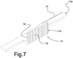
Fig. 7 shows a component of the blocking device ofFig. 5 ; -
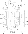
figs. 8a and 8b are views from the top of the blocking device ofFig. 5 , with the component ofFig. 7 in two different positions; -
Figs. 9a, 9b and 9c show three example of the support ofFig. 5 , with the panel inclined in three different manner according to the movement of the component ofFig. 7 . - With reference to the above cited figures, a support for a panel according to the invention is indicated as a whole with the
reference number 10. - The
support 10 comprises asupport base 11, for example realized by a section bar (for instance made of aluminum or steel) provided with abase face 11A to be arranged on, and to be stably fastened to, a horizontal or almost horizontal surface, wherein in the section bar a channel open at the top is provided, defining aseat 12 open at the top for inserting theedge area 13A of apanel 13, for instance a glazed panel, to be installed vertically or almost vertically. The panel defines twoopposite surfaces 13B' and 13B". - In other embodiments, the
support base 11 may be used as vertical support, for example fastening the base 11 with thebase face 11A very close to a wall, or even with a side face (i.e. the outer face of the base 11 orthogonal to thebase face 11A) very close to the wall or to a jamb. Analogously, thesupport base 11 may be used as an inclined support for thepanel 13. - The
seat 12 has aunderside 12A and two opposite sides, afirst side 12B' and a secondopposite side 12B" respectively, extending longitudinally, i.e. according to the extension of the base/section bar, from theunderside 12A. - The
reference number 14 indicates the opening, provided at the ends of thesides 12B' and 12B", for inserting the panel in theseat 12. - The
first side 12B' comprises, near theend 12C thereof, an undercut portion 15 (undercut with respect to the side thickness, i.e. a recess in the side thickness). - In this example, the undercut
portion 15 has a concave curved shape, and more precisely a shape with mainly constant radius, i.e. with a cross-section mainly shaped like an arc of a circle. Asegment 12D is provided, which is inclined from the inside towards the outside of theseat 12, with reference from theunderside 12A to theopening 14 of the seat, and is connected to the undercutportion 15. - The
support 10 further comprises at least oneblocking device 16 for blocking thepanel 13 to thesupport base 11. One ormore blocking devices 16 may be provided along thefirst side 12B', depending upon the length of the panel to be blocked (only one device 16t is shown in the figures). - The blocking
device 16 is interposed between thepanel 13 and thesupport base 11, and comprises aconcave cradle 17 for housing theedge area 13A of thepanel 13. The cradle comprises a bottom 18 and a flank side element 30 (made for example of plastic, such as POM) adapted to come into contact, with theportion 30A thereof, with afirst surface 13B' of the panel, at the side of thefirst side 12B' of theseat 12. - The
cradle 17 comprises, for example, arest body 17A (made for example of plastic, such as POM), onto which the bottom 18 is defined for theface 13A' of theedge area 13A of the panel, and from which two opposite flank extend, afirst flank 19A-19B (shown inFigs. 3 and4 ) and asecond flank 19C, for containing theedge 13A of the panel. - In this example, the first flank has discontinuous surfaces of contact with the
panel 13, and comprises at least twoportions flank side element 30 is arranged. - In practice, in this example, the
cradle 17 is made in two pieces, i.e. therest body 17A and theflank side element 30, to the advantage of easiness of installation and of support capability of blocking the panel. In other embodiments, the cradle may be made in a single piece, or in more than two pieces. - Adequately, the height h1, in the direction from the
underside 12A to theopening 14 of the seat 12 (vertical direction in the figures), of thesecond flank 19C is lower than the height h2 of theflank side element 30; more preferably the height h1 is lower than half the height h2. - The blocking
device 16 comprises aside blocking unit 20 for blocking thepanel 13, which is interposed between theflank side element 30 and thefirst side 12B' of theseat 12. The blocking unit is associated with thefirst side 12B' and not with the second side, i.e. the side blocking unit is interposed only between theflank side element 30 and thefirst side 12B' of the seat housing the panel, whilst at least one fixedabutment element 40 is provided between the oppositesecond side 12B" of the seat and the panel, against which thesecond surface 13B" of the panel abuts, so that the panel is blocked with the twosurfaces 13B thereof respectively in contact with theflank side element 30 on one hand and, on the other hand, with theabutment element 40 and theflank 19C of thecradle 17. - For example, the
abutment element 40 is a longitudinal gasket (made for example of TPE, such as a mixture of EVA and LDPE) fastened to thesecond side 12B" of thebase 11. In other embodiments, the gasket is fastened to a further element, for example a section bar, fastened to thebase 11, at the upper part of the same base, in correspondence of, or close to, thesecond side 12B". - The
first side 12B' of the base preferably comprises alongitudinal rib 50 projecting towards the oppositesecond side 12B". The part of theflank side element 30 opposite to the surface of contact with the panel abuts against thislongitudinal rib 50. During the blocking step, thelongitudinal rib 50 acts as a pivot for theflank side element 30. - In correspondence of the
underside 12A, thefirst side 12B' of theseat 12 has a first flaredportion 12E, to facilitate the right positioning of the set cradles 17/panel 13 in the seat. Adequately, in correspondence of the projectingportions cradle 17 has respective flared shapes for abutting on the first flaredportion 12E of theseat 12, so as to optimize the respective positioning cradle-seat. Therefore, thefirst side 12B" has at least one segment, whose inclination is greater than that of any oppositesecond side 12B"; the seat is therefore more flared upwards in correspondence of the first side with respect to the second side. - It should be therefore noted that in this example, when the glass is inserted in the seat, the distance, measured in correspondence of the
opening 14 pf theseat 12, between thesides 12B' and 12B" and the respective surfaces of thepanel 13 facing the sides is such that the distance between thefirst side 12B' and the panel is greater than that between thesecond side 12B" and the panel, as this latter distance in practice corresponds to the transverse width of thegasket 40. - The
seat 12 is therefore asymmetrical with respect to a longitudinal vertical plane passing through the centerline of the base, calculated with respect to the outside of the same base. - The blocking
unit 20 comprises a wedge-shaped element 21 (made for example of steel or aluminum), provided with afirst face 21A and asecond face 21B. Thefirst face 21A abuts on theflank side element 30, so that the wedge-shaped element is slidable, in a slidingguide 22 defined on the outside of theflank side element 30 of thecradle 17, according to a direction from theunderside 12A of theseat 12 towards theopening 14 and vice versa. The oppositesecond face 21B of the wedge-shapedelement 21 is inclined relative to the sliding direction of the wedge-shaped element. In this example, thesecond face 21B is subdivided into two faces, as the wedge-shapedelement 21 comprises a common segment 23, from which two wedge-shaped portions 24 extend, spaced from each other by a space 25. - The blocking
unit 20 comprises, in this example, twointermediate blocking elements 26 adapted to be arranged between the inclined second faces 21B (related to the two wedge-shaped portions 24) of the wedge-shapedelement 21 and the undercutportion 15 provided on thefirst side 12B' of thehousing seat 12. - In this example, the
intermediate blocking elements 26 are cylinders (made for example of plastic, for instance POM), whose radius substantially matches the radius of curvature of the undercut portion 15 (i.e. they have complementary shape). - The blocking
unit 20 further comprises anadjustment screw 27, screwed in a specifically threadedhole 28, provided through the wedge-shapedelement 21, in this example in correspondence of the space 25. - The screw 27 (made for example of steel) has an
end 27A, adapted to abut against aportion 29 of theflank side element 30, and an opposite end, provided with a control head for a tool. - The
flank side element 30 may be made of metal, for example, steel, or in any other material, for example plastic of adequate hardness. - The rotation of the screw in a first direction causes the wedge-shaped
element 21 to slide towards the opening 14 of thehousing seat 12 of thepanel 13, so that the intermediate blocking elements 26 (the cylinders) push against respective undercutportions 15 of thefirst side 12B' of theseat 12, and thus theflank side element 30 pushes the surface of the panel, pushing this latter towards thesecond side 12B", and blocking it against thegasket 40. The rotation of the screw in opposite direction causes the wedge-shapedelement 21 to slide in opposite direction towards theunderside 12A of theseat 12, thus releasing it. - During installation, the panel is inserted into the seat and abuts against the
gasket 40 in the final vertical position. By acting only on the blocking units on the first side of the seat of the section bar, the panel is blocked, without the need for acting on the opposite side. - The
support 10 also comprises adevice 60 for longitudinal closing the portion of theopening 14 of the base 11 defined on the side of thefirst side 12B' when thepanel 13 is inserted into the base. - The
longitudinal closing device 60 comprises, for example, alongitudinal gasket 61 adapted to come into contact with thepanel 13. - The
longitudinal closing device 60 comprises, for example, alongitudinal section bar 62 coupled to theend 12C of thefirst side 12B', and the longitudinal gasket is fastened to this section bar. -
Figs. 5 to 9 show a further embodiments of the support of the invention, which is a variant of the embodiments illustrated above. - In particular, this variant provides for a
transverse displacement apparatus 70 for transversally displacing theedge area 13A of the panel, thus changing the vertical inclination of thepanel 13 and allowing therefor to adjust the panel inclination. - The term "transverse" or "transversally" preferably refers to a transverse direction Y orthogonal to the direction of extension of the base 11 (i.e. of the seat 12), indicated with X in
Fig. 3 , i.e. the direction from theside 12B' of theseat 12 to theopposite side 12B". - In this example, the
transverse displacement apparatus 70 is integrated in thecradle 17 and comprises amovable body 71 interposed between thesecond surface 13B" of thepanel 13 and the portion of thecradle 17 opposite to the flank side element, i.e. thesecond flank 19C of therest body 17A of the cradle. - The
movable body 71 is adapted to take more positions or configurations in the cradle, to each of which corresponds a different distance between theedge area 13A of the panel and thesecond side 12B" of the seat 12 (and therefore a different distance from thefirst side 12B', as thedistance 12B'-12B" is fixed), as shown inFigs. 7 and8 . - The
movable body 71 has preferably variable thickness; more specifically, in this example it is of the wedge-type, i.e. it has two opposite operating faces 72 and 73 inclined relative to each other, wherein thefirst operating face 72 is in contact with thesecond surface 13B" of the panel, and the oppositesecond operating face 73 moves along thesecond flank 19C of therest body 17A of thecradle 17. - The interface surface of mutual sliding between the
second flank 19C of therest body 17A and the movable body 71 (i.e. thesecond operating face 73 thereof) is inclined and preferably shaped in zigzag fashion, as detailed below, with respect to the direction X of longitudinal extension, so that themovable body 71 moves along this inclined interface surface, changing the transverse position (i.e. the position along Y) thereof in the cradle, i.e. it moves away from, or towards, thesides 12B', 12B" of theseat 12, as shown inFigs. 7 and8 . It should be noted that, in this example, themovable body 17 is a wedge-shaped body with thefirst operating face 72 into contact with thesecond surface 13B" of the panel, and it remains alway parallel to itself during the motion along thesecond flank 19C of therest body 17A of thecradle 17. - In this example, the movable body, shows alone in
Fig. 7 , has afirst part 71A that forms the wedge-shaped portion provided with the two operating faces 72 and 73, and that is therefore arranged between thesecond surface 13B" of the panel and thesecond flank 19C of therest body 17A of thecradle 17, and asecond part 71B, such as a flat tab, that is arranged in alane 75, provided on the bottom 18, extending for example in a direction parallel to the direction of mutual sliding between thesecond flank 19C and themovable body 71. Theface 13A' of theedge 13A rests on the bottom 18, above thelane 75, essentially so that the panel does not touch thesecond part 71B of the movable body. In practice, the wedge-shapedmovable body 71 can be seen as a slider guided by thelane 75 and adapted to wedge itself between the panel and the flank of the cradle, with a displacement of the panel (in correspondence of the edge area). - Adequately, the
movable body 71 is kinematically connected to an element for controlling the movement thereof. In this regard, themovable body 71 comprises for example a rack-like portion 77, for example defined on the longitudinal edge of the flat tab defining thesecond part 71B of themovable body 71; apinion 78, pivoted on the cradle (with vertical rotation axis, with reference to the drawing), is coupled to this rack-like portion 77 and acts as control element for controlling the movement of the movable body. Adequately, thepinion 78 can be actuated (i.e. rotated) through a tool U that can be inserted into theseat 12 from the base 11 through the opening 14 (the tool head, for example a hexagonal head, enters a corresponding profile on the pinion). - To adjust the inclination of the panel through the
transverse displacement apparatus 70, it is necessary to loosen the blockingdevice 16 and then to act with the tool U on the pinion, which translates themovable body 71 along thesecond flank 19C of therest body 17A of thecradle 17, thus pushing and moving the panel in transverse direction.Fig. 8a shows themovable body 17 in a first position, corresponding to the position of thelower edge 13A' of the panel closer to thesecond flank 19C (distance d1).Fig. 8b shows the movable body translated in opposite direction (through the rotation of thepinion 78 on the rack 77), in a second position, corresponding to the position of thelower edge 13A' of the panel farther from thesecond flank 19C (distance d2, where d2>d1). Different inclination of the panel with respect to the vertical correspond to these two positions. For example,Fig. 9a shows the movable body in a third position, intermediate between the two position described above, corresponding to the vertical position of the panel.Fig. 9b shows the inclined panel when themovable body 17 is in the second position (where the angular displacement with respect to the vertical position is indicated by the angle α);Fig. 9c shows the inclined panel when themovable body 17 is in the second position (where the angular displacement with respect to the vertical position is indicated by the angle β). - To prevent the
movable body 17 from accidentally moving when it has achieved the desired position, thesecond flank 19C of therest body 17A has a zigzag or wavy profile 79. On the facingsecond operating face 73 of themovable body 71 there is defined a corresponding matching i.e. complementary profile, thus reducing the risk of accidental mutual sliding and/or of sliding due to the pressure of the blockingdevice 16. Obviously, the coupling force due to the profile 79 is won by the push of the pinion on the rack during the adjustment step. - It is understood that what is illustrated purely represents possible non-limiting embodiments of the invention, which may vary in forms and arrangements without departing from the scope of the concept, on which the invention is based. Any reference numerals in the appended claims are provided for the sole purpose of facilitating the reading thereof in the light of the description above and the accompanying drawings and do not in any way limit the scope of protection.
Claims (21)
- A support for a panel comprising:- a support base defining a seat for housing the edge area of the panel, said seat having a underside, two opposite sides extending from said underside, and an opening for inserting the panel into the seat, the opening being provided at the ends of said sides, a first side comprising a respective undercut portion with respect to its own end,- at least one blocking device for blocking the panel to said support base, the device being interposed between the panel and said support base, and comprisingcharacterized in that said panel side blocking unit is interposed only between said flank side element and said first side of the panel housing seat, wherein between the second opposite side of said seat and said panel at least one abutment element is provided, against which the second surface of the panel abuts, so that said panel is blocked with its two surfaces in contact with said flank side element on one side, and said at least one fixed abutment element on the other side respectively.∘ a concave cradle for housing the end of the edge of the panel, said cradle comprising▪ a bottom,▪ a flank side element adapted to come into contact with a first surface of said panel on the side of said first side of said seat,∘ a panel side blocking unit interposed between said flank side element and said first side of said seat, said blocking unit comprising▪ at least one wedge-shaped element slidable on the outside of said flank element of the cradle from the underside of said seat towards the opening thereof and vice versa, said wedge-shaped element having a first abutment face on the outside of said flank side element of the cradle and an opposite second face, inclined with respect to the sliding direction of the wedge-shaped element,▪ at least one intermediate blocking element adapted to be arranged between said opposite second face of the wedge-shaped element and said undercut portion provided on said first side of said housing seat,▪ an adjustment screw screwed in a specifically threaded hole provided through said wedge-shaped element, said screw having an end adapted to abut against a portion of said cradle and an opposite end provided with a control head for a tool, so that a rotation of said screw in a first direction causes said wedge-shaped element to slide towards said opening of the panel housing seat, pushing said intermediate blocking element against said undercut portion of said first side of said seat, while a rotation of said screw in opposite direction causes said wedge-shaped element to slide in the opposite direction towards the underside of the seat,
- The support for panel of claim 1, wherein said flank side element of said cradle is made as a separate and distinct piece with respect to said bottom.
- The support for panel of claim 2, wherein said cradle comprises a rest body, on which said bottom for the edge of the panel is defined, from which bottom at least one flank of said cradle extends, opposite to said flank side element; preferably the said at least one flank of said cradle opposite said flank side element has height, in the direction from the underside of said seat towards the opening thereof, lower than that of said flank side element, and more preferably the height of the flank is lower than half the height of said flank side element.
- The support for panel of claim 2 or 3, wherein at least a first flank and a second flank, opposite each other, extend from said bottom, for containing said edge of the panel.
- The support of claim 4, wherein said first flank comprises two portions projecting upwards and longitudinally spaced from each other to define a side space, where said flank side element is arranged.
- The support for panel of claim 5, wherein said first flank has discontinuous contact surfaces with said panel.
- The support for panel of one or more of the previous claims, wherein said first side of said base comprises a longitudinal rib projecting towards the opposite side, against which said flank side element abuts.
- The support for panel of claims 4, 5, or 6 and of claim 7, wherein said first flank abuts against said longitudinal rib.
- The support for panel of one or more of the previous claims, wherein said at least one abutment element comprises a longitudinal gasket fixed to the second side of said base, or to an additional element fixed on said base in correspondence of, or in proximity to, said second side.
- The support of one or more of the previous claims, comprising a device for longitudinal closing the portion of the opening of said base defined on the side of the first side when the panel is inserted into the base; preferably said longitudinal closing device comprises a longitudinal gasket adapted to come into contact with the panel; wherein the longitudinal closing device preferably comprises a longitudinal section bar coupled to the end of the first side, this longitudinal gasket adapted to come into contact with the panel being fastened to the section bar.
- The support for panel of one or more of the previous claims, wherein said flank side element defines a sliding guide for said at least one wedge-shaped element.
- The support for panel of one or more of the previous claims, wherein said wedge-shaped element comprises two wedge-shaped portions spaced from each other, and wherein in the space between said two wedge-shaped portions, said hole is provided for said adjustment screw, two intermediate blocking elements being provided, each of which is adapted to interact with a respective said wedge-shaped portion.
- The support for panel of one or more of the previous claims, wherein said at least one intermediate blocking element is cylindrical in shape.
- The support for panel of one or more of claims 2 to 12, comprising a transverse displacement apparatus for moving the edge area of the panel, thus changing the vertical inclination of the same panel.
- The support for panel of claim 14, wherein said displacement apparatus comprises at least a movable body interposed between said second surface of said panel and the cradle portion opposite said flank side element, said movable body being adapted to take more positions or configurations, to each of which corresponds a different distance between the edge area of the panel and the second side.
- The support for panel of claim 15, wherein said at least one movable body is kinematically connected to an element for controlling the movement thereof, which can be preferably actuated through a tool that is preferably inserted in the seat of the base through said opening.
- The support for panel of claim 15 or 16, wherein said movable body has preferably variable thickness, more preferably it is of the wedge-type, i.e. it has operating faces inclined relative to each other, wherein the first operating face of the wedge-shaped movable body is in contact with the second surface of the panel, and the opposite second operating face moves on said cradle portion opposite said flank side element.
- The support for panel of claim 15, 16, or 17, wherein the interface surface of mutual sliding between said cradle portion opposite said flank side element and said movable body is inclined with respect to the direction of longitudinal extension of said housing seat of the panel, so that said movable body, moving along said inclined interface surface, changes its position inside said seat, therefore inside said cradle, i.e. it moves away from, or towards, the sides of said seat; said movable body is preferably of the wedge-type, with an operating face always parallel to, and in contact with, the second surface of said panel.
- The support for panel of one or more of claims 15 to 18, wherein said movable body comprises at least a rack-like portion, a pinion being provided, coupled to said rack that acts as control element for moving said movable body; said pinion being preferably pivoted on said cradle and being rotatable by means of a tool.
- The support for panel of claim 19, wherein said movable body has preferably a first part, adapted to be arranged between said second surface of said panel and the cradle portion opposite said flank side element, and a second part, adapted to be arranged in a lane provided in the bottom of said cradle; said rack-like portion being preferably provided on said second part; said cradle portion opposite said flank side element having preferably a zigzag profile and the the facing operating face of the movable body having a corresponding shape complementary to this profile, to reduce the risk of accidental sliding between movable body and cradle when the pinion is not actuated.
- The support for panel of claim 3 and of one or more of claims 17 to 20, wherein said movable body is adapted to move along said at least one flank of said cradle, opposite said flank side element.
Applications Claiming Priority (1)
| Application Number | Priority Date | Filing Date | Title |
|---|---|---|---|
| IT102019000019988A IT201900019988A1 (en) | 2019-10-29 | 2019-10-29 | SUPPORT FOR PANEL WITH LATERAL LOCK |
Publications (3)
| Publication Number | Publication Date |
|---|---|
| EP3816362A1 true EP3816362A1 (en) | 2021-05-05 |
| EP3816362B1 EP3816362B1 (en) | 2024-09-11 |
| EP3816362C0 EP3816362C0 (en) | 2024-09-11 |
Family
ID=69743814
Family Applications (1)
| Application Number | Title | Priority Date | Filing Date |
|---|---|---|---|
| EP20204433.5A Active EP3816362B1 (en) | 2019-10-29 | 2020-10-28 | Support for panel with side blocking device |
Country Status (4)
| Country | Link |
|---|---|
| EP (1) | EP3816362B1 (en) |
| ES (1) | ES2999309T3 (en) |
| IT (1) | IT201900019988A1 (en) |
| PL (1) | PL3816362T3 (en) |
Cited By (5)
| Publication number | Priority date | Publication date | Assignee | Title |
|---|---|---|---|---|
| EP4273346A1 (en) * | 2022-05-02 | 2023-11-08 | Vladimir Lacko | Tilting sliding system |
| EP4296450A1 (en) * | 2022-06-24 | 2023-12-27 | Pure Vista Ltd | A system and method for adjusting the alignment of a flat panel |
| EP4424485A1 (en) | 2023-02-28 | 2024-09-04 | Saint-Gobain Glass France | Method for the off-site construction of a prefabricated construction element in concrete comprising a profile embedded therein |
| IT202300007215A1 (en) * | 2023-04-14 | 2024-10-14 | Mypro Res S R L | FIXING DEVICE FOR PANELS, ESPECIALLY FOR GLASS SHEETS |
| EP4726137A1 (en) | 2024-10-09 | 2026-04-15 | Logli Massimo S.P.A. | Improved panel support |
Citations (7)
| Publication number | Priority date | Publication date | Assignee | Title |
|---|---|---|---|---|
| US20160298375A1 (en) * | 2015-04-07 | 2016-10-13 | R & B Wagner, Inc. | Partition mounting system with clamp capture shoe |
| EP3121345A1 (en) * | 2015-07-22 | 2017-01-25 | Qingdao Jinfer International Trading Co., Ltd | Clamping system for mounting glass balustrade |
| DE202017105703U1 (en) * | 2017-09-20 | 2018-01-24 | Q-Railing Europe Gmbh & Co. Kg | System for aligning railing panels |
| WO2018047179A1 (en) * | 2016-09-11 | 2018-03-15 | Tomak Ltd. | System and method for plate alignment |
| EP3372748A1 (en) * | 2017-03-07 | 2018-09-12 | Logli Massimo S.P.A. | Panel support apparatus |
| DE102017125020A1 (en) * | 2017-10-25 | 2019-04-25 | Rupert Weiss | Holding device for fixing a balustrade or railing plate |
| WO2019162825A1 (en) | 2018-02-20 | 2019-08-29 | Logli Massimo S.P.A. | Panel support |
-
2019
- 2019-10-29 IT IT102019000019988A patent/IT201900019988A1/en unknown
-
2020
- 2020-10-28 PL PL20204433.5T patent/PL3816362T3/en unknown
- 2020-10-28 ES ES20204433T patent/ES2999309T3/en active Active
- 2020-10-28 EP EP20204433.5A patent/EP3816362B1/en active Active
Patent Citations (7)
| Publication number | Priority date | Publication date | Assignee | Title |
|---|---|---|---|---|
| US20160298375A1 (en) * | 2015-04-07 | 2016-10-13 | R & B Wagner, Inc. | Partition mounting system with clamp capture shoe |
| EP3121345A1 (en) * | 2015-07-22 | 2017-01-25 | Qingdao Jinfer International Trading Co., Ltd | Clamping system for mounting glass balustrade |
| WO2018047179A1 (en) * | 2016-09-11 | 2018-03-15 | Tomak Ltd. | System and method for plate alignment |
| EP3372748A1 (en) * | 2017-03-07 | 2018-09-12 | Logli Massimo S.P.A. | Panel support apparatus |
| DE202017105703U1 (en) * | 2017-09-20 | 2018-01-24 | Q-Railing Europe Gmbh & Co. Kg | System for aligning railing panels |
| DE102017125020A1 (en) * | 2017-10-25 | 2019-04-25 | Rupert Weiss | Holding device for fixing a balustrade or railing plate |
| WO2019162825A1 (en) | 2018-02-20 | 2019-08-29 | Logli Massimo S.P.A. | Panel support |
Cited By (9)
| Publication number | Priority date | Publication date | Assignee | Title |
|---|---|---|---|---|
| EP4273346A1 (en) * | 2022-05-02 | 2023-11-08 | Vladimir Lacko | Tilting sliding system |
| EP4296450A1 (en) * | 2022-06-24 | 2023-12-27 | Pure Vista Ltd | A system and method for adjusting the alignment of a flat panel |
| EP4715137A3 (en) * | 2022-06-24 | 2026-06-24 | Pure Vista Ltd | A system and method for adjusting the alignment of a flat panel |
| US12668975B2 (en) | 2022-06-24 | 2026-06-30 | Pure Vista Ltd | System and method for adjusting the alignment of a flat panel |
| EP4424485A1 (en) | 2023-02-28 | 2024-09-04 | Saint-Gobain Glass France | Method for the off-site construction of a prefabricated construction element in concrete comprising a profile embedded therein |
| WO2024180046A1 (en) | 2023-02-28 | 2024-09-06 | Saint-Gobain Glass France | Method for the off-site construction of a prefabricated construction element in concrete comprising a profile embedded therein |
| IT202300007215A1 (en) * | 2023-04-14 | 2024-10-14 | Mypro Res S R L | FIXING DEVICE FOR PANELS, ESPECIALLY FOR GLASS SHEETS |
| WO2024213956A1 (en) * | 2023-04-14 | 2024-10-17 | Mypro Research S.R.L. | Fastening device for panels in particular for glass plates |
| EP4726137A1 (en) | 2024-10-09 | 2026-04-15 | Logli Massimo S.P.A. | Improved panel support |
Also Published As
| Publication number | Publication date |
|---|---|
| PL3816362T3 (en) | 2025-04-14 |
| EP3816362B1 (en) | 2024-09-11 |
| EP3816362C0 (en) | 2024-09-11 |
| IT201900019988A1 (en) | 2021-04-29 |
| ES2999309T3 (en) | 2025-02-25 |
Similar Documents
| Publication | Publication Date | Title |
|---|---|---|
| EP3816362B1 (en) | Support for panel with side blocking device | |
| EP2815040B1 (en) | Regulation and/or locking device for a plate | |
| JP5603585B2 (en) | Concealed door hinge | |
| EP0390045B1 (en) | Shelf-support bracket | |
| CN103291157B (en) | Door hinge for layout hidden between doorframe and door leaf | |
| US10253798B2 (en) | Device for attaching a guide unit to a furniture part | |
| US20020181809A1 (en) | Linear guide | |
| US20210172178A1 (en) | Leveling partition mounting system | |
| CN106401340B (en) | For hiding the door hinge being arranged between door leaf and doorframe | |
| US20090089974A1 (en) | Height adjustment device for a hinge | |
| US10683688B2 (en) | Folding device with adjusting strip | |
| US20180372154A1 (en) | Linear guide with self-adjusting play reduction | |
| US20220195734A1 (en) | Arrangement for securing a panel in a rail by tightening outer wedges from an inner side of the panel | |
| EP3762561B1 (en) | Panel support | |
| CA3030213A1 (en) | Adjustable idler support system for conveyor belt | |
| EP2047049B1 (en) | Hinge for a roof window with a pivot sash | |
| MXPA06006052A (en) | Mechanism for a sliding glass pane. | |
| EP2292881B1 (en) | Hinge | |
| EP2789780B1 (en) | Support and adjustment device of a trolley for sliding doors or panels | |
| DK2644812T3 (en) | GLASS SEATING SYSTEM OR LIKE | |
| SE462114B (en) | GOING TO DO DOORS, WINDOWS AND LIKE | |
| US20160297089A1 (en) | Apparatus for Cutting Elastic Coatings | |
| AU2021201543A1 (en) | Extendable curtain track assembly | |
| CN108699876A (en) | Lining plate arrangement with frame-side adjusting elements | |
| EP1842470A2 (en) | Shower box construction with an improved assembling |
Legal Events
| Date | Code | Title | Description |
|---|---|---|---|
| PUAI | Public reference made under article 153(3) epc to a published international application that has entered the european phase |
Free format text: ORIGINAL CODE: 0009012 |
|
| STAA | Information on the status of an ep patent application or granted ep patent |
Free format text: STATUS: THE APPLICATION HAS BEEN PUBLISHED |
|
| AK | Designated contracting states |
Kind code of ref document: A1 Designated state(s): AL AT BE BG CH CY CZ DE DK EE ES FI FR GB GR HR HU IE IS IT LI LT LU LV MC MK MT NL NO PL PT RO RS SE SI SK SM TR |
|
| STAA | Information on the status of an ep patent application or granted ep patent |
Free format text: STATUS: REQUEST FOR EXAMINATION WAS MADE |
|
| 17P | Request for examination filed |
Effective date: 20211029 |
|
| RBV | Designated contracting states (corrected) |
Designated state(s): AL AT BE BG CH CY CZ DE DK EE ES FI FR GB GR HR HU IE IS IT LI LT LU LV MC MK MT NL NO PL PT RO RS SE SI SK SM TR |
|
| GRAP | Despatch of communication of intention to grant a patent |
Free format text: ORIGINAL CODE: EPIDOSNIGR1 |
|
| STAA | Information on the status of an ep patent application or granted ep patent |
Free format text: STATUS: GRANT OF PATENT IS INTENDED |
|
| INTG | Intention to grant announced |
Effective date: 20240404 |
|
| GRAS | Grant fee paid |
Free format text: ORIGINAL CODE: EPIDOSNIGR3 |
|
| GRAA | (expected) grant |
Free format text: ORIGINAL CODE: 0009210 |
|
| STAA | Information on the status of an ep patent application or granted ep patent |
Free format text: STATUS: THE PATENT HAS BEEN GRANTED |
|
| AK | Designated contracting states |
Kind code of ref document: B1 Designated state(s): AL AT BE BG CH CY CZ DE DK EE ES FI FR GB GR HR HU IE IS IT LI LT LU LV MC MK MT NL NO PL PT RO RS SE SI SK SM TR |
|
| REG | Reference to a national code |
Ref country code: GB Ref legal event code: FG4D |
|
| REG | Reference to a national code |
Ref country code: CH Ref legal event code: EP |
|
| REG | Reference to a national code |
Ref country code: DE Ref legal event code: R096 Ref document number: 602020037449 Country of ref document: DE |
|
| REG | Reference to a national code |
Ref country code: IE Ref legal event code: FG4D |
|
| U01 | Request for unitary effect filed |
Effective date: 20240925 |
|
| U07 | Unitary effect registered |
Designated state(s): AT BE BG DE DK EE FI FR IT LT LU LV MT NL PT RO SE SI Effective date: 20241018 |
|
| U20 | Renewal fee for the european patent with unitary effect paid |
Year of fee payment: 5 Effective date: 20241028 |
|
| PG25 | Lapsed in a contracting state [announced via postgrant information from national office to epo] |
Ref country code: NO Free format text: LAPSE BECAUSE OF FAILURE TO SUBMIT A TRANSLATION OF THE DESCRIPTION OR TO PAY THE FEE WITHIN THE PRESCRIBED TIME-LIMIT Effective date: 20241211 |
|
| PG25 | Lapsed in a contracting state [announced via postgrant information from national office to epo] |
Ref country code: GR Free format text: LAPSE BECAUSE OF FAILURE TO SUBMIT A TRANSLATION OF THE DESCRIPTION OR TO PAY THE FEE WITHIN THE PRESCRIBED TIME-LIMIT Effective date: 20241212 |
|
| PG25 | Lapsed in a contracting state [announced via postgrant information from national office to epo] |
Ref country code: HR Free format text: LAPSE BECAUSE OF FAILURE TO SUBMIT A TRANSLATION OF THE DESCRIPTION OR TO PAY THE FEE WITHIN THE PRESCRIBED TIME-LIMIT Effective date: 20240911 |
|
| PG25 | Lapsed in a contracting state [announced via postgrant information from national office to epo] |
Ref country code: RS Free format text: LAPSE BECAUSE OF FAILURE TO SUBMIT A TRANSLATION OF THE DESCRIPTION OR TO PAY THE FEE WITHIN THE PRESCRIBED TIME-LIMIT Effective date: 20241211 |
|
| PG25 | Lapsed in a contracting state [announced via postgrant information from national office to epo] |
Ref country code: RS Free format text: LAPSE BECAUSE OF FAILURE TO SUBMIT A TRANSLATION OF THE DESCRIPTION OR TO PAY THE FEE WITHIN THE PRESCRIBED TIME-LIMIT Effective date: 20241211 Ref country code: NO Free format text: LAPSE BECAUSE OF FAILURE TO SUBMIT A TRANSLATION OF THE DESCRIPTION OR TO PAY THE FEE WITHIN THE PRESCRIBED TIME-LIMIT Effective date: 20241211 Ref country code: HR Free format text: LAPSE BECAUSE OF FAILURE TO SUBMIT A TRANSLATION OF THE DESCRIPTION OR TO PAY THE FEE WITHIN THE PRESCRIBED TIME-LIMIT Effective date: 20240911 Ref country code: GR Free format text: LAPSE BECAUSE OF FAILURE TO SUBMIT A TRANSLATION OF THE DESCRIPTION OR TO PAY THE FEE WITHIN THE PRESCRIBED TIME-LIMIT Effective date: 20241212 |
|
| REG | Reference to a national code |
Ref country code: ES Ref legal event code: FG2A Ref document number: 2999309 Country of ref document: ES Kind code of ref document: T3 Effective date: 20250225 |
|
| PG25 | Lapsed in a contracting state [announced via postgrant information from national office to epo] |
Ref country code: IS Free format text: LAPSE BECAUSE OF FAILURE TO SUBMIT A TRANSLATION OF THE DESCRIPTION OR TO PAY THE FEE WITHIN THE PRESCRIBED TIME-LIMIT Effective date: 20250111 |
|
| PG25 | Lapsed in a contracting state [announced via postgrant information from national office to epo] |
Ref country code: SM Free format text: LAPSE BECAUSE OF FAILURE TO SUBMIT A TRANSLATION OF THE DESCRIPTION OR TO PAY THE FEE WITHIN THE PRESCRIBED TIME-LIMIT Effective date: 20240911 |
|
| PG25 | Lapsed in a contracting state [announced via postgrant information from national office to epo] |
Ref country code: CZ Free format text: LAPSE BECAUSE OF FAILURE TO SUBMIT A TRANSLATION OF THE DESCRIPTION OR TO PAY THE FEE WITHIN THE PRESCRIBED TIME-LIMIT Effective date: 20240911 |
|
| PG25 | Lapsed in a contracting state [announced via postgrant information from national office to epo] |
Ref country code: SK Free format text: LAPSE BECAUSE OF FAILURE TO SUBMIT A TRANSLATION OF THE DESCRIPTION OR TO PAY THE FEE WITHIN THE PRESCRIBED TIME-LIMIT Effective date: 20240911 |
|
| REG | Reference to a national code |
Ref country code: CH Ref legal event code: PL |
|
| PG25 | Lapsed in a contracting state [announced via postgrant information from national office to epo] |
Ref country code: MC Free format text: LAPSE BECAUSE OF FAILURE TO SUBMIT A TRANSLATION OF THE DESCRIPTION OR TO PAY THE FEE WITHIN THE PRESCRIBED TIME-LIMIT Effective date: 20240911 |
|
| PLBE | No opposition filed within time limit |
Free format text: ORIGINAL CODE: 0009261 |
|
| STAA | Information on the status of an ep patent application or granted ep patent |
Free format text: STATUS: NO OPPOSITION FILED WITHIN TIME LIMIT |
|
| PG25 | Lapsed in a contracting state [announced via postgrant information from national office to epo] |
Ref country code: CH Free format text: LAPSE BECAUSE OF NON-PAYMENT OF DUE FEES Effective date: 20241031 |
|
| 26N | No opposition filed |
Effective date: 20250612 |
|
| GBPC | Gb: european patent ceased through non-payment of renewal fee |
Effective date: 20241211 |
|
| PGFP | Annual fee paid to national office [announced via postgrant information from national office to epo] |
Ref country code: PL Payment date: 20250930 Year of fee payment: 6 Ref country code: TR Payment date: 20250930 Year of fee payment: 6 |
|
| PG25 | Lapsed in a contracting state [announced via postgrant information from national office to epo] |
Ref country code: GB Free format text: LAPSE BECAUSE OF NON-PAYMENT OF DUE FEES Effective date: 20241211 |
|
| PG25 | Lapsed in a contracting state [announced via postgrant information from national office to epo] |
Ref country code: IE Free format text: LAPSE BECAUSE OF NON-PAYMENT OF DUE FEES Effective date: 20241028 |
|
| U20 | Renewal fee for the european patent with unitary effect paid |
Year of fee payment: 6 Effective date: 20251029 |
|
| PGFP | Annual fee paid to national office [announced via postgrant information from national office to epo] |
Ref country code: ES Payment date: 20251118 Year of fee payment: 6 |
|
| U1H | Name or address of the proprietor changed after the registration of the unitary effect |
Owner name: SAINT-GOBAIN LOGLI S.R.L.; IT |
|
| PG25 | Lapsed in a contracting state [announced via postgrant information from national office to epo] |
Ref country code: HU Free format text: LAPSE BECAUSE OF FAILURE TO SUBMIT A TRANSLATION OF THE DESCRIPTION OR TO PAY THE FEE WITHIN THE PRESCRIBED TIME-LIMIT; INVALID AB INITIO Effective date: 20201028 |
|
| PG25 | Lapsed in a contracting state [announced via postgrant information from national office to epo] |
Ref country code: CY Free format text: LAPSE BECAUSE OF FAILURE TO SUBMIT A TRANSLATION OF THE DESCRIPTION OR TO PAY THE FEE WITHIN THE PRESCRIBED TIME-LIMIT; INVALID AB INITIO Effective date: 20201028 |