EP3816337A1 - A dryer comprising a self-cleaning filter - Google Patents
A dryer comprising a self-cleaning filter Download PDFInfo
- Publication number
- EP3816337A1 EP3816337A1 EP20199421.7A EP20199421A EP3816337A1 EP 3816337 A1 EP3816337 A1 EP 3816337A1 EP 20199421 A EP20199421 A EP 20199421A EP 3816337 A1 EP3816337 A1 EP 3816337A1
- Authority
- EP
- European Patent Office
- Prior art keywords
- filter
- scraper
- dryer
- gear
- housing
- Prior art date
- Legal status (The legal status is an assumption and is not a legal conclusion. Google has not performed a legal analysis and makes no representation as to the accuracy of the status listed.)
- Granted
Links
Images


Classifications
-
- D—TEXTILES; PAPER
- D06—TREATMENT OF TEXTILES OR THE LIKE; LAUNDERING; FLEXIBLE MATERIALS NOT OTHERWISE PROVIDED FOR
- D06F—LAUNDERING, DRYING, IRONING, PRESSING OR FOLDING TEXTILE ARTICLES
- D06F58/00—Domestic laundry dryers
- D06F58/20—General details of domestic laundry dryers
- D06F58/22—Lint collecting arrangements
Definitions
- the present invention relates to a dryer comprising a self-cleaning filter.
- the use of mechanical scrapers for automatically cleaning the filters used in dryers is known in the art.
- the scraper collects fibers accumulated on the filter by contacting the filter.
- Various structural modifications has to be made in the dryer and the filter in order to allow the usage of such filters.
- the filter In the dryers having state of the art scrapers, the filter has only one filtering surface and is positioned in different angles/ways in order to allow the operation of the scraper.
- Some of the reasons of not using the filters available in the state of the art with scrapers are the sealing problem caused by the scraper in the circulation of the drying air, the difficulty of finding a space for the scraper in the current structure and finding a place to transfer the fibers scraped from the filter.
- a lot of parts are needed for the use of the scraper and this creates problems in sealing.
- the transfer/collection of the removed fibers causes arrangement problems in the state of the art dryers. In order to make room for the scraper, the size of the filter must be decreased, thus compromising the effectiveness of the
- a dryer comprising a scraper which scrapes the filter retaining the fibers.
- the aim of the present invention is the realization of a dryer wherein the filter retaining the fibers is automatically cleaned.
- the dryer realized in order to attain the aim of the present invention, explicated in the first claim and the respective claims thereof, comprises a scraper which is disposed onto the filter known as V-type or a cartridge-type filter and gear channels which enable the scraper to be moved along the direction of the air flow.
- the gear channels match with a gear which is provided in the housing wherein the filter is disposed.
- the scraper bears against both filtering surfaces in the filter. As the gear rotates, the gear channel and hence the scraper move and the fibers accumulated on both surfaces of the filter are enabled to be scraped.
- the inner side of the filter is also enabled to be scraped in the state of the art filters.
- locking members and connection members are used to enable the scraper to be attached to the V-type filter and to be moved smoothly.
- said members are used to enable the scraper to be moved in the desired manner while preventing the movement of the filter.
- the mechanical scraping process can also be realized in the cartridge-type filters.
- the fibers scraped by the scraper are collected in a bag attached to the underside of the filter.
- the user is prevented from touching the fibers and the need for cleaning the collected fibers after each process is eliminated.
- the user is prevented from being subject to unpleasant appearances. Possible health issues are also eliminated by preventing the user from breathing fibers while cleaning the fibers.
- the scraper is produced with a perforated structure in order to prevent the same from adversely affecting the drying process.
- the scraper can be produced from a flexible material.
- a scraper which can be positioned on the inner side of the two filtering surfaces is enabled to be used.
- the scraper is operated when the filter is full or when the drying process is completed.
- the filter is prevented from being clogged and automatically cleaned.
- the filter is enabled to be cleaned and the scraper is enabled to be taken out of the dryer together with the filter, thus providing ease of maintenance and cleaning. Consequently, mechanical scraping can be performed in the state of the art V-type filters and the maintenance and the cleaning of the scraper can be performed easily when necessary.
- the dryer (1) comprises a body (2); a housing (3) which is disposed on the body (2); a filter (4) which is placed into the housing (3) and which retains the fibers generated during the drying process; and a scraper (5) which scrapes the fibers accumulated on the filter (4).
- the filter (4) is placed into the housing (3) provided on the body (2).
- the air which is circulated during the drying process passes through the filer (4) and continues its circulation through the lower part of the housing (3).
- the fibers removed from the items which are dried during this process are retained on the filter (4).
- the scraper (5) scrapes the fibers accumulated on the filter (4).
- the filter (4) is prevented from getting clogged and adversely affecting the circulation of the drying air.
- the dryer (1) of the present invention comprises the V-type filter (4); two gear channels (6), each attached to one of the opposite outer edges of the filter (4) and which move relative to the filter (4); the scraper (5) which connects the opposite gear channels (6) and which is provided at the inner side of the filter (4); at least one gear (7) which is disposed in the housing (3) and which engages with the gear channel (6); and at least one motor (8) which rotates the gear (7).
- the filter (4) has a structure called V-type or cartridge-type structure, wherein the two filtering surfaces are connected so as to create a V, and the air to be filtered enters the filter (4) through the filter (4).
- the gear channel (6) is attached to the outer edges of the filter (4).
- the gear channel (6) moves along the edge of the filter (4).
- the scraper (5) is fixed to the gear channels (6) provided on the edges of the filter (4) so as to be in the filter (4) and sweep/scrape both filtering surfaces.
- the scraper (5) can move along the direction of the air flow as the gear channels (6) move.
- the movement of the gear channel (6) is provided by means of a gear (7) which is fixed in the housing (3) and the motor (8) which rotates the gear (7). Since the components which enable the scraper (5) to be moved are positioned outside the filter (4), the contact of the components which create the movement with the fibers is prevented, eliminating the risk of adversely affecting the movement.
- the gear (7) aligns with the gear channel (6) and the gear (7) engages with the gear channel (6).
- the gear (7) rotates in the gear channel (6) and enables the scraper (5) to scrape the surface of the filter (4) in the vertical direction.
- the dryer (1) comprises slots (9) which are arranged on the outer edges of the filter (4) and the gear channel (6) is placed into the slot (9).
- the slots (9) provided on the edges of the filter (4), the edges of the filter (4) are hollow and thus, the gear channel (6) and the scraper (5) are enabled to be connected to each other.
- the gear channels (6) are attached onto the filter (4) by being inserted into the slots (9).
- the gear channel (6) is T-shaped so as to surround the slot (9) in an airtight manner.
- the gear channel (6) is attached onto the slots (9) preferably by being inserted from the bottom side.
- the gear channel (6) is inserted into the slot (9) from the narrow neck section of the T-shape and the upper section of the T-shape remains in the filter (4), providing sealing.
- the dryer (1) comprises locking members (10) which prevent the gear channels (6) and the scraper (5) from moving relative to each other.
- the gear channels (6) arranged at two sides of the filter (4) is connected to the scraper (5) which is positioned in the filter (4).
- the scraper (5) moves together with the gear channel (6).
- the scraper (5) has to be prevented from making movements like twisting etc.
- the scraper (5) and the gear channels (6) have matching locking means (10) which engage with each other so as to enable the scraper (5) to move linearly together with the gear channels (6).
- the scraper (5) and the gear channels (6) move together.
- the filter (4) comprises connection members (11) which enable the same to be locked onto the housing (3).
- the filter (4) can also move together with the gear channels (6) if the filter (4) is not fixed.
- the connection members (11) fix the filter (4) to the housing (3).
- the dryer (1) comprises magnetic members (12) which are oppositely positioned on the scraper (5) or the gear channel (6) and the filter (4) so as to enable the scraper (5) to be held above.
- the gear channels (6) can move freely on the edges of the filter (4). This may create problems for the user when the filter (4) is detached.
- the scraper (5) and the gear channels (6) are desired to move when the filter (4) is in the housing (3) and not to move when the filter (4) is taken out of the housing (3).
- the magnetic members (12) are provided both on the filter (4) and on the scraper (5) or the gear channels (6).
- the scraper (5) is held at the upper section of the filter (4) and the gear channels (6) hold the filter (4) edges so as almost not to protrude.
- the motor (8) and the gear (7) are rotated, the force exerted enables the scraper (5) to move downwards on the filter (4).
- the dryer (1) comprises holes (13) which are provided on the surface of the scraper (5) and which allow the passage of the drying air. Since filter (4) used in the dryer (1) is a commonly used V-type filter (4), the scraper (5) must not prevent the passage of the drying air.
- the holes (13) are provided on the scraper (5) so as to be parallel with the flow of the drying air and thus, the V-type filter (4) can be cleaned by the scraper (5) without obstructing the air flow.
- the filter (5) is produced from an elastic material.
- the scraper (5) which is produced from an elastic material, no pressure is applied onto the surface of the filter (4) and thus, the filter (4) is prevented from getting damaged while the fibers are swept.
- the dryer (1) comprises a bag (14) which is attached to the underside of the filter (4) and which is used for collecting the fibers scraped by the scraper (5). As the scraper (5) is operated, the fibers removed from the surface of the filter (4) are collected in the bag (14) attached to the underside of the filter (4). When the bag (14) is full, the filter (4) is removed and the bag (14) is disposed or replaced after being emptied.
- the dryer (1) comprises two motors (8) which are oppositely positioned in the housing (3).
- the two motors (8) oppositely positioned are used to enable the scraper (5) to be smoothly moved upwards and downwards perpendicular to the surface of the filter (4).
- the scraper (5) is enabled to move always perpendicular to the direction of the air flow by driving the motors (8) in phase.
- the motors (8) can be driven in different phases relative to each other such that the scraper (5) is slightly twisted and thus, the filter (4) is enabled to be cleaned more effectively when necessary.
- the dryer (1) comprises a fan (15) which performs the circulation of air and stops during the operation of the scraper (5).
- the gear channel (6) moves along the edge of the filter (4), the edge of the filter (4) becomes free and the sealing is disrupted.
- the fan (15) By stopping the fan (15) during the operation of the scraper (5), the flow of air is interrupted and the fibers which flutter freely are prevented from escaping through the edges of the filter (4) and being dispersed into the dryer (1).
- the scraper (5) is operated whenever the filter (4) is full.
- the fullness of the filter (4) can be detected by means of the state of the art sensors.
- the scraper (5) is operated.
- the scraper (5) is operated at the end of the drying process.
- the scraper (5) is operated after each drying process and the drying can be performed without allowing the filter (4) to get clogged.
- the V-type filters (4) which are widely used are enabled to be automatically cleaned by means of the scraper (5).
- the V-type filter (4) is sealed and the air flow is not obstructed when the scraper (5) is not in use.
- the scraper (5) can be used without changing the structure of the filter (4) and it is sufficient to attach gear channels (6) onto the edges of the V-type filter (4).
Landscapes
- Engineering & Computer Science (AREA)
- Textile Engineering (AREA)
- Filtering Of Dispersed Particles In Gases (AREA)
- Drying Of Solid Materials (AREA)
Abstract
Description
- The present invention relates to a dryer comprising a self-cleaning filter.
- The use of mechanical scrapers for automatically cleaning the filters used in dryers is known in the art. The scraper collects fibers accumulated on the filter by contacting the filter. Various structural modifications has to be made in the dryer and the filter in order to allow the usage of such filters. In the dryers having state of the art scrapers, the filter has only one filtering surface and is positioned in different angles/ways in order to allow the operation of the scraper. Some of the reasons of not using the filters available in the state of the art with scrapers are the sealing problem caused by the scraper in the circulation of the drying air, the difficulty of finding a space for the scraper in the current structure and finding a place to transfer the fibers scraped from the filter. A lot of parts are needed for the use of the scraper and this creates problems in sealing. The transfer/collection of the removed fibers causes arrangement problems in the state of the art dryers. In order to make room for the scraper, the size of the filter must be decreased, thus compromising the effectiveness of the filter.
- In the state of the art United States Patent Application No.
US20070256317 , a dryer is disclosed, comprising a scraper which scrapes the filter retaining the fibers. - In the state of the art European Patent Application No.
EP2376702 , a dryer is disclosed, wherein the filter is cleaned by means of a scraper in the form of a brush. - In the state of the art European Patent Application No.
EP2126187 , a dryer is disclosed, wherein the position of the scraper on the filter is detected. - The aim of the present invention is the realization of a dryer wherein the filter retaining the fibers is automatically cleaned.
- The dryer realized in order to attain the aim of the present invention, explicated in the first claim and the respective claims thereof, comprises a scraper which is disposed onto the filter known as V-type or a cartridge-type filter and gear channels which enable the scraper to be moved along the direction of the air flow. The gear channels match with a gear which is provided in the housing wherein the filter is disposed. The scraper bears against both filtering surfaces in the filter. As the gear rotates, the gear channel and hence the scraper move and the fibers accumulated on both surfaces of the filter are enabled to be scraped. By means of the present invention, the inner side of the filter is also enabled to be scraped in the state of the art filters.
- In different embodiments of the present invention, locking members and connection members are used to enable the scraper to be attached to the V-type filter and to be moved smoothly. When the scraper is needed to be moved, said members are used to enable the scraper to be moved in the desired manner while preventing the movement of the filter. Thus, the mechanical scraping process can also be realized in the cartridge-type filters.
- In another embodiment of the present invention, the fibers scraped by the scraper are collected in a bag attached to the underside of the filter. Thus, the user is prevented from touching the fibers and the need for cleaning the collected fibers after each process is eliminated. Furthermore, by collecting the fibers, the user is prevented from being subject to unpleasant appearances. Possible health issues are also eliminated by preventing the user from breathing fibers while cleaning the fibers.
- In different embodiments of the present invention, the scraper is produced with a perforated structure in order to prevent the same from adversely affecting the drying process. In different embodiments of the present invention, the scraper can be produced from a flexible material. Thus, a scraper which can be positioned on the inner side of the two filtering surfaces is enabled to be used.
- In different embodiments of the present invention, the scraper is operated when the filter is full or when the drying process is completed. Thus, the filter is prevented from being clogged and automatically cleaned.
- By means of the present invention, the filter is enabled to be cleaned and the scraper is enabled to be taken out of the dryer together with the filter, thus providing ease of maintenance and cleaning. Consequently, mechanical scraping can be performed in the state of the art V-type filters and the maintenance and the cleaning of the scraper can be performed easily when necessary.
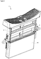
- The dryer realized in order to attain the aim of the present invention is illustrated in the attached figures, where:
-
Figure 1 - is the front partial view of a dryer. -
Figure 2 - is the perspective view of a filter. -
Figure 3 - is the view of a filter from another angle. - The elements illustrated in the figures are numbered as follows:
- 1. Dryer
- 2. Body
- 3. Housing
- 4. Filter
- 5. Scraper
- 6. Gear channel
- 7. Gear
- 8. Motor
- 9. Slot
- 10. Locking member
- 11. Connection member
- 12. Magnetic member
- 13. Hole
- 14. Bag
- 15. Fan
- The dryer (1) comprises a body (2); a housing (3) which is disposed on the body (2); a filter (4) which is placed into the housing (3) and which retains the fibers generated during the drying process; and a scraper (5) which scrapes the fibers accumulated on the filter (4). The filter (4) is placed into the housing (3) provided on the body (2). The air which is circulated during the drying process passes through the filer (4) and continues its circulation through the lower part of the housing (3). The fibers removed from the items which are dried during this process are retained on the filter (4). The scraper (5) scrapes the fibers accumulated on the filter (4). Thus, the filter (4) is prevented from getting clogged and adversely affecting the circulation of the drying air.
- The dryer (1) of the present invention comprises the V-type filter (4); two gear channels (6), each attached to one of the opposite outer edges of the filter (4) and which move relative to the filter (4); the scraper (5) which connects the opposite gear channels (6) and which is provided at the inner side of the filter (4); at least one gear (7) which is disposed in the housing (3) and which engages with the gear channel (6); and at least one motor (8) which rotates the gear (7).
- In the dryer (1) of the present invention, the filter (4) has a structure called V-type or cartridge-type structure, wherein the two filtering surfaces are connected so as to create a V, and the air to be filtered enters the filter (4) through the filter (4). Thus, the fibers are accumulated on the inner surfaces of the filter (4). The gear channel (6) is attached to the outer edges of the filter (4). The gear channel (6) moves along the edge of the filter (4). The scraper (5) is fixed to the gear channels (6) provided on the edges of the filter (4) so as to be in the filter (4) and sweep/scrape both filtering surfaces. Thus, the scraper (5) can move along the direction of the air flow as the gear channels (6) move. The movement of the gear channel (6) is provided by means of a gear (7) which is fixed in the housing (3) and the motor (8) which rotates the gear (7). Since the components which enable the scraper (5) to be moved are positioned outside the filter (4), the contact of the components which create the movement with the fibers is prevented, eliminating the risk of adversely affecting the movement.
- When the filter (4) is placed into the housing (3), the gear (7) aligns with the gear channel (6) and the gear (7) engages with the gear channel (6). When the motor (8) is rotated, the gear (7) rotates in the gear channel (6) and enables the scraper (5) to scrape the surface of the filter (4) in the vertical direction. Thus, the fibers accumulated on the filter (4) are scraped and prevented from adversely affecting the circulation of the drying air.
- In an embodiment of the present invention, the dryer (1) comprises slots (9) which are arranged on the outer edges of the filter (4) and the gear channel (6) is placed into the slot (9). By means of the slots (9) provided on the edges of the filter (4), the edges of the filter (4) are hollow and thus, the gear channel (6) and the scraper (5) are enabled to be connected to each other. The gear channels (6) are attached onto the filter (4) by being inserted into the slots (9).
- In another embodiment of the present invention, the gear channel (6) is T-shaped so as to surround the slot (9) in an airtight manner. The gear channel (6) is attached onto the slots (9) preferably by being inserted from the bottom side. The gear channel (6) is inserted into the slot (9) from the narrow neck section of the T-shape and the upper section of the T-shape remains in the filter (4), providing sealing.
- In different embodiments of the present invention, the dryer (1) comprises locking members (10) which prevent the gear channels (6) and the scraper (5) from moving relative to each other. The gear channels (6) arranged at two sides of the filter (4) is connected to the scraper (5) which is positioned in the filter (4). The scraper (5) moves together with the gear channel (6). In order to enable the filter (4) to be properly scraped, the scraper (5) has to be prevented from making movements like twisting etc. The scraper (5) and the gear channels (6) have matching locking means (10) which engage with each other so as to enable the scraper (5) to move linearly together with the gear channels (6). Thus, the scraper (5) and the gear channels (6) move together.
- In another embodiment of the present invention, the filter (4) comprises connection members (11) which enable the same to be locked onto the housing (3). When it is desired to operate the motor (8) and move the scraper (5) to clean the filter (4), the filter (4) can also move together with the gear channels (6) if the filter (4) is not fixed. In this embodiment, when the filter (4) is placed into the housing (3), the connection members (11) fix the filter (4) to the housing (3). Thus, when the motor (8) is operated, the gear channels (6) move relative to the filter (4) and enable the scraper (5) to clean the filter (4).
- In another embodiment of the present invention, the dryer (1) comprises magnetic members (12) which are oppositely positioned on the scraper (5) or the gear channel (6) and the filter (4) so as to enable the scraper (5) to be held above. When the filter (4) is detached, the gear channels (6) can move freely on the edges of the filter (4). This may create problems for the user when the filter (4) is detached. Thus, the scraper (5) and the gear channels (6) are desired to move when the filter (4) is in the housing (3) and not to move when the filter (4) is taken out of the housing (3). In order to provide this, the magnetic members (12) are provided both on the filter (4) and on the scraper (5) or the gear channels (6). By means of the magnetic members (12), the scraper (5) is held at the upper section of the filter (4) and the gear channels (6) hold the filter (4) edges so as almost not to protrude. When the motor (8) and the gear (7) are rotated, the force exerted enables the scraper (5) to move downwards on the filter (4).
- In another embodiment of the present invention, the dryer (1) comprises holes (13) which are provided on the surface of the scraper (5) and which allow the passage of the drying air. Since filter (4) used in the dryer (1) is a commonly used V-type filter (4), the scraper (5) must not prevent the passage of the drying air. The holes (13) are provided on the scraper (5) so as to be parallel with the flow of the drying air and thus, the V-type filter (4) can be cleaned by the scraper (5) without obstructing the air flow.
- In another embodiment of the present invention, the filter (5) is produced from an elastic material. By means of the scraper (5) which is produced from an elastic material, no pressure is applied onto the surface of the filter (4) and thus, the filter (4) is prevented from getting damaged while the fibers are swept.
- In another embodiment of the present invention, the dryer (1) comprises a bag (14) which is attached to the underside of the filter (4) and which is used for collecting the fibers scraped by the scraper (5). As the scraper (5) is operated, the fibers removed from the surface of the filter (4) are collected in the bag (14) attached to the underside of the filter (4). When the bag (14) is full, the filter (4) is removed and the bag (14) is disposed or replaced after being emptied.
- In another embodiment of the present invention, the dryer (1) comprises two motors (8) which are oppositely positioned in the housing (3). The two motors (8) oppositely positioned are used to enable the scraper (5) to be smoothly moved upwards and downwards perpendicular to the surface of the filter (4). The scraper (5) is enabled to move always perpendicular to the direction of the air flow by driving the motors (8) in phase. In a version of this embodiment, the motors (8) can be driven in different phases relative to each other such that the scraper (5) is slightly twisted and thus, the filter (4) is enabled to be cleaned more effectively when necessary.
- In another embodiment of the present invention, the dryer (1) comprises a fan (15) which performs the circulation of air and stops during the operation of the scraper (5). As the gear channel (6) moves along the edge of the filter (4), the edge of the filter (4) becomes free and the sealing is disrupted. By stopping the fan (15) during the operation of the scraper (5), the flow of air is interrupted and the fibers which flutter freely are prevented from escaping through the edges of the filter (4) and being dispersed into the dryer (1).
- In another embodiment of the present invention, the scraper (5) is operated whenever the filter (4) is full. The fullness of the filter (4) can be detected by means of the state of the art sensors. When the filter (4) is full, the scraper (5) is operated.
- In another embodiment of the present invention, the scraper (5) is operated at the end of the drying process. Differently from the above-disclosed embodiment, in the dryers (1) which do not comprise sensors for detecting the fullness of the filter (4), the scraper (5) is operated after each drying process and the drying can be performed without allowing the filter (4) to get clogged.
- In the dryer (1) of the present invention, the V-type filters (4) which are widely used are enabled to be automatically cleaned by means of the scraper (5). By means of the structures of the scraper (5) and the gear channels (6) to which the same is connected, the V-type filter (4) is sealed and the air flow is not obstructed when the scraper (5) is not in use. By means of the present invention, the scraper (5) can be used without changing the structure of the filter (4) and it is sufficient to attach gear channels (6) onto the edges of the V-type filter (4).
Claims (13)
- A dryer (1) comprising a body (2); a housing (3) which is disposed on the body (2); a filter (4) which is placed into the housing (3) and which retains the fibers generated during the drying process; and a scraper (5) which scrapes the fibers accumulated on the filter (4), characterized by the V-type filter (4); two gear channels (6), each attached to one of the opposite outer edges of the filter (4) and which move relative to the filter (4); the scraper (5) which connects the opposite gear channels (6) and which is provided at the inner side of the filter (4); at least one gear (7) which is disposed in the housing (3) and which engages with the gear channel (6); and at least one motor (8) which rotates the gear (7).
- 2 - A dryer (1) as in Claim 1, characterized by slots (9) which are arranged on the outer edges of the filter (4) and the gear channel (6) which is placed into the slot (9).
- 3 - A dryer (1) as in Claim 2, characterized by the gear channel (6) which is T-shaped so as to surround the slot (9) in an airtight manner.
- 4 - A dryer (1) as in any one of the above claims, characterized by locking members (10) which prevent the gear channels (6) and the scraper (5) from moving relative to each other.
- 5 - A dryer (1) as in any one of the above claims, characterized by the filter (4) having connection members (11) which enable the same to be locked onto the housing (3).
- 6 - A dryer (1) as in any one of the above claims, characterized by magnetic members (12) which are oppositely positioned on the scraper (5) or the gear channel (6) and the filter (4) so as to enable the scraper (5) to be held above.
- 7 - A dryer (1) as in any one of the above claims, characterized by holes (13) which are provided on the surface of the scraper (5) and which allow the passage of the drying air.
- 8 - A dryer (1) as in any one of the above claims, characterized by the scraper (5) which is produced from an elastic material.
- 9 - A dryer (1) as in any one of the above claims, characterized by a bag (14) which is attached to the underside of the filter (4) and which is used for collecting the fibers scraped by the scraper (5).
- 10 - A dryer (1) as in any one of the above claims, characterized by two motors (8) which are oppositely placed in the housing (3).
- 11 - A dryer (1) as in any one of the above claims, characterized by a fan (15) which performs the circulation of air and stops during the operation of the scraper (5).
- 12 - A dryer (1) as in any one of the above claims, characterized by the scraper (5) which is operated whenever the filter (4) is full.
- 13 - A dryer (1) as in any one of the above claims, characterized by the scraper (5) which is operated at the end of the drying process.
Applications Claiming Priority (1)
| Application Number | Priority Date | Filing Date | Title |
|---|---|---|---|
| TR201916777 | 2019-10-31 |
Publications (2)
| Publication Number | Publication Date |
|---|---|
| EP3816337A1 true EP3816337A1 (en) | 2021-05-05 |
| EP3816337B1 EP3816337B1 (en) | 2024-01-03 |
Family
ID=72709196
Family Applications (1)
| Application Number | Title | Priority Date | Filing Date |
|---|---|---|---|
| EP20199421.7A Active EP3816337B1 (en) | 2019-10-31 | 2020-09-30 | A dryer comprising a self-cleaning filter |
Country Status (2)
| Country | Link |
|---|---|
| EP (1) | EP3816337B1 (en) |
| PL (1) | PL3816337T3 (en) |
Citations (5)
| Publication number | Priority date | Publication date | Assignee | Title |
|---|---|---|---|---|
| US20070256317A1 (en) | 2006-05-05 | 2007-11-08 | Michael Johnson | Clothes dryer lint screen assembly with built in lint scraper blade |
| EP2126187A1 (en) | 2006-12-19 | 2009-12-02 | BSH Bosch und Siemens Hausgeräte GmbH | Method and device for drying laundry by means of an air current, and household appliance containing such a device |
| WO2010071355A2 (en) * | 2008-12-17 | 2010-06-24 | Lg Electronics Inc. | Dryer and foreign material removing apparatus thereof |
| EP2749689A1 (en) * | 2012-12-31 | 2014-07-02 | LG Electronics Inc. | Laundry treatment apparatus |
| EP3392398A1 (en) * | 2017-04-21 | 2018-10-24 | Candy S.p.A. | Laundry dryer |
-
2020
- 2020-09-30 EP EP20199421.7A patent/EP3816337B1/en active Active
- 2020-09-30 PL PL20199421.7T patent/PL3816337T3/en unknown
Patent Citations (6)
| Publication number | Priority date | Publication date | Assignee | Title |
|---|---|---|---|---|
| US20070256317A1 (en) | 2006-05-05 | 2007-11-08 | Michael Johnson | Clothes dryer lint screen assembly with built in lint scraper blade |
| EP2126187A1 (en) | 2006-12-19 | 2009-12-02 | BSH Bosch und Siemens Hausgeräte GmbH | Method and device for drying laundry by means of an air current, and household appliance containing such a device |
| WO2010071355A2 (en) * | 2008-12-17 | 2010-06-24 | Lg Electronics Inc. | Dryer and foreign material removing apparatus thereof |
| EP2376702A2 (en) | 2008-12-17 | 2011-10-19 | LG Electronics Inc. | Dryer and foreign material removing apparatus thereof |
| EP2749689A1 (en) * | 2012-12-31 | 2014-07-02 | LG Electronics Inc. | Laundry treatment apparatus |
| EP3392398A1 (en) * | 2017-04-21 | 2018-10-24 | Candy S.p.A. | Laundry dryer |
Also Published As
| Publication number | Publication date |
|---|---|
| PL3816337T3 (en) | 2024-05-20 |
| EP3816337B1 (en) | 2024-01-03 |
Similar Documents
| Publication | Publication Date | Title |
|---|---|---|
| RU2257832C2 (en) | Dust catcher for vacuum cleaner | |
| US6598263B2 (en) | Vacuum cleaner dirt collecting system with filter cleaning devices | |
| US5535478A (en) | Cleaning tool for removing lint from clothes dryers | |
| CN110284307B (en) | Clothes treatment equipment and filtering device thereof | |
| TWI661098B (en) | Filter device for washing machine and washing machine equipped with the same | |
| CN113144709B (en) | Water-conducting household appliances | |
| EP3392398A1 (en) | Laundry dryer | |
| CN116369805A (en) | Cleaning equipment, cleaning system and control method | |
| JP7010625B2 (en) | Clothes dryer | |
| JP5903539B2 (en) | Washing machine | |
| EP3530336B1 (en) | Self-cleaning filter | |
| US3236032A (en) | Vacuum cleaner with filter cleaning means | |
| EP3816337B1 (en) | A dryer comprising a self-cleaning filter | |
| CN112301697A (en) | Clothes treatment equipment and filtering device thereof | |
| CN115945002B (en) | Self-cleaning filter device and clothes dryer having the same | |
| KR20120079871A (en) | The hair dryer which is filtering system | |
| TWI825605B (en) | Cleaner | |
| CN112190206A (en) | Electric mop cleaning device | |
| KR20140144864A (en) | Vacuum Cleaner | |
| CN214198928U (en) | Filter equipment and have its air conditioner | |
| KR100833885B1 (en) | Hair Dryer with Hair Cleaning | |
| CN107327927A (en) | Air conditioner room unit and the filtering net cleaning brush for air conditioner | |
| CN110438776B (en) | Clothes treatment equipment and filtering device thereof | |
| CN218833951U (en) | Self-cleaning filtering device and clothes dryer with same | |
| CN114754457B (en) | Dust collector and have its air conditioning indoor set |
Legal Events
| Date | Code | Title | Description |
|---|---|---|---|
| PUAI | Public reference made under article 153(3) epc to a published international application that has entered the european phase |
Free format text: ORIGINAL CODE: 0009012 |
|
| STAA | Information on the status of an ep patent application or granted ep patent |
Free format text: STATUS: REQUEST FOR EXAMINATION WAS MADE |
|
| 17P | Request for examination filed |
Effective date: 20200930 |
|
| AK | Designated contracting states |
Kind code of ref document: A1 Designated state(s): AL AT BE BG CH CY CZ DE DK EE ES FI FR GB GR HR HU IE IS IT LI LT LU LV MC MK MT NL NO PL PT RO RS SE SI SK SM TR |
|
| RIC1 | Information provided on ipc code assigned before grant |
Ipc: D06F 58/22 20060101AFI20230727BHEP |
|
| GRAP | Despatch of communication of intention to grant a patent |
Free format text: ORIGINAL CODE: EPIDOSNIGR1 |
|
| STAA | Information on the status of an ep patent application or granted ep patent |
Free format text: STATUS: GRANT OF PATENT IS INTENDED |
|
| INTG | Intention to grant announced |
Effective date: 20230914 |
|
| GRAS | Grant fee paid |
Free format text: ORIGINAL CODE: EPIDOSNIGR3 |
|
| GRAA | (expected) grant |
Free format text: ORIGINAL CODE: 0009210 |
|
| STAA | Information on the status of an ep patent application or granted ep patent |
Free format text: STATUS: THE PATENT HAS BEEN GRANTED |
|
| AK | Designated contracting states |
Kind code of ref document: B1 Designated state(s): AL AT BE BG CH CY CZ DE DK EE ES FI FR GB GR HR HU IE IS IT LI LT LU LV MC MK MT NL NO PL PT RO RS SE SI SK SM TR |
|
| REG | Reference to a national code |
Ref country code: GB Ref legal event code: FG4D |
|
| REG | Reference to a national code |
Ref country code: DE Ref legal event code: R096 Ref document number: 602020023721 Country of ref document: DE |
|
| REG | Reference to a national code |
Ref country code: CH Ref legal event code: EP |
|
| REG | Reference to a national code |
Ref country code: IE Ref legal event code: FG4D |
|
| REG | Reference to a national code |
Ref country code: LT Ref legal event code: MG9D |
|
| PG25 | Lapsed in a contracting state [announced via postgrant information from national office to epo] |
Ref country code: ES Free format text: LAPSE BECAUSE OF FAILURE TO SUBMIT A TRANSLATION OF THE DESCRIPTION OR TO PAY THE FEE WITHIN THE PRESCRIBED TIME-LIMIT Effective date: 20240103 |
|
| PG25 | Lapsed in a contracting state [announced via postgrant information from national office to epo] |
Ref country code: ES Free format text: LAPSE BECAUSE OF FAILURE TO SUBMIT A TRANSLATION OF THE DESCRIPTION OR TO PAY THE FEE WITHIN THE PRESCRIBED TIME-LIMIT Effective date: 20240103 |
|
| REG | Reference to a national code |
Ref country code: NL Ref legal event code: MP Effective date: 20240103 |
|
| REG | Reference to a national code |
Ref country code: AT Ref legal event code: MK05 Ref document number: 1646880 Country of ref document: AT Kind code of ref document: T Effective date: 20240103 |
|
| PG25 | Lapsed in a contracting state [announced via postgrant information from national office to epo] |
Ref country code: NL Free format text: LAPSE BECAUSE OF FAILURE TO SUBMIT A TRANSLATION OF THE DESCRIPTION OR TO PAY THE FEE WITHIN THE PRESCRIBED TIME-LIMIT Effective date: 20240103 |
|
| PG25 | Lapsed in a contracting state [announced via postgrant information from national office to epo] |
Ref country code: NL Free format text: LAPSE BECAUSE OF FAILURE TO SUBMIT A TRANSLATION OF THE DESCRIPTION OR TO PAY THE FEE WITHIN THE PRESCRIBED TIME-LIMIT Effective date: 20240103 |
|
| PG25 | Lapsed in a contracting state [announced via postgrant information from national office to epo] |
Ref country code: IS Free format text: LAPSE BECAUSE OF FAILURE TO SUBMIT A TRANSLATION OF THE DESCRIPTION OR TO PAY THE FEE WITHIN THE PRESCRIBED TIME-LIMIT Effective date: 20240503 |
|
| PG25 | Lapsed in a contracting state [announced via postgrant information from national office to epo] |
Ref country code: LT Free format text: LAPSE BECAUSE OF FAILURE TO SUBMIT A TRANSLATION OF THE DESCRIPTION OR TO PAY THE FEE WITHIN THE PRESCRIBED TIME-LIMIT Effective date: 20240103 |
|
| PG25 | Lapsed in a contracting state [announced via postgrant information from national office to epo] |
Ref country code: GR Free format text: LAPSE BECAUSE OF FAILURE TO SUBMIT A TRANSLATION OF THE DESCRIPTION OR TO PAY THE FEE WITHIN THE PRESCRIBED TIME-LIMIT Effective date: 20240404 |
|
| PG25 | Lapsed in a contracting state [announced via postgrant information from national office to epo] |
Ref country code: HR Free format text: LAPSE BECAUSE OF FAILURE TO SUBMIT A TRANSLATION OF THE DESCRIPTION OR TO PAY THE FEE WITHIN THE PRESCRIBED TIME-LIMIT Effective date: 20240103 Ref country code: RS Free format text: LAPSE BECAUSE OF FAILURE TO SUBMIT A TRANSLATION OF THE DESCRIPTION OR TO PAY THE FEE WITHIN THE PRESCRIBED TIME-LIMIT Effective date: 20240403 |
|
| PG25 | Lapsed in a contracting state [announced via postgrant information from national office to epo] |
Ref country code: AT Free format text: LAPSE BECAUSE OF FAILURE TO SUBMIT A TRANSLATION OF THE DESCRIPTION OR TO PAY THE FEE WITHIN THE PRESCRIBED TIME-LIMIT Effective date: 20240103 Ref country code: CZ Free format text: LAPSE BECAUSE OF FAILURE TO SUBMIT A TRANSLATION OF THE DESCRIPTION OR TO PAY THE FEE WITHIN THE PRESCRIBED TIME-LIMIT Effective date: 20240103 |
|
| PG25 | Lapsed in a contracting state [announced via postgrant information from national office to epo] |
Ref country code: RS Free format text: LAPSE BECAUSE OF FAILURE TO SUBMIT A TRANSLATION OF THE DESCRIPTION OR TO PAY THE FEE WITHIN THE PRESCRIBED TIME-LIMIT Effective date: 20240403 Ref country code: NO Free format text: LAPSE BECAUSE OF FAILURE TO SUBMIT A TRANSLATION OF THE DESCRIPTION OR TO PAY THE FEE WITHIN THE PRESCRIBED TIME-LIMIT Effective date: 20240403 Ref country code: LT Free format text: LAPSE BECAUSE OF FAILURE TO SUBMIT A TRANSLATION OF THE DESCRIPTION OR TO PAY THE FEE WITHIN THE PRESCRIBED TIME-LIMIT Effective date: 20240103 Ref country code: IS Free format text: LAPSE BECAUSE OF FAILURE TO SUBMIT A TRANSLATION OF THE DESCRIPTION OR TO PAY THE FEE WITHIN THE PRESCRIBED TIME-LIMIT Effective date: 20240503 Ref country code: HR Free format text: LAPSE BECAUSE OF FAILURE TO SUBMIT A TRANSLATION OF THE DESCRIPTION OR TO PAY THE FEE WITHIN THE PRESCRIBED TIME-LIMIT Effective date: 20240103 Ref country code: GR Free format text: LAPSE BECAUSE OF FAILURE TO SUBMIT A TRANSLATION OF THE DESCRIPTION OR TO PAY THE FEE WITHIN THE PRESCRIBED TIME-LIMIT Effective date: 20240404 Ref country code: CZ Free format text: LAPSE BECAUSE OF FAILURE TO SUBMIT A TRANSLATION OF THE DESCRIPTION OR TO PAY THE FEE WITHIN THE PRESCRIBED TIME-LIMIT Effective date: 20240103 Ref country code: BG Free format text: LAPSE BECAUSE OF FAILURE TO SUBMIT A TRANSLATION OF THE DESCRIPTION OR TO PAY THE FEE WITHIN THE PRESCRIBED TIME-LIMIT Effective date: 20240103 Ref country code: AT Free format text: LAPSE BECAUSE OF FAILURE TO SUBMIT A TRANSLATION OF THE DESCRIPTION OR TO PAY THE FEE WITHIN THE PRESCRIBED TIME-LIMIT Effective date: 20240103 |
|
| PG25 | Lapsed in a contracting state [announced via postgrant information from national office to epo] |
Ref country code: PT Free format text: LAPSE BECAUSE OF FAILURE TO SUBMIT A TRANSLATION OF THE DESCRIPTION OR TO PAY THE FEE WITHIN THE PRESCRIBED TIME-LIMIT Effective date: 20240503 |
|
| PG25 | Lapsed in a contracting state [announced via postgrant information from national office to epo] |
Ref country code: SE Free format text: LAPSE BECAUSE OF FAILURE TO SUBMIT A TRANSLATION OF THE DESCRIPTION OR TO PAY THE FEE WITHIN THE PRESCRIBED TIME-LIMIT Effective date: 20240103 Ref country code: PT Free format text: LAPSE BECAUSE OF FAILURE TO SUBMIT A TRANSLATION OF THE DESCRIPTION OR TO PAY THE FEE WITHIN THE PRESCRIBED TIME-LIMIT Effective date: 20240503 Ref country code: LV Free format text: LAPSE BECAUSE OF FAILURE TO SUBMIT A TRANSLATION OF THE DESCRIPTION OR TO PAY THE FEE WITHIN THE PRESCRIBED TIME-LIMIT Effective date: 20240103 |
|
| REG | Reference to a national code |
Ref country code: DE Ref legal event code: R097 Ref document number: 602020023721 Country of ref document: DE |
|
| PG25 | Lapsed in a contracting state [announced via postgrant information from national office to epo] |
Ref country code: DK Free format text: LAPSE BECAUSE OF FAILURE TO SUBMIT A TRANSLATION OF THE DESCRIPTION OR TO PAY THE FEE WITHIN THE PRESCRIBED TIME-LIMIT Effective date: 20240103 |
|
| PG25 | Lapsed in a contracting state [announced via postgrant information from national office to epo] |
Ref country code: SM Free format text: LAPSE BECAUSE OF FAILURE TO SUBMIT A TRANSLATION OF THE DESCRIPTION OR TO PAY THE FEE WITHIN THE PRESCRIBED TIME-LIMIT Effective date: 20240103 |
|
| PG25 | Lapsed in a contracting state [announced via postgrant information from national office to epo] |
Ref country code: EE Free format text: LAPSE BECAUSE OF FAILURE TO SUBMIT A TRANSLATION OF THE DESCRIPTION OR TO PAY THE FEE WITHIN THE PRESCRIBED TIME-LIMIT Effective date: 20240103 |
|
| PG25 | Lapsed in a contracting state [announced via postgrant information from national office to epo] |
Ref country code: SK Free format text: LAPSE BECAUSE OF FAILURE TO SUBMIT A TRANSLATION OF THE DESCRIPTION OR TO PAY THE FEE WITHIN THE PRESCRIBED TIME-LIMIT Effective date: 20240103 |
|
| PG25 | Lapsed in a contracting state [announced via postgrant information from national office to epo] |
Ref country code: SM Free format text: LAPSE BECAUSE OF FAILURE TO SUBMIT A TRANSLATION OF THE DESCRIPTION OR TO PAY THE FEE WITHIN THE PRESCRIBED TIME-LIMIT Effective date: 20240103 Ref country code: SK Free format text: LAPSE BECAUSE OF FAILURE TO SUBMIT A TRANSLATION OF THE DESCRIPTION OR TO PAY THE FEE WITHIN THE PRESCRIBED TIME-LIMIT Effective date: 20240103 Ref country code: RO Free format text: LAPSE BECAUSE OF FAILURE TO SUBMIT A TRANSLATION OF THE DESCRIPTION OR TO PAY THE FEE WITHIN THE PRESCRIBED TIME-LIMIT Effective date: 20240103 Ref country code: EE Free format text: LAPSE BECAUSE OF FAILURE TO SUBMIT A TRANSLATION OF THE DESCRIPTION OR TO PAY THE FEE WITHIN THE PRESCRIBED TIME-LIMIT Effective date: 20240103 Ref country code: DK Free format text: LAPSE BECAUSE OF FAILURE TO SUBMIT A TRANSLATION OF THE DESCRIPTION OR TO PAY THE FEE WITHIN THE PRESCRIBED TIME-LIMIT Effective date: 20240103 |
|
| PLBE | No opposition filed within time limit |
Free format text: ORIGINAL CODE: 0009261 |
|
| STAA | Information on the status of an ep patent application or granted ep patent |
Free format text: STATUS: NO OPPOSITION FILED WITHIN TIME LIMIT |
|
| PG25 | Lapsed in a contracting state [announced via postgrant information from national office to epo] |
Ref country code: IT Free format text: LAPSE BECAUSE OF FAILURE TO SUBMIT A TRANSLATION OF THE DESCRIPTION OR TO PAY THE FEE WITHIN THE PRESCRIBED TIME-LIMIT Effective date: 20240103 |
|
| 26N | No opposition filed |
Effective date: 20241007 |
|
| PG25 | Lapsed in a contracting state [announced via postgrant information from national office to epo] |
Ref country code: IT Free format text: LAPSE BECAUSE OF FAILURE TO SUBMIT A TRANSLATION OF THE DESCRIPTION OR TO PAY THE FEE WITHIN THE PRESCRIBED TIME-LIMIT Effective date: 20240103 |
|
| PG25 | Lapsed in a contracting state [announced via postgrant information from national office to epo] |
Ref country code: SI Free format text: LAPSE BECAUSE OF FAILURE TO SUBMIT A TRANSLATION OF THE DESCRIPTION OR TO PAY THE FEE WITHIN THE PRESCRIBED TIME-LIMIT Effective date: 20240103 Ref country code: MC Free format text: LAPSE BECAUSE OF FAILURE TO SUBMIT A TRANSLATION OF THE DESCRIPTION OR TO PAY THE FEE WITHIN THE PRESCRIBED TIME-LIMIT Effective date: 20240103 |
|
| REG | Reference to a national code |
Ref country code: CH Ref legal event code: PL |
|
| PG25 | Lapsed in a contracting state [announced via postgrant information from national office to epo] |
Ref country code: LU Free format text: LAPSE BECAUSE OF NON-PAYMENT OF DUE FEES Effective date: 20240930 |
|
| GBPC | Gb: european patent ceased through non-payment of renewal fee |
Effective date: 20240930 |
|
| PG25 | Lapsed in a contracting state [announced via postgrant information from national office to epo] |
Ref country code: GB Free format text: LAPSE BECAUSE OF NON-PAYMENT OF DUE FEES Effective date: 20240930 |
|
| REG | Reference to a national code |
Ref country code: BE Ref legal event code: MM Effective date: 20240930 |
|
| PG25 | Lapsed in a contracting state [announced via postgrant information from national office to epo] |
Ref country code: BE Free format text: LAPSE BECAUSE OF NON-PAYMENT OF DUE FEES Effective date: 20240930 |
|
| PG25 | Lapsed in a contracting state [announced via postgrant information from national office to epo] |
Ref country code: FR Free format text: LAPSE BECAUSE OF NON-PAYMENT OF DUE FEES Effective date: 20240930 |
|
| PG25 | Lapsed in a contracting state [announced via postgrant information from national office to epo] |
Ref country code: CH Free format text: LAPSE BECAUSE OF NON-PAYMENT OF DUE FEES Effective date: 20240930 |
|
| PG25 | Lapsed in a contracting state [announced via postgrant information from national office to epo] |
Ref country code: IE Free format text: LAPSE BECAUSE OF NON-PAYMENT OF DUE FEES Effective date: 20240930 |
|
| PG25 | Lapsed in a contracting state [announced via postgrant information from national office to epo] |
Ref country code: FI Free format text: LAPSE BECAUSE OF FAILURE TO SUBMIT A TRANSLATION OF THE DESCRIPTION OR TO PAY THE FEE WITHIN THE PRESCRIBED TIME-LIMIT Effective date: 20240103 |
|
| PGFP | Annual fee paid to national office [announced via postgrant information from national office to epo] |
Ref country code: DE Payment date: 20250919 Year of fee payment: 6 |
|
| PGFP | Annual fee paid to national office [announced via postgrant information from national office to epo] |
Ref country code: PL Payment date: 20250923 Year of fee payment: 6 Ref country code: TR Payment date: 20250919 Year of fee payment: 6 |
|
| PG25 | Lapsed in a contracting state [announced via postgrant information from national office to epo] |
Ref country code: CY Free format text: LAPSE BECAUSE OF FAILURE TO SUBMIT A TRANSLATION OF THE DESCRIPTION OR TO PAY THE FEE WITHIN THE PRESCRIBED TIME-LIMIT; INVALID AB INITIO Effective date: 20200930 |
|
| PG25 | Lapsed in a contracting state [announced via postgrant information from national office to epo] |
Ref country code: HU Free format text: LAPSE BECAUSE OF FAILURE TO SUBMIT A TRANSLATION OF THE DESCRIPTION OR TO PAY THE FEE WITHIN THE PRESCRIBED TIME-LIMIT; INVALID AB INITIO Effective date: 20200930 |