EP3816218A1 - A polymer-ceramic composite and methods of making the same - Google Patents
A polymer-ceramic composite and methods of making the same Download PDFInfo
- Publication number
- EP3816218A1 EP3816218A1 EP19215620.6A EP19215620A EP3816218A1 EP 3816218 A1 EP3816218 A1 EP 3816218A1 EP 19215620 A EP19215620 A EP 19215620A EP 3816218 A1 EP3816218 A1 EP 3816218A1
- Authority
- EP
- European Patent Office
- Prior art keywords
- polymer
- composite
- ceramic
- equal
- particles
- Prior art date
- Legal status (The legal status is an assumption and is not a legal conclusion. Google has not performed a legal analysis and makes no representation as to the accuracy of the status listed.)
- Pending
Links
- 239000000919 ceramic Substances 0.000 title claims abstract description 83
- 239000002131 composite material Substances 0.000 title claims abstract description 63
- 238000000034 method Methods 0.000 title claims description 15
- 239000002245 particle Substances 0.000 claims abstract description 57
- 229920000642 polymer Polymers 0.000 claims abstract description 25
- 239000011159 matrix material Substances 0.000 claims abstract description 12
- 239000007864 aqueous solution Substances 0.000 claims description 9
- 239000000758 substrate Substances 0.000 claims description 7
- 229910052751 metal Inorganic materials 0.000 claims description 6
- 239000002184 metal Substances 0.000 claims description 6
- -1 polypropylene Polymers 0.000 claims description 6
- 229910052582 BN Inorganic materials 0.000 claims description 4
- PZNSFCLAULLKQX-UHFFFAOYSA-N Boron nitride Chemical compound N#B PZNSFCLAULLKQX-UHFFFAOYSA-N 0.000 claims description 4
- 239000004813 Perfluoroalkoxy alkane Substances 0.000 claims description 3
- 238000001035 drying Methods 0.000 claims description 3
- 238000004519 manufacturing process Methods 0.000 claims description 3
- 229920011301 perfluoro alkoxyl alkane Polymers 0.000 claims description 3
- 239000000243 solution Substances 0.000 claims description 3
- FRWYFWZENXDZMU-UHFFFAOYSA-N 2-iodoquinoline Chemical compound C1=CC=CC2=NC(I)=CC=C21 FRWYFWZENXDZMU-UHFFFAOYSA-N 0.000 claims description 2
- 239000004698 Polyethylene Substances 0.000 claims description 2
- 239000004743 Polypropylene Substances 0.000 claims description 2
- LTPBRCUWZOMYOC-UHFFFAOYSA-N beryllium oxide Inorganic materials O=[Be] LTPBRCUWZOMYOC-UHFFFAOYSA-N 0.000 claims description 2
- PMHQVHHXPFUNSP-UHFFFAOYSA-M copper(1+);methylsulfanylmethane;bromide Chemical compound Br[Cu].CSC PMHQVHHXPFUNSP-UHFFFAOYSA-M 0.000 claims description 2
- 229920002313 fluoropolymer Polymers 0.000 claims description 2
- 239000004811 fluoropolymer Substances 0.000 claims description 2
- 229920000573 polyethylene Polymers 0.000 claims description 2
- 229920001155 polypropylene Polymers 0.000 claims description 2
- 229920001343 polytetrafluoroethylene Polymers 0.000 claims description 2
- 239000004810 polytetrafluoroethylene Substances 0.000 claims description 2
- 229920000915 polyvinyl chloride Polymers 0.000 claims description 2
- 239000004800 polyvinyl chloride Substances 0.000 claims description 2
- 230000015556 catabolic process Effects 0.000 description 4
- 230000005684 electric field Effects 0.000 description 3
- 238000009413 insulation Methods 0.000 description 3
- 239000000615 nonconductor Substances 0.000 description 3
- 239000012212 insulator Substances 0.000 description 2
- 239000000463 material Substances 0.000 description 2
- 238000005299 abrasion Methods 0.000 description 1
- 238000005452 bending Methods 0.000 description 1
- 230000006835 compression Effects 0.000 description 1
- 238000007906 compression Methods 0.000 description 1
- 239000004020 conductor Substances 0.000 description 1
- 238000010586 diagram Methods 0.000 description 1
- 239000011810 insulating material Substances 0.000 description 1
- 238000005259 measurement Methods 0.000 description 1
- 238000012986 modification Methods 0.000 description 1
- 230000004048 modification Effects 0.000 description 1
- 230000010287 polarization Effects 0.000 description 1
- 239000002861 polymer material Substances 0.000 description 1
- 238000000926 separation method Methods 0.000 description 1
Images


Classifications
-
- C—CHEMISTRY; METALLURGY
- C08—ORGANIC MACROMOLECULAR COMPOUNDS; THEIR PREPARATION OR CHEMICAL WORKING-UP; COMPOSITIONS BASED THEREON
- C08K—Use of inorganic or non-macromolecular organic substances as compounding ingredients
- C08K3/00—Use of inorganic substances as compounding ingredients
- C08K3/38—Boron-containing compounds
-
- H—ELECTRICITY
- H01—ELECTRIC ELEMENTS
- H01B—CABLES; CONDUCTORS; INSULATORS; SELECTION OF MATERIALS FOR THEIR CONDUCTIVE, INSULATING OR DIELECTRIC PROPERTIES
- H01B3/00—Insulators or insulating bodies characterised by the insulating materials; Selection of materials for their insulating or dielectric properties
- H01B3/18—Insulators or insulating bodies characterised by the insulating materials; Selection of materials for their insulating or dielectric properties mainly consisting of organic substances
- H01B3/30—Insulators or insulating bodies characterised by the insulating materials; Selection of materials for their insulating or dielectric properties mainly consisting of organic substances plastics; resins; waxes
- H01B3/44—Insulators or insulating bodies characterised by the insulating materials; Selection of materials for their insulating or dielectric properties mainly consisting of organic substances plastics; resins; waxes vinyl resins; acrylic resins
- H01B3/441—Insulators or insulating bodies characterised by the insulating materials; Selection of materials for their insulating or dielectric properties mainly consisting of organic substances plastics; resins; waxes vinyl resins; acrylic resins from alkenes
-
- C—CHEMISTRY; METALLURGY
- C08—ORGANIC MACROMOLECULAR COMPOUNDS; THEIR PREPARATION OR CHEMICAL WORKING-UP; COMPOSITIONS BASED THEREON
- C08K—Use of inorganic or non-macromolecular organic substances as compounding ingredients
- C08K3/00—Use of inorganic substances as compounding ingredients
- C08K3/18—Oxygen-containing compounds, e.g. metal carbonyls
- C08K3/20—Oxides; Hydroxides
- C08K3/22—Oxides; Hydroxides of metals
-
- C—CHEMISTRY; METALLURGY
- C08—ORGANIC MACROMOLECULAR COMPOUNDS; THEIR PREPARATION OR CHEMICAL WORKING-UP; COMPOSITIONS BASED THEREON
- C08K—Use of inorganic or non-macromolecular organic substances as compounding ingredients
- C08K7/00—Use of ingredients characterised by shape
-
- H—ELECTRICITY
- H01—ELECTRIC ELEMENTS
- H01B—CABLES; CONDUCTORS; INSULATORS; SELECTION OF MATERIALS FOR THEIR CONDUCTIVE, INSULATING OR DIELECTRIC PROPERTIES
- H01B3/00—Insulators or insulating bodies characterised by the insulating materials; Selection of materials for their insulating or dielectric properties
- H01B3/002—Inhomogeneous material in general
-
- H—ELECTRICITY
- H01—ELECTRIC ELEMENTS
- H01B—CABLES; CONDUCTORS; INSULATORS; SELECTION OF MATERIALS FOR THEIR CONDUCTIVE, INSULATING OR DIELECTRIC PROPERTIES
- H01B3/00—Insulators or insulating bodies characterised by the insulating materials; Selection of materials for their insulating or dielectric properties
- H01B3/002—Inhomogeneous material in general
- H01B3/006—Other inhomogeneous material
-
- H—ELECTRICITY
- H01—ELECTRIC ELEMENTS
- H01B—CABLES; CONDUCTORS; INSULATORS; SELECTION OF MATERIALS FOR THEIR CONDUCTIVE, INSULATING OR DIELECTRIC PROPERTIES
- H01B3/00—Insulators or insulating bodies characterised by the insulating materials; Selection of materials for their insulating or dielectric properties
- H01B3/02—Insulators or insulating bodies characterised by the insulating materials; Selection of materials for their insulating or dielectric properties mainly consisting of inorganic substances
- H01B3/12—Insulators or insulating bodies characterised by the insulating materials; Selection of materials for their insulating or dielectric properties mainly consisting of inorganic substances ceramics
-
- H—ELECTRICITY
- H01—ELECTRIC ELEMENTS
- H01B—CABLES; CONDUCTORS; INSULATORS; SELECTION OF MATERIALS FOR THEIR CONDUCTIVE, INSULATING OR DIELECTRIC PROPERTIES
- H01B3/00—Insulators or insulating bodies characterised by the insulating materials; Selection of materials for their insulating or dielectric properties
- H01B3/18—Insulators or insulating bodies characterised by the insulating materials; Selection of materials for their insulating or dielectric properties mainly consisting of organic substances
- H01B3/30—Insulators or insulating bodies characterised by the insulating materials; Selection of materials for their insulating or dielectric properties mainly consisting of organic substances plastics; resins; waxes
- H01B3/44—Insulators or insulating bodies characterised by the insulating materials; Selection of materials for their insulating or dielectric properties mainly consisting of organic substances plastics; resins; waxes vinyl resins; acrylic resins
- H01B3/443—Insulators or insulating bodies characterised by the insulating materials; Selection of materials for their insulating or dielectric properties mainly consisting of organic substances plastics; resins; waxes vinyl resins; acrylic resins from vinylhalogenides or other halogenoethylenic compounds
-
- H—ELECTRICITY
- H01—ELECTRIC ELEMENTS
- H01B—CABLES; CONDUCTORS; INSULATORS; SELECTION OF MATERIALS FOR THEIR CONDUCTIVE, INSULATING OR DIELECTRIC PROPERTIES
- H01B3/00—Insulators or insulating bodies characterised by the insulating materials; Selection of materials for their insulating or dielectric properties
- H01B3/18—Insulators or insulating bodies characterised by the insulating materials; Selection of materials for their insulating or dielectric properties mainly consisting of organic substances
- H01B3/30—Insulators or insulating bodies characterised by the insulating materials; Selection of materials for their insulating or dielectric properties mainly consisting of organic substances plastics; resins; waxes
- H01B3/44—Insulators or insulating bodies characterised by the insulating materials; Selection of materials for their insulating or dielectric properties mainly consisting of organic substances plastics; resins; waxes vinyl resins; acrylic resins
- H01B3/443—Insulators or insulating bodies characterised by the insulating materials; Selection of materials for their insulating or dielectric properties mainly consisting of organic substances plastics; resins; waxes vinyl resins; acrylic resins from vinylhalogenides or other halogenoethylenic compounds
- H01B3/445—Insulators or insulating bodies characterised by the insulating materials; Selection of materials for their insulating or dielectric properties mainly consisting of organic substances plastics; resins; waxes vinyl resins; acrylic resins from vinylhalogenides or other halogenoethylenic compounds from vinylfluorides or other fluoroethylenic compounds
-
- H—ELECTRICITY
- H01—ELECTRIC ELEMENTS
- H01B—CABLES; CONDUCTORS; INSULATORS; SELECTION OF MATERIALS FOR THEIR CONDUCTIVE, INSULATING OR DIELECTRIC PROPERTIES
- H01B7/00—Insulated conductors or cables characterised by their form
- H01B7/17—Protection against damage caused by external factors, e.g. sheaths or armouring
- H01B7/29—Protection against damage caused by extremes of temperature or by flame
-
- C—CHEMISTRY; METALLURGY
- C08—ORGANIC MACROMOLECULAR COMPOUNDS; THEIR PREPARATION OR CHEMICAL WORKING-UP; COMPOSITIONS BASED THEREON
- C08K—Use of inorganic or non-macromolecular organic substances as compounding ingredients
- C08K3/00—Use of inorganic substances as compounding ingredients
- C08K3/18—Oxygen-containing compounds, e.g. metal carbonyls
- C08K3/24—Acids; Salts thereof
- C08K3/26—Carbonates; Bicarbonates
- C08K2003/262—Alkali metal carbonates
-
- C—CHEMISTRY; METALLURGY
- C08—ORGANIC MACROMOLECULAR COMPOUNDS; THEIR PREPARATION OR CHEMICAL WORKING-UP; COMPOSITIONS BASED THEREON
- C08K—Use of inorganic or non-macromolecular organic substances as compounding ingredients
- C08K3/00—Use of inorganic substances as compounding ingredients
- C08K3/38—Boron-containing compounds
- C08K2003/382—Boron-containing compounds and nitrogen
-
- C—CHEMISTRY; METALLURGY
- C08—ORGANIC MACROMOLECULAR COMPOUNDS; THEIR PREPARATION OR CHEMICAL WORKING-UP; COMPOSITIONS BASED THEREON
- C08K—Use of inorganic or non-macromolecular organic substances as compounding ingredients
- C08K3/00—Use of inorganic substances as compounding ingredients
- C08K3/38—Boron-containing compounds
- C08K2003/382—Boron-containing compounds and nitrogen
- C08K2003/385—Binary compounds of nitrogen with boron
-
- C—CHEMISTRY; METALLURGY
- C08—ORGANIC MACROMOLECULAR COMPOUNDS; THEIR PREPARATION OR CHEMICAL WORKING-UP; COMPOSITIONS BASED THEREON
- C08K—Use of inorganic or non-macromolecular organic substances as compounding ingredients
- C08K2201/00—Specific properties of additives
- C08K2201/002—Physical properties
- C08K2201/005—Additives being defined by their particle size in general
-
- H—ELECTRICITY
- H01—ELECTRIC ELEMENTS
- H01B—CABLES; CONDUCTORS; INSULATORS; SELECTION OF MATERIALS FOR THEIR CONDUCTIVE, INSULATING OR DIELECTRIC PROPERTIES
- H01B7/00—Insulated conductors or cables characterised by their form
- H01B7/42—Insulated conductors or cables characterised by their form with arrangements for heat dissipation or conduction
- H01B7/428—Heat conduction
Definitions
- Exemplary embodiments pertain to the art of polymer-ceramic composites, more particularly, to polymer-ceramic composites as insulation for high-voltage electrical cables.
- Components aboard an aircraft can include high-voltage electrical cables. These cables are often insulated due to their high voltage (e.g., up to 10 kilovolts). For example, polymers are useful as electrical insulators because they often possess both high dielectric strength and robust mechanical strength (e.g., against fracture during bending and abrasion). However, high voltage electrical cables also produce excess heat. This excess heat will need to be conducted away from the cables to prevent failure. While polymers will satisfy insulation needs as discussed above, polymers often possess poor thermal conductivity (e.g., less than 0.3 watts per meter kelvin).
- a polymer-ceramic composite comprising: ceramic particles within a polymer matrix; wherein greater than or equal to about 70% of the ceramic particles by volume experience ceramic particle to ceramic particle contact; wherein a dielectric strength of the composite is greater than or equal to about 300 kilovolts per millimeter; and wherein a thermal conductivity of the composite is greater than or equal to about 10 watts per meter kelvin.
- a high-voltage electrical cable comprising: a metal wire; and an outer sheath surrounding the metal wire, wherein the outer sheath comprises the polymer-ceramic composite.
- Also disclosed is a method of making the polymer-ceramic composite comprising: dispersing polymer particles in an aqueous solution; mixing ceramic particles into the aqueous solution; drying the aqueous solution at a temperature of about 100°C to about 150°C; and compressing the dried solution at a temperature of about 250°C to about 350°C to produce the polymer-ceramic composite.
- a polymer-ceramic composite 10 can comprise ceramic particles 12 within a polymer matrix 14. Greater than or equal to about 50% of the ceramic particles by volume can experience ceramic particle to ceramic particle contact, for example, greater than or equal to about 70%, for example, greater than or equal to about 90%, for example, greater than or equal to about 95%.
- the polymer material of the matrix 14 does not completely surround each individual ceramic particle 12. Rather, there can be a high degree of contact between ceramic particles 12 within the polymer matrix 14 (e.g., as shown in FIG. 1 ).
- this arrangement can result in robust mechanical characteristics for the composite 10, preserve a high thermal conductivity of the ceramic particles 12, and maintain a low electrical conductivity of both the ceramic particles 12 and the polymer matrix 14.
- a dielectric strength of the composite 10 can be greater than or equal to about 300 kilovolts per millimeter, for example, greater than or equal to about 350 kilovolts per millimeter, for example, greater than or equal to about 400 kilovolts per millimeter.
- a dielectric strength of the composite 10 can be, for example, about 300 kilovolts per millimeter to about 400 kilovolts per millimeter.
- dielectric can refer to an electrical insulator that can be polarized by an applied electric field. When a dielectric is placed in an electric field, electric charges do not flow through the material as they do in an electrical conductor but only slightly shift from their average equilibrium positions causing dielectric polarization.
- Dielectric strength can refer to the minimum applied electric field (i.e. the applied voltage divided by electrode separation distance) that results in electrical breakdown.
- Electrical breakdown can refer to the moment when current flows through an electrical insulator as the voltage applied across it exceeds the breakdown voltage.
- a breakdown voltage of an insulator is the minimum voltage that causes a portion of an insulator to become electrically conductive.
- a thermal conductivity of the composite 10 can be greater than or equal to about 10 watts per meter kelvin, for example, greater than or equal to about 25 watts per meter kelvin, for example, greater than or equal to about 50 watts per meter kelvin, for example, greater than or equal to about 75 watts per meter kelvin, for example, greater than or equal to about 90 watts per meter kelvin, for example, greater than or equal to about 100 watts per meter kelvin.
- a thermal conductivity of the composite 10 can be, for example, about 10 watts per meter kelvin to about 100 watts per meter kelvin.
- high thermal conductivity can drop an average temperature of the polymer-ceramic composite 10 and slow the onset of partial discharge failure.
- the ceramic particles 12 of the composite 10 can comprise boron nitride, aluminum nitride, beryllium oxide, or any combination(s) thereof.
- the ceramic particles 12 can comprise the hexagonal form of boron nitride.
- the polymer-ceramic composite 10 can comprise greater than or equal to 70% ceramic particles 12 by volume, for example, greater than or equal to 80% ceramic particles 12 by volume, for example, greater than or equal to 90% ceramic particles 12 by volume, for example, greater than or equal to 95% ceramic particles 12 by volume.
- the polymer matrix 14 of the composite 10 can comprise fluoropolymer.
- the polymer matrix 14 can comprise, for example, perfluoroalkoxy alkane, polypropylene, polyethylene, polyvinylchloride, polytetrafluoroethylene, or any combination(s) thereof.
- the polymer matrix 14 can comprise perfluoroalkoxy alkane.
- the polymer-ceramic composite 10 can comprise less than or equal to 30% polymer by volume, for example, less than or equal to 20% polymer by volume, for example, less than or equal to 10% polymer by volume, for example, less than or equal to 5% polymer by volume.
- a morphology of the ceramic particles 12 can be a platelet, an agglomerate, a flake, or any combination(s) thereof.
- an agglomerate can refer to two or more ceramic particles 12 combined together.
- a flake can refer to a portion of a ceramic particle 12 broken off from a larger ceramic particle 12.
- An average diameter 13 of the ceramic particles 12 can be about 50 nanometers to about 5000 nanometers.
- an average diameter 13 of the ceramic particles 12 can be about 70 nanometers to about 80 nanometers, about 200 nanometers to about 800 nanometers, about 4000 nanometers to about 5000 nanometer, or any combination(s) thereof.
- An aspect ratio of the ceramic particles 12 can be about 1:1 to about 100:1, for example, about 10:1 to about 90:1, for example, about 20:1 to about 80:1, for example, about 30:1 to about 70:1, for example, about 40:1 to about 60:1.
- the size and shape of the ceramic particles 12 can be measured by any suitable method, for example, a method in accordance with ISO 13318:2001.
- An orientation direction of the ceramic particles 12 can be parallel to a plane of the composite 10, perpendicular to a plane of the composite 10, random, or any combination(s) thereof.
- an orientation direction that is parallel to a plane of the composite 10 can refer to orientation in the Y direction (as shown in FIG. 1 ) and can also be referred to as "in-plane” orientation.
- An orientation direction that is perpendicular to a plane of the composite 10 can refer to orientation in the X direction (as shown in FIG. 1 ) and can also be referred to as "out-of-plane” orientation.
- An orientation that is "random" can refer to a combination of parallel and/or perpendicular orientation directions.
- the polymer-ceramic composite 10 can be anisotropic, or in other words, the composite 10 does not have identical property values in all directions.
- the more ceramic particles 12 that are oriented in a perpendicular direction the higher the thermal conductivity of the composite 10 along an "out-of-plane" orientation. This property is desirable in many applications, for example, cable insulation applications.
- greater than or equal to 50% of the ceramic particles 12 by volume can be oriented in a direction perpendicular to a plane of the composite 10, for example, greater than or equal to 70%, for example, greater than or equal to 80%, for example, greater than or equal to 90%, for example, greater than or equal to 95%.
- a substrate 16 can comprise the polymer-ceramic composite 10 deposited on a surface of the substrate 16.
- the substrate 16 can be a component of an aircraft.
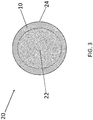
- a high-voltage electrical cable 20 can comprise a metal wire 22 and an outer sheath 24 surrounding the metal wire 22, wherein the outer sheath 24 comprises the polymer-ceramic composite 10.
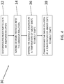
- a method 30 of making the polymer-ceramic composite 10 can comprise step 32: dispersing polymer particles in an aqueous solution.
- an average diameter 15 of the polymer particles 14 e.g., as shown in FIG. 1
- the size and shape of the polymer particles 14 can be measured by any suitable method, for example, a method in accordance with ISO 13318:2001.
- the method 30 can further comprise step 34: mixing ceramic particles into the aqueous solution.
- the method can further comprise step 36: drying the aqueous solution at a temperature of about 100°C to about 150°C, for example, about 120°C.
- the method can further comprise step 38: compressing the dried solution at a temperature of about 250°C to about 350°C, for example, about 290°C to about 310°C, for example, about 305°C, to produce the polymer-ceramic composite 10.
- a compressing time can be about 1 hour to 3 hours, for example, about 2 hours.
- compression can minimize voids between particles within the composite 10, thus resulting in higher thermal conductivity and higher dielectric strength.
Landscapes
- Chemical & Material Sciences (AREA)
- Health & Medical Sciences (AREA)
- Chemical Kinetics & Catalysis (AREA)
- Medicinal Chemistry (AREA)
- Polymers & Plastics (AREA)
- Organic Chemistry (AREA)
- Physics & Mathematics (AREA)
- Spectroscopy & Molecular Physics (AREA)
- Engineering & Computer Science (AREA)
- Ceramic Engineering (AREA)
- Inorganic Chemistry (AREA)
- Compositions Of Macromolecular Compounds (AREA)
Abstract
Description
- Exemplary embodiments pertain to the art of polymer-ceramic composites, more particularly, to polymer-ceramic composites as insulation for high-voltage electrical cables.
- Components aboard an aircraft can include high-voltage electrical cables. These cables are often insulated due to their high voltage (e.g., up to 10 kilovolts). For example, polymers are useful as electrical insulators because they often possess both high dielectric strength and robust mechanical strength (e.g., against fracture during bending and abrasion). However, high voltage electrical cables also produce excess heat. This excess heat will need to be conducted away from the cables to prevent failure. While polymers will satisfy insulation needs as discussed above, polymers often possess poor thermal conductivity (e.g., less than 0.3 watts per meter kelvin).
- Therefore, there is a need to develop a mechanically robust, composite insulating material, with a balance of both high thermal conductivity and low electrical conductivity.
- Disclosed is a polymer-ceramic composite, comprising: ceramic particles within a polymer matrix; wherein greater than or equal to about 70% of the ceramic particles by volume experience ceramic particle to ceramic particle contact; wherein a dielectric strength of the composite is greater than or equal to about 300 kilovolts per millimeter; and wherein a thermal conductivity of the composite is greater than or equal to about 10 watts per meter kelvin.
- Also disclosed is a high-voltage electrical cable, comprising: a metal wire; and an outer sheath surrounding the metal wire, wherein the outer sheath comprises the polymer-ceramic composite.
- Also disclosed is a method of making the polymer-ceramic composite, the method comprising: dispersing polymer particles in an aqueous solution; mixing ceramic particles into the aqueous solution; drying the aqueous solution at a temperature of about 100°C to about 150°C; and compressing the dried solution at a temperature of about 250°C to about 350°C to produce the polymer-ceramic composite.
- The following descriptions should not be considered limiting in any way. With reference to the accompanying drawings, like elements are numbered alike:
-
FIG. 1 is a cross-section of a polymer-ceramic composite according to an exemplary embodiment; -
FIG. 2 is a cross-section of a polymer-ceramic composite and substrate according to an exemplary embodiment; -
FIG. 3 is a cross-section of a high-voltage electrical cable according to an exemplary embodiment; and -
FIG. 4 is a flow diagram representing a method of making a polymer-ceramic composite according to an exemplary embodiment. - A detailed description of one or more embodiments of the disclosed composite and method are presented herein by way of exemplification and not limitation with reference to the Figures.
- Referring to
FIG. 1 , a polymer-ceramic composite 10 can compriseceramic particles 12 within apolymer matrix 14. Greater than or equal to about 50% of the ceramic particles by volume can experience ceramic particle to ceramic particle contact, for example, greater than or equal to about 70%, for example, greater than or equal to about 90%, for example, greater than or equal to about 95%. In other words, the polymer material of thematrix 14 does not completely surround each individualceramic particle 12. Rather, there can be a high degree of contact betweenceramic particles 12 within the polymer matrix 14 (e.g., as shown inFIG. 1 ). Not wishing to be bound by theory, this arrangement can result in robust mechanical characteristics for thecomposite 10, preserve a high thermal conductivity of theceramic particles 12, and maintain a low electrical conductivity of both theceramic particles 12 and thepolymer matrix 14. - A dielectric strength of the
composite 10 can be greater than or equal to about 300 kilovolts per millimeter, for example, greater than or equal to about 350 kilovolts per millimeter, for example, greater than or equal to about 400 kilovolts per millimeter. A dielectric strength of thecomposite 10 can be, for example, about 300 kilovolts per millimeter to about 400 kilovolts per millimeter. Here, dielectric can refer to an electrical insulator that can be polarized by an applied electric field. When a dielectric is placed in an electric field, electric charges do not flow through the material as they do in an electrical conductor but only slightly shift from their average equilibrium positions causing dielectric polarization. Dielectric strength can refer to the minimum applied electric field (i.e. the applied voltage divided by electrode separation distance) that results in electrical breakdown. Electrical breakdown can refer to the moment when current flows through an electrical insulator as the voltage applied across it exceeds the breakdown voltage. A breakdown voltage of an insulator is the minimum voltage that causes a portion of an insulator to become electrically conductive. - A thermal conductivity of the
composite 10 can be greater than or equal to about 10 watts per meter kelvin, for example, greater than or equal to about 25 watts per meter kelvin, for example, greater than or equal to about 50 watts per meter kelvin, for example, greater than or equal to about 75 watts per meter kelvin, for example, greater than or equal to about 90 watts per meter kelvin, for example, greater than or equal to about 100 watts per meter kelvin. A thermal conductivity of thecomposite 10 can be, for example, about 10 watts per meter kelvin to about 100 watts per meter kelvin. Not wishing to be bound by theory, high thermal conductivity can drop an average temperature of the polymer-ceramic composite 10 and slow the onset of partial discharge failure. - The
ceramic particles 12 of thecomposite 10 can comprise boron nitride, aluminum nitride, beryllium oxide, or any combination(s) thereof. For example, theceramic particles 12 can comprise the hexagonal form of boron nitride. The polymer-ceramic composite 10 can comprise greater than or equal to 70%ceramic particles 12 by volume, for example, greater than or equal to 80%ceramic particles 12 by volume, for example, greater than or equal to 90%ceramic particles 12 by volume, for example, greater than or equal to 95%ceramic particles 12 by volume. - The
polymer matrix 14 of thecomposite 10 can comprise fluoropolymer. Thepolymer matrix 14 can comprise, for example, perfluoroalkoxy alkane, polypropylene, polyethylene, polyvinylchloride, polytetrafluoroethylene, or any combination(s) thereof. For example, thepolymer matrix 14 can comprise perfluoroalkoxy alkane. The polymer-ceramic composite 10 can comprise less than or equal to 30% polymer by volume, for example, less than or equal to 20% polymer by volume, for example, less than or equal to 10% polymer by volume, for example, less than or equal to 5% polymer by volume. - A morphology of the
ceramic particles 12 can be a platelet, an agglomerate, a flake, or any combination(s) thereof. For example, an agglomerate can refer to two or moreceramic particles 12 combined together. A flake can refer to a portion of aceramic particle 12 broken off from a largerceramic particle 12. Anaverage diameter 13 of theceramic particles 12 can be about 50 nanometers to about 5000 nanometers. For example, anaverage diameter 13 of theceramic particles 12 can be about 70 nanometers to about 80 nanometers, about 200 nanometers to about 800 nanometers, about 4000 nanometers to about 5000 nanometer, or any combination(s) thereof. An aspect ratio of theceramic particles 12 can be about 1:1 to about 100:1, for example, about 10:1 to about 90:1, for example, about 20:1 to about 80:1, for example, about 30:1 to about 70:1, for example, about 40:1 to about 60:1. The size and shape of theceramic particles 12 can be measured by any suitable method, for example, a method in accordance with ISO 13318:2001. - An orientation direction of the
ceramic particles 12 can be parallel to a plane of thecomposite 10, perpendicular to a plane of thecomposite 10, random, or any combination(s) thereof. For example, an orientation direction that is parallel to a plane of thecomposite 10 can refer to orientation in the Y direction (as shown inFIG. 1 ) and can also be referred to as "in-plane" orientation. An orientation direction that is perpendicular to a plane of thecomposite 10 can refer to orientation in the X direction (as shown inFIG. 1 ) and can also be referred to as "out-of-plane" orientation. An orientation that is "random" can refer to a combination of parallel and/or perpendicular orientation directions. - The polymer-
ceramic composite 10 can be anisotropic, or in other words, thecomposite 10 does not have identical property values in all directions. For example, not wishing to be bound by theory, the moreceramic particles 12 that are oriented in a perpendicular direction, the higher the thermal conductivity of thecomposite 10 along an "out-of-plane" orientation. This property is desirable in many applications, for example, cable insulation applications. For example, greater than or equal to 50% of theceramic particles 12 by volume can be oriented in a direction perpendicular to a plane of thecomposite 10, for example, greater than or equal to 70%, for example, greater than or equal to 80%, for example, greater than or equal to 90%, for example, greater than or equal to 95%. - Now referring to
FIG. 2 , asubstrate 16 can comprise the polymer-ceramic composite 10 deposited on a surface of thesubstrate 16. For example, thesubstrate 16 can be a component of an aircraft. - Now referring to
FIG. 3 , a high-voltageelectrical cable 20 can comprise ametal wire 22 and anouter sheath 24 surrounding themetal wire 22, wherein theouter sheath 24 comprises the polymer-ceramic composite 10. - Now referring to
FIG. 4 , amethod 30 of making the polymer-ceramic composite 10 can comprise step 32: dispersing polymer particles in an aqueous solution. For example, anaverage diameter 15 of the polymer particles 14 (e.g., as shown inFIG. 1 ) can be about 150 nanometers to about 250 nanometers, for example, about 200 nanometers. The size and shape of thepolymer particles 14 can be measured by any suitable method, for example, a method in accordance with ISO 13318:2001. Themethod 30 can further comprise step 34: mixing ceramic particles into the aqueous solution. The method can further comprise step 36: drying the aqueous solution at a temperature of about 100°C to about 150°C, for example, about 120°C. The method can further comprise step 38: compressing the dried solution at a temperature of about 250°C to about 350°C, for example, about 290°C to about 310°C, for example, about 305°C, to produce the polymer-ceramic composite 10. A compressing time can be about 1 hour to 3 hours, for example, about 2 hours. Not wishing to be bound by theory, compression can minimize voids between particles within the composite 10, thus resulting in higher thermal conductivity and higher dielectric strength. - The term "about" is intended to include the degree of error associated with measurement of the particular quantity based upon the equipment available at the time of filing the application.
- The terminology used herein is for the purpose of describing particular embodiments only and is not intended to be limiting of the present disclosure. As used herein, the singular forms "a", "an" and "the" are intended to include the plural forms as well, unless the context clearly indicates otherwise. It will be further understood that the terms "comprises" and/or "comprising," when used in this specification, specify the presence of stated features, integers, steps, operations, elements, and/or components (and encompasses "consist(s) of', "consisting of', "consist(s) essentially of' and "consisting essentially of'), but do not necessarily preclude the presence or addition of one or more other features, integers, steps, operations, element components, and/or groups thereof.
- While the present disclosure has been described with reference to an exemplary embodiment or embodiments, it will be understood by those skilled in the art that various changes may be made and equivalents may be substituted for elements thereof without departing from the scope of the present disclosure. In addition, many modifications may be made to adapt a particular situation or material to the teachings of the present disclosure without departing from the essential scope thereof. Therefore, it is intended that the present disclosure not be limited to the particular embodiment disclosed as the best mode contemplated for carrying out this present disclosure, but that the present disclosure will include all embodiments falling within the scope of the claims.
Claims (15)
- A polymer-ceramic composite (10), comprising:ceramic particles (12) within a polymer matrix (14);wherein greater than or equal to about 70% of the ceramic particles by volume experience ceramic particle to ceramic particle contact;wherein a dielectric strength of the composite is greater than or equal to about 300 kilovolts per millimeter; andwherein a thermal conductivity of the composite is greater than or equal to about 10 watts per meter kelvin.
- The polymer-ceramic composite of Claim 1, wherein the ceramic particles comprise boron nitride, aluminum nitride, beryllium oxide, or any combination(s) thereof, or
wherein the ceramic particles comprise hexagonal boron nitride. - The polymer-ceramic composite of any preceding Claim, wherein the polymer matrix comprises fluoropolymer, or
wherein the polymer matrix comprises perfluoroalkoxy alkane, polypropylene, polyethylene, polyvinylchloride, polytetrafluoroethylene, or any combination(s) thereof. - The polymer-ceramic composite of any preceding Claim, wherein greater than or equal to about 90% of the ceramic particles by volume experience ceramic particle to ceramic particle contact.
- The polymer-ceramic composite of any preceding Claim, wherein a dielectric strength of the composite is greater than or equal to about 400 kilovolts per millimeter.
- The polymer-ceramic composite of any preceding Claim, wherein a thermal conductivity of the composite is greater than or equal to about 75 watts per meter kelvin.
- The polymer-ceramic composite of any preceding Claim, wherein the composite comprises greater than or equal to 70% ceramic particles by volume, and/or wherein the composite comprises less than or equal to 30% polymer by volume.
- The polymer-ceramic composite of any preceding Claim, wherein a morphology of the ceramic particles is a platelet, an agglomerate, a flake, or any combination(s) thereof, and/or wherein an orientation direction of the ceramic particles is parallel to a plane of the composite, perpendicular to a plane of the composite, random, or any combination(s) thereof.
- The polymer-ceramic composite of any preceding Claim, wherein greater than or equal to 50% of the ceramic particles by volume are oriented in a direction perpendicular to a plane of the composite, and/or
wherein an average diameter of the ceramic particles is about 50 nanometers to about 5000 nanometers. - A high-voltage electrical cable, comprising: a metal wire; and an outer sheath surrounding the metal wire, wherein the outer sheath comprises the polymer-ceramic composite of any preceding Claim.
- A substrate, comprising: the polymer-ceramic composite of any preceding Claim deposited on a surface of the substrate, wherein the substrate is a component of an aircraft.
- A method of making the polymer-ceramic composite of any of claims 1 to 9, the method comprising:dispersing polymer particles in an aqueous solution;mixing ceramic particles into the aqueous solution;drying the aqueous solution at a temperature of about 100°C to about 150°C; andcompressing the dried solution at a temperature of about 250°C to about 350°C to produce the polymer-ceramic composite.
- The method of Claim 12, wherein an average diameter of the polymer particles is about 150 nanometers to about 250 nanometers.
- The method of Claim 12 or 13, wherein a compressing temperature is about 290°C to about 310°C.
- The method of any of Claims 12 to 14, wherein a compressing time is about 1 hour to 3 hours.
Applications Claiming Priority (1)
| Application Number | Priority Date | Filing Date | Title |
|---|---|---|---|
| US16/668,168 US20210130573A1 (en) | 2019-10-30 | 2019-10-30 | Polymer-ceramic composite and methods of making the same |
Publications (1)
| Publication Number | Publication Date |
|---|---|
| EP3816218A1 true EP3816218A1 (en) | 2021-05-05 |
Family
ID=68887324
Family Applications (1)
| Application Number | Title | Priority Date | Filing Date |
|---|---|---|---|
| EP19215620.6A Pending EP3816218A1 (en) | 2019-10-30 | 2019-12-12 | A polymer-ceramic composite and methods of making the same |
Country Status (2)
| Country | Link |
|---|---|
| US (1) | US20210130573A1 (en) |
| EP (1) | EP3816218A1 (en) |
Families Citing this family (1)
| Publication number | Priority date | Publication date | Assignee | Title |
|---|---|---|---|---|
| US20240321663A1 (en) * | 2023-03-22 | 2024-09-26 | Wolfspeed, Inc. | High-performance stress buffer die-coat and devices and processes implementing the same |
Citations (6)
| Publication number | Priority date | Publication date | Assignee | Title |
|---|---|---|---|---|
| EP2287244A1 (en) * | 2009-08-17 | 2011-02-23 | Laird Technologies, Inc. | Highly thermally-conductive moldable thermoplastic composites and compositions |
| US8143523B2 (en) * | 2008-10-21 | 2012-03-27 | Baker Hughes Incorporated | Downhole cable with thermally conductive polymer composites |
| WO2017012119A1 (en) * | 2015-07-23 | 2017-01-26 | Dow Global Technologies Llc | Thermally conductive core-shell structured particles |
| WO2017121118A1 (en) * | 2016-01-14 | 2017-07-20 | 中山康诺德新材料有限公司 | Method for preparating hydrolysis-resistant grafted modified ammonium polyphosphate having ultra-low water slipperiness, and application thereof |
| WO2019094238A1 (en) * | 2017-11-07 | 2019-05-16 | Rogers Corporation | Dielectric layer with improved thermally conductivity |
| US20190276310A1 (en) * | 2018-03-07 | 2019-09-12 | Rogers Corporation | Method for preparing hexagonal boron nitride by templating |
Family Cites Families (3)
| Publication number | Priority date | Publication date | Assignee | Title |
|---|---|---|---|---|
| US4266841A (en) * | 1979-10-25 | 1981-05-12 | The Bendix Corporation | High voltage cable terminal |
| EP1024175A4 (en) * | 1997-09-30 | 2001-03-14 | Ngk Insulators Ltd | Plastic/ceramic composite material and process for producing the same |
| CN110892489A (en) * | 2017-06-30 | 2020-03-17 | 沙特基础工业全球技术公司 | Thermally Conductive Electrically Insulating Coatings for Wires |
-
2019
- 2019-10-30 US US16/668,168 patent/US20210130573A1/en not_active Abandoned
- 2019-12-12 EP EP19215620.6A patent/EP3816218A1/en active Pending
Patent Citations (6)
| Publication number | Priority date | Publication date | Assignee | Title |
|---|---|---|---|---|
| US8143523B2 (en) * | 2008-10-21 | 2012-03-27 | Baker Hughes Incorporated | Downhole cable with thermally conductive polymer composites |
| EP2287244A1 (en) * | 2009-08-17 | 2011-02-23 | Laird Technologies, Inc. | Highly thermally-conductive moldable thermoplastic composites and compositions |
| WO2017012119A1 (en) * | 2015-07-23 | 2017-01-26 | Dow Global Technologies Llc | Thermally conductive core-shell structured particles |
| WO2017121118A1 (en) * | 2016-01-14 | 2017-07-20 | 中山康诺德新材料有限公司 | Method for preparating hydrolysis-resistant grafted modified ammonium polyphosphate having ultra-low water slipperiness, and application thereof |
| WO2019094238A1 (en) * | 2017-11-07 | 2019-05-16 | Rogers Corporation | Dielectric layer with improved thermally conductivity |
| US20190276310A1 (en) * | 2018-03-07 | 2019-09-12 | Rogers Corporation | Method for preparing hexagonal boron nitride by templating |
Also Published As
| Publication number | Publication date |
|---|---|
| US20210130573A1 (en) | 2021-05-06 |
Similar Documents
| Publication | Publication Date | Title |
|---|---|---|
| CN102656646B (en) | Dielectric materials with nonlinear permittivity | |
| Zhou et al. | Thermoplastic polypropylene/aluminum nitride nanocomposites with enhanced thermal conductivity and low dielectric loss | |
| Preetha et al. | Electrothermal ageing of epoxy nanocomposites | |
| Maaroufi et al. | Electrical resistivity of polymeric matrix loaded with nickel and cobalt powders | |
| Ishibe et al. | A new concept varistor with epoxy/microvaristor composite | |
| CN105308688B (en) | Materials comprising reduced graphene oxide, devices comprising such materials and methods of making such materials | |
| CN107077918A (en) | Dielectric material with enhanced breakdown strength | |
| CN110235208B (en) | Multilayer stress control articles and dry terminations for medium and high voltage cable applications | |
| MXPA06009324A (en) | Current conductor made of braided wire. | |
| US20210130573A1 (en) | Polymer-ceramic composite and methods of making the same | |
| US10777335B2 (en) | Coated electric wire for winding | |
| Sathyamoorthy et al. | Experimental investigations on breakdown in cable insulation | |
| Chaurasia et al. | Effect of graded dispersion of SiC particles on dielectric behavior of SiC/Epoxy composite | |
| US20200014274A1 (en) | Stator for electric motor | |
| Boucher et al. | Study of the influence of nonlinear parameters on the efficiency of a resistive field grading tube for cable termination | |
| Abe et al. | Dielectric properties and partial discharge inception voltage of aluminum nitride insulating substrate at high temperatures | |
| Abd Rahman et al. | Influence of SiO2 and ZrO2 Nanocomposite on the AC Breakdown Strength of Cross-linked Polyethylene (XLPE) | |
| Ozaki et al. | Evaluation of coefficient of thermal expansion and relative permittivity of TiO 2/SiO 2 epoxy composite | |
| WO2018003951A1 (en) | Coil for rotary electric machine, method for producing coil for rotary electric machine, mica tape, cured product of mica tape, and insulating article | |
| Sumereder et al. | The prospects of nanotechnology in electrical power engineering | |
| Rajendran et al. | Insulators compounded with Nano Particles | |
| NageswaraRao et al. | Design of corona mitigation device and application of ZnO microvaristor on 66kV insulators by finite element method | |
| Sarkarat et al. | Composites Part C: Open Access | |
| JP2948184B2 (en) | Prefabricated junction box for CV cable | |
| Xin et al. | Influence of nano-doped LDPE cable insulating materials on the insulation and thermal conductivity properties |
Legal Events
| Date | Code | Title | Description |
|---|---|---|---|
| PUAI | Public reference made under article 153(3) epc to a published international application that has entered the european phase |
Free format text: ORIGINAL CODE: 0009012 |
|
| STAA | Information on the status of an ep patent application or granted ep patent |
Free format text: STATUS: THE APPLICATION HAS BEEN PUBLISHED |
|
| AK | Designated contracting states |
Kind code of ref document: A1 Designated state(s): AL AT BE BG CH CY CZ DE DK EE ES FI FR GB GR HR HU IE IS IT LI LT LU LV MC MK MT NL NO PL PT RO RS SE SI SK SM TR |
|
| STAA | Information on the status of an ep patent application or granted ep patent |
Free format text: STATUS: REQUEST FOR EXAMINATION WAS MADE |
|
| 17P | Request for examination filed |
Effective date: 20211105 |
|
| RBV | Designated contracting states (corrected) |
Designated state(s): AL AT BE BG CH CY CZ DE DK EE ES FI FR GB GR HR HU IE IS IT LI LT LU LV MC MK MT NL NO PL PT RO RS SE SI SK SM TR |
|
| STAA | Information on the status of an ep patent application or granted ep patent |
Free format text: STATUS: EXAMINATION IS IN PROGRESS |
|
| 17Q | First examination report despatched |
Effective date: 20240424 |