EP3816064A1 - Hand-held member and hand-held-type article - Google Patents
Hand-held member and hand-held-type article Download PDFInfo
- Publication number
- EP3816064A1 EP3816064A1 EP19841516.8A EP19841516A EP3816064A1 EP 3816064 A1 EP3816064 A1 EP 3816064A1 EP 19841516 A EP19841516 A EP 19841516A EP 3816064 A1 EP3816064 A1 EP 3816064A1
- Authority
- EP
- European Patent Office
- Prior art keywords
- hand
- held
- covering material
- main body
- resin
- Prior art date
- Legal status (The legal status is an assumption and is not a legal conclusion. Google has not performed a legal analysis and makes no representation as to the accuracy of the status listed.)
- Granted
Links
Images


Classifications
-
- B—PERFORMING OPERATIONS; TRANSPORTING
- B25—HAND TOOLS; PORTABLE POWER-DRIVEN TOOLS; MANIPULATORS
- B25G—HANDLES FOR HAND IMPLEMENTS
- B25G1/00—Handle constructions
- B25G1/10—Handle constructions characterised by material or shape
- B25G1/102—Handle constructions characterised by material or shape the shape being specially adapted to facilitate handling or improve grip
-
- B—PERFORMING OPERATIONS; TRANSPORTING
- B25—HAND TOOLS; PORTABLE POWER-DRIVEN TOOLS; MANIPULATORS
- B25G—HANDLES FOR HAND IMPLEMENTS
- B25G3/00—Attaching handles to the implements
- B25G3/34—Attaching handles to the implements by pressing the handle on the implements; using cement or molten metal, e.g. casting, moulding, by welding or the like
-
- B—PERFORMING OPERATIONS; TRANSPORTING
- B26—HAND CUTTING TOOLS; CUTTING; SEVERING
- B26B—HAND-HELD CUTTING TOOLS NOT OTHERWISE PROVIDED FOR
- B26B3/00—Hand knives with fixed blades
-
- B—PERFORMING OPERATIONS; TRANSPORTING
- B65—CONVEYING; PACKING; STORING; HANDLING THIN OR FILAMENTARY MATERIAL
- B65D—CONTAINERS FOR STORAGE OR TRANSPORT OF ARTICLES OR MATERIALS, e.g. BAGS, BARRELS, BOTTLES, BOXES, CANS, CARTONS, CRATES, DRUMS, JARS, TANKS, HOPPERS, FORWARDING CONTAINERS; ACCESSORIES, CLOSURES, OR FITTINGS THEREFOR; PACKAGING ELEMENTS; PACKAGES
- B65D23/00—Details of bottles or jars not otherwise provided for
- B65D23/08—Coverings or external coatings
- B65D23/0885—Rigid shells for receiving the bottle or part of it
-
- B—PERFORMING OPERATIONS; TRANSPORTING
- B65—CONVEYING; PACKING; STORING; HANDLING THIN OR FILAMENTARY MATERIAL
- B65D—CONTAINERS FOR STORAGE OR TRANSPORT OF ARTICLES OR MATERIALS, e.g. BAGS, BARRELS, BOTTLES, BOXES, CANS, CARTONS, CRATES, DRUMS, JARS, TANKS, HOPPERS, FORWARDING CONTAINERS; ACCESSORIES, CLOSURES, OR FITTINGS THEREFOR; PACKAGING ELEMENTS; PACKAGES
- B65D81/00—Containers, packaging elements, or packages, for contents presenting particular transport or storage problems, or adapted to be used for non-packaging purposes after removal of contents
- B65D81/38—Containers, packaging elements, or packages, for contents presenting particular transport or storage problems, or adapted to be used for non-packaging purposes after removal of contents with thermal insulation
- B65D81/3876—Containers, packaging elements, or packages, for contents presenting particular transport or storage problems, or adapted to be used for non-packaging purposes after removal of contents with thermal insulation insulating sleeves or jackets for cans, bottles, barrels, etc.
Definitions
- the present disclosure relates to a hand-held member including a portion to be held by hand, and a hand-held-type article.
- Hand-held-type articles including: a container (a so-called mug bottle, or the like) having a space for containing liquid such as a beverage; a knife such as a kitchen knife; various kinds of tableware; and the like are often used in daily life.
- the hand-held-type article has, for example, a main body having a function such as storing a liquid, and a hand-held part joined adjacent to the main body.
- a user holds the hand-held part to hold the article, an operation such as putting a beverage or the like in and out of a container, cutting foodstuff with a kitchen knife, or the like is performed, and a function as the article is realized.
- a hand-held member of an embodiment of the present disclosure includes: a hand-held part main body; and a covering material that includes a resin material having viscoelasticity in a temperature range of 10 to 40°C and covers the hand-held part main body.
- a hand-held-type article of an embodiment of the present disclosure includes: a hand-held member having the above configuration; and a main body that is joined adjacent to the hand-held member and functions when the hand-held member is gripped.
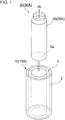
- Fig. 1 is an exploded perspective view of a hand-held-type article including a hand-held member according to a first embodiment of the present disclosure.
- Fig. 2A is a cross-sectional view showing the hand-held-type article of Fig. 1 cut in a length direction of a main body, and
- Fig. 2B is a cross-sectional view taken along line A-A of Fig. 2A .
- a hand-held member 10 covers an outer periphery of a main body 20 of a hand-held-type article 30.
- the main body 20 of the hand-held-type article 30 is a tubular container (hereinafter, also referred to as a container 20A).
- the hand-held-type article 30 (hereinafter, simply referred to as an article 30A) in this example in which the container 20A has an opening 3b for the liquid inlet/outlet on one side and has a bottom part 3a on a side opposite to the opening 3b is, for example, a container that stores various kinds of beverage while keeping temperature.
- the opening 3b described above is closed with a lid material (a so-called cap) (not shown) of a fitting type, a screw type, or the like, for example.
- a lid material a so-called cap
- liquid such as a beverage is stored in a watertight state.
- the container 20A is made of a metal material such as, for example, stainless steel.
- the container 20A may have a double wall structure with a vacuum portion sandwiched in between. In this case, heat transfer inside and outside the container can be effectively reduced.
- the article 30A is used as a mug bottle, a thermos bottle, or the like suitable for keeping temperature of a beverage.
- the article 30A provided with such a container 20A includes vacuum double molded products, for example, which are wide-mouthed bottles such as a mug bottle and a soup jar, tumbler-shaped cups, and the like.
- the hand-held member 10 (10A) covers an outer periphery of the main body 20 where the article 30A is held by a user's hand.
- the hand-held member 10A in this case has a function of reducing a slip of fingers when the article 30A is gripped and held.
- the hand-held member 10A has a function of increasing a friction coefficient of a surface portion of the article 30A such as a mug bottle, as compared to a friction coefficient of a surface of the main body (container) 20A.
- a hand-held part main body 1 is a portion that is in direct contact with an outer surface of the article 30A and is joined to the outer surface. Therefore, the hand-held part main body 1 is formed of a material that facilitates joining to the main body of the article 30A and makes it easy to secure joining strength.
- the hand-held part main body 1 is formed of a material that facilitates attachment of a covering material 2 to a surface of the hand-held part main body 1 and also makes it easy to improve strength of the attachment. Examples of such a material for forming the hand-held part main body 1 include polyolefin resin such as polypropylene resin and polyethylene resin, and resin materials such as polyester resin and vinyl resin.
- the covering material 2 covers the surface of the hand-held part main body 1 as described above. An outer surface of the covering material 2 is in direct contact with the user (fingers, and the like).
- the covering material 2 contains a resin material having viscoelasticity in a temperature range of 10 to 40°C. An outer surface portion of such a covering material 2 exhibits viscoelasticity in the temperature range described above.
- the temperature range described above is the same as or approximated to a temperature of the covering material 2 when the user's fingers or the like come into contact with the covering material 2 to use the article 30A. Therefore, when the user starts using the article 30A, the covering material 2 behaves as an elastic body. Further, with the use of the article 30A, the covering material 2 behaves as a viscous body.
- the user when starting to use the article 30A (for example, when holding a mug bottle of the article 30A relatively strongly), the user can easily grip the article 30A through the covering material 2 that behaves as an elastic body.
- the covering material 2 As the article 30A is continuously used (when a force is continuously applied to the covering material 2), an elastic modulus of the covering material 2 that behaves as a viscous body gradually becomes smaller. That is, a force of the covering material 2 to repel the gripping force tends to be small. Therefore, a burden on the user holding the article is also reduced. Further, the covering material 2 is minutely deformed easily.
- the covering material 2 is slightly deformed in accordance with a position of the finger, and the gripping of the article 30A through the covering material 2 can be easily continued.
- Such a covering material 2 has an elastic modulus of about 100 to 500 MPa, for example, when behaving as an elastic body.
- the covering material 2 can be formed of a material containing at least one selected from resin materials such as, for example, urethane resin, (meth) acrylic resin, and polyolefin resin.
- the covering material 2 may be a material in which these resin materials are mixed, or may be a copolymer. Details of the covering material 2 will be described later.
- the (meth) acrylic resin means acrylic resin or methacrylic resin.
- the hand-held member 10 can be produced, for example, as follows. First, a base material for the container 20A or the like (for example, a stainless steel container of a mug bottle) of the article 30A is prepared. A thickness of the stainless steel of the container 20A is set to, for example, about 0.25 to 0.3 mm.
- polypropylene resin powder or the like is caused to adhere to an outer surface of the base material for the container 20A, and then the polypropylene resin or the like is heated to be softened and adhere to the surface of the base material, to form the hand-held part main body 1.
- a resin material to be the covering material 2 is applied to an outer surface of the hand-held part main body 1, and this is heated and cured to form the covering material 2.
- the hand-held member 10 that covers the outer surface of the container 20A of the article 30A can be produced.
- the above base material is not limited to the container 20A.
- a metal mold for molding similar to the container 20A may be prepared, and this metal mold may be used to mold the resin material that is to be the covering material 2.
- the container 20A is fitted into the hand-held member 10 prepared as a separate part from the container 20A, and the article 30A is manufactured.
- a thickness of the hand-held part main body 1 with respect to the outer surface of the stainless steel container and the like can be appropriately set in accordance with conditions such as a material, workability at a time of formation, strength of joining to the container 20A, and economic efficiency.
- a thickness of the hand-held part main body 1 may be about 0.3 to 0.4 mm.
- a thickness of the covering material 2 can be appropriately set in accordance with conditions such as a material, workability at a time of formation, strength of joining to the hand-held part main body 1, and economic efficiency.
- the thickness of the covering material 2 may be about several tens of ⁇ m, and may be about 20 to 30 ⁇ m, as an example.
- the covering material 2 may have a region in which a dynamic friction coefficient of a surface portion with respect to an external member that is in contact with an exposed surface and is displaced from a stationary state is increased in proportion to a displacement amount of the external member from the stationary state.
- the external member is, for example, a user's finger, a user who tries to lift a mug bottle, or the like. That is, the covering material 2 has a region of a displacement amount of the fingers in which the fingers in contact with the outer surface is temporarily less likely to slip.
- the hand-held member 10A can be made to be effective in improving ease of handling, such as practicality, safety, and the like of the article 30A.
- the dynamic friction coefficient on the exposed surface of the covering material 2 with respect to the external member can be adjusted within a predetermined range, for example, by adjusting a viscosity, a softening temperature, surface roughness, and the like of the covering material 2 when behaving as a viscous body. For example, by increasing the viscosity of the covering material 2, by lowering the softening temperature, and by increasing the surface roughness, the dynamic friction coefficient of the covering material can be increased. At this time, by using together a condition (for example, an increase in the viscosity) for further increasing the dynamic friction coefficient with displacement of the external member, it is possible to form the covering material 2 having a region in which the dynamic friction coefficient increases in proportion to a displacement amount of the external member from the stationary state.
- a condition for example, an increase in the viscosity
- Fig. 3 is a graph showing a friction coefficient of the covering material 2 in the hand-held member 10 (10A) of an embodiment of the present disclosure.
- the friction coefficient has been obtained by measuring a test force in a tensile mode, by using, as a test piece, a resin material piece having the same composition as that of the covering material 2 of the embodiment.
- a load (normal reaction) by the test piece has been set to 200 gf (about 1.96 N), and a force applied to the test piece corresponding to a displacement amount (mm) has been measured as a test force (N) and graphed.
- a dynamic friction coefficient has been calculated by a formula: test force/(average value of displacement amount). As shown in this graph, it can be seen that, for example, in a range of the displacement amount of about 15 to 20 mm, the test force increases in proportion to the displacement amount, and the dynamic friction coefficient also increases.
- the dynamic friction coefficient of the surface portion of the covering material 2 with respect to the external member increases in proportion to the displacement amount of the external member.
- This dynamic friction coefficient may indicate a maximum value when the displacement amount of the external member from the stationary state is a width of a user's finger.
- the width of the finger is, for example, about 15 to 25 mm.
- the dynamic friction coefficient can be increased in an initial stage, to reduce the above-mentioned slip. Even when the user intentionally moves (displaces) the finger with respect to the covering material 2, it is also possible to effectively reduce a possibility that the hand-held part of the article 30A covered with the covering material 2 will move (slip) beyond the user's intention.
- the increasing frictional force is within a range of increase in the dynamic friction coefficient, which is very small as compared to a maximum static frictional force. Therefore, a possibility that the user feels difficult to move when moving the finger with respect to the covering material 2 is effectively reduced, which improves practicality such as ease of handling.
- the covering material 2 may be a resin material containing urethane resin.
- the covering material 2 containing urethane resin may further contain (meth) acrylic resin.
- the (meth) acrylic resin means acrylic resin or methacrylic resin.
- the covering material 2 may be a resin material containing a copolymer of urethane and (meth) acrylic.
- a molecular chain forming the resin material has a urethane-bonded portion and an acrylic-bonded portion.
- a weight average molecular weight of the molecular chain forming such a resin material is set to, for example, about 5,000 to 50,000. This makes it possible to easily adjust the dynamic friction coefficient as the covering material 2, while ensuring mechanical strength of the covering material 2.
- the covering material 2 is a resin material containing urethane resin and (meth) acrylic resin
- the covering material 2 having viscoelasticity as described above can be easily manufactured. It is also easy to increase the dynamic friction coefficient on the surface of the covering material 2 in response to displacement of the external member as described above.
- urethane resin and (meth) acrylic resin can easily have a composition in which a glass transition point is lower than 10°C and a softening point exceeds 40°C, which facilitates formation of the covering material 2 having viscoelasticity at 10 to 40°C.
- Urethane resin has a relatively small elastic modulus of about 600 to 1000 MPa, and has so-called elasticity and an elastic recovery function (a restoring force). Therefore, as described above, it is easy for the dynamic friction coefficient of the outer surface to increase in response to displacement of the external member.
- the surface portion of the covering material 2, which is easily deformed is also slightly deformed in accordance with displacement of the external member.
- the elastic recovery of the urethane resin acts on this deformation.
- a stress acting on the external member from the covering material 2 at a time of elastic recovery causes an action of suppressing displacement of the external member to some extent. This makes it easy to obtain the covering material 2 in which the dynamic friction coefficient of the outer surface increases in response to displacement of the external member.
- the above-mentioned elastic recovery action can also recover deformation erroneously generated on the outer surface of the covering material 2, to a state before the deformation. That is, the covering material 2 can be provided with a self-repairing function.
- the above deformation that occurs on the surface of the covering material 2 is a scratch, a dent, or the like that occurs, for example, when the covering material 2 located on an outermost surface of the article 30A accidentally comes into contact with the user, various utensils, metal members (a fastener held by the user, and the like), outdoor objects, and the like.
- a function of repairing/restoring such deformation can be effectively enhanced by further containing (meth) acrylic resin in the covering material 2.
- a thickness of the covering material 2 is set to 20 ⁇ m or more in consideration of ensuring the above-mentioned deformation repairing function in the covering material 2.
- the thickness of the covering material 2 is set to 20 ⁇ m or more and 30 ⁇ m or less in consideration also of strength of joining of the covering material 2 to the hand-held part main body 1, workability, productivity, and the like.
- a resin material having such a self-repairing function has, for example, the following composition. That is, urethane resin has a composition obtained by polymerizing isocyanate such as diisocyanate with a polyol such as ethylene glycol or polycarbonate diol, and has urethane bonding in a molecular chain.
- the urethane resin in this case may be copolymerized with an acrylic material such as methyl acrylate or methyl methacrylate.
- (Meth) acrylic resin is obtained by bonding, in a chain, polymerization units of methyl acrylate, methyl methacrylate, or the like, and has a composition containing a polymer chain of methyl acrylate, methyl methacrylate, or the like.
- the covering material 2 is formed of a material containing a copolymer of methyl acrylate or methyl methacrylate and the urethane resin.
- the urethane resin and the (meth) acrylic resin may further contain another resin material such as, for example, silicone resin or fluororesin, and may be a copolymer with any one of those resin materials.
- Filler particles made of an inorganic material such as silica may be added to the urethane resin and the (meth) acrylic resin.
- the article 30 is basically formed by the hand-held member 10 of the embodiment including the first embodiment, and the main body 20 joined adjacent to the hand-held member 10.
- the main body 20 realizes functions of storing liquid, keeping temperature, and the like when the hand-held member 10 is gripped.
- the main body 20 is a tubular container in which one opening 3a is closed, and the hand-held member 10A covers an outer periphery of the container (main body 20).
- the covering material 2 located on an outermost surface of the hand-held member 10 (10A), which is a handle portion, has the above-described configuration. Therefore, it is possible to provide the hand-held-type article 30 (30A) such as a liquid container (a mug bottle) that facilitates improvement of ease of handling, such as the difficulty of slipping the fingers on the hand-held member and ease of displacement.
- a liquid container a mug bottle
- Fig. 4A is an exploded plan view showing a hand-held-type article 30 (hereinafter, also simply referred to as an article 30B) including a hand-held member 10B according to a second embodiment of the present disclosure.
- Fig. 5 is a transparent plan view of the hand-held-type article 30 (not exploded) of Fig. 4A.
- Fig. 4B is a cross-sectional view showing a cross section of a portion B of Fig. 4A .
- the second embodiment differs from the first embodiment in that the article 30B is a knife such as a kitchen knife. Also in the second embodiment, a point that the hand-held member 10B covers an outer surface of a main body in a handle portion of the article 30B is similar to the case of the first embodiment.
- the point that the hand-held member 10B has a hand-held part main body 1 and a covering material 2 arranged in order from a main body 20B side as shown in the example shown in Fig. 4B is also similar to the case of the first embodiment.
- reference numeral 1 indicated by a broken line leader in Fig. 4A indicates that the hand-held member 10B internally has the hand-held part main body 1 whose surface is covered with the covering material 2.
- the main body 20 of the article 30B in this form is a blade 20B including a base part 5 in which a blade part 4 is located at one end (hereinafter, also referred to as a blade 20B).
- the hand-held member 10 covers a portion (so-called core) 5a of the base part 5 located outside the blade part 4.
- the hand-held member 10 (10B) in this form is, for example, a haft of a kitchen knife (hereinafter, also referred to as a haft 10B).
- the second embodiment is similar to the first embodiment except that the forms of the article 30B and the haft 10B are different as described above.
- the blade 20B is formed of a ceramic material, a metal material, or the like.
- the ceramic material include zirconium oxide, a composite material containing zirconium oxide as a main component, and the like.
- the article 30B is a so-called ceramic kitchen knife.
- the blade part 4 is a part that actually cuts an object such as foodstuffs and the like.
- the zirconium oxide which is a main material, may contain particles whose main component is a material having a Vickers hardness higher than that of the zirconium oxide.
- a material forming the particles is, for example, aluminum oxide or a ceramic material containing aluminum oxide as a main component.
- a shape and dimensions of the blade 20B are appropriately set in accordance with the use of the article 30B.
- a specific shape of the blade 20B may be set to a shape such as, for example, a Japanese kitchen knife such as a broad-bladed kitchen knife or a Santoku knife, a Western kitchen knife such as a chef's knife, or a Chinese kitchen knife.
- the blade 20B does not have to be limited to a shape of a kitchen knife, and may have a shape of, for example, a knife, a surgical instrument, or the like.
- a shape and dimensions of the core 5a may also be appropriately set in accordance with the use of the article 30B such as a ceramic kitchen knife.
- a hole 5b may be located in the core 5a.
- the hand-held part main body 1 and the covering material 2 included in the hand-held member 10B in the second embodiment are formed of a material similar to that of the hand-held part main body 1 and the covering material 2 included in the hand-held member 10A in the first embodiment. That is, the covering material 2 located on an outermost surface of the haft 10B has viscoelasticity as described above. This covering material 2 may have a dynamic friction coefficient as described above.
- the hand-held member 10B and the article 30B of the second embodiment can be manufactured as follows, for example.
- the blade 20B is prepared.
- alumina powder is added to zirconia powder containing, for example, yttria powder of several mol% or less, and an appropriate organic resin binder is added to make granules.
- the obtained granules are molded like the blade 20B by using a molding method such as metal molding, and then sintering is performed to obtain a zirconia sintered compact.
- the obtained zirconia sintered compact is edged by a usual method, and the blade 20B is obtained.
- the edging is set so as to obtain a predetermined blade edge angle.
- a sintering temperature may be appropriately set in accordance with the material, for example, 1300°C or higher and 1700°C or lower.
- a resin material such as polypropylene resin as the hand-held part main body 1 and a resin material such as urethane resin as the covering material 2 are sequentially attached on an outer surface of the core 5a part in the base part 5 of the blade 20B where the blade part 4 is not located.
- the hand-held-type article of the embodiment of the present disclosure it is possible to provide a hand-held-type article that facilitates ease of handling in a hand-held member that is a part to be held by hand.
- the hand-held member 10 may be colored by adding a coloring material such as a dye to the hand-held part main body 1 or the covering material 2.
- a light (visible light) reflectance of the covering material 2 may be about 70 to 80% or more on the outer surface portion, and may be more than that, for example, 90% or more. In this case, especially when the reflectance is 90% or more, an appearance of the covering material 2 becomes vivid, which is effective for improving decorativeness in appearance. This can improve decorativeness of the article 30 (30A, 30B), and can also increase an added value. For example, when the article 30 is displayed and sold together with the same type of product, it can be expected to have an effect such as easily attracting attention of purchasers.
- the covering material 2 having a light reflectance of about 70 to 80% or more on the outer surface portion contains, for example, (meth) acrylic resin as described above.
- (meth) acrylic resin as described above.
- incident light can be reflected over a relatively wide range in a thickness direction of the covering material 2. Therefore, the covering material 2 is easily made to have a light reflectance of about 70 to 80% or more on the outer surface portion.
Landscapes
- Engineering & Computer Science (AREA)
- Mechanical Engineering (AREA)
- Life Sciences & Earth Sciences (AREA)
- Forests & Forestry (AREA)
- Table Equipment (AREA)
- Knives (AREA)
- Details Of Rigid Or Semi-Rigid Containers (AREA)
Abstract
Description
- The present disclosure relates to a hand-held member including a portion to be held by hand, and a hand-held-type article.
- Hand-held-type articles including: a container (a so-called mug bottle, or the like) having a space for containing liquid such as a beverage; a knife such as a kitchen knife; various kinds of tableware; and the like are often used in daily life. The hand-held-type article has, for example, a main body having a function such as storing a liquid, and a hand-held part joined adjacent to the main body. When a user holds the hand-held part to hold the article, an operation such as putting a beverage or the like in and out of a container, cutting foodstuff with a kitchen knife, or the like is performed, and a function as the article is realized.
-
- Patent Document 1: Japanese Unexamined Utility Model Application Publication No.
S62-159854 - Patent Document 2: Japanese Unexamined Patent Publication No.
2004-358069 - A hand-held member of an embodiment of the present disclosure includes: a hand-held part main body; and a covering material that includes a resin material having viscoelasticity in a temperature range of 10 to 40°C and covers the hand-held part main body.
- A hand-held-type article of an embodiment of the present disclosure includes: a hand-held member having the above configuration; and a main body that is joined adjacent to the hand-held member and functions when the hand-held member is gripped.
-
-
Fig. 1 is an exploded perspective view of a hand-held-type article including a hand-held member according to a first embodiment of the present disclosure. -
Fig. 2A is a cross-sectional view showing the hand-held-type article ofFig. 1 cut in a length direction of a main body. -
Fig. 2B is a cross-sectional view taken along line A-A ofFig. 2A . -
Fig. 3 is a graph showing a friction coefficient of a covering material in a hand-held member according to an embodiment of the present disclosure. -
Fig. 4A is exploded plan view showing a hand-held-type article including a hand-held member according to a second embodiment of the present disclosure. -
Fig. 4B is an enlarged cross-sectional view showing a cross section of a portion B ofFig. 4A . -
Fig. 5 is a transparent plan view showing the hand-held-type article ofFig. 4A . - Hereinafter, a hand-held member and a hand-held-type article according to an embodiment of the present disclosure will be described with reference to the accompanying drawings. The figures used in the following description are schematic, and dimensional ratios and the like on the drawings do not always match the actual ones. Distinction between the top and bottom in the following description is for convenience, and does not specify the top and bottom when the hand-held member or the hand-held-type article is actually used.
-
Fig. 1 is an exploded perspective view of a hand-held-type article including a hand-held member according to a first embodiment of the present disclosure.Fig. 2A is a cross-sectional view showing the hand-held-type article ofFig. 1 cut in a length direction of a main body, andFig. 2B is a cross-sectional view taken along line A-A ofFig. 2A . - In the examples shown in
Figs. 1 ,2A, and 2B , a hand-heldmember 10 covers an outer periphery of amain body 20 of a hand-held-type article 30. Themain body 20 of the hand-held-type article 30 is a tubular container (hereinafter, also referred to as acontainer 20A). The hand-held-type article 30 (hereinafter, simply referred to as anarticle 30A) in this example in which thecontainer 20A has an opening 3b for the liquid inlet/outlet on one side and has abottom part 3a on a side opposite to the opening 3b is, for example, a container that stores various kinds of beverage while keeping temperature. The opening 3b described above is closed with a lid material (a so-called cap) (not shown) of a fitting type, a screw type, or the like, for example. As a result, an inside of thecontainer 20A is hermetically sealed, and liquid such as a beverage is stored in a watertight state. - The
container 20A is made of a metal material such as, for example, stainless steel. Thecontainer 20A may have a double wall structure with a vacuum portion sandwiched in between. In this case, heat transfer inside and outside the container can be effectively reduced. Thearticle 30A is used as a mug bottle, a thermos bottle, or the like suitable for keeping temperature of a beverage. Thearticle 30A provided with such acontainer 20A includes vacuum double molded products, for example, which are wide-mouthed bottles such as a mug bottle and a soup jar, tumbler-shaped cups, and the like. - The hand-held member 10 (10A) covers an outer periphery of the
main body 20 where thearticle 30A is held by a user's hand. The hand-heldmember 10A in this case has a function of reducing a slip of fingers when thearticle 30A is gripped and held. The hand-heldmember 10A has a function of increasing a friction coefficient of a surface portion of thearticle 30A such as a mug bottle, as compared to a friction coefficient of a surface of the main body (container) 20A. - A hand-held part
main body 1 is a portion that is in direct contact with an outer surface of thearticle 30A and is joined to the outer surface. Therefore, the hand-held partmain body 1 is formed of a material that facilitates joining to the main body of thearticle 30A and makes it easy to secure joining strength. The hand-held partmain body 1 is formed of a material that facilitates attachment of a coveringmaterial 2 to a surface of the hand-held partmain body 1 and also makes it easy to improve strength of the attachment. Examples of such a material for forming the hand-held partmain body 1 include polyolefin resin such as polypropylene resin and polyethylene resin, and resin materials such as polyester resin and vinyl resin. - The covering
material 2 covers the surface of the hand-held partmain body 1 as described above. An outer surface of the coveringmaterial 2 is in direct contact with the user (fingers, and the like). The coveringmaterial 2 contains a resin material having viscoelasticity in a temperature range of 10 to 40°C. An outer surface portion of such a coveringmaterial 2 exhibits viscoelasticity in the temperature range described above. - The temperature range described above is the same as or approximated to a temperature of the covering
material 2 when the user's fingers or the like come into contact with the coveringmaterial 2 to use thearticle 30A. Therefore, when the user starts using thearticle 30A, the coveringmaterial 2 behaves as an elastic body. Further, with the use of thearticle 30A, the coveringmaterial 2 behaves as a viscous body. - From the viewpoint of the user for this, when starting to use the
article 30A (for example, when holding a mug bottle of thearticle 30A relatively strongly), the user can easily grip thearticle 30A through the coveringmaterial 2 that behaves as an elastic body. As thearticle 30A is continuously used (when a force is continuously applied to the covering material 2), an elastic modulus of the coveringmaterial 2 that behaves as a viscous body gradually becomes smaller. That is, a force of the coveringmaterial 2 to repel the gripping force tends to be small. Therefore, a burden on the user holding the article is also reduced. Further, the coveringmaterial 2 is minutely deformed easily. Therefore, also when a way of holding thearticle 30A is changed (such as when a holding position is changed), the coveringmaterial 2 is slightly deformed in accordance with a position of the finger, and the gripping of thearticle 30A through the coveringmaterial 2 can be easily continued. - Such a covering
material 2 has an elastic modulus of about 100 to 500 MPa, for example, when behaving as an elastic body. - The covering
material 2 can be formed of a material containing at least one selected from resin materials such as, for example, urethane resin, (meth) acrylic resin, and polyolefin resin. The coveringmaterial 2 may be a material in which these resin materials are mixed, or may be a copolymer. Details of the coveringmaterial 2 will be described later. The (meth) acrylic resin means acrylic resin or methacrylic resin. - The hand-held
member 10 can be produced, for example, as follows. First, a base material for thecontainer 20A or the like (for example, a stainless steel container of a mug bottle) of thearticle 30A is prepared. A thickness of the stainless steel of thecontainer 20A is set to, for example, about 0.25 to 0.3 mm. - Next, polypropylene resin powder or the like is caused to adhere to an outer surface of the base material for the
container 20A, and then the polypropylene resin or the like is heated to be softened and adhere to the surface of the base material, to form the hand-held partmain body 1. - After that, a resin material to be the covering
material 2 is applied to an outer surface of the hand-held partmain body 1, and this is heated and cured to form the coveringmaterial 2. - By the above steps, the hand-held
member 10 that covers the outer surface of thecontainer 20A of thearticle 30A can be produced. - The above base material is not limited to the
container 20A. For example, a metal mold for molding similar to thecontainer 20A may be prepared, and this metal mold may be used to mold the resin material that is to be the coveringmaterial 2. In this case, thecontainer 20A is fitted into the hand-heldmember 10 prepared as a separate part from thecontainer 20A, and thearticle 30A is manufactured. - A thickness of the hand-held part
main body 1 with respect to the outer surface of the stainless steel container and the like (container 20A) can be appropriately set in accordance with conditions such as a material, workability at a time of formation, strength of joining to thecontainer 20A, and economic efficiency. For example, when thearticle 30A is a mug bottle, a thickness of the hand-held partmain body 1 may be about 0.3 to 0.4 mm. - A thickness of the covering
material 2 can be appropriately set in accordance with conditions such as a material, workability at a time of formation, strength of joining to the hand-held partmain body 1, and economic efficiency. For example, when the hand-held partmain body 1 is made of polypropylene resin, and the coveringmaterial 2 is made of a resin material containing urethane resin, the thickness of the coveringmaterial 2 may be about several tens of µm, and may be about 20 to 30 µm, as an example. - The covering
material 2 may have a region in which a dynamic friction coefficient of a surface portion with respect to an external member that is in contact with an exposed surface and is displaced from a stationary state is increased in proportion to a displacement amount of the external member from the stationary state. The external member is, for example, a user's finger, a user who tries to lift a mug bottle, or the like. That is, the coveringmaterial 2 has a region of a displacement amount of the fingers in which the fingers in contact with the outer surface is temporarily less likely to slip. - Therefore, when the covering
material 2 is formed on the outer surface of the hand-held partmain body 1, for example, it is possible to effectively reduce a possibility of accidentally slipping off thearticle 30A or spilling liquid such as a beverage stored in thecontainer 20A. That is, the hand-heldmember 10A can be made to be effective in improving ease of handling, such as practicality, safety, and the like of thearticle 30A. - The dynamic friction coefficient on the exposed surface of the covering
material 2 with respect to the external member can be adjusted within a predetermined range, for example, by adjusting a viscosity, a softening temperature, surface roughness, and the like of the coveringmaterial 2 when behaving as a viscous body. For example, by increasing the viscosity of the coveringmaterial 2, by lowering the softening temperature, and by increasing the surface roughness, the dynamic friction coefficient of the covering material can be increased. At this time, by using together a condition (for example, an increase in the viscosity) for further increasing the dynamic friction coefficient with displacement of the external member, it is possible to form the coveringmaterial 2 having a region in which the dynamic friction coefficient increases in proportion to a displacement amount of the external member from the stationary state. -
Fig. 3 is a graph showing a friction coefficient of the coveringmaterial 2 in the hand-held member 10 (10A) of an embodiment of the present disclosure. The friction coefficient has been obtained by measuring a test force in a tensile mode, by using, as a test piece, a resin material piece having the same composition as that of the coveringmaterial 2 of the embodiment. A load (normal reaction) by the test piece has been set to 200 gf (about 1.96 N), and a force applied to the test piece corresponding to a displacement amount (mm) has been measured as a test force (N) and graphed. A dynamic friction coefficient has been calculated by a formula: test force/(average value of displacement amount). As shown in this graph, it can be seen that, for example, in a range of the displacement amount of about 15 to 20 mm, the test force increases in proportion to the displacement amount, and the dynamic friction coefficient also increases. - As described above, the dynamic friction coefficient of the surface portion of the covering
material 2 with respect to the external member increases in proportion to the displacement amount of the external member. This dynamic friction coefficient may indicate a maximum value when the displacement amount of the external member from the stationary state is a width of a user's finger. The width of the finger is, for example, about 15 to 25 mm. - In this case, for example, when the user's finger accidentally starts slipping against the covering
material 2, the dynamic friction coefficient can be increased in an initial stage, to reduce the above-mentioned slip. Even when the user intentionally moves (displaces) the finger with respect to the coveringmaterial 2, it is also possible to effectively reduce a possibility that the hand-held part of thearticle 30A covered with the coveringmaterial 2 will move (slip) beyond the user's intention. - In this case, the increasing frictional force is within a range of increase in the dynamic friction coefficient, which is very small as compared to a maximum static frictional force. Therefore, a possibility that the user feels difficult to move when moving the finger with respect to the covering
material 2 is effectively reduced, which improves practicality such as ease of handling. - Such adjustment of the dynamic friction coefficient can be performed by, for example, the above-mentioned method of viscosity adjustment or the like of the covering
material 2. In this case, the coveringmaterial 2 may be a resin material containing urethane resin. The coveringmaterial 2 containing urethane resin may further contain (meth) acrylic resin. The (meth) acrylic resin means acrylic resin or methacrylic resin. The coveringmaterial 2 may be a resin material containing a copolymer of urethane and (meth) acrylic. In this case, a molecular chain forming the resin material has a urethane-bonded portion and an acrylic-bonded portion. A weight average molecular weight of the molecular chain forming such a resin material is set to, for example, about 5,000 to 50,000. This makes it possible to easily adjust the dynamic friction coefficient as the coveringmaterial 2, while ensuring mechanical strength of the coveringmaterial 2. - When the covering
material 2 is a resin material containing urethane resin and (meth) acrylic resin, the coveringmaterial 2 having viscoelasticity as described above can be easily manufactured. It is also easy to increase the dynamic friction coefficient on the surface of the coveringmaterial 2 in response to displacement of the external member as described above. - That is, urethane resin and (meth) acrylic resin can easily have a composition in which a glass transition point is lower than 10°C and a softening point exceeds 40°C, which facilitates formation of the covering
material 2 having viscoelasticity at 10 to 40°C. - Urethane resin has a relatively small elastic modulus of about 600 to 1000 MPa, and has so-called elasticity and an elastic recovery function (a restoring force). Therefore, as described above, it is easy for the dynamic friction coefficient of the outer surface to increase in response to displacement of the external member. In this case, the surface portion of the covering
material 2, which is easily deformed, is also slightly deformed in accordance with displacement of the external member. The elastic recovery of the urethane resin acts on this deformation. A stress acting on the external member from the coveringmaterial 2 at a time of elastic recovery causes an action of suppressing displacement of the external member to some extent. This makes it easy to obtain thecovering material 2 in which the dynamic friction coefficient of the outer surface increases in response to displacement of the external member. - When the covering
material 2 is a resin material containing urethane resin, the above-mentioned elastic recovery action can also recover deformation erroneously generated on the outer surface of the coveringmaterial 2, to a state before the deformation. That is, the coveringmaterial 2 can be provided with a self-repairing function. The above deformation that occurs on the surface of the coveringmaterial 2 is a scratch, a dent, or the like that occurs, for example, when the coveringmaterial 2 located on an outermost surface of thearticle 30A accidentally comes into contact with the user, various utensils, metal members (a fastener held by the user, and the like), outdoor objects, and the like. A function of repairing/restoring such deformation can be effectively enhanced by further containing (meth) acrylic resin in the coveringmaterial 2. - A thickness of the covering
material 2 is set to 20 µm or more in consideration of ensuring the above-mentioned deformation repairing function in the coveringmaterial 2. The thickness of the coveringmaterial 2 is set to 20 µm or more and 30 µm or less in consideration also of strength of joining of the coveringmaterial 2 to the hand-held partmain body 1, workability, productivity, and the like. - A resin material having such a self-repairing function has, for example, the following composition. That is, urethane resin has a composition obtained by polymerizing isocyanate such as diisocyanate with a polyol such as ethylene glycol or polycarbonate diol, and has urethane bonding in a molecular chain. The urethane resin in this case may be copolymerized with an acrylic material such as methyl acrylate or methyl methacrylate.
- (Meth) acrylic resin is obtained by bonding, in a chain, polymerization units of methyl acrylate, methyl methacrylate, or the like, and has a composition containing a polymer chain of methyl acrylate, methyl methacrylate, or the like. In this case, the covering
material 2 is formed of a material containing a copolymer of methyl acrylate or methyl methacrylate and the urethane resin. - The urethane resin and the (meth) acrylic resin may further contain another resin material such as, for example, silicone resin or fluororesin, and may be a copolymer with any one of those resin materials. Filler particles made of an inorganic material such as silica may be added to the urethane resin and the (meth) acrylic resin.
- As described above, the
article 30 is basically formed by the hand-heldmember 10 of the embodiment including the first embodiment, and themain body 20 joined adjacent to the hand-heldmember 10. Themain body 20 realizes functions of storing liquid, keeping temperature, and the like when the hand-heldmember 10 is gripped. In the first embodiment, themain body 20 is a tubular container in which oneopening 3a is closed, and the hand-heldmember 10A covers an outer periphery of the container (main body 20). - According to such a hand-held-type article 30 (30A) of the embodiment of the present disclosure, the covering
material 2 located on an outermost surface of the hand-held member 10 (10A), which is a handle portion, has the above-described configuration. Therefore, it is possible to provide the hand-held-type article 30 (30A) such as a liquid container (a mug bottle) that facilitates improvement of ease of handling, such as the difficulty of slipping the fingers on the hand-held member and ease of displacement. -
Fig. 4A is an exploded plan view showing a hand-held-type article 30 (hereinafter, also simply referred to as anarticle 30B) including a hand-heldmember 10B according to a second embodiment of the present disclosure.Fig. 5 is a transparent plan view of the hand-held-type article 30 (not exploded) ofFig. 4A. Fig. 4B is a cross-sectional view showing a cross section of a portion B ofFig. 4A . - The second embodiment differs from the first embodiment in that the
article 30B is a knife such as a kitchen knife. Also in the second embodiment, a point that the hand-heldmember 10B covers an outer surface of a main body in a handle portion of thearticle 30B is similar to the case of the first embodiment. The point that the hand-heldmember 10B has a hand-held partmain body 1 and a coveringmaterial 2 arranged in order from amain body 20B side as shown in the example shown inFig. 4B is also similar to the case of the first embodiment. Note thatreference numeral 1 indicated by a broken line leader inFig. 4A indicates that the hand-heldmember 10B internally has the hand-held partmain body 1 whose surface is covered with the coveringmaterial 2. - The
main body 20 of thearticle 30B in this form is ablade 20B including abase part 5 in which ablade part 4 is located at one end (hereinafter, also referred to as ablade 20B). The hand-heldmember 10 covers a portion (so-called core) 5a of thebase part 5 located outside theblade part 4. The hand-held member 10 (10B) in this form is, for example, a haft of a kitchen knife (hereinafter, also referred to as ahaft 10B). The second embodiment is similar to the first embodiment except that the forms of thearticle 30B and thehaft 10B are different as described above. - The
blade 20B is formed of a ceramic material, a metal material, or the like. Examples of the ceramic material include zirconium oxide, a composite material containing zirconium oxide as a main component, and the like. When theblade 20B is made of the ceramic material, thearticle 30B is a so-called ceramic kitchen knife. - In the
blade 20B, theblade part 4 is a part that actually cuts an object such as foodstuffs and the like. The zirconium oxide, which is a main material, may contain particles whose main component is a material having a Vickers hardness higher than that of the zirconium oxide. A material forming the particles is, for example, aluminum oxide or a ceramic material containing aluminum oxide as a main component. - A shape and dimensions of the
blade 20B are appropriately set in accordance with the use of thearticle 30B. A specific shape of theblade 20B may be set to a shape such as, for example, a Japanese kitchen knife such as a broad-bladed kitchen knife or a Santoku knife, a Western kitchen knife such as a chef's knife, or a Chinese kitchen knife. Theblade 20B does not have to be limited to a shape of a kitchen knife, and may have a shape of, for example, a knife, a surgical instrument, or the like. Further, a shape and dimensions of thecore 5a may also be appropriately set in accordance with the use of thearticle 30B such as a ceramic kitchen knife. A hole 5b may be located in thecore 5a. By inserting a part of the hand-held partmain body 1 into the hole 5b, a possibility that theblade 20B will come off from thehaft 10B is reduced. - The hand-held part
main body 1 and the coveringmaterial 2 included in the hand-heldmember 10B in the second embodiment are formed of a material similar to that of the hand-held partmain body 1 and the coveringmaterial 2 included in the hand-heldmember 10A in the first embodiment. That is, the coveringmaterial 2 located on an outermost surface of thehaft 10B has viscoelasticity as described above. This coveringmaterial 2 may have a dynamic friction coefficient as described above. - Therefore, for example, in cutting an object by using the kitchen knife of the
article 30B, the user's fingers are less likely to slip against thehaft 10B. This makes it possible to improve ease of use such as cutting workability of a kitchen knife or the like that is a hand-held-type article 30B. - Further, for example, even when a holding position of the
haft 10B of thearticle 30B is slightly changed in order to make it easier to cut foodstuffs and the like with theblade part 4, it is possible to easily change the holding position while reducing the slip of the fingers against theviscous haft 10B. Therefore, it is possible to provide a kitchen knife or the like that is advantageous for improving a characteristic such as ease of use. - In a case where the
article 30B is a ceramic kitchen knife, the hand-heldmember 10B and thearticle 30B of the second embodiment can be manufactured as follows, for example. - First, the
blade 20B is prepared. For theblade 20B, alumina powder is added to zirconia powder containing, for example, yttria powder of several mol% or less, and an appropriate organic resin binder is added to make granules. The obtained granules are molded like theblade 20B by using a molding method such as metal molding, and then sintering is performed to obtain a zirconia sintered compact. The obtained zirconia sintered compact is edged by a usual method, and theblade 20B is obtained. The edging is set so as to obtain a predetermined blade edge angle. A sintering temperature may be appropriately set in accordance with the material, for example, 1300°C or higher and 1700°C or lower. By polishing one end portion of the producedblade 20B, theblade part 4 can be formed. This allows thebase part 5 including theblade part 4 and the core 5a to be produced. - After that, similarly to the case of the first embodiment, a resin material such as polypropylene resin as the hand-held part
main body 1 and a resin material such as urethane resin as the coveringmaterial 2 are sequentially attached on an outer surface of thecore 5a part in thebase part 5 of theblade 20B where theblade part 4 is not located. By the above steps, the hand-heldmember 10B and the hand-held-type article 30B according to the second embodiment can be manufactured. - According to the hand-held-type article of the embodiment of the present disclosure, it is possible to provide a hand-held-type article that facilitates ease of handling in a hand-held member that is a part to be held by hand.
- Although the embodiments of the present disclosure have been described above, the present disclosure is not limited to the above-described embodiments, and various kinds of enhancement and improvement are possible within the scope of the claims. For example, the hand-held
member 10 may be colored by adding a coloring material such as a dye to the hand-held partmain body 1 or the coveringmaterial 2. - A light (visible light) reflectance of the covering
material 2 may be about 70 to 80% or more on the outer surface portion, and may be more than that, for example, 90% or more. In this case, especially when the reflectance is 90% or more, an appearance of the coveringmaterial 2 becomes vivid, which is effective for improving decorativeness in appearance. This can improve decorativeness of the article 30 (30A, 30B), and can also increase an added value. For example, when thearticle 30 is displayed and sold together with the same type of product, it can be expected to have an effect such as easily attracting attention of purchasers. - The covering
material 2 having a light reflectance of about 70 to 80% or more on the outer surface portion contains, for example, (meth) acrylic resin as described above. In this case, due to a light transmission effect of the (meth) acrylic resin and a light reflection effect of other component such as urethane resin, incident light can be reflected over a relatively wide range in a thickness direction of the coveringmaterial 2. Therefore, the coveringmaterial 2 is easily made to have a light reflectance of about 70 to 80% or more on the outer surface portion. -
- 1: Hand-held part main body
- 2: Covering material
- 3a: Bottom part
- 3b: Opening
- 4: Blade part
- 5: Base part
- 5a: Core
- 10: Hand-held member
- 10A: Hand-held member
- 10B: Hand-held member (haft)
- 20: Main body
- 20A: Main body (container)
- 20B: Main body (blade)
- 30: Hand-held-type article
- 30A: Article (mug bottle)
- 30B: Article (kitchen knife)
Claims (9)
- A hand-held member comprising:a hand-held part main body; anda covering material including a resin material having viscoelasticity in a temperature range of 10 to 40°C, the covering material covering the hand-held part main body.
- The hand-held member according to claim 1, further comprising an external member that is in contact with an exposed surface of the covering material, wherein the covering material has a region in which a dynamic friction coefficient of a surface portion of the covering material with respect to the external member that is displaced from a stationary state increases in proportion to a displacement amount of the external member from the stationary state.
- The hand-held member according to claim 2, wherein the dynamic friction coefficient of the surface portion of the covering material with respect to the external member indicates a maximum value when the displacement amount of the external member from the stationary state is a width of a finger.
- The hand-held member according to claim 3, wherein the width of the finger is 15 to 25 mm.
- The hand-held member according to any one of claims 1 to 4, wherein the covering material is a resin material containing urethane resin.
- The hand-held member according to claim 5, wherein the covering material further contains a resin material including (meth)acrylic resin or a copolymer of urethane resin and (meth)acrylic.
- A hand-held-type article comprising:the hand-held member according to any one of claims 1 to 6; anda main body that is joined adjacent to the hand-held member and functions when the hand-held member is gripped.
- The hand-held-type article according to claim 7, wherein
the main body is a container having a tubular shape with one opening closed, and
the hand-held member covers an outer periphery of the container. - The hand-held-type article according to claim 8, wherein
the main body is a blade having a blade part and a base part in which the blade part is located at one end, and
the hand-held member covers a portion of the base part located outside the blade part.
Applications Claiming Priority (2)
| Application Number | Priority Date | Filing Date | Title |
|---|---|---|---|
| JP2018138722 | 2018-07-24 | ||
| PCT/JP2019/028789 WO2020022314A1 (en) | 2018-07-24 | 2019-07-23 | Hand-held member and hand-held-type article |
Publications (3)
| Publication Number | Publication Date |
|---|---|
| EP3816064A1 true EP3816064A1 (en) | 2021-05-05 |
| EP3816064A4 EP3816064A4 (en) | 2021-09-29 |
| EP3816064B1 EP3816064B1 (en) | 2022-12-14 |
Family
ID=69180433
Family Applications (1)
| Application Number | Title | Priority Date | Filing Date |
|---|---|---|---|
| EP19841516.8A Active EP3816064B1 (en) | 2018-07-24 | 2019-07-23 | Hand-held member and hand-held-type article |
Country Status (6)
| Country | Link |
|---|---|
| US (1) | US11292119B2 (en) |
| EP (1) | EP3816064B1 (en) |
| JP (1) | JP6759485B2 (en) |
| CN (1) | CN112469634B (en) |
| TW (1) | TWI721509B (en) |
| WO (1) | WO2020022314A1 (en) |
Families Citing this family (1)
| Publication number | Priority date | Publication date | Assignee | Title |
|---|---|---|---|---|
| JP2023157233A (en) * | 2022-04-14 | 2023-10-26 | メビウスパッケージング株式会社 | Transparent plastic bottle suitable for returnable use |
Family Cites Families (28)
| Publication number | Priority date | Publication date | Assignee | Title |
|---|---|---|---|---|
| US3207461A (en) * | 1963-05-10 | 1965-09-21 | American Can Co | Cup holder |
| US4007527A (en) * | 1975-07-07 | 1977-02-15 | Tibbs Edward A | Utensil retaining means |
| US4167811A (en) * | 1978-03-13 | 1979-09-18 | Imperial Knife Associated Companies, Inc. | Folding knife |
| JPH0513345Y2 (en) | 1986-03-29 | 1993-04-08 | ||
| JP2824895B2 (en) * | 1993-12-22 | 1998-11-18 | 株式会社日本デキシー | Insulating paper container and method of manufacturing the same |
| US5819594A (en) * | 1996-03-05 | 1998-10-13 | Sioux Tools, Inc. | Ergonomic hand grip |
| JPH1130228A (en) * | 1997-07-11 | 1999-02-02 | Kobe Steel Ltd | Roller |
| US6610382B1 (en) * | 1998-10-05 | 2003-08-26 | 3M Innovative Properties Company | Friction control article for wet and dry applications |
| US6652941B1 (en) * | 2000-09-27 | 2003-11-25 | Bic Corporation | Grip element and method of manufacture thereof |
| JP2003019064A (en) * | 2001-07-06 | 2003-01-21 | Creative Joy:Kk | Decorative container |
| JP3083652U (en) | 2001-07-26 | 2002-02-08 | 株式会社タイキ | Three treasure plate |
| JP3719656B2 (en) | 2001-08-06 | 2005-11-24 | 昭和電線電纜株式会社 | Dust cover for sliding support |
| JP2003080163A (en) | 2001-09-14 | 2003-03-18 | Inagaki Sangyo Kk | Kitchen knife |
| JP3905062B2 (en) | 2003-06-06 | 2007-04-18 | 京セラ株式会社 | Ceramic knife |
| JP4365731B2 (en) | 2004-06-15 | 2009-11-18 | 株式会社ビービーエム | Sliding bearing device |
| JP4443463B2 (en) * | 2005-04-28 | 2010-03-31 | 北川工業株式会社 | Clamp |
| CN101278011B (en) * | 2005-08-02 | 2012-10-24 | 环球产权公司 | Silicone compositions, methods of manufacture, and articles formed therefrom |
| US20100183814A1 (en) * | 2005-08-02 | 2010-07-22 | Victor Rios | Silicone compositions, methods of manufacture, and articles formed therefrom |
| JP4880966B2 (en) * | 2005-10-03 | 2012-02-22 | 株式会社フジシールインターナショナル | Label for container having matte coating layer, and container with label |
| JP4882919B2 (en) * | 2006-08-30 | 2012-02-22 | 東洋紡績株式会社 | Heat-shrinkable polyester film, method for producing the same, and package |
| JP4672706B2 (en) * | 2007-08-31 | 2011-04-20 | 和行 久保田 | Bottle holder |
| JP3171162U (en) * | 2011-07-13 | 2011-10-20 | 株式会社レーベン販売 | Kitchen knife |
| WO2014033909A1 (en) * | 2012-08-31 | 2014-03-06 | 株式会社ユーエム工業 | Blade-replaceable saw |
| JP6179707B2 (en) | 2013-03-22 | 2017-08-16 | 株式会社フジシール | Labeled container |
| US20160084603A1 (en) * | 2014-09-23 | 2016-03-24 | Frank J. Michal | Firearm Barrel Holders |
| JP7308588B2 (en) | 2016-06-21 | 2023-07-14 | 大日本印刷株式会社 | Packaging bag with bite |
| CN110636820A (en) * | 2017-05-19 | 2019-12-31 | 3M创新有限公司 | Medical article fixation device comprising viscoelastic polymer |
| EP3663343A4 (en) * | 2017-08-03 | 2021-04-28 | DIC Corporation | PROCESS FOR THE PRODUCTION OF A POROUS OBJECT |
-
2019
- 2019-07-23 JP JP2020500669A patent/JP6759485B2/en active Active
- 2019-07-23 CN CN201980048959.3A patent/CN112469634B/en active Active
- 2019-07-23 US US17/262,428 patent/US11292119B2/en active Active
- 2019-07-23 WO PCT/JP2019/028789 patent/WO2020022314A1/en not_active Ceased
- 2019-07-23 EP EP19841516.8A patent/EP3816064B1/en active Active
- 2019-07-24 TW TW108126161A patent/TWI721509B/en active
Also Published As
| Publication number | Publication date |
|---|---|
| TWI721509B (en) | 2021-03-11 |
| CN112469634B (en) | 2021-11-19 |
| JP6759485B2 (en) | 2020-09-23 |
| US20210245355A1 (en) | 2021-08-12 |
| WO2020022314A1 (en) | 2020-01-30 |
| EP3816064B1 (en) | 2022-12-14 |
| JPWO2020022314A1 (en) | 2020-08-06 |
| CN112469634A (en) | 2021-03-09 |
| TW202007504A (en) | 2020-02-16 |
| EP3816064A4 (en) | 2021-09-29 |
| US11292119B2 (en) | 2022-04-05 |
Similar Documents
| Publication | Publication Date | Title |
|---|---|---|
| US20200262746A1 (en) | Protective cover, its use and method of making a protective cover | |
| TWI802585B (en) | Hybrid gradient-interference hardcoatings | |
| CN111164463B (en) | Hard Anti-reflection Coating | |
| EP3770649A1 (en) | High light transmission and scratch-resistant anti-reflective articles | |
| US11292119B2 (en) | Hand-held member and hand-held-type article | |
| US20160257478A1 (en) | Measuring container with heat dissipating section | |
| US20140362444A1 (en) | Articles with anti-reflective high-hardness coatings and related methods | |
| EP1157936A3 (en) | Food product container with closure | |
| US20150157154A1 (en) | Eating utensil rest | |
| WO2022125846A1 (en) | Cover glass articles for camera lens and sensor protection and apparatus with the same | |
| US12420527B2 (en) | Bendable element | |
| US20110138632A1 (en) | Spoon, knife with toothpick combination | |
| CN112469558A (en) | Redrawn glass with enhanced puncture resistance | |
| JP4939434B2 (en) | Pressure indicating structure | |
| CN112804913A (en) | Modular handle for two-stage packaging | |
| US20250366642A1 (en) | Fully transparent unbreakable drinkware | |
| CN209678099U (en) | A kind of new-type antiskid falls anti-pollution chopsticks | |
| CN2464672Y (en) | The storage structure of food containers | |
| KR200365786Y1 (en) | a cushion of absorbing shock from the bottom of vessel | |
| KR101770867B1 (en) | Interior sheet having real metal three dimensional emboss and method of manufacturing the same | |
| CN209219988U (en) | Improved pot cover | |
| CN208228741U (en) | A kind of gold stamping tableware tray of PS | |
| CN210478024U (en) | Easily take off epiphragma | |
| DE29515001U1 (en) | One-hand cutlery | |
| KR102037393B1 (en) | Foldable food container and carrier thereof |
Legal Events
| Date | Code | Title | Description |
|---|---|---|---|
| STAA | Information on the status of an ep patent application or granted ep patent |
Free format text: STATUS: THE INTERNATIONAL PUBLICATION HAS BEEN MADE |
|
| PUAI | Public reference made under article 153(3) epc to a published international application that has entered the european phase |
Free format text: ORIGINAL CODE: 0009012 |
|
| STAA | Information on the status of an ep patent application or granted ep patent |
Free format text: STATUS: REQUEST FOR EXAMINATION WAS MADE |
|
| 17P | Request for examination filed |
Effective date: 20210129 |
|
| AK | Designated contracting states |
Kind code of ref document: A1 Designated state(s): AL AT BE BG CH CY CZ DE DK EE ES FI FR GB GR HR HU IE IS IT LI LT LU LV MC MK MT NL NO PL PT RO RS SE SI SK SM TR |
|
| A4 | Supplementary search report drawn up and despatched |
Effective date: 20210827 |
|
| RIC1 | Information provided on ipc code assigned before grant |
Ipc: B25G 3/34 20060101ALI20210823BHEP Ipc: B26B 3/00 20060101ALI20210823BHEP Ipc: B25G 1/10 20060101ALI20210823BHEP Ipc: B65D 25/20 20060101AFI20210823BHEP |
|
| DAV | Request for validation of the european patent (deleted) | ||
| DAX | Request for extension of the european patent (deleted) | ||
| GRAP | Despatch of communication of intention to grant a patent |
Free format text: ORIGINAL CODE: EPIDOSNIGR1 |
|
| STAA | Information on the status of an ep patent application or granted ep patent |
Free format text: STATUS: GRANT OF PATENT IS INTENDED |
|
| INTG | Intention to grant announced |
Effective date: 20220704 |
|
| GRAS | Grant fee paid |
Free format text: ORIGINAL CODE: EPIDOSNIGR3 |
|
| GRAA | (expected) grant |
Free format text: ORIGINAL CODE: 0009210 |
|
| STAA | Information on the status of an ep patent application or granted ep patent |
Free format text: STATUS: THE PATENT HAS BEEN GRANTED |
|
| AK | Designated contracting states |
Kind code of ref document: B1 Designated state(s): AL AT BE BG CH CY CZ DE DK EE ES FI FR GB GR HR HU IE IS IT LI LT LU LV MC MK MT NL NO PL PT RO RS SE SI SK SM TR |
|
| REG | Reference to a national code |
Ref country code: GB Ref legal event code: FG4D |
|
| REG | Reference to a national code |
Ref country code: CH Ref legal event code: EP |
|
| REG | Reference to a national code |
Ref country code: DE Ref legal event code: R096 Ref document number: 602019023254 Country of ref document: DE |
|
| REG | Reference to a national code |
Ref country code: IE Ref legal event code: FG4D |
|
| REG | Reference to a national code |
Ref country code: AT Ref legal event code: REF Ref document number: 1537554 Country of ref document: AT Kind code of ref document: T Effective date: 20230115 |
|
| REG | Reference to a national code |
Ref country code: LT Ref legal event code: MG9D |
|
| REG | Reference to a national code |
Ref country code: NL Ref legal event code: MP Effective date: 20221214 |
|
| PG25 | Lapsed in a contracting state [announced via postgrant information from national office to epo] |
Ref country code: SE Free format text: LAPSE BECAUSE OF FAILURE TO SUBMIT A TRANSLATION OF THE DESCRIPTION OR TO PAY THE FEE WITHIN THE PRESCRIBED TIME-LIMIT Effective date: 20221214 Ref country code: NO Free format text: LAPSE BECAUSE OF FAILURE TO SUBMIT A TRANSLATION OF THE DESCRIPTION OR TO PAY THE FEE WITHIN THE PRESCRIBED TIME-LIMIT Effective date: 20230314 Ref country code: LT Free format text: LAPSE BECAUSE OF FAILURE TO SUBMIT A TRANSLATION OF THE DESCRIPTION OR TO PAY THE FEE WITHIN THE PRESCRIBED TIME-LIMIT Effective date: 20221214 Ref country code: FI Free format text: LAPSE BECAUSE OF FAILURE TO SUBMIT A TRANSLATION OF THE DESCRIPTION OR TO PAY THE FEE WITHIN THE PRESCRIBED TIME-LIMIT Effective date: 20221214 |
|
| REG | Reference to a national code |
Ref country code: AT Ref legal event code: MK05 Ref document number: 1537554 Country of ref document: AT Kind code of ref document: T Effective date: 20221214 |
|
| PG25 | Lapsed in a contracting state [announced via postgrant information from national office to epo] |
Ref country code: RS Free format text: LAPSE BECAUSE OF FAILURE TO SUBMIT A TRANSLATION OF THE DESCRIPTION OR TO PAY THE FEE WITHIN THE PRESCRIBED TIME-LIMIT Effective date: 20221214 Ref country code: LV Free format text: LAPSE BECAUSE OF FAILURE TO SUBMIT A TRANSLATION OF THE DESCRIPTION OR TO PAY THE FEE WITHIN THE PRESCRIBED TIME-LIMIT Effective date: 20221214 Ref country code: HR Free format text: LAPSE BECAUSE OF FAILURE TO SUBMIT A TRANSLATION OF THE DESCRIPTION OR TO PAY THE FEE WITHIN THE PRESCRIBED TIME-LIMIT Effective date: 20221214 Ref country code: GR Free format text: LAPSE BECAUSE OF FAILURE TO SUBMIT A TRANSLATION OF THE DESCRIPTION OR TO PAY THE FEE WITHIN THE PRESCRIBED TIME-LIMIT Effective date: 20230315 |
|
| P01 | Opt-out of the competence of the unified patent court (upc) registered |
Effective date: 20230508 |
|
| PG25 | Lapsed in a contracting state [announced via postgrant information from national office to epo] |
Ref country code: NL Free format text: LAPSE BECAUSE OF FAILURE TO SUBMIT A TRANSLATION OF THE DESCRIPTION OR TO PAY THE FEE WITHIN THE PRESCRIBED TIME-LIMIT Effective date: 20221214 |
|
| PG25 | Lapsed in a contracting state [announced via postgrant information from national office to epo] |
Ref country code: SM Free format text: LAPSE BECAUSE OF FAILURE TO SUBMIT A TRANSLATION OF THE DESCRIPTION OR TO PAY THE FEE WITHIN THE PRESCRIBED TIME-LIMIT Effective date: 20221214 Ref country code: RO Free format text: LAPSE BECAUSE OF FAILURE TO SUBMIT A TRANSLATION OF THE DESCRIPTION OR TO PAY THE FEE WITHIN THE PRESCRIBED TIME-LIMIT Effective date: 20221214 Ref country code: PT Free format text: LAPSE BECAUSE OF FAILURE TO SUBMIT A TRANSLATION OF THE DESCRIPTION OR TO PAY THE FEE WITHIN THE PRESCRIBED TIME-LIMIT Effective date: 20230414 Ref country code: ES Free format text: LAPSE BECAUSE OF FAILURE TO SUBMIT A TRANSLATION OF THE DESCRIPTION OR TO PAY THE FEE WITHIN THE PRESCRIBED TIME-LIMIT Effective date: 20221214 Ref country code: EE Free format text: LAPSE BECAUSE OF FAILURE TO SUBMIT A TRANSLATION OF THE DESCRIPTION OR TO PAY THE FEE WITHIN THE PRESCRIBED TIME-LIMIT Effective date: 20221214 Ref country code: CZ Free format text: LAPSE BECAUSE OF FAILURE TO SUBMIT A TRANSLATION OF THE DESCRIPTION OR TO PAY THE FEE WITHIN THE PRESCRIBED TIME-LIMIT Effective date: 20221214 Ref country code: AT Free format text: LAPSE BECAUSE OF FAILURE TO SUBMIT A TRANSLATION OF THE DESCRIPTION OR TO PAY THE FEE WITHIN THE PRESCRIBED TIME-LIMIT Effective date: 20221214 |
|
| PG25 | Lapsed in a contracting state [announced via postgrant information from national office to epo] |
Ref country code: SK Free format text: LAPSE BECAUSE OF FAILURE TO SUBMIT A TRANSLATION OF THE DESCRIPTION OR TO PAY THE FEE WITHIN THE PRESCRIBED TIME-LIMIT Effective date: 20221214 Ref country code: PL Free format text: LAPSE BECAUSE OF FAILURE TO SUBMIT A TRANSLATION OF THE DESCRIPTION OR TO PAY THE FEE WITHIN THE PRESCRIBED TIME-LIMIT Effective date: 20221214 Ref country code: IS Free format text: LAPSE BECAUSE OF FAILURE TO SUBMIT A TRANSLATION OF THE DESCRIPTION OR TO PAY THE FEE WITHIN THE PRESCRIBED TIME-LIMIT Effective date: 20230414 Ref country code: AL Free format text: LAPSE BECAUSE OF FAILURE TO SUBMIT A TRANSLATION OF THE DESCRIPTION OR TO PAY THE FEE WITHIN THE PRESCRIBED TIME-LIMIT Effective date: 20221214 |
|
| REG | Reference to a national code |
Ref country code: DE Ref legal event code: R097 Ref document number: 602019023254 Country of ref document: DE |
|
| PLBE | No opposition filed within time limit |
Free format text: ORIGINAL CODE: 0009261 |
|
| STAA | Information on the status of an ep patent application or granted ep patent |
Free format text: STATUS: NO OPPOSITION FILED WITHIN TIME LIMIT |
|
| PG25 | Lapsed in a contracting state [announced via postgrant information from national office to epo] |
Ref country code: DK Free format text: LAPSE BECAUSE OF FAILURE TO SUBMIT A TRANSLATION OF THE DESCRIPTION OR TO PAY THE FEE WITHIN THE PRESCRIBED TIME-LIMIT Effective date: 20221214 |
|
| 26N | No opposition filed |
Effective date: 20230915 |
|
| PG25 | Lapsed in a contracting state [announced via postgrant information from national office to epo] |
Ref country code: SI Free format text: LAPSE BECAUSE OF FAILURE TO SUBMIT A TRANSLATION OF THE DESCRIPTION OR TO PAY THE FEE WITHIN THE PRESCRIBED TIME-LIMIT Effective date: 20221214 |
|
| PG25 | Lapsed in a contracting state [announced via postgrant information from national office to epo] |
Ref country code: MC Free format text: LAPSE BECAUSE OF FAILURE TO SUBMIT A TRANSLATION OF THE DESCRIPTION OR TO PAY THE FEE WITHIN THE PRESCRIBED TIME-LIMIT Effective date: 20221214 |
|
| PG25 | Lapsed in a contracting state [announced via postgrant information from national office to epo] |
Ref country code: MC Free format text: LAPSE BECAUSE OF FAILURE TO SUBMIT A TRANSLATION OF THE DESCRIPTION OR TO PAY THE FEE WITHIN THE PRESCRIBED TIME-LIMIT Effective date: 20221214 |
|
| REG | Reference to a national code |
Ref country code: CH Ref legal event code: PL |
|
| REG | Reference to a national code |
Ref country code: BE Ref legal event code: MM Effective date: 20230731 |
|
| PG25 | Lapsed in a contracting state [announced via postgrant information from national office to epo] |
Ref country code: LU Free format text: LAPSE BECAUSE OF NON-PAYMENT OF DUE FEES Effective date: 20230723 |
|
| GBPC | Gb: european patent ceased through non-payment of renewal fee |
Effective date: 20230723 |
|
| PG25 | Lapsed in a contracting state [announced via postgrant information from national office to epo] |
Ref country code: LU Free format text: LAPSE BECAUSE OF NON-PAYMENT OF DUE FEES Effective date: 20230723 |
|
| REG | Reference to a national code |
Ref country code: IE Ref legal event code: MM4A |
|
| PG25 | Lapsed in a contracting state [announced via postgrant information from national office to epo] |
Ref country code: CH Free format text: LAPSE BECAUSE OF NON-PAYMENT OF DUE FEES Effective date: 20230731 Ref country code: GB Free format text: LAPSE BECAUSE OF NON-PAYMENT OF DUE FEES Effective date: 20230723 |
|
| PG25 | Lapsed in a contracting state [announced via postgrant information from national office to epo] |
Ref country code: IT Free format text: LAPSE BECAUSE OF FAILURE TO SUBMIT A TRANSLATION OF THE DESCRIPTION OR TO PAY THE FEE WITHIN THE PRESCRIBED TIME-LIMIT Effective date: 20221214 Ref country code: FR Free format text: LAPSE BECAUSE OF NON-PAYMENT OF DUE FEES Effective date: 20230731 Ref country code: BE Free format text: LAPSE BECAUSE OF NON-PAYMENT OF DUE FEES Effective date: 20230731 |
|
| PG25 | Lapsed in a contracting state [announced via postgrant information from national office to epo] |
Ref country code: IE Free format text: LAPSE BECAUSE OF NON-PAYMENT OF DUE FEES Effective date: 20230723 |
|
| PG25 | Lapsed in a contracting state [announced via postgrant information from national office to epo] |
Ref country code: IE Free format text: LAPSE BECAUSE OF NON-PAYMENT OF DUE FEES Effective date: 20230723 |
|
| PGFP | Annual fee paid to national office [announced via postgrant information from national office to epo] |
Ref country code: DE Payment date: 20240529 Year of fee payment: 6 |
|
| PG25 | Lapsed in a contracting state [announced via postgrant information from national office to epo] |
Ref country code: BG Free format text: LAPSE BECAUSE OF FAILURE TO SUBMIT A TRANSLATION OF THE DESCRIPTION OR TO PAY THE FEE WITHIN THE PRESCRIBED TIME-LIMIT Effective date: 20221214 |
|
| PG25 | Lapsed in a contracting state [announced via postgrant information from national office to epo] |
Ref country code: BG Free format text: LAPSE BECAUSE OF FAILURE TO SUBMIT A TRANSLATION OF THE DESCRIPTION OR TO PAY THE FEE WITHIN THE PRESCRIBED TIME-LIMIT Effective date: 20221214 |
|
| PG25 | Lapsed in a contracting state [announced via postgrant information from national office to epo] |
Ref country code: CY Free format text: LAPSE BECAUSE OF FAILURE TO SUBMIT A TRANSLATION OF THE DESCRIPTION OR TO PAY THE FEE WITHIN THE PRESCRIBED TIME-LIMIT; INVALID AB INITIO Effective date: 20190723 |
|
| PG25 | Lapsed in a contracting state [announced via postgrant information from national office to epo] |
Ref country code: HU Free format text: LAPSE BECAUSE OF FAILURE TO SUBMIT A TRANSLATION OF THE DESCRIPTION OR TO PAY THE FEE WITHIN THE PRESCRIBED TIME-LIMIT; INVALID AB INITIO Effective date: 20190723 |
|
| PG25 | Lapsed in a contracting state [announced via postgrant information from national office to epo] |
Ref country code: TR Free format text: LAPSE BECAUSE OF FAILURE TO SUBMIT A TRANSLATION OF THE DESCRIPTION OR TO PAY THE FEE WITHIN THE PRESCRIBED TIME-LIMIT Effective date: 20221214 |
|
| REG | Reference to a national code |
Ref country code: DE Ref legal event code: R119 Ref document number: 602019023254 Country of ref document: DE |
|
| PG25 | Lapsed in a contracting state [announced via postgrant information from national office to epo] |
Ref country code: DE Free format text: LAPSE BECAUSE OF NON-PAYMENT OF DUE FEES Effective date: 20260203 |