EP3816019A1 - Traveling vehicle - Google Patents
Traveling vehicle Download PDFInfo
- Publication number
- EP3816019A1 EP3816019A1 EP20174293.9A EP20174293A EP3816019A1 EP 3816019 A1 EP3816019 A1 EP 3816019A1 EP 20174293 A EP20174293 A EP 20174293A EP 3816019 A1 EP3816019 A1 EP 3816019A1
- Authority
- EP
- European Patent Office
- Prior art keywords
- parking
- rotational speed
- drive
- detector
- speed
- Prior art date
- Legal status (The legal status is an assumption and is not a legal conclusion. Google has not performed a legal analysis and makes no representation as to the accuracy of the status listed.)
- Granted
Links
Images


Classifications
-
- B—PERFORMING OPERATIONS; TRANSPORTING
- B62—LAND VEHICLES FOR TRAVELLING OTHERWISE THAN ON RAILS
- B62D—MOTOR VEHICLES; TRAILERS
- B62D11/00—Steering non-deflectable wheels; Steering endless tracks or the like
- B62D11/02—Steering non-deflectable wheels; Steering endless tracks or the like by differentially driving ground-engaging elements on opposite vehicle sides
- B62D11/04—Steering non-deflectable wheels; Steering endless tracks or the like by differentially driving ground-engaging elements on opposite vehicle sides by means of separate power sources
-
- B—PERFORMING OPERATIONS; TRANSPORTING
- B60—VEHICLES IN GENERAL
- B60K—ARRANGEMENT OR MOUNTING OF PROPULSION UNITS OR OF TRANSMISSIONS IN VEHICLES; ARRANGEMENT OR MOUNTING OF PLURAL DIVERSE PRIME-MOVERS IN VEHICLES; AUXILIARY DRIVES FOR VEHICLES; INSTRUMENTATION OR DASHBOARDS FOR VEHICLES; ARRANGEMENTS IN CONNECTION WITH COOLING, AIR INTAKE, GAS EXHAUST OR FUEL SUPPLY OF PROPULSION UNITS IN VEHICLES
- B60K26/00—Arrangement or mounting of propulsion-unit control devices in vehicles
- B60K26/02—Arrangement or mounting of propulsion-unit control devices in vehicles of initiating means or elements
-
- B—PERFORMING OPERATIONS; TRANSPORTING
- B60—VEHICLES IN GENERAL
- B60K—ARRANGEMENT OR MOUNTING OF PROPULSION UNITS OR OF TRANSMISSIONS IN VEHICLES; ARRANGEMENT OR MOUNTING OF PLURAL DIVERSE PRIME-MOVERS IN VEHICLES; AUXILIARY DRIVES FOR VEHICLES; INSTRUMENTATION OR DASHBOARDS FOR VEHICLES; ARRANGEMENTS IN CONNECTION WITH COOLING, AIR INTAKE, GAS EXHAUST OR FUEL SUPPLY OF PROPULSION UNITS IN VEHICLES
- B60K1/00—Arrangement or mounting of electrical propulsion units
-
- B—PERFORMING OPERATIONS; TRANSPORTING
- B60—VEHICLES IN GENERAL
- B60T—VEHICLE BRAKE CONTROL SYSTEMS OR PARTS THEREOF; BRAKE CONTROL SYSTEMS OR PARTS THEREOF, IN GENERAL; ARRANGEMENT OF BRAKING ELEMENTS ON VEHICLES IN GENERAL; PORTABLE DEVICES FOR PREVENTING UNWANTED MOVEMENT OF VEHICLES; VEHICLE MODIFICATIONS TO FACILITATE COOLING OF BRAKES
- B60T13/00—Transmitting braking action from initiating means to ultimate brake actuator with power assistance or drive; Brake systems incorporating such transmitting means, e.g. air-pressure brake systems
- B60T13/10—Transmitting braking action from initiating means to ultimate brake actuator with power assistance or drive; Brake systems incorporating such transmitting means, e.g. air-pressure brake systems with fluid assistance, drive, or release
- B60T13/66—Electrical control in fluid-pressure brake systems
- B60T13/662—Electrical control in fluid-pressure brake systems characterised by specified functions of the control system components
-
- B—PERFORMING OPERATIONS; TRANSPORTING
- B60—VEHICLES IN GENERAL
- B60T—VEHICLE BRAKE CONTROL SYSTEMS OR PARTS THEREOF; BRAKE CONTROL SYSTEMS OR PARTS THEREOF, IN GENERAL; ARRANGEMENT OF BRAKING ELEMENTS ON VEHICLES IN GENERAL; PORTABLE DEVICES FOR PREVENTING UNWANTED MOVEMENT OF VEHICLES; VEHICLE MODIFICATIONS TO FACILITATE COOLING OF BRAKES
- B60T13/00—Transmitting braking action from initiating means to ultimate brake actuator with power assistance or drive; Brake systems incorporating such transmitting means, e.g. air-pressure brake systems
- B60T13/10—Transmitting braking action from initiating means to ultimate brake actuator with power assistance or drive; Brake systems incorporating such transmitting means, e.g. air-pressure brake systems with fluid assistance, drive, or release
- B60T13/66—Electrical control in fluid-pressure brake systems
- B60T13/68—Electrical control in fluid-pressure brake systems by electrically-controlled valves
- B60T13/686—Electrical control in fluid-pressure brake systems by electrically-controlled valves in hydraulic systems or parts thereof
-
- B—PERFORMING OPERATIONS; TRANSPORTING
- B60—VEHICLES IN GENERAL
- B60T—VEHICLE BRAKE CONTROL SYSTEMS OR PARTS THEREOF; BRAKE CONTROL SYSTEMS OR PARTS THEREOF, IN GENERAL; ARRANGEMENT OF BRAKING ELEMENTS ON VEHICLES IN GENERAL; PORTABLE DEVICES FOR PREVENTING UNWANTED MOVEMENT OF VEHICLES; VEHICLE MODIFICATIONS TO FACILITATE COOLING OF BRAKES
- B60T7/00—Brake-action initiating means
- B60T7/02—Brake-action initiating means for personal initiation
- B60T7/08—Brake-action initiating means for personal initiation hand actuated
- B60T7/10—Disposition of hand control
- B60T7/102—Disposition of hand control by means of a tilting lever
- B60T7/104—Disposition of hand control by means of a tilting lever with a locking mechanism
-
- B—PERFORMING OPERATIONS; TRANSPORTING
- B60—VEHICLES IN GENERAL
- B60T—VEHICLE BRAKE CONTROL SYSTEMS OR PARTS THEREOF; BRAKE CONTROL SYSTEMS OR PARTS THEREOF, IN GENERAL; ARRANGEMENT OF BRAKING ELEMENTS ON VEHICLES IN GENERAL; PORTABLE DEVICES FOR PREVENTING UNWANTED MOVEMENT OF VEHICLES; VEHICLE MODIFICATIONS TO FACILITATE COOLING OF BRAKES
- B60T7/00—Brake-action initiating means
- B60T7/12—Brake-action initiating means for automatic initiation; for initiation not subject to will of driver or passenger
-
- B—PERFORMING OPERATIONS; TRANSPORTING
- B60—VEHICLES IN GENERAL
- B60T—VEHICLE BRAKE CONTROL SYSTEMS OR PARTS THEREOF; BRAKE CONTROL SYSTEMS OR PARTS THEREOF, IN GENERAL; ARRANGEMENT OF BRAKING ELEMENTS ON VEHICLES IN GENERAL; PORTABLE DEVICES FOR PREVENTING UNWANTED MOVEMENT OF VEHICLES; VEHICLE MODIFICATIONS TO FACILITATE COOLING OF BRAKES
- B60T8/00—Arrangements for adjusting wheel-braking force to meet varying vehicular or ground-surface conditions, e.g. limiting or varying distribution of braking force
- B60T8/17—Using electrical or electronic regulation means to control braking
- B60T8/171—Detecting parameters used in the regulation; Measuring values used in the regulation
-
- B—PERFORMING OPERATIONS; TRANSPORTING
- B62—LAND VEHICLES FOR TRAVELLING OTHERWISE THAN ON RAILS
- B62D—MOTOR VEHICLES; TRAILERS
- B62D1/00—Steering controls, i.e. means for initiating a change of direction of the vehicle
- B62D1/02—Steering controls, i.e. means for initiating a change of direction of the vehicle vehicle-mounted
- B62D1/12—Hand levers
-
- B—PERFORMING OPERATIONS; TRANSPORTING
- B62—LAND VEHICLES FOR TRAVELLING OTHERWISE THAN ON RAILS
- B62D—MOTOR VEHICLES; TRAILERS
- B62D11/00—Steering non-deflectable wheels; Steering endless tracks or the like
- B62D11/001—Steering non-deflectable wheels; Steering endless tracks or the like control systems
- B62D11/003—Electric or electronic control systems
-
- A—HUMAN NECESSITIES
- A01—AGRICULTURE; FORESTRY; ANIMAL HUSBANDRY; HUNTING; TRAPPING; FISHING
- A01D—HARVESTING; MOWING
- A01D2101/00—Lawn-mowers
-
- A—HUMAN NECESSITIES
- A01—AGRICULTURE; FORESTRY; ANIMAL HUSBANDRY; HUNTING; TRAPPING; FISHING
- A01D—HARVESTING; MOWING
- A01D34/00—Mowers; Mowing apparatus of harvesters
- A01D34/01—Mowers; Mowing apparatus of harvesters characterised by features relating to the type of cutting apparatus
- A01D34/412—Mowers; Mowing apparatus of harvesters characterised by features relating to the type of cutting apparatus having rotating cutters
- A01D34/63—Mowers; Mowing apparatus of harvesters characterised by features relating to the type of cutting apparatus having rotating cutters having cutters rotating about a vertical axis
- A01D34/64—Mowers; Mowing apparatus of harvesters characterised by features relating to the type of cutting apparatus having rotating cutters having cutters rotating about a vertical axis mounted on a vehicle, e.g. a tractor, or drawn by an animal or a vehicle
-
- A—HUMAN NECESSITIES
- A01—AGRICULTURE; FORESTRY; ANIMAL HUSBANDRY; HUNTING; TRAPPING; FISHING
- A01D—HARVESTING; MOWING
- A01D69/00—Driving mechanisms or parts thereof for harvesters or mowers
- A01D69/02—Driving mechanisms or parts thereof for harvesters or mowers electric
-
- A—HUMAN NECESSITIES
- A01—AGRICULTURE; FORESTRY; ANIMAL HUSBANDRY; HUNTING; TRAPPING; FISHING
- A01D—HARVESTING; MOWING
- A01D69/00—Driving mechanisms or parts thereof for harvesters or mowers
- A01D69/10—Brakes
-
- B—PERFORMING OPERATIONS; TRANSPORTING
- B60—VEHICLES IN GENERAL
- B60K—ARRANGEMENT OR MOUNTING OF PROPULSION UNITS OR OF TRANSMISSIONS IN VEHICLES; ARRANGEMENT OR MOUNTING OF PLURAL DIVERSE PRIME-MOVERS IN VEHICLES; AUXILIARY DRIVES FOR VEHICLES; INSTRUMENTATION OR DASHBOARDS FOR VEHICLES; ARRANGEMENTS IN CONNECTION WITH COOLING, AIR INTAKE, GAS EXHAUST OR FUEL SUPPLY OF PROPULSION UNITS IN VEHICLES
- B60K1/00—Arrangement or mounting of electrical propulsion units
- B60K2001/001—Arrangement or mounting of electrical propulsion units one motor mounted on a propulsion axle for rotating right and left wheels of this axle
-
- B—PERFORMING OPERATIONS; TRANSPORTING
- B60—VEHICLES IN GENERAL
- B60K—ARRANGEMENT OR MOUNTING OF PROPULSION UNITS OR OF TRANSMISSIONS IN VEHICLES; ARRANGEMENT OR MOUNTING OF PLURAL DIVERSE PRIME-MOVERS IN VEHICLES; AUXILIARY DRIVES FOR VEHICLES; INSTRUMENTATION OR DASHBOARDS FOR VEHICLES; ARRANGEMENTS IN CONNECTION WITH COOLING, AIR INTAKE, GAS EXHAUST OR FUEL SUPPLY OF PROPULSION UNITS IN VEHICLES
- B60K26/00—Arrangement or mounting of propulsion-unit control devices in vehicles
- B60K26/02—Arrangement or mounting of propulsion-unit control devices in vehicles of initiating means or elements
- B60K2026/025—Input devices for controlling electric drive motors
-
- B—PERFORMING OPERATIONS; TRANSPORTING
- B60—VEHICLES IN GENERAL
- B60T—VEHICLE BRAKE CONTROL SYSTEMS OR PARTS THEREOF; BRAKE CONTROL SYSTEMS OR PARTS THEREOF, IN GENERAL; ARRANGEMENT OF BRAKING ELEMENTS ON VEHICLES IN GENERAL; PORTABLE DEVICES FOR PREVENTING UNWANTED MOVEMENT OF VEHICLES; VEHICLE MODIFICATIONS TO FACILITATE COOLING OF BRAKES
- B60T2240/00—Monitoring, detecting wheel/tyre behaviour; counteracting thereof
-
- B—PERFORMING OPERATIONS; TRANSPORTING
- B60—VEHICLES IN GENERAL
- B60T—VEHICLE BRAKE CONTROL SYSTEMS OR PARTS THEREOF; BRAKE CONTROL SYSTEMS OR PARTS THEREOF, IN GENERAL; ARRANGEMENT OF BRAKING ELEMENTS ON VEHICLES IN GENERAL; PORTABLE DEVICES FOR PREVENTING UNWANTED MOVEMENT OF VEHICLES; VEHICLE MODIFICATIONS TO FACILITATE COOLING OF BRAKES
- B60T7/00—Brake-action initiating means
- B60T7/02—Brake-action initiating means for personal initiation
- B60T7/08—Brake-action initiating means for personal initiation hand actuated
- B60T7/085—Brake-action initiating means for personal initiation hand actuated by electrical means, e.g. travel, force sensors
-
- B—PERFORMING OPERATIONS; TRANSPORTING
- B62—LAND VEHICLES FOR TRAVELLING OTHERWISE THAN ON RAILS
- B62D—MOTOR VEHICLES; TRAILERS
- B62D11/00—Steering non-deflectable wheels; Steering endless tracks or the like
- B62D11/001—Steering non-deflectable wheels; Steering endless tracks or the like control systems
- B62D11/006—Mechanical control systems
-
- Y—GENERAL TAGGING OF NEW TECHNOLOGICAL DEVELOPMENTS; GENERAL TAGGING OF CROSS-SECTIONAL TECHNOLOGIES SPANNING OVER SEVERAL SECTIONS OF THE IPC; TECHNICAL SUBJECTS COVERED BY FORMER USPC CROSS-REFERENCE ART COLLECTIONS [XRACs] AND DIGESTS
- Y02—TECHNOLOGIES OR APPLICATIONS FOR MITIGATION OR ADAPTATION AGAINST CLIMATE CHANGE
- Y02T—CLIMATE CHANGE MITIGATION TECHNOLOGIES RELATED TO TRANSPORTATION
- Y02T10/00—Road transport of goods or passengers
- Y02T10/60—Other road transportation technologies with climate change mitigation effect
- Y02T10/72—Electric energy management in electromobility
Definitions
- a grass mowing machine includes a pair of left and right maneuvering levers for adjusting driving speeds and driving directions of a pair of left and right drive wheels, an axial piston variable displacement pump and a hydraulic wheel motor which are operated based on operations of the maneuvering levers, and a parking brake.
- a swash plate of the axial piston variable displacement pump is moved to/ between a forward traveling position, a neutral position and a reverse traveling position.
- the maneuvering levers are laterally displaceable at their neutral positions. As this lateral displacement of the maneuvering lever is transmitted via a link mechanism to the parking blade, the parking brake is activated.
- a pair of left and right maneuvering levers are movable in the front/rear direction. And, as the maneuvering levers are moved laterally at the neutral position in the front/rear direction, a brake switch is turned ON, whereby a parking brake is activated.
- the object of the present invention is to provide a work vehicle having a parking brake control arrangement that does not give discomfort to the driver.
- the drive wheel operation unit is displaceable by a linear operation to/among the forward speed position, the neutral position and the reverse speed position and is displaceable to the parking position while maintaining the neutral position.
- the parking brake in a traveling situation in which forward traveling operations and reverse traveling operations are repeatedly carried out in alternation across the neutral position, the parking brake is not rendered into the operable state unless the drive wheel operation unit is displaced to the parking position.
- the forward traveling operations and the reverse traveling operations can be carried out in a smooth manner.
- the arrangement causes the driver to active the parking brake with awareness different from awareness exerted when switching the traveling speed or traveling direction, inadvertent operation of the parking brake can be suppressed.
- the control unit if the rotation detector detects a rotational speed exceeding the predetermined rotational speed at the time of detection of the parking position by the position detector, the control unit provides a deceleration instruction or a stop instruction to the drive unit.
- the drive unit will automatically effect a deceleration control or stop control to reduce the rotational speed of the drive wheel to a speed lower than the predetermined rotational speed.
- the stationary torque of the motor can be effectively utilized.
- the drive wheel operation unit forcibly renders the parking brake into the operative state if the detection of the parking position by the position detector and the detection of a rotational speed exceeding the predetermined rotational speed by the rotation detector have continued for a predetermined period.
- the vehicle employs the drive wheel operation unit comprised of a pair of left and right maneuvering levers operable independently to the forward speed position, the neutral position and the reverse speed position.
- the drive wheel operation unit With such drive wheel operation unit, there will occur a first state in which only one of the left and right maneuvering levers is operated to the parking position and a second state in which both the left and right maneuvering levers are operated to the parking position. Therefore, it is possible to select the first state or the second state as the requisite condition for rendering the parking brake into the operative state.
- a riding electric grass mowing machine (to be referred to simply as "grass mowing machine” hereafter) disclosed in this embodiment is an example of a “traveling vehicle". While the disclosed embodiment is a riding electric grass mowing machine, the claimed traveling vehicle is not limited to such grass mowing machine.
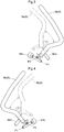
- Fig. 1 is a perspective view showing the grass mowing machine.
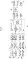
- Fig. 2 is a system diagram showing an electric system and a power system of the grass mowing machine.
- front means the front or forward side in the vehicle body front/rear direction (traveling direction) and the term “rear” means the rear or reverse side in the vehicle body front/rear direction (traveling direction).
- left/right direction or the lateral (transverse) direction refers to the vehicle body transverse direction (vehicle body width direction) orthogonal to the vehicle body front/rear direction.
- the term “upper” or “lower” refers to the positional relationship in the respect of the perpendicular (vertical) direction of the vehicle body, indicating a ground clearance (height).
- the grass mowing machine includes a vehicle body 4 and this vehicle body 4 is supported via front wheels 2 and rear wheels 3.
- the front wheels 2 are caster wheels including a left front wheel 2a and a right front wheel 2b.
- the rear wheels 3 are drive wheels including a left rear wheel 3a and a right rear wheel 3b.
- a battery 24 is disposed at a rear portion of the vehicle body 4.
- a driver's seat 11 is disposed at a rear portion of the vehicle body 4.
- a ROPS frame 12 is disposed.
- a mower unit 13 is suspended from the vehicle body 4 via a lift link mechanism to be liftable up/down.
- a floor plate serving as a footrest for the driver.
- a left maneuvering lever 8a and a right maneuvering lever 8b are an example of a "drive wheel operation unit 8".
- an electric operational panel 18 is provided on the right side of the driver's seat 11 and this electric operational panel 18 includes switching buttons, switching levers, etc. of the electric system.
- a mower operational tool 15 The driver will operate this mower operational tool 15 to effect ON/OFF operations of the mower unit 13.
- the left rear wheel 3a and the right rear wheel 3b as "drive wheels” receive driving power from a pair of left and right drive units and these left and right drive units are controlled in their driving independently of each other.
- the left drive unit includes a left motor 21a and a left speed reduction device 22a.
- the right drive unit includes a right motor 21b and a right speed reduction device 22b.
- the left speed reduction device 22a and the right speed reduction device 22b each incorporates a parking brake 23.
- a power transmission shaft extending from the left motor 21a to the left rear wheel 3a and a power transmission shaft extending from the right motor 21b to the right rear wheel 3b are braked, as a result, the left rear wheel 3a and the right rear wheel 3b are braked.
- a control device 6 includes a drive control unit 6A, a mower control unit 6B, a parking control unit (control unit) 6C.
- the left motor 21a receives power supply from a left power supply section 71 and the left motor 21a is rotatably driven.
- the right motor 21b receives power supply from a right power supply section 72 and the right motor 21b is rotatably driven.
- the left power supply section 71 and the right power supply section 72 are constituted of inverters, which are incorporated in an inverter unit 7.
- the mower unit 13 includes three rotary blades 131.
- the rotary blades 131 rely on mower motors 130 as their driving sources.
- the mower motors 130 Based on a control signal from the mower control unit 6B, the mower motors 130 receive power supply from the mower power supply section 73, whereby the mower motors 130 are rotatably driven.
- the mower power supply section 73 too is constituted of an inverter, which is incorporated in the inverter unit 7.
- the straight traveling state is realized by forwardly driving the left rear wheel 3a and the right rear wheel 3b at an equal speed or reversely driving the left rear wheel 3a and the right rear wheel 3b at an equal speed.
- the gentle turning state is realized by forwardly driving the left rear wheel 3a and the right rear wheel 3b at different speeds or reversely driving the left rear wheel 3a and the right rear wheel 3b at different speeds.
- the pivot turning state is realized by stopping one of the left rear wheel 3a and the right rear wheel 3b and driving the other forwardly or reversely.
- the spin turning state is realized by driving one of the left rear wheel 3a and the right rear wheel 3b forwardly and driving the other reversely.
- the left maneuvering lever 8a and the right maneuvering lever 8b are capable of displacements in the front/rear direction, namely, pivotal displacements about a first axis P1.
- the former half portion of this front/rear direction displacement is used for adjustment of vehicle body forward traveling speed and the latter half portion of this front/rear direction displacement is used for adjustment of vehicle body reverse traveling speed, and its intermediate position is the neutral position in the speed change.
- the left maneuvering lever 8a and the right maneuvering lever 8b are capable, at their intermediate positions, of displacements in the lateral direction, namely, pivotal displacements about a second axis P2.
- the terminal position of this lateral displacement becomes the parking position.
- a displacement amount (a pivot angle) in the front/rear direction of the left maneuvering lever 8a is detected by a left steering angle detection sensor 91a.
- a displacement amount (a pivot angle) in the front/rear direction of the right maneuvering lever 8b is detected by a right steering angle detection sensor 91b.
- the terminal position of the lateral displacement of the left maneuvering lever 8a is detected by a left parking switch 92a.
- the terminal position of the lateral displacement of the right maneuvering lever 8b is detected by a right parking switch 92b.
- the left parking switch 92a and the right parking switch 92b function respectively as a "position detector" for detecting a parking position of the drive wheel operation unit 8 (the left maneuvering lever 8a and the right maneuvering lever 8b).
- a rotational speed of the left rear wheel 3a namely, a rotational speed of the left motor 21a
- a rotational speed of the right rear wheel 3b namely, a rotational speed of the right motor 21b
- the left rotation detection sensor 90a functions as a "rotation detector” for detecting a rotational speed of the left motor 21a and a rotational speed of the left rear wheel 3a
- the right rotation detection sensor 90b functions as a "rotation detector” for detecting a rotational speed of the right motor 21b and a rotational speed of the right rear wheel 3b.
- respective dedicated rotation detectors may be provided.
- the control device 6 is constituted of a CPU as the core component thereof and includes the drive control unit 6A, the mower control unit 6B, and the parking control unit 6C. Rear wheel control signals are generated based on operational amounts of the left maneuvering lever 8a and the right maneuvering lever 8b, respectively.
- the drive control unit 6A provides rear wheel control signals to the left power supply section 71 and the right power supply section 72, thus controlling driving of the left motor 21a and the right motor 21b.
- the mower control unit 6B generates a control signal based on a detection signal from the mower sensor 93 and provides this control signal to the mower power supply section 73, thus controlling driving of the rotary blades 131.
- Fig. 5 shows a functional block diagram of the parking control unit 6C.
- This parking control unit 6C inputs a left parking ON signal, a right parking ON signal, a left rotation signal and a right rotation signal.
- the left parking ON signal is outputted from the left parking switch 92a in response to an operation of the left maneuvering lever 8a to the parking position.
- the right parking ON signal is outputted from the right parking switch 92b in response to an operation of the right maneuvering lever 8b to the parking position.
- the left rotation signal is a signal outputted from the left rotation detection sensor 90a and represents a rotational speed of the left rear wheel 3a or the left motor 21a.
- the right rotation signal is a signal outputted from the right rotation detection sensor 90b and represents a rotational speed of the right rear wheel 3b or the right motor 21b.
- a deceleration instruction, a stop instruction and a parking signal are outputted.
- the deceleration instruction and/or the stop instruction are (is) provided to the drive control unit 6A, whereby one or both of the left motor 21a and the right motor 21b will be stopped or decelerated.
- the parking brake 23 is activated, whereby the left rear wheel 3a and the right rear wheel 3b are braked.
- the parking control unit 6C includes a parking determination section 61, a control signal outputting section 62 and a time management section 63.
- the parking determination section 61 determines that a predetermined state is being detected and provides a parking request to the control signal outputting section 62.
- the control signal outputting section 62 in response to this parking request, provides a parking signal to the parking brake 23 and will render the parking brake 23 into an operative state.
- the input of the parking ON signal means at least one input of the left parking ON signal and the right parking ON signal.
- the input of the parking ON signal may mean inputs of both the left parking ON signal and the right parking ON signal.
- the predetermined state can be a case where both the left rotation signal and the right rotation signal indicate rotational speeds between the zero rotation and the predetermined rotational speed while the parking ON signal is input.
- the parking determination section 61 will determine that the predetermined state is not detected, thus not providing any parking request to the control signal outputting section 62.
- the parking determination section 61 will provide a rotation suppressing request to the control signal outputting section 62 in order to realize the predetermined state. Then, in response to such rotation suppressing request, the control signal outputting section 62 will provide a deceleration instruction or a stop instruction to the drive control unit 6A.
- Such stop instruction to the motor is a zero speed instruction, which causes the motor to stop and causes also the motor to generate a torque to maintain its stopped state. In order to cause a rotating motor to stop, this involves deceleration.
- the deceleration instruction may be inclusive of a stop instruction.
- the time management section 63 determines whether a period lapsed with no detection of the predetermined state exceeds a predetermined period (a threshold value). If this predetermined period is exceeded, the time management section 63 will request to the parking determination section 61 that a parking instruction will be forcibly provided to the control signal outputting section 62. In response to this request, the parking determination section 61 will provide a forcible parking request to the control signal outputting section 62. Then, in response to this forcible parking request, the control signal outputting section 62 will output a forcible parking signal to the parking brake 23 and will render the parking brake 23 into the operative state.
- a predetermined period a threshold value
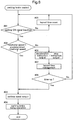
- a parking control routine executed by the parking control unit 6C configured as described above is shown in the flowchart of Fig. 6 .
- this parking control routine firstly, the process checks whether a parking ON signal is inputted or not (step #01). If the parking ON signal is inputted (YES branching at step #01), the process proceeds to check whether either one of the left rotation signal and the right rotation signal indicates a rotational speed between the zero rotation and the predetermined rotational speed or not, namely, whether the predetermined state is being detected or not (step #02). If the predetermined state is detected (YES branching at step #02) then, a parking signal is outputted to the drive control unit 6A (step #03).
- step #04 the parking control unit 6C will render the parking brake 23 into the operative state.
- step #01 if it is determined that no parking ON signal is inputted (NO branching at step #01), then, the process will return to step #01. In this, however, the time management section 63 is currently executing the lapsed time processing, this processing will be reset (step #05).
- step #06 By checking at step #02, if it is determined that the predetermined state is not detected (NO branching at step #02), then, a deceleration instruction or a stop instruction will be outputted to stop the rear wheels 3 (step #06). Further, the lapsed time processing by the time management section 63 is effected (step #07).
- the initial lapsed time processing in the activated parking brake control routine is a timer start. In the lapsed time management subsequent thereto (step #07), the process makes comparison between a lapsed period measured by a timer and a set threshold value.
- step #08 if the lapsed period exceeds the threshold value (time-up) (YES branching ate step #08), the process will branch to step #03 to output a parking signal, so that the parking brake 23 will be rendered into the operative state (step #04). If the lapsed period falls below the threshold value (NO branching at step #08), the process will branch to step #01 to repeat the above-described steps.
- the traveling vehicle may be for instance a multiple-purpose vehicle, a snow plowing vehicle, an agricultural work vehicle, etc., to which the present invention can also be applied.
- variable speed electric motors were employed as the driving sections.
- HST's that are of the hydraulic type and that allow stepless speed changes.
- the inverter control will be replaced by hydraulic control.
- adjustments of swash plates as speed change operations will be effected based on control signals from the drive control unit 6A and the parking brake control will be effected by the parking control unit 6C.
- the drive wheel operation unit 8 was constituted of the pivotal type left maneuvering lever 8a and right maneuvering lever 8b. Instead, the unit may be constituted of a steering wheel. In that case, the parking position will be detected by an operation of switch or the like provided on the steering wheel or in its surrounding.
- the present invention is applicable to a traveling vehicle configured such that a parking brake is operated by an operation of a drive wheel operation unit.
Landscapes
- Engineering & Computer Science (AREA)
- Transportation (AREA)
- Mechanical Engineering (AREA)
- Chemical & Material Sciences (AREA)
- Combustion & Propulsion (AREA)
- Automation & Control Theory (AREA)
- Life Sciences & Earth Sciences (AREA)
- Environmental Sciences (AREA)
- Braking Elements And Transmission Devices (AREA)
- Electric Propulsion And Braking For Vehicles (AREA)
- Guiding Agricultural Machines (AREA)
- Non-Deflectable Wheels, Steering Of Trailers, Or Other Steering (AREA)
- Regulating Braking Force (AREA)
- Mechanical Control Devices (AREA)
Abstract
Description
- A grass mowing machine according to
U.S. Patent No. 6434917 includes a pair of left and right maneuvering levers for adjusting driving speeds and driving directions of a pair of left and right drive wheels, an axial piston variable displacement pump and a hydraulic wheel motor which are operated based on operations of the maneuvering levers, and a parking brake. In response to movements of the maneuvering levers in the front/rear direction, a swash plate of the axial piston variable displacement pump is moved to/ between a forward traveling position, a neutral position and a reverse traveling position. The maneuvering levers are laterally displaceable at their neutral positions. As this lateral displacement of the maneuvering lever is transmitted via a link mechanism to the parking blade, the parking brake is activated. In the case of a grass mowing machine according toU.S. Patent No. 7686108 , in order to determine a forward traveling speed and a reverse traveling speed, a pair of left and right maneuvering levers are movable in the front/rear direction. And, as the maneuvering levers are moved laterally at the neutral position in the front/rear direction, a brake switch is turned ON, whereby a parking brake is activated. - With the grass mowing machines disclosed in
U.S. Patent No. 6434917 andU.S. Patent No. 7686108 , by laterally moving the maneuvering lever from the neutral position, the parking brake is activated. However, even when the maneuvering lever has been moved from a traveling position to the neutral position, this does not necessarily bring the machine body to the stopped state immediately. If the parking brake is activated when the machine body is not at the stopped state, a stopping shock will occur to give discomfort to the driver. The object of the present invention is to provide a work vehicle having a parking brake control arrangement that does not give discomfort to the driver. - According to the present invention, there is provided a traveling vehicle as defined in
claim 1, comprising: - a pair of left and right drive wheels;
- a drive unit for providing driving force to the drive wheels;
- a drive wheel operation unit having a forward speed position, a neutral position, a reverse speed position and a parking position;
- a position detector for detecting the parking position of the drive wheel operation unit;
- a parking brake configured to brake the drive wheels under an operative state thereof
- a rotation detector for detecting a predetermined state from a stopped state to a predetermined rotational speed of the drive wheels; and
- a control unit configured to render the parking brake into the operative state on a condition including detection of the parking position by the position detector and detection of the predetermined state by the rotation detector.
- With the above-described arrangement, in order to allow the parking brake to be rendered into the operative state, this requires not only detection of the parking position by the position detector, but also the condition of the drive wheels being under the stopped state or the rotational speeds of the drive wheels being under the predetermined rotational speed. Namely, even if the drive wheel operation unit is located at the parking position, if rotational speeds of the drive wheels exceed the predetermined rotational speed, the parking brake will not be rendered into the operative state. Thus, the present invention does not give the driver the shock due to sudden stop from a traveling state.
- According to one preferred embodiment:
the drive wheel operation unit is displaceable by a linear operation to/among the forward speed position, the neutral position and the reverse speed position and is displaceable to the parking position while maintaining the neutral position. - With the above-described arrangement, in a traveling situation in which forward traveling operations and reverse traveling operations are repeatedly carried out in alternation across the neutral position, the parking brake is not rendered into the operable state unless the drive wheel operation unit is displaced to the parking position. Thus, the forward traveling operations and the reverse traveling operations can be carried out in a smooth manner. Further, since the arrangement causes the driver to active the parking brake with awareness different from awareness exerted when switching the traveling speed or traveling direction, inadvertent operation of the parking brake can be suppressed.
- According to a preferred embodiment of the present invention:
if the rotation detector detects a rotational speed exceeding the predetermined rotational speed at the time of detection of the parking position by the position detector, the control unit provides a deceleration instruction or a stop instruction to the drive unit. - Even if the driver displaces the drive wheel operation unit to the parking position in order to activate the parking brake, if the rotational speed of the drive wheel exceeds the predetermined rotational speed, the parking brake will be prevented from being rendered into the operative state. Advantageously, in order to allow the parking brake to be activated in such situation as above, the drive unit will automatically effect a deceleration control or stop control to reduce the rotational speed of the drive wheel to a speed lower than the predetermined rotational speed.
- According to a preferred embodiment of the present invention:
- the drive unit comprises a motor: and
- the control unit provides, as the stop instruction, a zero speed instruction to generate a torque in the motor.
- In case the drive unit comprises a motor, for allowing smooth deceleration or stopping of the drive wheels, the stationary torque of the motor can be effectively utilized.
- According to one preferred embodiment of the present invention:
the drive wheel operation unit forcibly renders the parking brake into the operative state if the detection of the parking position by the position detector and the detection of a rotational speed exceeding the predetermined rotational speed by the rotation detector have continued for a predetermined period. - Even if the driver is trying to activate the parking brake, the parking brake will not be activated if the rotational speed of the drive wheel exceeds the predetermined rotational speed. Too long continuation of such situation is not desirable for driving operation.
- According to a still further preferred embodiment of the present invention:
- the drive wheel operation unit comprises a pair of left and right maneuvering levers operable independently to the forward speed position, the neutral position and the reverse speed position; and
- the control unit renders the parking brake into the operative state if the position detector detects the parking positions of both the left maneuvering lever and the right maneuvering lever and the rotation detector detects a rotational speed exceeding the predetermined rotational speed.
- According to a still further preferred embodiment of the present invention:
- the drive wheel operation unit comprises a pair of left and right maneuvering levers operable independently to the forward speed position, the neutral position and the reverse speed position; and
- the control unit renders the parking brake into the operative state if the position detector detects the parking position of either one of the left maneuvering lever and the right maneuvering lever and the rotation detector detects a rotational speed exceeding the predetermined rotational speed.
- In the case of a traveling vehicle such as a zero-turn mower, the vehicle employs the drive wheel operation unit comprised of a pair of left and right maneuvering levers operable independently to the forward speed position, the neutral position and the reverse speed position. With such drive wheel operation unit, there will occur a first state in which only one of the left and right maneuvering levers is operated to the parking position and a second state in which both the left and right maneuvering levers are operated to the parking position. Therefore, it is possible to select the first state or the second state as the requisite condition for rendering the parking brake into the operative state.
-
-
Fig. 1 is a perspective view showing a traveling vehicle, -
Fig. 2 is a system diagram showing an electric system and power system of the traveling vehicle, -
Fig. 3 is a perspective view showing a maneuvering lever at a forward traveling position, -
Fig. 4 is a perspective view showing the maneuvering lever at a parking position, -
Fig. 5 is a functional block diagram showing functions of a control unit, and -
Fig. 6 is a flowchart of parking brake control. - A riding electric grass mowing machine (to be referred to simply as "grass mowing machine" hereafter) disclosed in this embodiment is an example of a "traveling vehicle". While the disclosed embodiment is a riding electric grass mowing machine, the claimed traveling vehicle is not limited to such grass mowing machine.
Fig. 1 is a perspective view showing the grass mowing machine.Fig. 2 is a system diagram showing an electric system and a power system of the grass mowing machine. Incidentally, in this detailed disclosure, unless explicitly indicated otherwise, the term "front" means the front or forward side in the vehicle body front/rear direction (traveling direction) and the term "rear" means the rear or reverse side in the vehicle body front/rear direction (traveling direction). Further, the left/right direction or the lateral (transverse) direction refers to the vehicle body transverse direction (vehicle body width direction) orthogonal to the vehicle body front/rear direction. Also, the term "upper" or "lower" refers to the positional relationship in the respect of the perpendicular (vertical) direction of the vehicle body, indicating a ground clearance (height). - As shown in
Fig. 1 andFig. 2 , the grass mowing machine includes avehicle body 4 and thisvehicle body 4 is supported viafront wheels 2 andrear wheels 3. Thefront wheels 2 are caster wheels including a leftfront wheel 2a and a rightfront wheel 2b. Therear wheels 3 are drive wheels including a leftrear wheel 3a and a rightrear wheel 3b. At a rear portion of thevehicle body 4, abattery 24 is disposed. Forwardly of thebattery 24, a driver'sseat 11 is disposed. Rearwardly of the driver'sseat 11, aROPS frame 12 is disposed. In the space between thefront wheels 2 and therear wheels 3 and under thevehicle body 4, amower unit 13 is suspended from thevehicle body 4 via a lift link mechanism to be liftable up/down. - Forwardly of the driver's
seat 11, a there is provided a floor plate serving as a footrest for the driver. On both sides of the driver'sseat 11, there are disposed aleft maneuvering lever 8a and aright maneuvering lever 8b. Theleft maneuvering lever 8a and theright maneuvering lever 8b are an example of a "drivewheel operation unit 8". On the right side of the driver'sseat 11, an electricoperational panel 18 is provided and this electricoperational panel 18 includes switching buttons, switching levers, etc. of the electric system. On the left side of the driver'sseat 11, there is provided a moweroperational tool 15. The driver will operate this moweroperational tool 15 to effect ON/OFF operations of themower unit 13. - As shown in
Fig. 2 , the leftrear wheel 3a and the rightrear wheel 3b as "drive wheels" receive driving power from a pair of left and right drive units and these left and right drive units are controlled in their driving independently of each other. The left drive unit includes aleft motor 21a and a leftspeed reduction device 22a. The right drive unit includes aright motor 21b and a rightspeed reduction device 22b. The leftspeed reduction device 22a and the rightspeed reduction device 22b each incorporates aparking brake 23. With activations of theparking brake 23, a power transmission shaft extending from theleft motor 21a to the leftrear wheel 3a and a power transmission shaft extending from theright motor 21b to the rightrear wheel 3b are braked, as a result, the leftrear wheel 3a and the rightrear wheel 3b are braked. - A
control device 6 includes adrive control unit 6A, amower control unit 6B, a parking control unit (control unit) 6C. Based on a left rear wheel control signal from thedrive control unit 6A, theleft motor 21a receives power supply from a leftpower supply section 71 and theleft motor 21a is rotatably driven. Based on a right rear wheel control signal from thedrive control unit 6A, theright motor 21b receives power supply from a rightpower supply section 72 and theright motor 21b is rotatably driven. The leftpower supply section 71 and the rightpower supply section 72 are constituted of inverters, which are incorporated in aninverter unit 7. - The
mower unit 13 includes threerotary blades 131. Therotary blades 131 rely onmower motors 130 as their driving sources. Based on a control signal from themower control unit 6B, themower motors 130 receive power supply from the mowerpower supply section 73, whereby themower motors 130 are rotatably driven. The mowerpower supply section 73 too is constituted of an inverter, which is incorporated in theinverter unit 7. - With this grass mowing machine, based on a difference between rotational speeds of the left
rear wheel 3a and the rightrear wheel 3b, a direction change (a turn) of thevehicle body 4 is effected. Speed changes of theleft motor 21a and theright motor 21b are effected based on pivotal operations of theleft maneuvering lever 8a and theright maneuvering lever 8b respectively. In a linear (straight) operational path of theleft maneuvering lever 8a in the front/rear direction, there are set a forward speed position, a neutral position and reverse speed position. In a linear (straight) operational path of theright maneuvering lever 8b in the front/rear direction, there are set a forward speed position, a neutral position and reverse speed position. Namely, when a user operates theleft maneuvering lever 8a and theright maneuvering lever 8b, a straight traveling state, a gentle turning state, a pivot turning state and a spin turning state will be realized respectively. For instance, the straight traveling state is realized by forwardly driving the leftrear wheel 3a and the rightrear wheel 3b at an equal speed or reversely driving the leftrear wheel 3a and the rightrear wheel 3b at an equal speed. The gentle turning state is realized by forwardly driving the leftrear wheel 3a and the rightrear wheel 3b at different speeds or reversely driving the leftrear wheel 3a and the rightrear wheel 3b at different speeds. The pivot turning state is realized by stopping one of the leftrear wheel 3a and the rightrear wheel 3b and driving the other forwardly or reversely. The spin turning state is realized by driving one of the leftrear wheel 3a and the rightrear wheel 3b forwardly and driving the other reversely. - As shown in
Fig. 3 and Fig. 4 , theleft maneuvering lever 8a and theright maneuvering lever 8b are capable of displacements in the front/rear direction, namely, pivotal displacements about a first axis P1. The former half portion of this front/rear direction displacement is used for adjustment of vehicle body forward traveling speed and the latter half portion of this front/rear direction displacement is used for adjustment of vehicle body reverse traveling speed, and its intermediate position is the neutral position in the speed change. Further, theleft maneuvering lever 8a and theright maneuvering lever 8b are capable, at their intermediate positions, of displacements in the lateral direction, namely, pivotal displacements about a second axis P2. The terminal position of this lateral displacement becomes the parking position. When theparking brake 23 is activated by an operation of the drivewheel operation unit 8, reliable stopped state of thevehicle body 4 is created. - A displacement amount (a pivot angle) in the front/rear direction of the
left maneuvering lever 8a is detected by a left steeringangle detection sensor 91a. A displacement amount (a pivot angle) in the front/rear direction of theright maneuvering lever 8b is detected by a right steeringangle detection sensor 91b. Further, the terminal position of the lateral displacement of theleft maneuvering lever 8a is detected by aleft parking switch 92a. And, the terminal position of the lateral displacement of theright maneuvering lever 8b is detected by aright parking switch 92b. Thus, theleft parking switch 92a and theright parking switch 92b function respectively as a "position detector" for detecting a parking position of the drive wheel operation unit 8 (theleft maneuvering lever 8a and theright maneuvering lever 8b). An operation of the moweroperational tool 15 is detected by amower sensor 93. Further, a rotational speed of the leftrear wheel 3a, namely, a rotational speed of theleft motor 21a, is detected by a leftrotation detection sensor 90a, and a rotational speed of the rightrear wheel 3b, namely, a rotational speed of theright motor 21b, is detected by a rightrotation detection sensor 90b. Thus, the leftrotation detection sensor 90a functions as a "rotation detector" for detecting a rotational speed of theleft motor 21a and a rotational speed of the leftrear wheel 3a. Further, the rightrotation detection sensor 90b functions as a "rotation detector" for detecting a rotational speed of theright motor 21b and a rotational speed of the rightrear wheel 3b. Needless to say, respective dedicated rotation detectors may be provided. - The
control device 6 is constituted of a CPU as the core component thereof and includes thedrive control unit 6A, themower control unit 6B, and theparking control unit 6C. Rear wheel control signals are generated based on operational amounts of theleft maneuvering lever 8a and theright maneuvering lever 8b, respectively. Thedrive control unit 6A provides rear wheel control signals to the leftpower supply section 71 and the rightpower supply section 72, thus controlling driving of theleft motor 21a and theright motor 21b. Themower control unit 6B generates a control signal based on a detection signal from themower sensor 93 and provides this control signal to the mowerpower supply section 73, thus controlling driving of therotary blades 131. -
Fig. 5 shows a functional block diagram of theparking control unit 6C. Thisparking control unit 6C inputs a left parking ON signal, a right parking ON signal, a left rotation signal and a right rotation signal. The left parking ON signal is outputted from theleft parking switch 92a in response to an operation of theleft maneuvering lever 8a to the parking position. The right parking ON signal is outputted from theright parking switch 92b in response to an operation of theright maneuvering lever 8b to the parking position. The left rotation signal is a signal outputted from the leftrotation detection sensor 90a and represents a rotational speed of the leftrear wheel 3a or theleft motor 21a. The right rotation signal is a signal outputted from the rightrotation detection sensor 90b and represents a rotational speed of the rightrear wheel 3b or theright motor 21b. - From the
parking control unit 6C, a deceleration instruction, a stop instruction and a parking signal are outputted. The deceleration instruction and/or the stop instruction are (is) provided to thedrive control unit 6A, whereby one or both of theleft motor 21a and theright motor 21b will be stopped or decelerated. In response to the parking signal, theparking brake 23 is activated, whereby the leftrear wheel 3a and the rightrear wheel 3b are braked. - The
parking control unit 6C includes aparking determination section 61, a controlsignal outputting section 62 and atime management section 63. When the parking ON signal is inputted, if either the left rotation signal or the right rotation signal indicates a rotational speed between the zero rotation (stopped state of the rear wheels 3) and a predetermined rotational speed, theparking determination section 61 determines that a predetermined state is being detected and provides a parking request to the controlsignal outputting section 62. Then, the controlsignal outputting section 62, in response to this parking request, provides a parking signal to theparking brake 23 and will render theparking brake 23 into an operative state. In this embodiment, the input of the parking ON signal means at least one input of the left parking ON signal and the right parking ON signal. In a further embodiment, the input of the parking ON signal may mean inputs of both the left parking ON signal and the right parking ON signal. Further, regarding the condition of the predetermined state, the predetermined state can be a case where both the left rotation signal and the right rotation signal indicate rotational speeds between the zero rotation and the predetermined rotational speed while the parking ON signal is input. - Namely, even when the parking ON signal is being inputted, if either one of the left rotation signal and the right rotation signal indicates a rotational speed exceeding the above-described predetermined rotational speed, the
parking determination section 61 will determine that the predetermined state is not detected, thus not providing any parking request to the controlsignal outputting section 62. - Moreover, even when the parking ON signal is being inputted, if either one of the left rotation signal and the right rotation signal indicates a rotational speed exceeding the predetermined rotational speed, the
parking determination section 61 will provide a rotation suppressing request to the controlsignal outputting section 62 in order to realize the predetermined state. Then, in response to such rotation suppressing request, the controlsignal outputting section 62 will provide a deceleration instruction or a stop instruction to thedrive control unit 6A. Such stop instruction to the motor is a zero speed instruction, which causes the motor to stop and causes also the motor to generate a torque to maintain its stopped state. In order to cause a rotating motor to stop, this involves deceleration. Thus, here, the deceleration instruction may be inclusive of a stop instruction. - Under the state of the parking ON signal being inputted, the
time management section 63 determines whether a period lapsed with no detection of the predetermined state exceeds a predetermined period (a threshold value). If this predetermined period is exceeded, thetime management section 63 will request to theparking determination section 61 that a parking instruction will be forcibly provided to the controlsignal outputting section 62. In response to this request, theparking determination section 61 will provide a forcible parking request to the controlsignal outputting section 62. Then, in response to this forcible parking request, the controlsignal outputting section 62 will output a forcible parking signal to theparking brake 23 and will render theparking brake 23 into the operative state. - One example of a parking control routine executed by the
parking control unit 6C configured as described above is shown in the flowchart ofFig. 6 . In this parking control routine, firstly, the process checks whether a parking ON signal is inputted or not (step #01). If the parking ON signal is inputted (YES branching at step #01), the process proceeds to check whether either one of the left rotation signal and the right rotation signal indicates a rotational speed between the zero rotation and the predetermined rotational speed or not, namely, whether the predetermined state is being detected or not (step #02). If the predetermined state is detected (YES branching at step #02) then, a parking signal is outputted to thedrive control unit 6A (step #03). Then, theparking control unit 6C will render theparking brake 23 into the operative state (step #04). By checking atstep # 01, if it is determined that no parking ON signal is inputted (NO branching at step #01), then, the process will return tostep # 01. In this, however, thetime management section 63 is currently executing the lapsed time processing, this processing will be reset (step #05). - By checking at
step # 02, if it is determined that the predetermined state is not detected (NO branching at step #02), then, a deceleration instruction or a stop instruction will be outputted to stop the rear wheels 3 (step #06). Further, the lapsed time processing by thetime management section 63 is effected (step #07). The initial lapsed time processing in the activated parking brake control routine is a timer start. In the lapsed time management subsequent thereto (step #07), the process makes comparison between a lapsed period measured by a timer and a set threshold value. In this comparison, if the lapsed period exceeds the threshold value (time-up) (YES branching ate step #08), the process will branch to step #03 to output a parking signal, so that theparking brake 23 will be rendered into the operative state (step #04). If the lapsed period falls below the threshold value (NO branching at step #08), the process will branch to step #01 to repeat the above-described steps. - In the foregoing embodiment, explanation was made with citing a grass mowing machine as an example of the "traveling vehicle". The traveling vehicle may be for instance a multiple-purpose vehicle, a snow plowing vehicle, an agricultural work vehicle, etc., to which the present invention can also be applied.
- In the foregoing embodiment, variable speed electric motors were employed as the driving sections. In place of this, it is also possible to employ a pair of left and right HST's that are of the hydraulic type and that allow stepless speed changes. With such HST's, the inverter control will be replaced by hydraulic control. And, adjustments of swash plates as speed change operations will be effected based on control signals from the
drive control unit 6A and the parking brake control will be effected by theparking control unit 6C. - In the foregoing embodiment, the drive
wheel operation unit 8 was constituted of the pivotal type leftmaneuvering lever 8a andright maneuvering lever 8b. Instead, the unit may be constituted of a steering wheel. In that case, the parking position will be detected by an operation of switch or the like provided on the steering wheel or in its surrounding. - The present invention is applicable to a traveling vehicle configured such that a parking brake is operated by an operation of a drive wheel operation unit.
- Incidentally, the arrangements disclosed in the above-described embodiment (including the further embodiments, applicable to the following also) may be used in any combination with arrangements disclosed in the other embodiment, unless contradiction results from such combination, Further, the embodiments disclosed in this detailed disclosure are only exemplary, and the present invention is not limited thereto, but various changes and modifications thereof will be possible within a range not departing from the scope of the present invention.
Claims (7)
- A traveling vehicle comprising:a pair of left and right drive wheels (3);a drive unit (21a, 22a, 21b, 22b) configured to provide driving force to the drive wheels (3);a drive wheel operation unit (8) having a forward speed position, a neutral position, a reverse speed position and a parking position;a position detector (92a, 92b) configured to detect the parking position of the drive wheel operation unit (8);a parking brake (23) configured to brake the drive wheels (3) under an operative state thereof;a rotation detector (90a, 90b) configured to detect a predetermined state when the rotational speed of the drive wheels (3) is from a stopped state to a predetermined rotational speed of the drive wheels (3); anda control unit (6C) configured to render the parking brake (23) into the operative state on a condition including detection of the parking position by the position detector (92a, 92b) and detection of the predetermined state by the rotation detector (90a, 90b).
- The traveling vehicle of claim 1, wherein the drive wheel operation unit (8) is displaceable by a linear operation to/among the forward speed position, the neutral position and the reverse speed position and is displaceable to the parking position while maintaining the neutral position.
- The traveling vehicle of claim 1, wherein the control unit (6C) is configured so that, the rotation detector (90a, 90b) detects a rotational speed exceeding the predetermined rotational speed at the time of detection of the parking position by the position detector (92a, 92b), the control unit (6C) provides a deceleration instruction or a stop instruction to the drive unit (21a, 22a, 21b, 22b).
- The traveling vehicle of claim 3, wherein:the drive unit (21a, 22a, 21b, 22b) comprises a motor (21a, 21b): andthe control unit (6C) is configured to provide, as the stop instruction, a zero speed instruction to generate a torque in the motor (21a, 21b).
- The traveling vehicle of claim 1, wherein the drive wheel operation unit (8) is configured to forcibly render the parking brake (23) into the operative state if the detection of the parking position by the position detector (92a, 92b) and the detection of a rotational speed exceeding the predetermined rotational speed by the rotation detector (90a, 90b) have continued for a predetermined period.
- The traveling vehicle of claim 1, wherein:the drive wheel operation unit (8) comprises a pair of left and right maneuvering levers (8a, 8b) operable independently to the forward speed position, the neutral position, the reverse speed position and the parking position; andthe control unit (6C) is configured to render the parking brake (23) into the operative state if the position detector (92a, 92b) detects the parking positions of both the left maneuvering lever (8a) and the right maneuvering lever (8b) and the rotation detector (90a, 90b) detects a rotational speed exceeding the predetermined rotational speed.
- The traveling vehicle of claim 1, wherein:the drive wheel operation unit (8) comprises a pair of left and right maneuvering levers (8a, 8b) operable independently to the forward speed position, the neutral position, the reverse speed position and the parking position; andthe control unit (6C) is configured to render the parking brake (23) into the operative state if the position detector (92a, 92b) detects the parking position of either one of the left maneuvering lever (8a) and the right maneuvering lever (8b) and the rotation detector (90a, 90b) detects a rotational speed exceeding the predetermined rotational speed.
Applications Claiming Priority (1)
| Application Number | Priority Date | Filing Date | Title |
|---|---|---|---|
| JP2019197140A JP7235641B2 (en) | 2019-10-30 | 2019-10-30 | running vehicle |
Publications (2)
| Publication Number | Publication Date |
|---|---|
| EP3816019A1 true EP3816019A1 (en) | 2021-05-05 |
| EP3816019B1 EP3816019B1 (en) | 2022-06-01 |
Family
ID=70682694
Family Applications (1)
| Application Number | Title | Priority Date | Filing Date |
|---|---|---|---|
| EP20174293.9A Active EP3816019B1 (en) | 2019-10-30 | 2020-05-13 | Traveling vehicle |
Country Status (3)
| Country | Link |
|---|---|
| US (1) | US10974597B1 (en) |
| EP (1) | EP3816019B1 (en) |
| JP (1) | JP7235641B2 (en) |
Cited By (1)
| Publication number | Priority date | Publication date | Assignee | Title |
|---|---|---|---|---|
| EP4681522A1 (en) * | 2024-07-18 | 2026-01-21 | Nanjing Chervon Industry Co., Ltd. | Outdoor traveling device |
Families Citing this family (7)
| Publication number | Priority date | Publication date | Assignee | Title |
|---|---|---|---|---|
| WO2019184983A1 (en) * | 2018-03-28 | 2019-10-03 | 南京德朔实业有限公司 | Riding lawn mower and operation device thereof |
| US12296694B2 (en) | 2021-03-10 | 2025-05-13 | Techtronic Cordless Gp | Lawnmowers |
| CN115703350A (en) * | 2021-08-16 | 2023-02-17 | 余姚市爱优特电机有限公司 | rolling vehicle |
| USD1015381S1 (en) | 2022-02-14 | 2024-02-20 | Techtronic Cordless Gp | Lawn mower |
| USD1014568S1 (en) | 2022-02-14 | 2024-02-13 | Techtronic Cordless Gp | Lawn mower |
| JP7738536B2 (en) * | 2022-09-28 | 2025-09-12 | 株式会社クボタ | Work vehicle |
| US12207591B1 (en) | 2023-07-25 | 2025-01-28 | Yakta Inc. | Parking brake control for ride-on zero-turn work machines |
Citations (2)
| Publication number | Priority date | Publication date | Assignee | Title |
|---|---|---|---|---|
| US6434917B1 (en) | 2001-04-13 | 2002-08-20 | Excel Industries, Inc. | Mower with combined steering and brake levers |
| US7686108B2 (en) | 2007-02-09 | 2010-03-30 | Great Plains Manufacturing, Inc. | Electrically released parking brake for zero turn radius mower |
Family Cites Families (6)
| Publication number | Priority date | Publication date | Assignee | Title |
|---|---|---|---|---|
| US6301864B1 (en) * | 1999-07-22 | 2001-10-16 | Ariens Company | Interlock for lawnmower |
| US6729115B2 (en) * | 2002-04-13 | 2004-05-04 | Excel Industries, Inc. | Mower with combined steering an brake levers |
| JP4725468B2 (en) | 2006-09-15 | 2011-07-13 | トヨタ自動車株式会社 | Electric parking brake system |
| US8240420B1 (en) * | 2008-10-23 | 2012-08-14 | Excel Industries, Inc. | Steering mechanism |
| AU2018354590B2 (en) * | 2017-10-26 | 2020-10-15 | Husqvarna Ab | Lawn care vehicle brake system |
| US10681867B2 (en) * | 2018-03-08 | 2020-06-16 | Deere & Company | Zero turning radius mower park brake system |
-
2019
- 2019-10-30 JP JP2019197140A patent/JP7235641B2/en active Active
-
2020
- 2020-05-13 US US15/930,628 patent/US10974597B1/en active Active
- 2020-05-13 EP EP20174293.9A patent/EP3816019B1/en active Active
Patent Citations (2)
| Publication number | Priority date | Publication date | Assignee | Title |
|---|---|---|---|---|
| US6434917B1 (en) | 2001-04-13 | 2002-08-20 | Excel Industries, Inc. | Mower with combined steering and brake levers |
| US7686108B2 (en) | 2007-02-09 | 2010-03-30 | Great Plains Manufacturing, Inc. | Electrically released parking brake for zero turn radius mower |
Cited By (1)
| Publication number | Priority date | Publication date | Assignee | Title |
|---|---|---|---|---|
| EP4681522A1 (en) * | 2024-07-18 | 2026-01-21 | Nanjing Chervon Industry Co., Ltd. | Outdoor traveling device |
Also Published As
| Publication number | Publication date |
|---|---|
| EP3816019B1 (en) | 2022-06-01 |
| US10974597B1 (en) | 2021-04-13 |
| US20210129668A1 (en) | 2021-05-06 |
| JP7235641B2 (en) | 2023-03-08 |
| JP2021070382A (en) | 2021-05-06 |
Similar Documents
| Publication | Publication Date | Title |
|---|---|---|
| EP3816019B1 (en) | Traveling vehicle | |
| US12268122B2 (en) | Work vehicle and grass mowing machine | |
| EP3807116B1 (en) | Grounds maintenance vehicle with traction and steering control system | |
| JP5530383B2 (en) | Work vehicle | |
| JP7065747B2 (en) | Mower | |
| US20170120755A1 (en) | Electric Work Vehicle | |
| EP3501947B1 (en) | Electrically powered work vehicle | |
| EP2682648B1 (en) | Travel control unit of working vehicle | |
| EP3816020B1 (en) | Traveling vehicle | |
| EP3704931B1 (en) | Traveling vehicle | |
| US7603218B2 (en) | Apparatus and method to provide failsafe deceleration for an agricultural windrower | |
| JP6999517B2 (en) | Driving control device | |
| JP6821128B2 (en) | Work vehicle | |
| JP2008057358A (en) | Work vehicle | |
| JP7109283B2 (en) | travel control device | |
| JP6852257B2 (en) | Work vehicle | |
| JP6142168B2 (en) | Travel control device for work vehicle | |
| JP7675434B2 (en) | Electric Work Vehicle | |
| JPH04110233A (en) | Front wheel drive controller for tractor | |
| JP2007030777A (en) | Deceleration pedal device for work vehicle | |
| JP2000211389A (en) | Turning device for work vehicle |
Legal Events
| Date | Code | Title | Description |
|---|---|---|---|
| PUAI | Public reference made under article 153(3) epc to a published international application that has entered the european phase |
Free format text: ORIGINAL CODE: 0009012 |
|
| STAA | Information on the status of an ep patent application or granted ep patent |
Free format text: STATUS: REQUEST FOR EXAMINATION WAS MADE |
|
| 17P | Request for examination filed |
Effective date: 20200513 |
|
| AK | Designated contracting states |
Kind code of ref document: A1 Designated state(s): AL AT BE BG CH CY CZ DE DK EE ES FI FR GB GR HR HU IE IS IT LI LT LU LV MC MK MT NL NO PL PT RO RS SE SI SK SM TR |
|
| GRAP | Despatch of communication of intention to grant a patent |
Free format text: ORIGINAL CODE: EPIDOSNIGR1 |
|
| STAA | Information on the status of an ep patent application or granted ep patent |
Free format text: STATUS: GRANT OF PATENT IS INTENDED |
|
| RIC1 | Information provided on ipc code assigned before grant |
Ipc: A01D 34/69 20060101ALI20211206BHEP Ipc: B62D 11/04 20060101ALI20211206BHEP Ipc: B62D 11/00 20060101AFI20211206BHEP |
|
| INTG | Intention to grant announced |
Effective date: 20211220 |
|
| GRAS | Grant fee paid |
Free format text: ORIGINAL CODE: EPIDOSNIGR3 |
|
| GRAA | (expected) grant |
Free format text: ORIGINAL CODE: 0009210 |
|
| STAA | Information on the status of an ep patent application or granted ep patent |
Free format text: STATUS: THE PATENT HAS BEEN GRANTED |
|
| AK | Designated contracting states |
Kind code of ref document: B1 Designated state(s): AL AT BE BG CH CY CZ DE DK EE ES FI FR GB GR HR HU IE IS IT LI LT LU LV MC MK MT NL NO PL PT RO RS SE SI SK SM TR |
|
| REG | Reference to a national code |
Ref country code: GB Ref legal event code: FG4D |
|
| REG | Reference to a national code |
Ref country code: AT Ref legal event code: REF Ref document number: 1495216 Country of ref document: AT Kind code of ref document: T Effective date: 20220615 Ref country code: CH Ref legal event code: EP Ref country code: DE Ref legal event code: R096 Ref document number: 602020003339 Country of ref document: DE |
|
| REG | Reference to a national code |
Ref country code: IE Ref legal event code: FG4D |
|
| REG | Reference to a national code |
Ref country code: LT Ref legal event code: MG9D |
|
| REG | Reference to a national code |
Ref country code: NL Ref legal event code: MP Effective date: 20220601 |
|
| PG25 | Lapsed in a contracting state [announced via postgrant information from national office to epo] |
Ref country code: SE Free format text: LAPSE BECAUSE OF FAILURE TO SUBMIT A TRANSLATION OF THE DESCRIPTION OR TO PAY THE FEE WITHIN THE PRESCRIBED TIME-LIMIT Effective date: 20220601 Ref country code: NO Free format text: LAPSE BECAUSE OF FAILURE TO SUBMIT A TRANSLATION OF THE DESCRIPTION OR TO PAY THE FEE WITHIN THE PRESCRIBED TIME-LIMIT Effective date: 20220901 Ref country code: LT Free format text: LAPSE BECAUSE OF FAILURE TO SUBMIT A TRANSLATION OF THE DESCRIPTION OR TO PAY THE FEE WITHIN THE PRESCRIBED TIME-LIMIT Effective date: 20220601 Ref country code: HR Free format text: LAPSE BECAUSE OF FAILURE TO SUBMIT A TRANSLATION OF THE DESCRIPTION OR TO PAY THE FEE WITHIN THE PRESCRIBED TIME-LIMIT Effective date: 20220601 Ref country code: GR Free format text: LAPSE BECAUSE OF FAILURE TO SUBMIT A TRANSLATION OF THE DESCRIPTION OR TO PAY THE FEE WITHIN THE PRESCRIBED TIME-LIMIT Effective date: 20220902 Ref country code: FI Free format text: LAPSE BECAUSE OF FAILURE TO SUBMIT A TRANSLATION OF THE DESCRIPTION OR TO PAY THE FEE WITHIN THE PRESCRIBED TIME-LIMIT Effective date: 20220601 Ref country code: BG Free format text: LAPSE BECAUSE OF FAILURE TO SUBMIT A TRANSLATION OF THE DESCRIPTION OR TO PAY THE FEE WITHIN THE PRESCRIBED TIME-LIMIT Effective date: 20220901 |
|
| REG | Reference to a national code |
Ref country code: AT Ref legal event code: MK05 Ref document number: 1495216 Country of ref document: AT Kind code of ref document: T Effective date: 20220601 |
|
| PG25 | Lapsed in a contracting state [announced via postgrant information from national office to epo] |
Ref country code: RS Free format text: LAPSE BECAUSE OF FAILURE TO SUBMIT A TRANSLATION OF THE DESCRIPTION OR TO PAY THE FEE WITHIN THE PRESCRIBED TIME-LIMIT Effective date: 20220601 Ref country code: PL Free format text: LAPSE BECAUSE OF FAILURE TO SUBMIT A TRANSLATION OF THE DESCRIPTION OR TO PAY THE FEE WITHIN THE PRESCRIBED TIME-LIMIT Effective date: 20220601 Ref country code: LV Free format text: LAPSE BECAUSE OF FAILURE TO SUBMIT A TRANSLATION OF THE DESCRIPTION OR TO PAY THE FEE WITHIN THE PRESCRIBED TIME-LIMIT Effective date: 20220601 |
|
| PG25 | Lapsed in a contracting state [announced via postgrant information from national office to epo] |
Ref country code: NL Free format text: LAPSE BECAUSE OF FAILURE TO SUBMIT A TRANSLATION OF THE DESCRIPTION OR TO PAY THE FEE WITHIN THE PRESCRIBED TIME-LIMIT Effective date: 20220601 |
|
| PG25 | Lapsed in a contracting state [announced via postgrant information from national office to epo] |
Ref country code: SM Free format text: LAPSE BECAUSE OF FAILURE TO SUBMIT A TRANSLATION OF THE DESCRIPTION OR TO PAY THE FEE WITHIN THE PRESCRIBED TIME-LIMIT Effective date: 20220601 Ref country code: SK Free format text: LAPSE BECAUSE OF FAILURE TO SUBMIT A TRANSLATION OF THE DESCRIPTION OR TO PAY THE FEE WITHIN THE PRESCRIBED TIME-LIMIT Effective date: 20220601 Ref country code: RO Free format text: LAPSE BECAUSE OF FAILURE TO SUBMIT A TRANSLATION OF THE DESCRIPTION OR TO PAY THE FEE WITHIN THE PRESCRIBED TIME-LIMIT Effective date: 20220601 Ref country code: PT Free format text: LAPSE BECAUSE OF FAILURE TO SUBMIT A TRANSLATION OF THE DESCRIPTION OR TO PAY THE FEE WITHIN THE PRESCRIBED TIME-LIMIT Effective date: 20221003 Ref country code: ES Free format text: LAPSE BECAUSE OF FAILURE TO SUBMIT A TRANSLATION OF THE DESCRIPTION OR TO PAY THE FEE WITHIN THE PRESCRIBED TIME-LIMIT Effective date: 20220601 Ref country code: EE Free format text: LAPSE BECAUSE OF FAILURE TO SUBMIT A TRANSLATION OF THE DESCRIPTION OR TO PAY THE FEE WITHIN THE PRESCRIBED TIME-LIMIT Effective date: 20220601 Ref country code: CZ Free format text: LAPSE BECAUSE OF FAILURE TO SUBMIT A TRANSLATION OF THE DESCRIPTION OR TO PAY THE FEE WITHIN THE PRESCRIBED TIME-LIMIT Effective date: 20220601 Ref country code: AT Free format text: LAPSE BECAUSE OF FAILURE TO SUBMIT A TRANSLATION OF THE DESCRIPTION OR TO PAY THE FEE WITHIN THE PRESCRIBED TIME-LIMIT Effective date: 20220601 |
|
| PG25 | Lapsed in a contracting state [announced via postgrant information from national office to epo] |
Ref country code: IS Free format text: LAPSE BECAUSE OF FAILURE TO SUBMIT A TRANSLATION OF THE DESCRIPTION OR TO PAY THE FEE WITHIN THE PRESCRIBED TIME-LIMIT Effective date: 20221001 |
|
| REG | Reference to a national code |
Ref country code: DE Ref legal event code: R097 Ref document number: 602020003339 Country of ref document: DE |
|
| REG | Reference to a national code |
Ref country code: DE Ref legal event code: R082 Ref document number: 602020003339 Country of ref document: DE Representative=s name: CBDL PATENTANWAELTE GBR, DE Ref country code: DE Ref legal event code: R082 Ref document number: 602020003339 Country of ref document: DE Representative=s name: CBDL PATENTANWAELTE EGBR, DE |
|
| PG25 | Lapsed in a contracting state [announced via postgrant information from national office to epo] |
Ref country code: AL Free format text: LAPSE BECAUSE OF FAILURE TO SUBMIT A TRANSLATION OF THE DESCRIPTION OR TO PAY THE FEE WITHIN THE PRESCRIBED TIME-LIMIT Effective date: 20220601 |
|
| PLBE | No opposition filed within time limit |
Free format text: ORIGINAL CODE: 0009261 |
|
| STAA | Information on the status of an ep patent application or granted ep patent |
Free format text: STATUS: NO OPPOSITION FILED WITHIN TIME LIMIT |
|
| PG25 | Lapsed in a contracting state [announced via postgrant information from national office to epo] |
Ref country code: DK Free format text: LAPSE BECAUSE OF FAILURE TO SUBMIT A TRANSLATION OF THE DESCRIPTION OR TO PAY THE FEE WITHIN THE PRESCRIBED TIME-LIMIT Effective date: 20220601 |
|
| 26N | No opposition filed |
Effective date: 20230302 |
|
| PG25 | Lapsed in a contracting state [announced via postgrant information from national office to epo] |
Ref country code: SI Free format text: LAPSE BECAUSE OF FAILURE TO SUBMIT A TRANSLATION OF THE DESCRIPTION OR TO PAY THE FEE WITHIN THE PRESCRIBED TIME-LIMIT Effective date: 20220601 |
|
| REG | Reference to a national code |
Ref country code: CH Ref legal event code: PL |
|
| PG25 | Lapsed in a contracting state [announced via postgrant information from national office to epo] |
Ref country code: MC Free format text: LAPSE BECAUSE OF FAILURE TO SUBMIT A TRANSLATION OF THE DESCRIPTION OR TO PAY THE FEE WITHIN THE PRESCRIBED TIME-LIMIT Effective date: 20220601 |
|
| REG | Reference to a national code |
Ref country code: BE Ref legal event code: MM Effective date: 20230531 |
|
| PG25 | Lapsed in a contracting state [announced via postgrant information from national office to epo] |
Ref country code: MC Free format text: LAPSE BECAUSE OF FAILURE TO SUBMIT A TRANSLATION OF THE DESCRIPTION OR TO PAY THE FEE WITHIN THE PRESCRIBED TIME-LIMIT Effective date: 20220601 Ref country code: LU Free format text: LAPSE BECAUSE OF NON-PAYMENT OF DUE FEES Effective date: 20230513 Ref country code: LI Free format text: LAPSE BECAUSE OF NON-PAYMENT OF DUE FEES Effective date: 20230531 Ref country code: IT Free format text: LAPSE BECAUSE OF FAILURE TO SUBMIT A TRANSLATION OF THE DESCRIPTION OR TO PAY THE FEE WITHIN THE PRESCRIBED TIME-LIMIT Effective date: 20220601 Ref country code: CH Free format text: LAPSE BECAUSE OF NON-PAYMENT OF DUE FEES Effective date: 20230531 |
|
| REG | Reference to a national code |
Ref country code: IE Ref legal event code: MM4A |
|
| PG25 | Lapsed in a contracting state [announced via postgrant information from national office to epo] |
Ref country code: IE Free format text: LAPSE BECAUSE OF NON-PAYMENT OF DUE FEES Effective date: 20230513 |
|
| PG25 | Lapsed in a contracting state [announced via postgrant information from national office to epo] |
Ref country code: IE Free format text: LAPSE BECAUSE OF NON-PAYMENT OF DUE FEES Effective date: 20230513 |
|
| PG25 | Lapsed in a contracting state [announced via postgrant information from national office to epo] |
Ref country code: BE Free format text: LAPSE BECAUSE OF NON-PAYMENT OF DUE FEES Effective date: 20230531 |
|
| PG25 | Lapsed in a contracting state [announced via postgrant information from national office to epo] |
Ref country code: BG Free format text: LAPSE BECAUSE OF FAILURE TO SUBMIT A TRANSLATION OF THE DESCRIPTION OR TO PAY THE FEE WITHIN THE PRESCRIBED TIME-LIMIT Effective date: 20220601 |
|
| PG25 | Lapsed in a contracting state [announced via postgrant information from national office to epo] |
Ref country code: BG Free format text: LAPSE BECAUSE OF FAILURE TO SUBMIT A TRANSLATION OF THE DESCRIPTION OR TO PAY THE FEE WITHIN THE PRESCRIBED TIME-LIMIT Effective date: 20220601 |
|
| GBPC | Gb: european patent ceased through non-payment of renewal fee |
Effective date: 20240513 |
|
| PG25 | Lapsed in a contracting state [announced via postgrant information from national office to epo] |
Ref country code: GB Free format text: LAPSE BECAUSE OF NON-PAYMENT OF DUE FEES Effective date: 20240513 |
|
| PGFP | Annual fee paid to national office [announced via postgrant information from national office to epo] |
Ref country code: DE Payment date: 20250402 Year of fee payment: 6 |
|
| PGFP | Annual fee paid to national office [announced via postgrant information from national office to epo] |
Ref country code: FR Payment date: 20250401 Year of fee payment: 6 |
|
| PG25 | Lapsed in a contracting state [announced via postgrant information from national office to epo] |
Ref country code: CY Free format text: LAPSE BECAUSE OF FAILURE TO SUBMIT A TRANSLATION OF THE DESCRIPTION OR TO PAY THE FEE WITHIN THE PRESCRIBED TIME-LIMIT; INVALID AB INITIO Effective date: 20200513 |
|
| PG25 | Lapsed in a contracting state [announced via postgrant information from national office to epo] |
Ref country code: HU Free format text: LAPSE BECAUSE OF FAILURE TO SUBMIT A TRANSLATION OF THE DESCRIPTION OR TO PAY THE FEE WITHIN THE PRESCRIBED TIME-LIMIT; INVALID AB INITIO Effective date: 20200513 |
|
| PG25 | Lapsed in a contracting state [announced via postgrant information from national office to epo] |
Ref country code: TR Free format text: LAPSE BECAUSE OF FAILURE TO SUBMIT A TRANSLATION OF THE DESCRIPTION OR TO PAY THE FEE WITHIN THE PRESCRIBED TIME-LIMIT Effective date: 20220601 |