EP3816013A1 - Detection-region database creating device - Google Patents
Detection-region database creating device Download PDFInfo
- Publication number
- EP3816013A1 EP3816013A1 EP19824624.1A EP19824624A EP3816013A1 EP 3816013 A1 EP3816013 A1 EP 3816013A1 EP 19824624 A EP19824624 A EP 19824624A EP 3816013 A1 EP3816013 A1 EP 3816013A1
- Authority
- EP
- European Patent Office
- Prior art keywords
- detection
- region
- railway vehicle
- image
- database
- Prior art date
- Legal status (The legal status is an assumption and is not a legal conclusion. Google has not performed a legal analysis and makes no representation as to the accuracy of the status listed.)
- Pending
Links
Images




Classifications
-
- B—PERFORMING OPERATIONS; TRANSPORTING
- B61—RAILWAYS
- B61L—GUIDING RAILWAY TRAFFIC; ENSURING THE SAFETY OF RAILWAY TRAFFIC
- B61L23/00—Control, warning or like safety means along the route or between vehicles or trains
- B61L23/04—Control, warning or like safety means along the route or between vehicles or trains for monitoring the mechanical state of the route
- B61L23/041—Obstacle detection
-
- B—PERFORMING OPERATIONS; TRANSPORTING
- B61—RAILWAYS
- B61L—GUIDING RAILWAY TRAFFIC; ENSURING THE SAFETY OF RAILWAY TRAFFIC
- B61L15/00—Indicators provided on the vehicle or train for signalling purposes
- B61L15/009—On-board display devices
-
- B—PERFORMING OPERATIONS; TRANSPORTING
- B61—RAILWAYS
- B61L—GUIDING RAILWAY TRAFFIC; ENSURING THE SAFETY OF RAILWAY TRAFFIC
- B61L23/00—Control, warning or like safety means along the route or between vehicles or trains
- B61L23/04—Control, warning or like safety means along the route or between vehicles or trains for monitoring the mechanical state of the route
-
- B—PERFORMING OPERATIONS; TRANSPORTING
- B61—RAILWAYS
- B61L—GUIDING RAILWAY TRAFFIC; ENSURING THE SAFETY OF RAILWAY TRAFFIC
- B61L25/00—Recording or indicating positions or identities of vehicles or trains or setting of track apparatus
- B61L25/02—Indicating or recording positions or identities of vehicles or trains
- B61L25/025—Absolute localisation, e.g. providing geodetic coordinates
-
- B—PERFORMING OPERATIONS; TRANSPORTING
- B61—RAILWAYS
- B61L—GUIDING RAILWAY TRAFFIC; ENSURING THE SAFETY OF RAILWAY TRAFFIC
- B61L25/00—Recording or indicating positions or identities of vehicles or trains or setting of track apparatus
- B61L25/02—Indicating or recording positions or identities of vehicles or trains
- B61L25/026—Relative localisation, e.g. using odometer
Definitions
- Embodiments of the present invention relate to a detection-region database creating device.
- an object that interrupts the travel of the railway vehicle exists in the route of the railway vehicle.
- the object is referred to as an obstacle.
- equipment to prevent the occurrence of the obstacle or detecting equipment to detect the obstacle has been introduced in a section where the obstacle easily occurs in the route of the railway vehicle due to falling of a passenger or baggage from a platform, or getting stuck of an automobile or a bicycle in a railroad crossing.
- an obstacle detecting technique for detecting the obstacle by using a captured image resulting from the image capture of an area ahead of the railway vehicle by an image capturing device mounted in the railway vehicle has been developed.
- the obstacle is detected from a predetermined detection region in the captured image and it has been necessary to detect with high accuracy the obstacle existing in the route of the railway vehicle by extending the detection region in accordance with the travel position of the railway vehicle.
- a method for creating the detection-region database a method in which the database is created using, for example, an aerial photograph that is obtained by photographing the travel position of the railway vehicle from above, has been developed.
- a detection-region database creating device includes an acquiring module, and a creating module.
- the acquiring module acquires, from a railway vehicle, a captured image obtained by capturing an image in a traveling direction of the railway vehicle by an image capturing device in the railway vehicle, and a travel position of the railway vehicle when the captured image is obtained.
- the creating module creates, on the basis of the captured image and the travel position, a detection-region database that associates a target position with detection-region information representing a three-dimensional shape of the extended region, the target position being a position corresponding to the travel position at which a detection region where an obstacle that interrupts travel of the railway vehicle in the captured image is detected is extended to an extended region outside a rolling stock gauge or a construction gauge of the railway vehicle.
- a safety travelling support system for railway system including a detection-region database creating device according to the present embodiment is described with reference to the drawings.
- FIG. 1 is a diagram illustrating one example of a structure of the safety travelling support system according to the present embodiment.
- the safety travelling support system according to the present embodiment includes a railway vehicle RV and a detection-region database creating device D as illustrated in FIG. 1 .
- the railway vehicle RV and the detection-region database creating device D can communicate various pieces of information with each other through wireless communication or the like.
- the railway vehicle RV includes a sensor 101, an obstacle detection device 102, a recording device 103, a display 104, and a position measuring device 105.
- the sensor 101 is one example of an image capturing device that is provided so as to be able to capture an image in a traveling direction of the railway vehicle RV.
- the obstacle detection device 102 is an obstacle detection device configured to detect an object that interrupts the travel of the railway vehicle RV.
- the object described above is referred to as an obstacle.
- the recording device 103 is a storage that stores therein the result of detecting the obstacle by the obstacle detection device 102.
- the display 104 displays various pieces of information including the captured image resulting from the image capture in the traveling direction of the railway vehicle RV by the sensor 101 and the result of detecting the obstacle by the obstacle detection device 102.
- the position measuring device 105 measures the travel position of the railway vehicle RV.
- the position measuring device 105 measures the travel position of the railway vehicle RV using a rate generator (TG), a global navigation satellite system (GNSS), an acceleration sensor, a gyro sensor, or the like.
- TG rate generator
- GNSS global navigation satellite system
- acceleration sensor a gyro sensor
- the detection-region database creating device D is a personal computer or the like. Specifically, the detection-region database creating device D includes a controller 201, a recording device 202, and a display 203 as illustrated in FIG. 1 .
- the controller 201 controls the entire detection-region database creating device D.
- the controller 201 creates a database that associates a target position with the detection-region information.
- the database described above is referred to as a detection-region database.
- the target position corresponds to the travel position of the railway vehicle RV at which a region where the obstacle is detected in the captured image is extended to an extended region outside the rolling stock gauge or the construction gauge of the railway vehicle RV.
- the region described is referred to as a detection region.
- the detection-region information corresponds to the information representing the three-dimensional shape of the extended region at the target position.
- the recording device 202 stores therein various pieces of information including the captured image obtained by the image capture of the sensor 101 mounted on the railway vehicle RV.
- the display 203 is a liquid crystal display (LCD) or the like, and displays a screen used to create the detection-region database.
- the screen described above is referred to as a database creation screen.
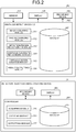
- FIG. 2 is a diagram illustrating one example of a function structure of the obstacle detection device and the controller of the detection-region database creating device for the railway vehicle according to the present embodiment.
- the obstacle detection device 102 in the railway vehicle RV includes an image acquiring module 301, a rail recognizing module 302, a detection-region recognizing module 303, an obstacle candidate recognizing module 304, an obstacle determination module 305, and a result outputting module 306 as illustrated in FIG. 2 .
- the image acquiring module 301, the rail recognizing module 302, the detection-region recognizing module 303, the obstacle candidate recognizing module 304, the obstacle determination module 305, and the result outputting module 306 are partially or entirely implemented by having a processor such as a central processing unit (CPU) in the railway vehicle RV execute software stored in the recording device 103, for example.
- a processor such as a central processing unit (CPU) in the railway vehicle RV execute software stored in the recording device 103, for example.
- the image acquiring module 301, the rail recognizing module 302, the detection-region recognizing module 303, the obstacle candidate recognizing module 304, the obstacle determination module 305, and the result outputting module 306 may be partially or entirely implemented by hardware corresponding to a circuit board such as Large Scale Integration (LSI), Application Specific Integrated Circuit (ASIC), or Field Programmable Integrated Circuit (FPGA).
- LSI Large Scale Integration
- ASIC Application Specific Integrated Circuit
- FPGA Field Programmable Integrated Circuit
- the image acquiring module 301, the rail recognizing module 302, the detection-region recognizing module 303, the obstacle candidate recognizing module 304, the obstacle determination module 305, and the result outputting module 306 may be implemented by cooperation of hardware and software executed by the processor.
- a storage 307 includes a nonvolatile storage medium such as a read only memory (ROM), a flash memory, a hard disk drive (HDD), or an SD card, and a volatile storage medium such as a random access memory (RAM) or a register.
- the storage 307 stores therein various pieces of information including the detection-region database.
- the image acquiring module 301 acquires the captured image resulting from the image capture in the traveling direction of the railway vehicle RV by the sensor 101.
- the rail recognizing module 302 detects the rail where the railway vehicle RV travels from the captured image.
- the detection-region recognizing module 303 sets a three-dimensional detection region for the captured image on the basis of the rail detected by the rail recognizing module 302.
- the detection region corresponds to a three-dimensional region including a defined region that is defined by the rolling stock gauge or the construction gauge of the railway vehicle RV in the captured image.
- the detection-region recognizing module 303 extends the detection region to the extended region. Specifically, the detection-region recognizing module 303 receives in advance the detection-region database from the detection-region database creating device D.
- the detection-region database is a database that associates the target position (for example, kilometrage, or latitude and altitude) with the detection-region information representing the three-dimensional shape of the extended region.
- the detection-region database associates the position of a railroad switch existing in the route of the railway vehicle RV with the route information representing the route of the railway vehicle RV after the railroad switch.
- the position described above is referred to as a switching position, for example kilometrage, or latitude and altitude.
- the detection-region database includes the position of a tunnel existing in the route of the railway vehicle RV.
- the position described above is referred to as a tunnel position, for example kilometrage, or latitude and altitude.
- the detection-region recognizing module 303 specifies the detection-region information associated with the target position that coincides with the travel position of the railway vehicle RV measured by the position measuring device 105 in the detection-region database. Then, on the basis of the specified detection-region information, the detection-region recognizing module 303 extends the detection region so that the detection region can include the extended region at the target position.
- a railroad crossing where a pedestrian, a bicycle, an automobile, or the like crossing the rail may become an obstacle that interrupts the travel of the railway vehicle RV, or a platform from which a passenger or baggage can fall on the rail and may become an obstacle that interrupts the travel of the railway vehicle RV
- a platform from which a passenger or baggage can fall on the rail may become an obstacle that interrupts the travel of the railway vehicle RV
- the detection-region recognizing module 303 sets the detection region for only the route represented by the route information among a plurality of routes after the railroad switch. Thus, it is possible to prevent the object that exists in the route where the railway vehicle RV does not advance from being detected as the obstacle.
- the detection-region recognizing module 303 changes the method of measuring the travel position by the position measuring device 105 or the image capture condition of the sensor 101.
- the detection-region recognizing module 303 changes the method of measuring the travel position by the position measuring device 105 from the measuring method using GNSS to a measuring method using TG, an acceleration sensor, or a gyro sensor.
- the detection-region recognizing module 303 increases the sensitivity of the sensor 101.
- the detection-region recognizing module 303 returns the method of measuring the travel position by the position measuring device 105 to the measuring method using GNSS. In addition, when the travel position measured by the position measuring device 105 coincides with the exit of the tunnel in the detection-region database, the detection-region recognizing module 303 decreases the sensitivity of the sensor 101.
- the obstacle candidate recognizing module 304 extracts objects included in the detection region as candidates for the obstacle (obstacle candidates) on the basis of the captured image having the detection region defined therein.
- the obstacle determination module 305 detects the obstacle from among the obstacle candidates extracted by the obstacle candidate recognizing module 304 on the basis of at least one of the size of the obstacle candidates and motion vectors of the obstacle candidates.
- the object that is more likely to become the obstacle among the objects existing in the detection region can be detected as the obstacle; therefore, the obstacle can be detected with higher accuracy.
- the result outputting module 306 outputs the result of detecting the obstacle by the obstacle determination module 305. Moreover, the result outputting module 306 adds the travel position of the railway vehicle RV, the travel position being measured by the position measuring device 105 when the captured image is obtained by the sensor 101, to the obtained captured image and transmits the obtained data to the detection-region database creating device D.
- the detection-region database creating device D includes an acquiring module 310, a creating module 311, an outputting module 312, and a storage 313.
- the acquiring module 310, the creating module 311, and the outputting module 312 are partially or entirely implemented by having the processor such as a CPU in the detection-region database creating device D execute software stored in the recording device 202.
- the acquiring module 310, the creating module 311, and the outputting module 312 may be partially or entirely implemented by hardware, which is a circuit board such as LSI, ASIC, or FPGA.
- the acquiring module 310, the creating module 311, and the outputting module 312 may be implemented by cooperation of hardware and software executed by the processor.
- the storage 313 includes a nonvolatile storage medium such as a ROM, a flash memory, an HDD, or an SD card, and a volatile storage medium such as a RAM or a register.
- the storage 313 stores therein various pieces of information including the detection-region database.
- the acquiring module 310 acquires from the railway vehicle RV, the captured image and the travel position of the railway vehicle RV when the captured image is obtained. Then, the acquiring module 310 associates the acquired captured image with the travel position of the railway vehicle RV when the captured image is obtained, and stores the associated data in the recording device 202.
- the information may be acquired from the railway vehicle RV offline at the railyard or the station after a predetermined travel, or from the railway vehicle RV in real time through a radio line during the travel.
- the creating module 311 creates the detection-region database on the basis of the captured image and the travel position of the railway vehicle RV that are stored in association with each other in the recording device 202. Then, the creating module 311 stores the created detection-region database in the storage 313.
- the detection-region database can be created on the basis of the information about the target position (for example, the height or width of the platform) that cannot be seen from the image obtained by capturing the travel section of the railway vehicle RV from above (for example, aerial photograph); therefore, the detection-region database can be created that enables the obstacle for the railway vehicle RV to be detected with high accuracy.
- FIG. 3 is a diagram for describing one example of a process for creating the detection-region database by the detection-region database creating device according to the present embodiment.
- the detection-region database associates the target position (for example, kilometrage) with the detection-region information as illustrated in Table 1 below.
- the detection-region information includes a type number, an effective range N1, an internal distance N2, a width N3, a lower distance N4, and a height N5.
- the detection-region information may include positional information of the extended region at the target position.
- the detection-region information may include the positional information representing whether the extended region exists on the right side or the left side in a width direction X (see FIG. 3 ) of the railway vehicle RV on the basis of a rail R where the railway vehicle RV travels.
- the detection-region database may include transmission positional information by associating this transmission positional information with the target position. The transmission positional information can specify the transmission position from which the detection-region database is transmitted to the railway vehicle RV.
- the type number is the number that represents the type of the target position, for example a left platform in the traveling direction of the railway vehicle RV (opposing platform), a right platform in the traveling direction of the railway vehicle RV (island platform), a left crossing gate in the traveling direction of the railway vehicle RV, a right crossing gate in the traveling direction of the railway vehicle RV, a sign, a traffic light, a tunnel, or a railway bridge.
- the detection-region database creating device D stores in the storage 313 or the like, a type database (see Table 2 below) that associates the type number with the type of the target position.
- the creating module 311 causes the display 203 to display the type database so that the type database can be used as a reference.
- the effective range N1 is the depth of an extended region E that exists outside a defined region T (rolling stock gauge T1 or construction gauge T2) or the length of the extended region E to a traveling direction Z of the railway vehicle RV as illustrated in FIG. 3 .
- the internal distance N2 is the distance from an intermediate point between the rails R in the width direction X of the railway vehicle RV to the inner end of the extended region E as illustrated in FIG. 3 .
- the width N3 is the width of the extended region E in the width direction X of the railway vehicle RV as illustrated in FIG. 3 .
- the lower distance N4 is the distance from the rail R to the lower end of the extended region E in a height direction Y of the railway vehicle RV as illustrated in FIG. 3 .
- the height N5 is the height of the extended region E in the height direction Y of the railway vehicle RV as illustrated in FIG. 3 .
- the creating module 311 causes the display 203 to display a screen including the captured image and an entry field.
- the screen described above is referred to as a database creation screen.
- the entry field is the field that displays the target position and the detection-region information that are input by the user of the detection-region database creating device D.
- the user of the detection-region database creating device D can input the target position and the detection-region information while seeing the captured image displayed on the display 203; therefore, the work of creating the detection-region database can be facilitated.
- the creating module 311 creates the detection-region database that associates the target position with the detection-region information that are input using the entry field.
- the creating module 311 detects an image that symbolizes the target position from the captured image by an image recognition process.
- the image described above is referred to as a target position image.
- the creating module 311 detects the fence of the platform, the crossing gate, the dedicated sign, the traffic light, or the like as the target position image from the captured image.
- the creating module 311 detects, as the target position image, the image that symbolizes the target position existing a predetermined distance (for example, 30 m) ahead of the end of the railway vehicle RV to the traveling direction Z of the railway vehicle RV.
- the creating module 311 causes the display 203 to display the detection information expressing that the target position image has been detected (for example, a message expressing that the target position image has been detected).
- the detection-region database creating device D creates the detection-region database while seeing the captured image displayed on the display 203, the user can easily recognize that the target position image is included in the captured image; therefore, the work of creating the detection-region database can be facilitated.
- the creating module 311 causes the display 203 to display a preview image in which a detection-region image corresponding to the image representing the detection region is overlapped on the captured image, on the basis of the created detection-region database.
- the detection region can be seen on the captured image and therefore, the detection-region database can be created that enables the obstacle for the railway vehicle RV to be detected with higher accuracy.
- the creating module 311 causes the display 203 to display the database creation screen including map information.
- the map information is a map in which the travel position of the railway vehicle RV when the captured image is obtained can be specified.
- the user of the detection-region database creating device D can work to create the detection-region database while seeing the entire travel section of the railway vehicle RV by the map information displayed on the display 203; therefore, the work of creating the detection-region database can be facilitated.
- the outputting module 312 transmits (outputs) the detection-region database stored in the storage 313 to the railway vehicle RV.
- the detection-region database includes the transmission positional information
- the outputting module 312 transmits to the railway vehicle RV, the detection-region database including the detection-region information and the target position associated with the transmission positional information.
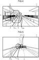
- FIG. 4 is a diagram for describing one example of the process for creating the detection-region database by the detection-region database creating device according to the present embodiment.
- the creating module 311 detects the fence of the platform included in a captured image F as a target position image S, and causes the display 203 to display the detection information representing that the target position image S has been detected. Then, in the case where the detected target position image S is the image of the opposing platform as illustrated in FIG. 4 , the creating module 311 creates the detection-region database (see Table 3 below) that associates the target position with the detection-region information of the extended region E on the left side of the defined region T (rolling stock gauge T1 or construction gauge T2) in the traveling direction Z of the railway vehicle RV.
- FIG. 5 is a diagram for describing one example of the process for creating the detection-region database by the detection-region database creating device according to the present embodiment.
- the creating module 311 detects the fence of the platform in the captured image F as the target position image S and causes the display 203 to display the detection information representing that the target position image S has been detected as illustrated in FIG. 5 . Then, in the case where the detected target position image S is the image of the island platform as illustrated in FIG. 5 , the creating module 311 creates the detection-region database (see Table 4 below) that associates the target position with the detection-region information of the extended region E on the right side of the defined region T (rolling stock gauge T1 or construction gauge T2) in the traveling direction Z of the railway vehicle RV.
- Table 4 Target position (km) Type number Effective range (m) Internal distance (m) Width (m) Lower distance (m) Height (m) 200.000 2 100 -1.5 2.0 1.5 2.0
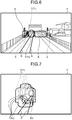
- FIG. 6 is a diagram for describing one example of the process for creating the detection-region database by the detection-region database creating device according to the present embodiment.
- the creating module 311 detects the crossing gate in the captured image F as the target position image S and causes the display 203 to display the detection information representing that the target position image S has been detected as illustrated in FIG. 6 .
- the creating module 311 creates the detection-region database (see Table 5 below) that associates the target position with the detection-region information of the extended region E on both sides of the defined region T (rolling stock gauge T1 or construction gauge T2).
- the creating module 311 increases the width of the extended region E on the side of the rail, which is installed in parallel to the rail where the railway vehicle RV travels, so as to be larger than the width of the extended region E on the side of the rail where the railway vehicle RV travels. For example, in the case where the vehicle keeps left, the creating module 311 increases the width of the extended region E on the right side in the traveling direction Z of the railway vehicle RV to be larger than the width of the extended region E on the left side in the traveling direction Z of the railway vehicle RV.
- FIG. 7 is a diagram for describing one example of the process for creating the detection-region database by the detection-region database creating device according to the present embodiment.
- the creating module 311 detects a railroad switch BG included in the captured image F.
- the creating module 311 creates the detection-region database (see Table 6 below) that associates the route information that can specify the route of the railway vehicle RV among the routes after the railroad switch BG (for example, the type number expressing the straight travel) with the switching position of the railroad switch BG.
- the detection region can be set only for the route where the railway vehicle RV advances and the obstacle that may interrupt the travel of the railway vehicle RV can be detected with higher accuracy.
- the switching position of the railroad switch BG is the distance (kilometrage) from a predetermined station to the railroad switch.
- FIG. 8 is a diagram for describing one example of the process for creating the detection-region database by the detection-region database creating device according to the present embodiment.
- the creating module 311 detects an entrance EG of a tunnel included in the captured image F as illustrated in FIG. 8 .
- the creating module 311 creates the detection-region database including the tunnel information (see Table 7 below) that associates the type number expressing the entrance EG of the tunnel with the tunnel entrance position corresponding to the position of the entrance EG of the tunnel.
- Table 7 Tunnel entrance position (km) Type number Effective range (m) Internal distance (m) Width (m) Lower distance (m) Height (m) 450.000 14 0.0 0.0 0.0 0.0 0.0 0.0 0.0 0.0 0.0
- the accuracy for detecting the obstacle using the captured image F can be increased by increasing the sensitivity of the sensor 101 in the railway vehicle RV when the railway vehicle RV travels in the tunnel, or the method of measuring the travel position of the railway vehicle RV can be changed from the measuring method using GNSS to the measuring method using an acceleration sensor, a gyro sensor, or the like.
- FIG. 9 is a diagram for describing one example of the process for creating the detection-region database by the detection-region database creating device according to the present embodiment.
- the creating module 311 detects an exit OG of the tunnel included in the captured image F as illustrated in FIG. 9 .
- the creating module 311 creates the detection-region database including the tunnel information (see Table 8 below) in which the type number representing the exit OG of the tunnel and the tunnel exit position corresponding to the position of the exit OG of the tunnel are associated with each other.
- Table 8 Tunnel exit position (km) Type number Effective range (m) Internal distance (m) Width (m) Lower distance (m) Height (m) 500.000 15 0.0 0.0 0.0 0.0 0.0 0.0 0.0 0.0 0.0
- the overexposure of the captured image F can be prevented by decreasing the sensitivity of the sensor 101 in the railway vehicle RV when the railway vehicle RV exits the tunnel, or the method of measuring the travel position of the railway vehicle RV can be returned to the measuring method using GNSS.
- FIG. 10 is a diagram illustrating one example of the database creation screen that is displayed on the detection-region database creating device according to the present embodiment.
- the creating module 311 causes the display 203 to display a database creation screen G including a moving image G1, an entry field G2, map information G3, and various buttons B1 to B7.
- a rewinding button B1 is a button that orders the rewinding of the moving image G1 (one example of captured image) displayed on the database creation screen G.
- a frame-rewinding button B2 is a button that orders rewinding of a frame of the moving image G1.
- a stop button B3 is a button that orders the stop of the playback of the moving image G1.
- a frame advance button B4 is a button that orders the frame advance of the moving image G1.
- a pause button B5 is a button that orders the pause of the playback of the moving image G1.
- a fast-forward button B6 is a button that orders fast-forwarding of the moving image G1.
- a creation order button B7 is a button that orders creation of the detection-region database.
- the creating module 311 causes the display 203 to display the database creation screen G including the moving image G1 in accordance with the operation of the buttons B1 to B6. In this case, for each frame of the moving image G1, the creating module 311 displays place and date information I1, which represents the travel position of the railway vehicle RV (for example, latitude and altitude, or kilometrage) and the date when the sensor 101 of the railway RV obtains the frame as illustrated in FIG. 10 .
- place and date information I1 represents the travel position of the railway vehicle RV (for example, latitude and altitude, or kilometrage) and the date when the sensor 101 of the railway RV obtains the frame as illustrated in FIG. 10 .
- the creating module 311 displays a reference line L drawn in the width direction X of the railway vehicle RV at the position at which the target position image is detected in each frame of the moving image G1 (for example, a predetermined distance that is set in advance (for example, 30 m) ahead of the end of the railway vehicle RV to the traveling direction of the railway vehicle RV).
- a predetermined distance that is set in advance for example, 30 m
- the map information G3 is a map including the travel position of the railway vehicle RV when the moving image G1 is obtained.
- the creating module 311 adds travel position display P, which represents the travel position of the railway vehicle RV, to the map information G3 as illustrated in FIG. 10 .
- the user of the detection-region database creating device D can work to create the detection-region database while seeing the entire travel section of the railway vehicle RV in the map information G3; therefore, the work of creating the detection-region database can be facilitated.
- the entry field G2 is the field that displays the indices of the detection-region database, the target position (for example, latitude and altitude, or kilometrage), the detection-region information (for example, type number, effective range, internal distance, width, lower distance, height, station/facility information corresponding to the information about the station or facility to which the target position belongs), and the transmission positional information by associating these pieces of information with each other.
- the target position for example, latitude and altitude, or kilometrage
- the detection-region information for example, type number, effective range, internal distance, width, lower distance, height, station/facility information corresponding to the information about the station or facility to which the target position belongs
- the transmission positional information by associating these pieces of information with each other.
- the creating module 311 displays the default values of the target position, the detection-region information, and the transmission positional information in the entry field G2 in the present embodiment.
- the default value of the target position is the travel position that is a predetermined distance (for example, 30 m) ahead of the travel position of the railway vehicle RV when the moving image G1 is obtained.
- the default value of the transmission positional information is the travel position that is a predetermined distance (for example, 200 m) before the travel position of the railway vehicle RV when the moving image G1 is obtained.
- the default value of the detection-region information is the detection-region information that is set in advance for each type of the target position.
- the user of the detection-region database creating device D can input the target position, the detection-region information, and the transmission positional information in the entry field G2 with reference to the default values of the target position, the detection-region information, and the transmission positional information displayed in the entry field G2.
- the creating module 311 creates the detection-region database that associates the target position, the detection-region information, and the transmission positional information input in the entry field G2 with each other.
- the creating module 311 creates the detection-region database including the detection-region information input to the entry field G2; however, it is only necessary that the detection-region database is created automatically on the basis of the captured image and the travel position. For example, the creating module 311 determines that the travel position that is a predetermined distance ahead of the travel position of the railway vehicle RV when the captured image is obtained is the target position. Furthermore, the creating module 311 converts the shape of the extended region (for example, the rectangular region) designated by the user of the detection-region database creating device D into the shape of the extended region with the actual size in the actual space in the captured image. Then, the creating module 311 may create, as the detection-region database, the database that associates the determined target position with the detection-region information expressing the shape of the extended region with the actual size.
- the creating module 311 may create, as the detection-region database, the database that associates the determined target position with the detection-region information expressing the shape of the extended region with the actual size.
- the detection-region database creating device D can be created on the basis of the information about the target position that cannot be seen from the image obtained by capturing the travel section of the railway vehicle RV from above; therefore, the detection-region database can be created that enables the obstacle for the railway vehicle RV to be detected with high accuracy.
Landscapes
- Engineering & Computer Science (AREA)
- Mechanical Engineering (AREA)
- Train Traffic Observation, Control, And Security (AREA)
- Information Retrieval, Db Structures And Fs Structures Therefor (AREA)
- Image Analysis (AREA)
Abstract
Description
- Embodiments of the present invention relate to a detection-region database creating device.
- To ensure the safety of a railway vehicle during the operation, it is necessary to check whether an object that interrupts the travel of the railway vehicle exists in the route of the railway vehicle. Hereinafter, the object is referred to as an obstacle. In view of this, equipment to prevent the occurrence of the obstacle or detecting equipment to detect the obstacle has been introduced in a section where the obstacle easily occurs in the route of the railway vehicle due to falling of a passenger or baggage from a platform, or getting stuck of an automobile or a bicycle in a railroad crossing.
- However, in a method in which the detecting equipment is introduced in the section where the obstacle easily occurs in the route of the railway vehicle, it is difficult to detect the obstacle in the entire route of the railway vehicle. In view of this, an obstacle detecting technique for detecting the obstacle by using a captured image resulting from the image capture of an area ahead of the railway vehicle by an image capturing device mounted in the railway vehicle has been developed.
- Japanese Patent Application Laid-open No.
2016-52849 - Incidentally, in the obstacle detecting technique, the obstacle is detected from a predetermined detection region in the captured image and it has been necessary to detect with high accuracy the obstacle existing in the route of the railway vehicle by extending the detection region in accordance with the travel position of the railway vehicle. In this case, it is desirable to create in advance a detection-region database that associates the travel position, among the travel positions of the railway vehicle, at which the detection region is extended with detection-region information representing the shape of the detection area at that travel position. As the method for creating the detection-region database, a method in which the database is created using, for example, an aerial photograph that is obtained by photographing the travel position of the railway vehicle from above, has been developed. In this method, however, it is difficult to know an end of the platform, the width and height of the platform, and the like exactly in the aerial photograph or the like. Therefore, it is difficult to create the detection-region database that enables the accurate detection of the obstacle existing in the route of the railway vehicle.
- A detection-region database creating device according to an embodiment includes an acquiring module, and a creating module. The acquiring module acquires, from a railway vehicle, a captured image obtained by capturing an image in a traveling direction of the railway vehicle by an image capturing device in the railway vehicle, and a travel position of the railway vehicle when the captured image is obtained. The creating module creates, on the basis of the captured image and the travel position, a detection-region database that associates a target position with detection-region information representing a three-dimensional shape of the extended region, the target position being a position corresponding to the travel position at which a detection region where an obstacle that interrupts travel of the railway vehicle in the captured image is detected is extended to an extended region outside a rolling stock gauge or a construction gauge of the railway vehicle.
-
-
FIG. 1 is a diagram illustrating one example of a structure of a safety travelling support system according to the present embodiment. -
FIG. 2 is a diagram illustrating one example of a function structure of an obstacle detection device and a controller of a detection-region database creating device for a railway vehicle according to the present embodiment. -
FIG. 3 is a diagram for describing one example of a process for creating a detection-region database by the detection-region database creating device according to the present embodiment. -
FIG. 4 is a diagram for describing one example of the process for creating the detection-region database by the detection-region database creating device according to the present embodiment. -
FIG. 5 is a diagram for describing one example of the process for creating the detection-region database by the detection-region database creating device according to the present embodiment. -
FIG. 6 is a diagram for describing one example of the process for creating the detection-region database by the detection-region database creating device according to the present embodiment. -
FIG. 7 is a diagram for describing one example of the process for creating the detection-region database by the detection-region database creating device according to the present embodiment. -
FIG. 8 is a diagram for describing one example of the process for creating the detection-region database by the detection-region database creating device according to the present embodiment. -
FIG. 9 is a diagram for describing one example of the process for creating the detection-region database by the detection-region database creating device according to the present embodiment. -
FIG. 10 is a diagram illustrating one example of a database creation screen that is displayed on the detection-region database creating device according to the present embodiment. - A safety travelling support system for railway system including a detection-region database creating device according to the present embodiment is described with reference to the drawings.
-
FIG. 1 is a diagram illustrating one example of a structure of the safety travelling support system according to the present embodiment. The safety travelling support system according to the present embodiment includes a railway vehicle RV and a detection-region database creating device D as illustrated inFIG. 1 . The railway vehicle RV and the detection-region database creating device D can communicate various pieces of information with each other through wireless communication or the like. - As illustrated in
FIG. 1 , the railway vehicle RV according to the present embodiment includes asensor 101, anobstacle detection device 102, arecording device 103, adisplay 104, and aposition measuring device 105. - The
sensor 101 is one example of an image capturing device that is provided so as to be able to capture an image in a traveling direction of the railway vehicle RV. Theobstacle detection device 102 is an obstacle detection device configured to detect an object that interrupts the travel of the railway vehicle RV. Hereinafter, the object described above is referred to as an obstacle. Therecording device 103 is a storage that stores therein the result of detecting the obstacle by theobstacle detection device 102. - The
display 104 displays various pieces of information including the captured image resulting from the image capture in the traveling direction of the railway vehicle RV by thesensor 101 and the result of detecting the obstacle by theobstacle detection device 102. The position measuringdevice 105 measures the travel position of the railway vehicle RV. In the present embodiment, theposition measuring device 105 measures the travel position of the railway vehicle RV using a rate generator (TG), a global navigation satellite system (GNSS), an acceleration sensor, a gyro sensor, or the like. - The detection-region database creating device D according to the present embodiment is a personal computer or the like. Specifically, the detection-region database creating device D includes a
controller 201, arecording device 202, and adisplay 203 as illustrated inFIG. 1 . - The
controller 201 controls the entire detection-region database creating device D. In the present embodiment, thecontroller 201 creates a database that associates a target position with the detection-region information. Hereinafter, the database described above is referred to as a detection-region database. Here, the target position corresponds to the travel position of the railway vehicle RV at which a region where the obstacle is detected in the captured image is extended to an extended region outside the rolling stock gauge or the construction gauge of the railway vehicle RV. Hereinafter, the region described is referred to as a detection region. The detection-region information corresponds to the information representing the three-dimensional shape of the extended region at the target position. - The
recording device 202 stores therein various pieces of information including the captured image obtained by the image capture of thesensor 101 mounted on the railway vehicle RV. Thedisplay 203 is a liquid crystal display (LCD) or the like, and displays a screen used to create the detection-region database. Hereinafter, the screen described above is referred to as a database creation screen. -
FIG. 2 is a diagram illustrating one example of a function structure of the obstacle detection device and the controller of the detection-region database creating device for the railway vehicle according to the present embodiment. Theobstacle detection device 102 in the railway vehicle RV includes animage acquiring module 301, arail recognizing module 302, a detection-region recognizing module 303, an obstaclecandidate recognizing module 304, anobstacle determination module 305, and aresult outputting module 306 as illustrated inFIG. 2 . - In the present embodiment, the
image acquiring module 301, therail recognizing module 302, the detection-region recognizing module 303, the obstaclecandidate recognizing module 304, theobstacle determination module 305, and theresult outputting module 306 are partially or entirely implemented by having a processor such as a central processing unit (CPU) in the railway vehicle RV execute software stored in therecording device 103, for example. - The
image acquiring module 301, therail recognizing module 302, the detection-region recognizing module 303, the obstaclecandidate recognizing module 304, theobstacle determination module 305, and theresult outputting module 306 may be partially or entirely implemented by hardware corresponding to a circuit board such as Large Scale Integration (LSI), Application Specific Integrated Circuit (ASIC), or Field Programmable Integrated Circuit (FPGA). Alternatively, theimage acquiring module 301, therail recognizing module 302, the detection-region recognizing module 303, the obstaclecandidate recognizing module 304, theobstacle determination module 305, and theresult outputting module 306 may be implemented by cooperation of hardware and software executed by the processor. - A
storage 307 includes a nonvolatile storage medium such as a read only memory (ROM), a flash memory, a hard disk drive (HDD), or an SD card, and a volatile storage medium such as a random access memory (RAM) or a register. Thestorage 307 stores therein various pieces of information including the detection-region database. - The
image acquiring module 301 acquires the captured image resulting from the image capture in the traveling direction of the railway vehicle RV by thesensor 101. Therail recognizing module 302 detects the rail where the railway vehicle RV travels from the captured image. - The detection-
region recognizing module 303 sets a three-dimensional detection region for the captured image on the basis of the rail detected by therail recognizing module 302. Here, the detection region corresponds to a three-dimensional region including a defined region that is defined by the rolling stock gauge or the construction gauge of the railway vehicle RV in the captured image. - When the railway vehicle RV travels at the target position, the detection-
region recognizing module 303 extends the detection region to the extended region. Specifically, the detection-region recognizing module 303 receives in advance the detection-region database from the detection-region database creating device D. The detection-region database is a database that associates the target position (for example, kilometrage, or latitude and altitude) with the detection-region information representing the three-dimensional shape of the extended region. - In the present embodiment, the detection-region database associates the position of a railroad switch existing in the route of the railway vehicle RV with the route information representing the route of the railway vehicle RV after the railroad switch. Hereinafter, the position described above is referred to as a switching position, for example kilometrage, or latitude and altitude. Furthermore, in the present embodiment, the detection-region database includes the position of a tunnel existing in the route of the railway vehicle RV. Hereinafter, the position described above is referred to as a tunnel position, for example kilometrage, or latitude and altitude.
- Next, the detection-
region recognizing module 303 specifies the detection-region information associated with the target position that coincides with the travel position of the railway vehicle RV measured by theposition measuring device 105 in the detection-region database. Then, on the basis of the specified detection-region information, the detection-region recognizing module 303 extends the detection region so that the detection region can include the extended region at the target position. - Thus, for example, setting, as the target position, a railroad crossing where a pedestrian, a bicycle, an automobile, or the like crossing the rail may become an obstacle that interrupts the travel of the railway vehicle RV, or a platform from which a passenger or baggage can fall on the rail and may become an obstacle that interrupts the travel of the railway vehicle RV, also makes it possible to detect the object that is highly likely to become the obstacle in the travel of the railway vehicle RV around the rolling stock gauge or the construction gauge as the obstacle. As a result, it becomes possible to grasp the circumstances around the railway vehicle RV, and thus to reduce the risk that the object enters the rolling stock gauge or the construction gauge after the railway vehicle RV gets close to the railroad crossing or the platform and is brought into contact with the railway vehicle RV.
- In addition, when the travel position measured by the
position measuring device 105 coincides with the switching position associated with the route information in the detection-region database, the detection-region recognizing module 303 sets the detection region for only the route represented by the route information among a plurality of routes after the railroad switch. Thus, it is possible to prevent the object that exists in the route where the railway vehicle RV does not advance from being detected as the obstacle. - Furthermore, when the travel position measured by the
position measuring device 105 coincides with the tunnel position included in the detection-region database (for example, the entrance and the exit of the tunnel), the detection-region recognizing module 303 changes the method of measuring the travel position by theposition measuring device 105 or the image capture condition of thesensor 101. - Specifically, when the travel position measured by the
position measuring device 105 coincides with the entrance of the tunnel included in the detection-region database, the detection-region recognizing module 303 changes the method of measuring the travel position by theposition measuring device 105 from the measuring method using GNSS to a measuring method using TG, an acceleration sensor, or a gyro sensor. In addition, when the travel position measured by theposition measuring device 105 coincides with the entrance of the tunnel included in the detection-region database, the detection-region recognizing module 303 increases the sensitivity of thesensor 101. - On the other hand, when the travel position measured by the
position measuring device 105 coincides with the exit of the tunnel included in the detection-region database, the detection-region recognizing module 303 returns the method of measuring the travel position by theposition measuring device 105 to the measuring method using GNSS. In addition, when the travel position measured by theposition measuring device 105 coincides with the exit of the tunnel in the detection-region database, the detection-region recognizing module 303 decreases the sensitivity of thesensor 101. - The obstacle
candidate recognizing module 304 extracts objects included in the detection region as candidates for the obstacle (obstacle candidates) on the basis of the captured image having the detection region defined therein. Theobstacle determination module 305 detects the obstacle from among the obstacle candidates extracted by the obstaclecandidate recognizing module 304 on the basis of at least one of the size of the obstacle candidates and motion vectors of the obstacle candidates. Thus, the object that is more likely to become the obstacle among the objects existing in the detection region can be detected as the obstacle; therefore, the obstacle can be detected with higher accuracy. - The
result outputting module 306 outputs the result of detecting the obstacle by theobstacle determination module 305. Moreover, theresult outputting module 306 adds the travel position of the railway vehicle RV, the travel position being measured by theposition measuring device 105 when the captured image is obtained by thesensor 101, to the obtained captured image and transmits the obtained data to the detection-region database creating device D. - Next, the function structure of the detection-region database creating device D is described. As illustrated in
FIG. 2 , the detection-region database creating device D includes an acquiringmodule 310, a creatingmodule 311, anoutputting module 312, and astorage 313. - In the present embodiment, the acquiring
module 310, the creatingmodule 311, and theoutputting module 312 are partially or entirely implemented by having the processor such as a CPU in the detection-region database creating device D execute software stored in therecording device 202. - The acquiring
module 310, the creatingmodule 311, and theoutputting module 312 may be partially or entirely implemented by hardware, which is a circuit board such as LSI, ASIC, or FPGA. Alternatively, the acquiringmodule 310, the creatingmodule 311, and theoutputting module 312 may be implemented by cooperation of hardware and software executed by the processor. - The
storage 313 includes a nonvolatile storage medium such as a ROM, a flash memory, an HDD, or an SD card, and a volatile storage medium such as a RAM or a register. Thestorage 313 stores therein various pieces of information including the detection-region database. - The acquiring
module 310 acquires from the railway vehicle RV, the captured image and the travel position of the railway vehicle RV when the captured image is obtained. Then, the acquiringmodule 310 associates the acquired captured image with the travel position of the railway vehicle RV when the captured image is obtained, and stores the associated data in therecording device 202. For example, the information may be acquired from the railway vehicle RV offline at the railyard or the station after a predetermined travel, or from the railway vehicle RV in real time through a radio line during the travel. - The creating
module 311 creates the detection-region database on the basis of the captured image and the travel position of the railway vehicle RV that are stored in association with each other in therecording device 202. Then, the creatingmodule 311 stores the created detection-region database in thestorage 313. - Thus, the detection-region database can be created on the basis of the information about the target position (for example, the height or width of the platform) that cannot be seen from the image obtained by capturing the travel section of the railway vehicle RV from above (for example, aerial photograph); therefore, the detection-region database can be created that enables the obstacle for the railway vehicle RV to be detected with high accuracy.
- Here, one example of the detection-region database is described.
FIG. 3 is a diagram for describing one example of a process for creating the detection-region database by the detection-region database creating device according to the present embodiment. In the present embodiment, the detection-region database associates the target position (for example, kilometrage) with the detection-region information as illustrated in Table 1 below. - As illustrated in Table 1, the detection-region information includes a type number, an effective range N1, an internal distance N2, a width N3, a lower distance N4, and a height N5. In addition, the detection-region information may include positional information of the extended region at the target position. For example, the detection-region information may include the positional information representing whether the extended region exists on the right side or the left side in a width direction X (see
FIG. 3 ) of the railway vehicle RV on the basis of a rail R where the railway vehicle RV travels. In the present embodiment, the detection-region database may include transmission positional information by associating this transmission positional information with the target position. The transmission positional information can specify the transmission position from which the detection-region database is transmitted to the railway vehicle RV.Table 1 Target position (km) Type number Effective range (m) Internal distance (m) Width (m) Lower distance (m) Height (m) 100.000 1 100 1.5 2.0 1.5 2.0 - The type number is the number that represents the type of the target position, for example a left platform in the traveling direction of the railway vehicle RV (opposing platform), a right platform in the traveling direction of the railway vehicle RV (island platform), a left crossing gate in the traveling direction of the railway vehicle RV, a right crossing gate in the traveling direction of the railway vehicle RV, a sign, a traffic light, a tunnel, or a railway bridge. In the present embodiment, the detection-region database creating device D stores in the
storage 313 or the like, a type database (see Table 2 below) that associates the type number with the type of the target position. Then, when the user of the detection-region database creating device D creates the detection-region database, the creatingmodule 311 causes thedisplay 203 to display the type database so that the type database can be used as a reference.Table 2 Type number Type of target position 1 Opposing platform 2 Island platform 3 Crossing gate (left) 4 Crossing gate (right) ... ... - The effective range N1 is the depth of an extended region E that exists outside a defined region T (rolling stock gauge T1 or construction gauge T2) or the length of the extended region E to a traveling direction Z of the railway vehicle RV as illustrated in
FIG. 3 . The internal distance N2 is the distance from an intermediate point between the rails R in the width direction X of the railway vehicle RV to the inner end of the extended region E as illustrated inFIG. 3 . The width N3 is the width of the extended region E in the width direction X of the railway vehicle RV as illustrated inFIG. 3 . The lower distance N4 is the distance from the rail R to the lower end of the extended region E in a height direction Y of the railway vehicle RV as illustrated inFIG. 3 . The height N5 is the height of the extended region E in the height direction Y of the railway vehicle RV as illustrated inFIG. 3 . - Back to
FIG. 2 , in the present embodiment, the creatingmodule 311 causes thedisplay 203 to display a screen including the captured image and an entry field. Hereinafter, the screen described above is referred to as a database creation screen. Here, the entry field is the field that displays the target position and the detection-region information that are input by the user of the detection-region database creating device D. Thus, the user of the detection-region database creating device D can input the target position and the detection-region information while seeing the captured image displayed on thedisplay 203; therefore, the work of creating the detection-region database can be facilitated. In this case, the creatingmodule 311 creates the detection-region database that associates the target position with the detection-region information that are input using the entry field. - In the present embodiment, the creating
module 311 detects an image that symbolizes the target position from the captured image by an image recognition process. Hereinafter, the image described above is referred to as a target position image. Specifically, the creatingmodule 311 detects the fence of the platform, the crossing gate, the dedicated sign, the traffic light, or the like as the target position image from the captured image. In the present embodiment, the creatingmodule 311 detects, as the target position image, the image that symbolizes the target position existing a predetermined distance (for example, 30 m) ahead of the end of the railway vehicle RV to the traveling direction Z of the railway vehicle RV. - Then, upon the detection of the target position image, the creating
module 311 causes thedisplay 203 to display the detection information expressing that the target position image has been detected (for example, a message expressing that the target position image has been detected). Thus, when the user of the detection-region database creating device D creates the detection-region database while seeing the captured image displayed on thedisplay 203, the user can easily recognize that the target position image is included in the captured image; therefore, the work of creating the detection-region database can be facilitated. - In the present embodiment, the creating
module 311 causes thedisplay 203 to display a preview image in which a detection-region image corresponding to the image representing the detection region is overlapped on the captured image, on the basis of the created detection-region database. Thus, the detection region can be seen on the captured image and therefore, the detection-region database can be created that enables the obstacle for the railway vehicle RV to be detected with higher accuracy. - In addition, in the present embodiment, the creating
module 311 causes thedisplay 203 to display the database creation screen including map information. Here, the map information is a map in which the travel position of the railway vehicle RV when the captured image is obtained can be specified. Thus, the user of the detection-region database creating device D can work to create the detection-region database while seeing the entire travel section of the railway vehicle RV by the map information displayed on thedisplay 203; therefore, the work of creating the detection-region database can be facilitated. - The
outputting module 312 transmits (outputs) the detection-region database stored in thestorage 313 to the railway vehicle RV. In the present embodiment, in the case where the detection-region database includes the transmission positional information, when the railway vehicle RV has reached the transmission position represented by the transmission positional information (for example, 200 m before the target position), theoutputting module 312 transmits to the railway vehicle RV, the detection-region database including the detection-region information and the target position associated with the transmission positional information. -
FIG. 4 is a diagram for describing one example of the process for creating the detection-region database by the detection-region database creating device according to the present embodiment. For example, as illustrated inFIG. 4 , the creatingmodule 311 detects the fence of the platform included in a captured image F as a target position image S, and causes thedisplay 203 to display the detection information representing that the target position image S has been detected. Then, in the case where the detected target position image S is the image of the opposing platform as illustrated inFIG. 4 , the creatingmodule 311 creates the detection-region database (see Table 3 below) that associates the target position with the detection-region information of the extended region E on the left side of the defined region T (rolling stock gauge T1 or construction gauge T2) in the traveling direction Z of the railway vehicle RV.Table 3 Target position (km) Type number Effective range (m) Internal distance (m) Width (m) Lower distance (m) Height (m) 100.000 1 100 1.5 2.0 1.5 2.0 -
FIG. 5 is a diagram for describing one example of the process for creating the detection-region database by the detection-region database creating device according to the present embodiment. For example, the creatingmodule 311 detects the fence of the platform in the captured image F as the target position image S and causes thedisplay 203 to display the detection information representing that the target position image S has been detected as illustrated inFIG. 5 . Then, in the case where the detected target position image S is the image of the island platform as illustrated inFIG. 5 , the creatingmodule 311 creates the detection-region database (see Table 4 below) that associates the target position with the detection-region information of the extended region E on the right side of the defined region T (rolling stock gauge T1 or construction gauge T2) in the traveling direction Z of the railway vehicle RV.Table 4 Target position (km) Type number Effective range (m) Internal distance (m) Width (m) Lower distance (m) Height (m) 200.000 2 100 -1.5 2.0 1.5 2.0 -
FIG. 6 is a diagram for describing one example of the process for creating the detection-region database by the detection-region database creating device according to the present embodiment. For example, the creatingmodule 311 detects the crossing gate in the captured image F as the target position image S and causes thedisplay 203 to display the detection information representing that the target position image S has been detected as illustrated inFIG. 6 . Then, as illustrated inFIG. 6 , in the case where the detected target position image S is the crossing gate, the creatingmodule 311 creates the detection-region database (see Table 5 below) that associates the target position with the detection-region information of the extended region E on both sides of the defined region T (rolling stock gauge T1 or construction gauge T2).Table 5 Target position (km) Type number Effective range (m) Internal distance (m) Width (m) Lower distance (m) Height (m) 300.000 3 10 2.0 3.0 0.0 8.0 300.000 4 10 2.0 6.0 0.0 8.0 - As illustrated in
FIG. 6 , in the case where the target position image S is the crossing gate and the target position is a double track, the creatingmodule 311 increases the width of the extended region E on the side of the rail, which is installed in parallel to the rail where the railway vehicle RV travels, so as to be larger than the width of the extended region E on the side of the rail where the railway vehicle RV travels. For example, in the case where the vehicle keeps left, the creatingmodule 311 increases the width of the extended region E on the right side in the traveling direction Z of the railway vehicle RV to be larger than the width of the extended region E on the left side in the traveling direction Z of the railway vehicle RV. -
FIG. 7 is a diagram for describing one example of the process for creating the detection-region database by the detection-region database creating device according to the present embodiment. For example, as illustrated inFIG. 7 , the creatingmodule 311 detects a railroad switch BG included in the captured image F. Upon the detection of the railroad switch BG from the captured image F, the creatingmodule 311 creates the detection-region database (see Table 6 below) that associates the route information that can specify the route of the railway vehicle RV among the routes after the railroad switch BG (for example, the type number expressing the straight travel) with the switching position of the railroad switch BG.Table 6 Switching position (km) Type number Effective range (m) Internal distance (m) Width (m) Lower distance (m) Height (m) 400.000 13 0.0 0.0 0.0 0.0 0.0 - Thus, when the detection-
region recognizing module 303 in the railway vehicle RV sets the detection region in the captured image F, the detection region can be set only for the route where the railway vehicle RV advances and the obstacle that may interrupt the travel of the railway vehicle RV can be detected with higher accuracy. In the present embodiment, the switching position of the railroad switch BG is the distance (kilometrage) from a predetermined station to the railroad switch. -
FIG. 8 is a diagram for describing one example of the process for creating the detection-region database by the detection-region database creating device according to the present embodiment. For example, the creatingmodule 311 detects an entrance EG of a tunnel included in the captured image F as illustrated inFIG. 8 . Upon the detection of the entrance EG of the tunnel from the captured image F, the creatingmodule 311 creates the detection-region database including the tunnel information (see Table 7 below) that associates the type number expressing the entrance EG of the tunnel with the tunnel entrance position corresponding to the position of the entrance EG of the tunnel.Table 7 Tunnel entrance position (km) Type number Effective range (m) Internal distance (m) Width (m) Lower distance (m) Height (m) 450.000 14 0.0 0.0 0.0 0.0 0.0 - Thus, the accuracy for detecting the obstacle using the captured image F can be increased by increasing the sensitivity of the
sensor 101 in the railway vehicle RV when the railway vehicle RV travels in the tunnel, or the method of measuring the travel position of the railway vehicle RV can be changed from the measuring method using GNSS to the measuring method using an acceleration sensor, a gyro sensor, or the like. -
FIG. 9 is a diagram for describing one example of the process for creating the detection-region database by the detection-region database creating device according to the present embodiment. For example, the creatingmodule 311 detects an exit OG of the tunnel included in the captured image F as illustrated inFIG. 9 . Upon the detection of the exit OG of the tunnel from the captured image F, the creatingmodule 311 creates the detection-region database including the tunnel information (see Table 8 below) in which the type number representing the exit OG of the tunnel and the tunnel exit position corresponding to the position of the exit OG of the tunnel are associated with each other.Table 8 Tunnel exit position (km) Type number Effective range (m) Internal distance (m) Width (m) Lower distance (m) Height (m) 500.000 15 0.0 0.0 0.0 0.0 0.0 - Thus, the overexposure of the captured image F can be prevented by decreasing the sensitivity of the
sensor 101 in the railway vehicle RV when the railway vehicle RV exits the tunnel, or the method of measuring the travel position of the railway vehicle RV can be returned to the measuring method using GNSS. -
FIG. 10 is a diagram illustrating one example of the database creation screen that is displayed on the detection-region database creating device according to the present embodiment. For example, as illustrated inFIG. 10 , the creatingmodule 311 causes thedisplay 203 to display a database creation screen G including a moving image G1, an entry field G2, map information G3, and various buttons B1 to B7. - A rewinding button B1 is a button that orders the rewinding of the moving image G1 (one example of captured image) displayed on the database creation screen G. A frame-rewinding button B2 is a button that orders rewinding of a frame of the moving image G1. A stop button B3 is a button that orders the stop of the playback of the moving image G1. A frame advance button B4 is a button that orders the frame advance of the moving image G1. A pause button B5 is a button that orders the pause of the playback of the moving image G1. A fast-forward button B6 is a button that orders fast-forwarding of the moving image G1. A creation order button B7 is a button that orders creation of the detection-region database.
- The creating
module 311 causes thedisplay 203 to display the database creation screen G including the moving image G1 in accordance with the operation of the buttons B1 to B6. In this case, for each frame of the moving image G1, the creatingmodule 311 displays place and date information I1, which represents the travel position of the railway vehicle RV (for example, latitude and altitude, or kilometrage) and the date when thesensor 101 of the railway RV obtains the frame as illustrated inFIG. 10 . - As illustrated in
FIG. 10 , the creatingmodule 311 displays a reference line L drawn in the width direction X of the railway vehicle RV at the position at which the target position image is detected in each frame of the moving image G1 (for example, a predetermined distance that is set in advance (for example, 30 m) ahead of the end of the railway vehicle RV to the traveling direction of the railway vehicle RV). Thus, the user of the detection-region database creating device D can easily find the position of the target position image in the moving image G1. - The map information G3 is a map including the travel position of the railway vehicle RV when the moving image G1 is obtained. The creating
module 311 adds travel position display P, which represents the travel position of the railway vehicle RV, to the map information G3 as illustrated inFIG. 10 . Thus, the user of the detection-region database creating device D can work to create the detection-region database while seeing the entire travel section of the railway vehicle RV in the map information G3; therefore, the work of creating the detection-region database can be facilitated. - The entry field G2 is the field that displays the indices of the detection-region database, the target position (for example, latitude and altitude, or kilometrage), the detection-region information (for example, type number, effective range, internal distance, width, lower distance, height, station/facility information corresponding to the information about the station or facility to which the target position belongs), and the transmission positional information by associating these pieces of information with each other.
- In the case where the target position, the detection-region information, or the transmission positional information is not input in the entry field G2, the creating
module 311 displays the default values of the target position, the detection-region information, and the transmission positional information in the entry field G2 in the present embodiment. Here, the default value of the target position is the travel position that is a predetermined distance (for example, 30 m) ahead of the travel position of the railway vehicle RV when the moving image G1 is obtained. The default value of the transmission positional information is the travel position that is a predetermined distance (for example, 200 m) before the travel position of the railway vehicle RV when the moving image G1 is obtained. The default value of the detection-region information is the detection-region information that is set in advance for each type of the target position. - The user of the detection-region database creating device D can input the target position, the detection-region information, and the transmission positional information in the entry field G2 with reference to the default values of the target position, the detection-region information, and the transmission positional information displayed in the entry field G2. After that, when the creation order button B7 is pushed to order the creation of the detection-region database, the creating
module 311 creates the detection-region database that associates the target position, the detection-region information, and the transmission positional information input in the entry field G2 with each other. - In the present embodiment, the creating
module 311 creates the detection-region database including the detection-region information input to the entry field G2; however, it is only necessary that the detection-region database is created automatically on the basis of the captured image and the travel position. For example, the creatingmodule 311 determines that the travel position that is a predetermined distance ahead of the travel position of the railway vehicle RV when the captured image is obtained is the target position. Furthermore, the creatingmodule 311 converts the shape of the extended region (for example, the rectangular region) designated by the user of the detection-region database creating device D into the shape of the extended region with the actual size in the actual space in the captured image. Then, the creatingmodule 311 may create, as the detection-region database, the database that associates the determined target position with the detection-region information expressing the shape of the extended region with the actual size. - Thus, by the detection-region database creating device D according to the present embodiment, the detection-region database can be created on the basis of the information about the target position that cannot be seen from the image obtained by capturing the travel section of the railway vehicle RV from above; therefore, the detection-region database can be created that enables the obstacle for the railway vehicle RV to be detected with high accuracy.
- The embodiment of the present invention has been described so far; however, this embodiment is just an illustrative example and does not intend to limit the scope of the invention. This novel embodiment can be carried out in other various modes, and various omissions, replacements, and changes are possible within the range not departing from the concept of the invention. The embodiment and the modifications thereof are included in the scope and the concept of the invention, and are included in the invention according to the scope of claims and the equivalent thereof.
Claims (6)
- A detection-region database creating device comprising:an acquiring module that acquires, from a railway vehicle, a captured image obtained by capturing an image in a traveling direction of the railway vehicle by an image capturing device in the railway vehicle, and a travel position of the railway vehicle when the captured image is obtained; anda creating module that creates, on the basis of the captured image and the travel position, a detection-region database that associates a target position with detection-region information expressing a three-dimensional shape of the extended region, the target position being a position corresponding to the travel position at which a detection region where an obstacle that interrupts travel of the railway vehicle in the captured image is detected is extended to an extended region outside a rolling stock gauge or a construction gauge of the railway vehicle.
- The detection-region database creating device according to claim 1, wherein the creating module causes a display to display a screen including the captured image and an entry field where the target position and the detection-region information are input, and creates the detection-region database that associates the detection-region information with the target position that are input using the entry field.
- The detection-region database creating device according to claim 2, wherein the creating module further detects a target position image expressing the target position from the captured image by an image recognition process, and causes the display to display detection information expressing that the target position image has been detected.
- The detection-region database creating device according to claim 2 or 3, wherein the creating module further causes the display to display a preview image in which a detection-region image expressing the detection region is overlapped with the captured image on the basis of the created detection-region database.
- The detection-region database creating device according to any one of claims 1 to 4, wherein the creating module further detects a railroad switch existing in a route of the railway vehicle from the captured image by the image recognition process, and creates the detection-region database including route information expressing a route of the railway vehicle after the detected railroad switch.
- The detection-region database creating device according to any one of claims 2 to 4, wherein the creating module causes the display to display the screen including map information that is able to specify the travel position when the captured image is obtained.
Applications Claiming Priority (2)
| Application Number | Priority Date | Filing Date | Title |
|---|---|---|---|
| JP2018120441A JP7068068B2 (en) | 2018-06-26 | 2018-06-26 | Detection area database creation device |
| PCT/JP2019/025250 WO2020004424A1 (en) | 2018-06-26 | 2019-06-25 | Detection-region database creating device |
Publications (2)
| Publication Number | Publication Date |
|---|---|
| EP3816013A1 true EP3816013A1 (en) | 2021-05-05 |
| EP3816013A4 EP3816013A4 (en) | 2022-03-23 |
Family
ID=68986689
Family Applications (1)
| Application Number | Title | Priority Date | Filing Date |
|---|---|---|---|
| EP19824624.1A Pending EP3816013A4 (en) | 2018-06-26 | 2019-06-25 | DETECTION REGION DATABASE CREATION DEVICE |
Country Status (5)
| Country | Link |
|---|---|
| EP (1) | EP3816013A4 (en) |
| JP (1) | JP7068068B2 (en) |
| CN (1) | CN112399942B (en) |
| SG (1) | SG11202012907UA (en) |
| WO (1) | WO2020004424A1 (en) |
Cited By (1)
| Publication number | Priority date | Publication date | Assignee | Title |
|---|---|---|---|---|
| CN116124157A (en) * | 2021-11-12 | 2023-05-16 | 株式会社东芝 | Information processing device and program |
Families Citing this family (5)
| Publication number | Priority date | Publication date | Assignee | Title |
|---|---|---|---|---|
| JP2024099137A (en) * | 2023-01-12 | 2024-07-25 | 東芝インフラシステムズ株式会社 | Railway vehicle control system and railway vehicle control method |
| CN116128834B (en) * | 2023-02-01 | 2025-07-01 | 河南理工大学 | Rapid detection method of rail transit platform clearance based on 3D laser scanning |
| WO2025069359A1 (en) * | 2023-09-29 | 2025-04-03 | 日本電気株式会社 | Determination system, determination method, and recording medium |
| CN117575443B (en) * | 2024-01-17 | 2024-04-19 | 金华市浙中公铁联运港有限公司 | Intelligent management method and system for railway station parking area |
| CN120440090B (en) * | 2025-07-14 | 2025-11-25 | 湖南中车时代通信信号有限公司 | Train track-in control method, device, equipment and medium |
Family Cites Families (10)
| Publication number | Priority date | Publication date | Assignee | Title |
|---|---|---|---|---|
| JPH07119560B2 (en) * | 1991-05-27 | 1995-12-20 | 東海旅客鉄道株式会社 | Tunnel section management device |
| JP3244870B2 (en) * | 1993-04-28 | 2002-01-07 | 東日本旅客鉄道株式会社 | Obstacle detection device for railway vehicles |
| JP2002008019A (en) * | 2000-06-21 | 2002-01-11 | Fuji Heavy Ind Ltd | Track recognition device and railway vehicle using the track recognition device |
| DE102014206473A1 (en) * | 2014-04-03 | 2015-10-08 | Bombardier Transportation Gmbh | Automatic assistance to a driver of a lane-bound vehicle, in particular a rail vehicle |
| JP6209141B2 (en) | 2014-09-04 | 2017-10-04 | 公益財団法人鉄道総合技術研究所 | Obstacle detection apparatus and method |
| DE102014220778A1 (en) * | 2014-10-14 | 2016-04-14 | Robert Bosch Gmbh | Method for monitoring track sections in a rail vehicle |
| CN104777521A (en) * | 2015-03-24 | 2015-07-15 | 广州市地下铁道总公司 | Binocular-vision-based detection system for foreign matter between train door and platform shield gate, as well as detection method for detection system |
| JP6346868B2 (en) * | 2015-03-31 | 2018-06-20 | 公益財団法人鉄道総合技術研究所 | Stereo image processing method and apparatus |
| JP6428713B2 (en) * | 2015-07-29 | 2018-11-28 | 株式会社デンソー | Information display device |
| JP7062407B2 (en) * | 2017-11-02 | 2022-05-06 | 株式会社東芝 | Obstacle detection device |
-
2018
- 2018-06-26 JP JP2018120441A patent/JP7068068B2/en active Active
-
2019
- 2019-06-25 SG SG11202012907UA patent/SG11202012907UA/en unknown
- 2019-06-25 CN CN201980042667.9A patent/CN112399942B/en active Active
- 2019-06-25 EP EP19824624.1A patent/EP3816013A4/en active Pending
- 2019-06-25 WO PCT/JP2019/025250 patent/WO2020004424A1/en not_active Ceased
Cited By (2)
| Publication number | Priority date | Publication date | Assignee | Title |
|---|---|---|---|---|
| CN116124157A (en) * | 2021-11-12 | 2023-05-16 | 株式会社东芝 | Information processing device and program |
| EP4181090A1 (en) * | 2021-11-12 | 2023-05-17 | Kabushiki Kaisha Toshiba | Information processing apparatus and program |
Also Published As
| Publication number | Publication date |
|---|---|
| JP2020001476A (en) | 2020-01-09 |
| CN112399942A (en) | 2021-02-23 |
| JP7068068B2 (en) | 2022-05-16 |
| SG11202012907UA (en) | 2021-02-25 |
| EP3816013A4 (en) | 2022-03-23 |
| CN112399942B (en) | 2023-09-08 |
| WO2020004424A1 (en) | 2020-01-02 |
Similar Documents
| Publication | Publication Date | Title |
|---|---|---|
| JP7062407B2 (en) | Obstacle detection device | |
| CN112399942B (en) | Detection area database creation device | |
| US9810533B2 (en) | Railway track monitoring | |
| CN104183131B (en) | Use the device and method in wireless communication detection track | |
| KR101055331B1 (en) | Railway vehicle operation management system and railway vehicle operation management program | |
| EP3415400A1 (en) | System and method for determining the position of a guided vehicle | |
| US12384434B2 (en) | Sensor performance evaluation system and method, and automatic driving system | |
| KR102053918B1 (en) | Unmanned vehicle, system and method for inspecting railway facilities using unmanned vehicle | |
| JP6855712B2 (en) | Turnout entry possibility judgment device and turnout entry possibility judgment method | |
| CN103105168A (en) | Method for position determination | |
| US20170103271A1 (en) | Driving assistance system and driving assistance method for vehicle | |
| CN115512568B (en) | Control device, moving body, control method, and computer-readable storage medium | |
| KR102144778B1 (en) | System and method for providing real-time updated road information | |
| CN112298597A (en) | Self-propelled vehicle | |
| Faizan et al. | Design and development of in-vehicle lane departure warning system using standard global positioning system receiver | |
| CN115457805B (en) | Control device, mobile body, control method and computer-readable storage medium | |
| JP7382849B2 (en) | Driving assistance systems, driving assistance methods, and driving assistance programs | |
| JP7593452B2 (en) | Driving assistance system, driving assistance method, and program | |
| KR102630223B1 (en) | System for inspecting road facilities and its inspection method based on GNSS | |
| JP2018146462A (en) | Information output device and information output method | |
| US20230331269A1 (en) | Train jolt determination system | |
| JP7210157B2 (en) | Fixed position stop control device | |
| WO2019194293A1 (en) | Railway track inspection device | |
| JP6552944B2 (en) | Information processing apparatus and vehicle | |
| JP2020005464A (en) | Travel control device |
Legal Events
| Date | Code | Title | Description |
|---|---|---|---|
| STAA | Information on the status of an ep patent application or granted ep patent |
Free format text: STATUS: THE INTERNATIONAL PUBLICATION HAS BEEN MADE |
|
| PUAI | Public reference made under article 153(3) epc to a published international application that has entered the european phase |
Free format text: ORIGINAL CODE: 0009012 |
|
| STAA | Information on the status of an ep patent application or granted ep patent |
Free format text: STATUS: REQUEST FOR EXAMINATION WAS MADE |
|
| 17P | Request for examination filed |
Effective date: 20201216 |
|
| AK | Designated contracting states |
Kind code of ref document: A1 Designated state(s): AL AT BE BG CH CY CZ DE DK EE ES FI FR GB GR HR HU IE IS IT LI LT LU LV MC MK MT NL NO PL PT RO RS SE SI SK SM TR |
|
| DAV | Request for validation of the european patent (deleted) | ||
| DAX | Request for extension of the european patent (deleted) | ||
| A4 | Supplementary search report drawn up and despatched |
Effective date: 20220218 |
|
| RIC1 | Information provided on ipc code assigned before grant |
Ipc: B61L 23/04 20060101ALI20220215BHEP Ipc: B61L 25/02 20060101ALI20220215BHEP Ipc: B61L 15/00 20060101ALI20220215BHEP Ipc: G06T 7/00 20170101ALI20220215BHEP Ipc: G06F 16/00 20190101ALI20220215BHEP Ipc: B61L 25/04 20060101ALI20220215BHEP Ipc: B61L 23/00 20060101AFI20220215BHEP |
|
| STAA | Information on the status of an ep patent application or granted ep patent |
Free format text: STATUS: EXAMINATION IS IN PROGRESS |
|
| 17Q | First examination report despatched |
Effective date: 20250709 |
|
| RAP1 | Party data changed (applicant data changed or rights of an application transferred) |
Owner name: KABUSHIKI KAISHA TOSHIBA |