EP3815955A1 - Travel control device - Google Patents
Travel control device Download PDFInfo
- Publication number
- EP3815955A1 EP3815955A1 EP19827088.6A EP19827088A EP3815955A1 EP 3815955 A1 EP3815955 A1 EP 3815955A1 EP 19827088 A EP19827088 A EP 19827088A EP 3815955 A1 EP3815955 A1 EP 3815955A1
- Authority
- EP
- European Patent Office
- Prior art keywords
- train
- unit
- travel control
- relative distance
- travel
- Prior art date
- Legal status (The legal status is an assumption and is not a legal conclusion. Google has not performed a legal analysis and makes no representation as to the accuracy of the status listed.)
- Pending
Links
Images

Classifications
-
- B—PERFORMING OPERATIONS; TRANSPORTING
- B60—VEHICLES IN GENERAL
- B60L—PROPULSION OF ELECTRICALLY-PROPELLED VEHICLES; SUPPLYING ELECTRIC POWER FOR AUXILIARY EQUIPMENT OF ELECTRICALLY-PROPELLED VEHICLES; ELECTRODYNAMIC BRAKE SYSTEMS FOR VEHICLES IN GENERAL; MAGNETIC SUSPENSION OR LEVITATION FOR VEHICLES; MONITORING OPERATING VARIABLES OF ELECTRICALLY-PROPELLED VEHICLES; ELECTRIC SAFETY DEVICES FOR ELECTRICALLY-PROPELLED VEHICLES
- B60L15/00—Methods, circuits, or devices for controlling the traction-motor speed of electrically-propelled vehicles
- B60L15/20—Methods, circuits, or devices for controlling the traction-motor speed of electrically-propelled vehicles for control of the vehicle or its driving motor to achieve a desired performance, e.g. speed, torque, programmed variation of speed
- B60L15/2009—Methods, circuits, or devices for controlling the traction-motor speed of electrically-propelled vehicles for control of the vehicle or its driving motor to achieve a desired performance, e.g. speed, torque, programmed variation of speed for braking
-
- B—PERFORMING OPERATIONS; TRANSPORTING
- B60—VEHICLES IN GENERAL
- B60L—PROPULSION OF ELECTRICALLY-PROPELLED VEHICLES; SUPPLYING ELECTRIC POWER FOR AUXILIARY EQUIPMENT OF ELECTRICALLY-PROPELLED VEHICLES; ELECTRODYNAMIC BRAKE SYSTEMS FOR VEHICLES IN GENERAL; MAGNETIC SUSPENSION OR LEVITATION FOR VEHICLES; MONITORING OPERATING VARIABLES OF ELECTRICALLY-PROPELLED VEHICLES; ELECTRIC SAFETY DEVICES FOR ELECTRICALLY-PROPELLED VEHICLES
- B60L3/00—Electric devices on electrically-propelled vehicles for safety purposes; Monitoring operating variables, e.g. speed, deceleration or energy consumption
- B60L3/0007—Measures or means for preventing or attenuating collisions
-
- B—PERFORMING OPERATIONS; TRANSPORTING
- B61—RAILWAYS
- B61L—GUIDING RAILWAY TRAFFIC; ENSURING THE SAFETY OF RAILWAY TRAFFIC
- B61L15/00—Indicators provided on the vehicle or train for signalling purposes
- B61L15/0062—On-board target speed calculation or supervision
-
- B—PERFORMING OPERATIONS; TRANSPORTING
- B61—RAILWAYS
- B61L—GUIDING RAILWAY TRAFFIC; ENSURING THE SAFETY OF RAILWAY TRAFFIC
- B61L15/00—Indicators provided on the vehicle or train for signalling purposes
- B61L15/0072—On-board train data handling
-
- B—PERFORMING OPERATIONS; TRANSPORTING
- B61—RAILWAYS
- B61L—GUIDING RAILWAY TRAFFIC; ENSURING THE SAFETY OF RAILWAY TRAFFIC
- B61L23/00—Control, warning or like safety means along the route or between vehicles or trains
- B61L23/04—Control, warning or like safety means along the route or between vehicles or trains for monitoring the mechanical state of the route
- B61L23/041—Obstacle detection
-
- B—PERFORMING OPERATIONS; TRANSPORTING
- B61—RAILWAYS
- B61L—GUIDING RAILWAY TRAFFIC; ENSURING THE SAFETY OF RAILWAY TRAFFIC
- B61L25/00—Recording or indicating positions or identities of vehicles or trains or setting of track apparatus
- B61L25/02—Indicating or recording positions or identities of vehicles or trains
- B61L25/026—Relative localisation, e.g. using odometer
-
- B—PERFORMING OPERATIONS; TRANSPORTING
- B60—VEHICLES IN GENERAL
- B60L—PROPULSION OF ELECTRICALLY-PROPELLED VEHICLES; SUPPLYING ELECTRIC POWER FOR AUXILIARY EQUIPMENT OF ELECTRICALLY-PROPELLED VEHICLES; ELECTRODYNAMIC BRAKE SYSTEMS FOR VEHICLES IN GENERAL; MAGNETIC SUSPENSION OR LEVITATION FOR VEHICLES; MONITORING OPERATING VARIABLES OF ELECTRICALLY-PROPELLED VEHICLES; ELECTRIC SAFETY DEVICES FOR ELECTRICALLY-PROPELLED VEHICLES
- B60L2200/00—Type of vehicles
- B60L2200/26—Rail vehicles
-
- B—PERFORMING OPERATIONS; TRANSPORTING
- B60—VEHICLES IN GENERAL
- B60L—PROPULSION OF ELECTRICALLY-PROPELLED VEHICLES; SUPPLYING ELECTRIC POWER FOR AUXILIARY EQUIPMENT OF ELECTRICALLY-PROPELLED VEHICLES; ELECTRODYNAMIC BRAKE SYSTEMS FOR VEHICLES IN GENERAL; MAGNETIC SUSPENSION OR LEVITATION FOR VEHICLES; MONITORING OPERATING VARIABLES OF ELECTRICALLY-PROPELLED VEHICLES; ELECTRIC SAFETY DEVICES FOR ELECTRICALLY-PROPELLED VEHICLES
- B60L2240/00—Control parameters of input or output; Target parameters
- B60L2240/10—Vehicle control parameters
- B60L2240/12—Speed
-
- B—PERFORMING OPERATIONS; TRANSPORTING
- B60—VEHICLES IN GENERAL
- B60L—PROPULSION OF ELECTRICALLY-PROPELLED VEHICLES; SUPPLYING ELECTRIC POWER FOR AUXILIARY EQUIPMENT OF ELECTRICALLY-PROPELLED VEHICLES; ELECTRODYNAMIC BRAKE SYSTEMS FOR VEHICLES IN GENERAL; MAGNETIC SUSPENSION OR LEVITATION FOR VEHICLES; MONITORING OPERATING VARIABLES OF ELECTRICALLY-PROPELLED VEHICLES; ELECTRIC SAFETY DEVICES FOR ELECTRICALLY-PROPELLED VEHICLES
- B60L2240/00—Control parameters of input or output; Target parameters
- B60L2240/10—Vehicle control parameters
- B60L2240/14—Acceleration
-
- B—PERFORMING OPERATIONS; TRANSPORTING
- B60—VEHICLES IN GENERAL
- B60L—PROPULSION OF ELECTRICALLY-PROPELLED VEHICLES; SUPPLYING ELECTRIC POWER FOR AUXILIARY EQUIPMENT OF ELECTRICALLY-PROPELLED VEHICLES; ELECTRODYNAMIC BRAKE SYSTEMS FOR VEHICLES IN GENERAL; MAGNETIC SUSPENSION OR LEVITATION FOR VEHICLES; MONITORING OPERATING VARIABLES OF ELECTRICALLY-PROPELLED VEHICLES; ELECTRIC SAFETY DEVICES FOR ELECTRICALLY-PROPELLED VEHICLES
- B60L2240/00—Control parameters of input or output; Target parameters
- B60L2240/40—Drive Train control parameters
- B60L2240/42—Drive Train control parameters related to electric machines
- B60L2240/421—Speed
-
- B—PERFORMING OPERATIONS; TRANSPORTING
- B60—VEHICLES IN GENERAL
- B60L—PROPULSION OF ELECTRICALLY-PROPELLED VEHICLES; SUPPLYING ELECTRIC POWER FOR AUXILIARY EQUIPMENT OF ELECTRICALLY-PROPELLED VEHICLES; ELECTRODYNAMIC BRAKE SYSTEMS FOR VEHICLES IN GENERAL; MAGNETIC SUSPENSION OR LEVITATION FOR VEHICLES; MONITORING OPERATING VARIABLES OF ELECTRICALLY-PROPELLED VEHICLES; ELECTRIC SAFETY DEVICES FOR ELECTRICALLY-PROPELLED VEHICLES
- B60L2240/00—Control parameters of input or output; Target parameters
- B60L2240/40—Drive Train control parameters
- B60L2240/46—Drive Train control parameters related to wheels
-
- B—PERFORMING OPERATIONS; TRANSPORTING
- B60—VEHICLES IN GENERAL
- B60L—PROPULSION OF ELECTRICALLY-PROPELLED VEHICLES; SUPPLYING ELECTRIC POWER FOR AUXILIARY EQUIPMENT OF ELECTRICALLY-PROPELLED VEHICLES; ELECTRODYNAMIC BRAKE SYSTEMS FOR VEHICLES IN GENERAL; MAGNETIC SUSPENSION OR LEVITATION FOR VEHICLES; MONITORING OPERATING VARIABLES OF ELECTRICALLY-PROPELLED VEHICLES; ELECTRIC SAFETY DEVICES FOR ELECTRICALLY-PROPELLED VEHICLES
- B60L2240/00—Control parameters of input or output; Target parameters
- B60L2240/40—Drive Train control parameters
- B60L2240/46—Drive Train control parameters related to wheels
- B60L2240/461—Speed
-
- B—PERFORMING OPERATIONS; TRANSPORTING
- B60—VEHICLES IN GENERAL
- B60L—PROPULSION OF ELECTRICALLY-PROPELLED VEHICLES; SUPPLYING ELECTRIC POWER FOR AUXILIARY EQUIPMENT OF ELECTRICALLY-PROPELLED VEHICLES; ELECTRODYNAMIC BRAKE SYSTEMS FOR VEHICLES IN GENERAL; MAGNETIC SUSPENSION OR LEVITATION FOR VEHICLES; MONITORING OPERATING VARIABLES OF ELECTRICALLY-PROPELLED VEHICLES; ELECTRIC SAFETY DEVICES FOR ELECTRICALLY-PROPELLED VEHICLES
- B60L2240/00—Control parameters of input or output; Target parameters
- B60L2240/60—Navigation input
- B60L2240/62—Vehicle position
-
- B—PERFORMING OPERATIONS; TRANSPORTING
- B60—VEHICLES IN GENERAL
- B60L—PROPULSION OF ELECTRICALLY-PROPELLED VEHICLES; SUPPLYING ELECTRIC POWER FOR AUXILIARY EQUIPMENT OF ELECTRICALLY-PROPELLED VEHICLES; ELECTRODYNAMIC BRAKE SYSTEMS FOR VEHICLES IN GENERAL; MAGNETIC SUSPENSION OR LEVITATION FOR VEHICLES; MONITORING OPERATING VARIABLES OF ELECTRICALLY-PROPELLED VEHICLES; ELECTRIC SAFETY DEVICES FOR ELECTRICALLY-PROPELLED VEHICLES
- B60L2240/00—Control parameters of input or output; Target parameters
- B60L2240/70—Interactions with external data bases, e.g. traffic centres
-
- B—PERFORMING OPERATIONS; TRANSPORTING
- B60—VEHICLES IN GENERAL
- B60L—PROPULSION OF ELECTRICALLY-PROPELLED VEHICLES; SUPPLYING ELECTRIC POWER FOR AUXILIARY EQUIPMENT OF ELECTRICALLY-PROPELLED VEHICLES; ELECTRODYNAMIC BRAKE SYSTEMS FOR VEHICLES IN GENERAL; MAGNETIC SUSPENSION OR LEVITATION FOR VEHICLES; MONITORING OPERATING VARIABLES OF ELECTRICALLY-PROPELLED VEHICLES; ELECTRIC SAFETY DEVICES FOR ELECTRICALLY-PROPELLED VEHICLES
- B60L2260/00—Operating Modes
- B60L2260/40—Control modes
- B60L2260/50—Control modes by future state prediction
- B60L2260/52—Control modes by future state prediction drive range estimation, e.g. of estimation of available travel distance
-
- Y—GENERAL TAGGING OF NEW TECHNOLOGICAL DEVELOPMENTS; GENERAL TAGGING OF CROSS-SECTIONAL TECHNOLOGIES SPANNING OVER SEVERAL SECTIONS OF THE IPC; TECHNICAL SUBJECTS COVERED BY FORMER USPC CROSS-REFERENCE ART COLLECTIONS [XRACs] AND DIGESTS
- Y02—TECHNOLOGIES OR APPLICATIONS FOR MITIGATION OR ADAPTATION AGAINST CLIMATE CHANGE
- Y02T—CLIMATE CHANGE MITIGATION TECHNOLOGIES RELATED TO TRANSPORTATION
- Y02T10/00—Road transport of goods or passengers
- Y02T10/60—Other road transportation technologies with climate change mitigation effect
- Y02T10/64—Electric machine technologies in electromobility
Definitions
- An embodiment of the present invention relates to a travel control device.
- Patent Literature 1 Japanese Patent Application Laid-open No. 2018-19470
- an object of the present embodiment is to stop a train with high accuracy at a stop position specified by an object.
- a travel control device of an embodiment includes a detection unit, a relative distance calculation unit, a speed information acquisition unit, a movement distance calculation unit, and a travel control unit.
- the detection unit detects an object existing in a vicinity of a track of a train and making a stop position of the train specifiable, the object being detected from a captured image obtained by capturing an area ahead of the train by an image capturing unit provided in the train.
- the relative distance calculation unit calculates a relative distance between the train and the object, based on a detection result of the object by the detection unit.
- the speed information acquisition unit obtains speed information of the train.
- the movement distance calculation unit calculates a movement distance of the train, based on the speed information obtained by the speed information acquisition unit.
- the travel control unit controls travel of the train such that the train stops at the stop position specified by the object.
- the control of the travel of the train is performed based on: the relative distance calculated by the relative distance calculation unit when the object is detected by the detection unit; and the movement distance calculated by the movement distance calculation unit by changing control after a predetermined condition is satisfied.
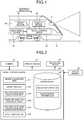
- FIG. 1 is a diagram illustrating a schematic configuration of a railway vehicle RV according to the present embodiment.
- the railway vehicle RV an example of the train
- the railway vehicle RV includes a camera 10, a travel control device 20, a recording device 30, a display device 40, and a speed sensor 50.
- the camera 10 is provided in the railway vehicle RV and is an example of an image capturing unit capable of capturing an area ahead (in an advancing direction) of the railway vehicle RV.
- an object objects 60, 61 in FIG. 3 , or the object 61 in FIG. 4 , which is able to specify a stop position of the railway vehicle RV, exists in the vicinity of a track in the advancing direction of the railway vehicle RV.
- the track collectively refers to structures (rails, ties, etc.) on a subgrade of a track of the train.
- the camera 10 is, for example, a stereo camera capable of determining a distance to the object.
- the travel control device 20 is a device that controls travel of the railway vehicle RV (details will be described later).
- the recording device 30 is a device that records various kinds of information used for travel control of the railway vehicle RV.
- the display device 40 is a device that displays various kinds of information and is, for example, a liquid crystal display (LCD).
- the speed sensor 50 is means for sensing a travel speed of the railway vehicle RV and is, for example, a wheel speed sensor to measure and output a rotational speed of wheels (an example of the speed information) of the railway vehicle RV.
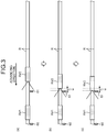
- FIG. 2 is a block diagram illustrating a functional configuration of the travel control device 20 of the railway vehicle RV according to the present embodiment.
- the travel control device 20 includes an image acquisition unit 201, a detection unit 202, a relative distance calculation unit 203, a speed information acquisition unit 204, a movement distance calculation unit 205, a travel control unit 206, and a storage unit 207.
- part of or all the components 201 to 206 are implemented when a central processing unit (CPU) and other processors of the railway vehicle RV execute software stored in the storage unit 207.
- CPU central processing unit
- part of or all the components 201 to 206 may be implemented by hardware, which is a circuit board such as a large scale integration (LSI), an application specific integrated circuit (ASIC), and a field programmable gate array (FPGA).
- LSI large scale integration
- ASIC application specific integrated circuit
- FPGA field programmable gate array
- the components 201 to 206 may be implemented by collaboration between the software executed by the processors and the hardware.
- the storage unit 207 includes nonvolatile recording media such as a read only memory (ROM), a flash memory, a hard disk drive (HDD), and an SD card, and volatile recording media such as a random access memory (RAM) and a register.
- ROM read only memory
- HDD hard disk drive
- SD card volatile recording media
- RAM random access memory
- the storage unit 207 stores various kinds of information such as computer programs executed by the processors of the railway vehicle RV (details will be described later).
- the image acquisition unit 201 obtains a captured image from the camera 10. For example, when the camera 10 is a stereo camera, the image acquisition unit 201 obtains a plurality of captured images by capturing areas ahead of the railway vehicle RV from different viewpoints. The image acquisition unit 201 successively obtains the captured images from the camera 10 in a preset cycle (such as a frame rate of the camera 10).
- the detection unit 202 detects the object in the captured images obtained by the image acquisition unit 201. More specifically, the object is, for example, a stop sign placed in the vicinity of the track at a station or a train shed.
- the relative distance calculation unit 203 calculates a relative distance between the railway vehicle RV and the object, based on a detection result of the object by the detection unit 202.
- the relative distance calculation unit 203 calculates the relative distance between the railway vehicle RV and the object, based on parallax of the object in the captured images obtained by image capturing with the camera 10.
- the relative distance calculation unit 203 successively calculates the relative distance each time the detection unit 202 detects the object.
- the relative distance calculation unit 203 may calculate the relative distance based on a dimension of the object in the captured images.
- the storage unit 207 stores object information including information indicative of an actual dimension of the object detected by the detection unit 202. Then, the relative distance calculation unit 203 calculates the relative distance based on the actual dimension of the object (a known object dimension) represented by the object information stored in the storage unit 207 and the dimension of the object in the captured images.
- the speed information acquisition unit 204 obtains, from the speed sensor 50, speed information of the railway vehicle RV.
- the movement distance calculation unit 205 calculates a movement distance of the railway vehicle RV, based on the speed information obtained by the speed information acquisition unit 204.
- the travel control unit 206 controls travel of the railway vehicle RV such that the railway vehicle RV stops at the stop position specified by the object.
- the control of the travel of the railway vehicle RV is performed based on: the relative distance calculated by the relative distance calculation unit 203 when the object is detected by the detection unit 202; and the movement distance calculated by the movement distance calculation unit 205 by changing control after a predetermined condition has been satisfied.
- the predetermined condition is, for example, any one among conditions (Condition 1) to (Condition 4) described below.
- the stop position information stored in the storage unit 207 is, for example, information including combinations of a plurality of the attributes of the railway vehicle RV with corresponding objects.
- the travel control unit 206 is able to specify the corresponding objects in accordance with the attributes of the railway vehicle RV and control travel of the railway vehicle RV.
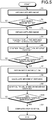
- FIG. 3 is a schematic diagram illustrating that the object leaves the captured image when the railway vehicle RV approaches the object 60, 61 in the present embodiment.
- FIG. 4 is a schematic diagram illustrating captured images in the present embodiment.
- the object 61 gradually increases in size in captured images captured by the camera 10 ( FIGS. 4(b) and (c) ).
- the railway vehicle RV2 stops at a time when the front end has reached a side of the object 61.
- FIG. 5 is a flowchart of the travel control by the travel control device 20 according to the present embodiment.
- the image acquisition unit 201 obtains a captured image from the camera 10.
- step S2 the detection unit 202 determines whether an object has been detected in the captured image obtained at step S1. In the case of "Yes”, the travel control proceeds to step S2, and, in the case of "No", the travel control returns to step S1.
- the image acquisition unit 201 obtains a captured image from the camera 10.
- the relative distance calculation unit 203 calculates a relative distance between the railway vehicle RV and the object, based on the captured image obtained at step S3.
- the travel control unit 206 controls travel of the railway vehicle RV, based on the relative distance calculated at step S4. That is, the travel control unit 206 controls travel of the railway vehicle RV so as to slow a speed as the railway vehicle RV approaches the object.
- step S6 the travel control unit 206 determines whether a predetermined condition (for example, one of Conditions 1 to 4 described above) has been satisfied. In the case of "Yes”, the travel control proceeds to step S7, and, in the case of "No", the travel control returns to step S3.
- a predetermined condition for example, one of Conditions 1 to 4 described above
- the speed information acquisition unit 204 obtains, from the speed sensor 50, speed information of the railway vehicle RV.
- the movement distance calculation unit 205 calculates a movement distance of the railway vehicle RV, based on the speed information obtained at step S7.
- the travel control unit 206 changes control and controls travel of the railway vehicle RV based on the movement distance calculated at step S8. That is, the travel control unit 206 controls travel of the railway vehicle RV so as to slow the speed as the railway vehicle RV approaches the object.
- step S10 the travel control unit 206 determines whether the railway vehicle RV has reached a predetermined position, based on, for example, the movement distance calculated at step S8. In the case of "Yes”, the travel control proceeds to step S11, and, in the case of "No", the travel control returns to step S7.
- the travel control unit 206 performs complete stop control of the railway vehicle RV.
- the travel control device 20 is capable of stopping the railway vehicle RV with high accuracy at the stop position specified by the object (for example, at an immediate side of the object). Functions and effects of the travel control device 20 according to the present embodiment will be described as compared with a conventional technique.
- a conventional technique for example, there is a control method of calculating a current position of a train with a global positioning system (GPS) or a global navigation satellite system (GNSS) so as to stop the train at a stop position specified by an object.
- GPS global positioning system
- GNSS global navigation satellite system
- Such a control method is disadvantageous in that an error of the stop position is as large as approximately 2 m.
- This control method is also disadvantageous in that it is necessary to prepare and store, as data, absolute position information of the object and speed control patterns in accordance with absolute positions of the railway vehicle, thereby increasing the cost.
- the travel control device 20 makes an error of the stop position significantly smaller than approximately 2 m (as small as several tens of cm, for example). Moreover, there is no need to prepare and store, as data, absolute position information of the object and speed control patterns in accordance with absolute positions of the railway vehicle, which can implement cost reduction.
- travel of the railway vehicle RV is first controlled based on the relative distance between the railway vehicle RV and the object that has been calculated based on the captured image.
- travel of the railway vehicle RV is controlled based on the movement distance calculated based on the speed information.
- the speed information acquisition unit 204 may obtain (calculate) speed information based on acceleration information obtained from an acceleration sensor (not illustrated) and information on a distance to the object that is obtained from a distance measurement device (not illustrated).
- the railway vehicle RV2 when no other railway vehicle (the railway vehicle RV1) exists ahead, the railway vehicle RV2 may simply perform stop control based on the furthest object 60, and when a second railway vehicle (the railway vehicle RV1) exists ahead, the railway vehicle RV2 may simply perform stop control based on the object 61 before the other railway vehicle.
- the detection unit 202 detects the second train that exists ahead of the railway vehicle RV2 in a captured image.
- the travel control unit 206 controls travel of the railway vehicle RV to stop the railway vehicle RV based on the object in a range that can keep a relative distance to the second train equal to or larger than a first threshold.
- a computer program executed by the travel control device 20 according to the present embodiment is provided in a form incorporated in a component such as the ROM in advance.
- the computer program executed by the travel control device 20 according to the present embodiment may be provided in a file of an installable format or an executable format that is recorded on a recording medium, such as a CD-ROM, a flexible disk (FD), a CD-R, and a digital versatile disc (DVD), which can be read by computers.
- the computer program executed by the travel control device 20 according to the present embodiment may be provided by storing the computer program in a computer connected to a network such as the Internet and downloading the computer program via the network.
- the computer program executed by the travel control device 20 according to the present embodiment may be provided or distributed via a network such as the Internet.
- the computer program executed by the travel control device 20 has a module configuration including the above-described components 201 to 206.
- the CPU reads the computer program from the ROM and executes the computer program so that the components are loaded on a main storage device, and that the components 201 to 206 are generated on the main storage device.
Landscapes
- Engineering & Computer Science (AREA)
- Mechanical Engineering (AREA)
- Power Engineering (AREA)
- Transportation (AREA)
- Life Sciences & Earth Sciences (AREA)
- Sustainable Development (AREA)
- Sustainable Energy (AREA)
- Electric Propulsion And Braking For Vehicles (AREA)
- Train Traffic Observation, Control, And Security (AREA)
Abstract
Description
- An embodiment of the present invention relates to a travel control device.
- Conventionally, in order to stop a train at a predetermined stop position, an object, such as a stop sign, is placed in the vicinity of a track in some cases. Various kinds of control methods have been developed to automatically stop the train at the stop position specified by the object in such cases.
- Patent Literature 1: Japanese Patent Application Laid-open No.
2018-19470 - However, in such conventional techniques, there is room for improvement in, for example, accuracy of the stop position of the train. Therefore, an object of the present embodiment is to stop a train with high accuracy at a stop position specified by an object.
- A travel control device of an embodiment includes a detection unit, a relative distance calculation unit, a speed information acquisition unit, a movement distance calculation unit, and a travel control unit. The detection unit detects an object existing in a vicinity of a track of a train and making a stop position of the train specifiable, the object being detected from a captured image obtained by capturing an area ahead of the train by an image capturing unit provided in the train. The relative distance calculation unit calculates a relative distance between the train and the object, based on a detection result of the object by the detection unit. The speed information acquisition unit obtains speed information of the train. The movement distance calculation unit calculates a movement distance of the train, based on the speed information obtained by the speed information acquisition unit. The travel control unit controls travel of the train such that the train stops at the stop position specified by the object. The control of the travel of the train is performed based on: the relative distance calculated by the relative distance calculation unit when the object is detected by the detection unit; and the movement distance calculated by the movement distance calculation unit by changing control after a predetermined condition is satisfied.
-
-
FIG. 1 is a diagram illustrating a schematic configuration of a railway vehicle according to the present embodiment. -
FIG. 2 is a block diagram illustrating a functional configuration of a travel control device of the railway vehicle according to the present embodiment. -
FIG. 3 is a schematic diagram illustrating a situation where an object is out of a captured image when the train approaches the object in the present embodiment. -
FIG. 4 is a schematic diagram illustrating captured images in the present embodiment. -
FIG. 5 is a flowchart of travel control by the travel control device according to the present embodiment. - Hereinafter, with reference to the accompanying drawings, description will be made on a railway vehicle to which a travel control device according to the present embodiment is applied.
-
FIG. 1 is a diagram illustrating a schematic configuration of a railway vehicle RV according to the present embodiment. As illustrated inFIG. 1 , the railway vehicle RV (an example of the train) according to the present embodiment includes acamera 10, atravel control device 20, arecording device 30, adisplay device 40, and aspeed sensor 50. - The
camera 10 is provided in the railway vehicle RV and is an example of an image capturing unit capable of capturing an area ahead (in an advancing direction) of the railway vehicle RV. Here, an object (objects FIG. 3 , or theobject 61 inFIG. 4 ), which is able to specify a stop position of the railway vehicle RV, exists in the vicinity of a track in the advancing direction of the railway vehicle RV. It should be noted that the track collectively refers to structures (rails, ties, etc.) on a subgrade of a track of the train. Thecamera 10 is, for example, a stereo camera capable of determining a distance to the object. - The
travel control device 20 is a device that controls travel of the railway vehicle RV (details will be described later). Therecording device 30 is a device that records various kinds of information used for travel control of the railway vehicle RV. Thedisplay device 40 is a device that displays various kinds of information and is, for example, a liquid crystal display (LCD). Thespeed sensor 50 is means for sensing a travel speed of the railway vehicle RV and is, for example, a wheel speed sensor to measure and output a rotational speed of wheels (an example of the speed information) of the railway vehicle RV. -
FIG. 2 is a block diagram illustrating a functional configuration of thetravel control device 20 of the railway vehicle RV according to the present embodiment. As illustrated inFIG. 2 , thetravel control device 20 includes animage acquisition unit 201, adetection unit 202, a relativedistance calculation unit 203, a speedinformation acquisition unit 204, a movementdistance calculation unit 205, atravel control unit 206, and astorage unit 207. - In the present embodiment, part of or all the
components 201 to 206 are implemented when a central processing unit (CPU) and other processors of the railway vehicle RV execute software stored in thestorage unit 207. - Alternatively, part of or all the
components 201 to 206 may be implemented by hardware, which is a circuit board such as a large scale integration (LSI), an application specific integrated circuit (ASIC), and a field programmable gate array (FPGA). Alternatively, thecomponents 201 to 206 may be implemented by collaboration between the software executed by the processors and the hardware. - The
storage unit 207 includes nonvolatile recording media such as a read only memory (ROM), a flash memory, a hard disk drive (HDD), and an SD card, and volatile recording media such as a random access memory (RAM) and a register. Thestorage unit 207 stores various kinds of information such as computer programs executed by the processors of the railway vehicle RV (details will be described later). - The
image acquisition unit 201 obtains a captured image from thecamera 10. For example, when thecamera 10 is a stereo camera, theimage acquisition unit 201 obtains a plurality of captured images by capturing areas ahead of the railway vehicle RV from different viewpoints. Theimage acquisition unit 201 successively obtains the captured images from thecamera 10 in a preset cycle (such as a frame rate of the camera 10). - The
detection unit 202 detects the object in the captured images obtained by theimage acquisition unit 201. More specifically, the object is, for example, a stop sign placed in the vicinity of the track at a station or a train shed. - The relative
distance calculation unit 203 calculates a relative distance between the railway vehicle RV and the object, based on a detection result of the object by thedetection unit 202. When thecamera 10 is a stereo camera, the relativedistance calculation unit 203 calculates the relative distance between the railway vehicle RV and the object, based on parallax of the object in the captured images obtained by image capturing with thecamera 10. The relativedistance calculation unit 203 successively calculates the relative distance each time thedetection unit 202 detects the object. - Alternatively, the relative
distance calculation unit 203 may calculate the relative distance based on a dimension of the object in the captured images. Specifically, thestorage unit 207 stores object information including information indicative of an actual dimension of the object detected by thedetection unit 202. Then, the relativedistance calculation unit 203 calculates the relative distance based on the actual dimension of the object (a known object dimension) represented by the object information stored in thestorage unit 207 and the dimension of the object in the captured images. - The speed
information acquisition unit 204 obtains, from thespeed sensor 50, speed information of the railway vehicle RV. - The movement
distance calculation unit 205 calculates a movement distance of the railway vehicle RV, based on the speed information obtained by the speedinformation acquisition unit 204. - The
travel control unit 206 controls travel of the railway vehicle RV such that the railway vehicle RV stops at the stop position specified by the object. The control of the travel of the railway vehicle RV is performed based on: the relative distance calculated by the relativedistance calculation unit 203 when the object is detected by thedetection unit 202; and the movement distance calculated by the movementdistance calculation unit 205 by changing control after a predetermined condition has been satisfied. - The predetermined condition is, for example, any one among conditions (Condition 1) to (Condition 4) described below.
- (Condition 1) The object has been out of a captured image.
- (Condition 2) The object has moved to a predetermined position (such as a lower left position as in
FIG. 3(c) ) in a captured image. - (Condition 3) The object has become a predetermined size (such as a size of the
object 61 inFIG. 3(c) ) or larger in a captured image. - (Condition 4) The relative distance calculated by the relative
distance calculation unit 203 has become a second threshold (30 m, for example) or smaller. - It should be noted that, for example, for each attribute of the railway vehicle RV (a model, the number of cars, a group of the railway vehicle RV), a corresponding object may be different. In such cases, the stop position information stored in the
storage unit 207 is, for example, information including combinations of a plurality of the attributes of the railway vehicle RV with corresponding objects. By referring to the stop position information stored in thestorage unit 207, thetravel control unit 206 is able to specify the corresponding objects in accordance with the attributes of the railway vehicle RV and control travel of the railway vehicle RV. - Next, referring to
FIG. 3 andFIG. 4 , description will be made on that the object leaves a captured image when the railway vehicle RV approaches theobject FIG. 3 is a schematic diagram illustrating that the object leaves the captured image when the railway vehicle RV approaches theobject FIG. 4 is a schematic diagram illustrating captured images in the present embodiment. - First, as illustrated in
FIG. 3(a) , when a railway vehicle RV2 traveling on rails R is away from theobject 61 by, for example, 30 m or farther, theobject 61 is captured within an image captured by the camera 10 (FIG. 4(a) ). It should be noted that a railway vehicle RV1 stopping near theobject 60 exists ahead of the railway vehicle RV2. - Thereafter, as the railway vehicle RV2 approaches the
object 61, theobject 61 gradually increases in size in captured images captured by the camera 10 (FIGS. 4(b) and (c) ). - Thereafter, as illustrated in
FIG. 3(b) , when a relative distance (distance w) between the railway vehicle RV2 and theobject 61 becomes, for example 30 m or smaller, theobject 61 has been out of a captured image captured by the camera 10 (FIG. 4(d) ). - Thereafter, as illustrated in
FIG. 3(c) , the railway vehicle RV2 stops at a time when the front end has reached a side of theobject 61. - Next, referring to
FIG. 5 , travel control by thetravel control device 20 will be described.FIG. 5 is a flowchart of the travel control by thetravel control device 20 according to the present embodiment. First, at step S1, theimage acquisition unit 201 obtains a captured image from thecamera 10. - Next, at step S2, the
detection unit 202 determines whether an object has been detected in the captured image obtained at step S1. In the case of "Yes", the travel control proceeds to step S2, and, in the case of "No", the travel control returns to step S1. - At step S3, the
image acquisition unit 201 obtains a captured image from thecamera 10. Next, at step S4, the relativedistance calculation unit 203 calculates a relative distance between the railway vehicle RV and the object, based on the captured image obtained at step S3. - Next, at step S5, the
travel control unit 206 controls travel of the railway vehicle RV, based on the relative distance calculated at step S4. That is, thetravel control unit 206 controls travel of the railway vehicle RV so as to slow a speed as the railway vehicle RV approaches the object. - Next, at step S6, the
travel control unit 206 determines whether a predetermined condition (for example, one ofConditions 1 to 4 described above) has been satisfied. In the case of "Yes", the travel control proceeds to step S7, and, in the case of "No", the travel control returns to step S3. - At step S7, the speed
information acquisition unit 204 obtains, from thespeed sensor 50, speed information of the railway vehicle RV. - Next, at step S8, the movement
distance calculation unit 205 calculates a movement distance of the railway vehicle RV, based on the speed information obtained at step S7. - Next, at step S9, in order to stop the railway vehicle RV at the stop position specified by the object, the
travel control unit 206 changes control and controls travel of the railway vehicle RV based on the movement distance calculated at step S8. That is, thetravel control unit 206 controls travel of the railway vehicle RV so as to slow the speed as the railway vehicle RV approaches the object. - Next, at step S10, the
travel control unit 206 determines whether the railway vehicle RV has reached a predetermined position, based on, for example, the movement distance calculated at step S8. In the case of "Yes", the travel control proceeds to step S11, and, in the case of "No", the travel control returns to step S7. - At step S11, the
travel control unit 206 performs complete stop control of the railway vehicle RV. - In this manner, the
travel control device 20 according to the present embodiment is capable of stopping the railway vehicle RV with high accuracy at the stop position specified by the object (for example, at an immediate side of the object). Functions and effects of thetravel control device 20 according to the present embodiment will be described as compared with a conventional technique. In the conventional technique, for example, there is a control method of calculating a current position of a train with a global positioning system (GPS) or a global navigation satellite system (GNSS) so as to stop the train at a stop position specified by an object. Such a control method is disadvantageous in that an error of the stop position is as large as approximately 2 m. This control method is also disadvantageous in that it is necessary to prepare and store, as data, absolute position information of the object and speed control patterns in accordance with absolute positions of the railway vehicle, thereby increasing the cost. - In contrast, the
travel control device 20 according to the present embodiment makes an error of the stop position significantly smaller than approximately 2 m (as small as several tens of cm, for example). Moreover, there is no need to prepare and store, as data, absolute position information of the object and speed control patterns in accordance with absolute positions of the railway vehicle, which can implement cost reduction. - In the conventional technique, for example, there is a control method of capturing an image of the object using a camera provided in the front end of the train and calculating a relative distance between the train and the object by image recognition so as to stop the train at the stop position. Such a control method is disadvantageous in that when the train approaches the object to some extent (30 m, for example), the object leaves a captured image, which may hinder subsequent stop control.
- In contrast, with the
travel control device 20 according to the present embodiment, after the object is detected in the captured image and until the predetermined condition is satisfied, travel of the railway vehicle RV is first controlled based on the relative distance between the railway vehicle RV and the object that has been calculated based on the captured image. After the predetermined condition (for example, one of the above-describedconditions 1 to 4) has been satisfied, travel of the railway vehicle RV is controlled based on the movement distance calculated based on the speed information. Thus, when the railway vehicle RV approaches the object to some extent (30 m, for example) and even though the object has left the captured image, accuracy of the stop position of the railway vehicle RV is not lowered. - Next, modifications of the
travel control device 20 will be described. Instead of obtaining the speed information from thespeed sensor 50, the speedinformation acquisition unit 204 may obtain (calculate) speed information based on acceleration information obtained from an acceleration sensor (not illustrated) and information on a distance to the object that is obtained from a distance measurement device (not illustrated). - As illustrated in
FIG. 3 , in a case where a plurality of the objects such as theobjects furthest object 60, and when a second railway vehicle (the railway vehicle RV1) exists ahead, the railway vehicle RV2 may simply perform stop control based on theobject 61 before the other railway vehicle. In such a case, thedetection unit 202 detects the second train that exists ahead of the railway vehicle RV2 in a captured image. When thedetection unit 202 detects the second train existing ahead of the railway vehicle RV2, thetravel control unit 206 controls travel of the railway vehicle RV to stop the railway vehicle RV based on the object in a range that can keep a relative distance to the second train equal to or larger than a first threshold. - This makes it possible to flexibly perform stop control of the railway vehicle RV depending on whether a second railway vehicle exists ahead.
- It should be noted that a computer program executed by the
travel control device 20 according to the present embodiment is provided in a form incorporated in a component such as the ROM in advance. The computer program executed by thetravel control device 20 according to the present embodiment may be provided in a file of an installable format or an executable format that is recorded on a recording medium, such as a CD-ROM, a flexible disk (FD), a CD-R, and a digital versatile disc (DVD), which can be read by computers. - Furthermore, the computer program executed by the
travel control device 20 according to the present embodiment may be provided by storing the computer program in a computer connected to a network such as the Internet and downloading the computer program via the network. The computer program executed by thetravel control device 20 according to the present embodiment may be provided or distributed via a network such as the Internet. - The computer program executed by the
travel control device 20 according to the present embodiment has a module configuration including the above-describedcomponents 201 to 206. As actual hardware, the CPU reads the computer program from the ROM and executes the computer program so that the components are loaded on a main storage device, and that thecomponents 201 to 206 are generated on the main storage device. - The embodiment of the present invention and the modifications that have been described heretofore are provided as examples and not intended to limit the scope of the invention. The novel embodiment and the modifications are implementable in other various modes and can be omitted, replaced, and changed in various manners without departing from the subject matter of the invention. The embodiment and the modifications are included in the scope and the subject matter of the invention, and also included in inventions recited in the claims and in their equal scope.
Claims (5)
- A travel control device comprising:a detection unit for detecting an object existing in a vicinity of a track of a train and making a stop position of the train specifiable, the object being detected from a captured image obtained by capturing an area ahead of the train by an image capturing unit provided in the train;a relative distance calculation unit for calculating a relative distance between the train and the object, based on a detection result of the object by the detection unit;a speed information acquisition unit for obtaining speed information of the train;a movement distance calculation unit for calculating a movement distance of the train, based on the speed information obtained by the speed information acquisition unit; anda travel control unit for controlling travel of the train such that the train stops at the stop position specified by the object, wherein the control of the travel of the train is performed based onthe relative distance calculated by the relative distance calculation unit when the object is detected by the detection unit, andthe movement distance calculated by the movement distance calculation unit by changing control after a predetermined condition is satisfied.
- The travel control device according to claim 1, wherein the speed information acquisition unit obtains the speed information based on at least one of: a rotational speed of wheels of the train obtained from a wheel speed sensor; acceleration information obtained from an acceleration sensor; and information on a distance to the object obtained by a distance measurement device.
- The travel control device according to claim 1, wherein
the detection unit detects a second train existing ahead of the train in the captured image, and,
the travel control unit controls, when the detection unit detects a second train existing ahead of the train, travel of the train such that the train stops in a state that a relative distance to the second train is equal to or larger than a first threshold. - The travel control device according to claim 1, wherein
the image capturing unit is a stereo camera, and
the relative distance calculation unit calculates the relative distance between the train and the object, based on parallax of the object in a plurality of the captured images obtained by image capturing using the stereo camera. - The travel control device according to claim 1, wherein the predetermined condition is one of conditions that:the object has been out of the captured image;the object has moved to a predetermined position in the captured image;the object has become a predetermined size or larger in the captured image; andthe relative distance calculated by the relative distance calculation unit has become a second threshold or smaller.
Applications Claiming Priority (2)
| Application Number | Priority Date | Filing Date | Title |
|---|---|---|---|
| JP2018125021A JP7123665B2 (en) | 2018-06-29 | 2018-06-29 | travel control device |
| PCT/JP2019/023749 WO2020004087A1 (en) | 2018-06-29 | 2019-06-14 | Travel control device |
Publications (2)
| Publication Number | Publication Date |
|---|---|
| EP3815955A1 true EP3815955A1 (en) | 2021-05-05 |
| EP3815955A4 EP3815955A4 (en) | 2022-03-16 |
Family
ID=68986489
Family Applications (1)
| Application Number | Title | Priority Date | Filing Date |
|---|---|---|---|
| EP19827088.6A Pending EP3815955A4 (en) | 2018-06-29 | 2019-06-14 | TRAVEL CONTROL DEVICE |
Country Status (5)
| Country | Link |
|---|---|
| EP (1) | EP3815955A4 (en) |
| JP (1) | JP7123665B2 (en) |
| CN (1) | CN112334357B (en) |
| SG (1) | SG11202012317TA (en) |
| WO (1) | WO2020004087A1 (en) |
Families Citing this family (2)
| Publication number | Priority date | Publication date | Assignee | Title |
|---|---|---|---|---|
| US10919546B1 (en) | 2020-04-22 | 2021-02-16 | Bnsf Railway Company | Systems and methods for detecting tanks in railway environments |
| JP2024063952A (en) * | 2022-10-27 | 2024-05-14 | 古河電気工業株式会社 | SUPPORT INFORMATION CREATION DEVICE, SUPPORT INFORMATION CREATION SYSTEM, SUPPORT INFORMATION CREATION METHOD, AND SUPPORT INFORMATION CREATION PROGRAM |
Family Cites Families (9)
| Publication number | Priority date | Publication date | Assignee | Title |
|---|---|---|---|---|
| JP5030983B2 (en) | 2009-02-10 | 2012-09-19 | 株式会社日立製作所 | Train stop detection system and train moving speed and position detection system |
| JP5759331B2 (en) * | 2011-09-30 | 2015-08-05 | 日本信号株式会社 | Train control system |
| DK3027482T3 (en) * | 2013-07-31 | 2021-12-20 | Rail Vision Ltd | SYSTEM AND PROCEDURE FOR IDENTIFICATION AND AVOIDANCE OF PREVENTION |
| JP6302994B2 (en) * | 2014-03-03 | 2018-03-28 | 株式会社日立製作所 | Signal system |
| JP2015182477A (en) * | 2014-03-20 | 2015-10-22 | 株式会社日立製作所 | Test apparatus and test method for train running and automatic train stop device with pattern |
| US10023162B2 (en) | 2014-09-05 | 2018-07-17 | Mitsubishi Electric Corporation | Automatic train operation system and brake control device |
| JP6511283B2 (en) * | 2015-02-12 | 2019-05-15 | 日立オートモティブシステムズ株式会社 | Object detection device |
| CN106184160B (en) * | 2016-07-19 | 2018-11-09 | 上海富欣智能交通控制有限公司 | Automatic train stop control method |
| JP6801995B2 (en) * | 2016-07-26 | 2020-12-16 | 株式会社日立製作所 | Train automatic stop control device and railway vehicle equipped with it |
-
2018
- 2018-06-29 JP JP2018125021A patent/JP7123665B2/en active Active
-
2019
- 2019-06-14 SG SG11202012317TA patent/SG11202012317TA/en unknown
- 2019-06-14 WO PCT/JP2019/023749 patent/WO2020004087A1/en not_active Ceased
- 2019-06-14 CN CN201980042962.4A patent/CN112334357B/en active Active
- 2019-06-14 EP EP19827088.6A patent/EP3815955A4/en active Pending
Also Published As
| Publication number | Publication date |
|---|---|
| WO2020004087A1 (en) | 2020-01-02 |
| CN112334357A (en) | 2021-02-05 |
| JP2020005464A (en) | 2020-01-09 |
| JP7123665B2 (en) | 2022-08-23 |
| EP3815955A4 (en) | 2022-03-16 |
| CN112334357B (en) | 2024-08-23 |
| SG11202012317TA (en) | 2021-01-28 |
Similar Documents
| Publication | Publication Date | Title |
|---|---|---|
| US10139832B2 (en) | Computer-assisted or autonomous driving with region-of-interest determination for traffic light analysis | |
| KR102918184B1 (en) | Object location confirmation system and method | |
| KR20110134633A (en) | Speed measuring device and measured speed compensation method | |
| CN112399942B (en) | Detection area database creation device | |
| JP2022514891A (en) | Systems and methods for automatic image labeling for supervised machine learning | |
| CN110431609A (en) | Vehicle Position Estimation Device | |
| US11971257B2 (en) | Method and apparatus with localization | |
| AU2020200802A1 (en) | Vehicle-mounted device and headway distance calculation method | |
| EP3872692A1 (en) | Compensation for vertical road curvature in road geometry estimation | |
| JP6813057B2 (en) | Visual odometry methods, devices and computer readable storage media | |
| CN112334357B (en) | Travel Controls | |
| US20180082581A1 (en) | Travel speed calculation device and travel speed calculation method | |
| JP2017054424A (en) | Video reference point determination system, video reference point determination method, and video reference point determination program | |
| CN116129378A (en) | Lane line detection method, device, equipment, vehicle and medium | |
| JP7210157B2 (en) | Fixed position stop control device | |
| JP7626194B2 (en) | Simulated road generation system, simulated road generation method and program | |
| JP2016085105A (en) | Moving body speed estimation apparatus, method, and program | |
| US11443619B2 (en) | Vehicle recognition apparatus and vehicle recognition method | |
| JP6955464B2 (en) | Vehicle position determination device | |
| AU2019203180B2 (en) | Vehicle recognition apparatus and vehicle recognition method | |
| US11267477B2 (en) | Device and method for estimating the attention level of a driver of a vehicle | |
| CN116222587A (en) | Position accuracy judging device, storage medium and judging method | |
| CN116391108A (en) | Road object positioning method | |
| JP5962331B2 (en) | Speed estimation apparatus and speed estimation method | |
| JP7701194B2 (en) | Information processing device, information processing method, and program |
Legal Events
| Date | Code | Title | Description |
|---|---|---|---|
| STAA | Information on the status of an ep patent application or granted ep patent |
Free format text: STATUS: THE INTERNATIONAL PUBLICATION HAS BEEN MADE |
|
| PUAI | Public reference made under article 153(3) epc to a published international application that has entered the european phase |
Free format text: ORIGINAL CODE: 0009012 |
|
| STAA | Information on the status of an ep patent application or granted ep patent |
Free format text: STATUS: REQUEST FOR EXAMINATION WAS MADE |
|
| 17P | Request for examination filed |
Effective date: 20201211 |
|
| AK | Designated contracting states |
Kind code of ref document: A1 Designated state(s): AL AT BE BG CH CY CZ DE DK EE ES FI FR GB GR HR HU IE IS IT LI LT LU LV MC MK MT NL NO PL PT RO RS SE SI SK SM TR |
|
| DAV | Request for validation of the european patent (deleted) | ||
| DAX | Request for extension of the european patent (deleted) | ||
| A4 | Supplementary search report drawn up and despatched |
Effective date: 20220211 |
|
| RIC1 | Information provided on ipc code assigned before grant |
Ipc: B60L 3/00 20190101ALI20220207BHEP Ipc: B61L 25/02 20060101ALI20220207BHEP Ipc: B60L 15/40 20060101AFI20220207BHEP |
|
| RAP1 | Party data changed (applicant data changed or rights of an application transferred) |
Owner name: KABUSHIKI KAISHA TOSHIBA |
|
| STAA | Information on the status of an ep patent application or granted ep patent |
Free format text: STATUS: EXAMINATION IS IN PROGRESS |
|
| 17Q | First examination report despatched |
Effective date: 20260414 |