EP3815850A1 - Flush mount tabletop for automatic cable tie tool - Google Patents
Flush mount tabletop for automatic cable tie tool Download PDFInfo
- Publication number
- EP3815850A1 EP3815850A1 EP20204799.9A EP20204799A EP3815850A1 EP 3815850 A1 EP3815850 A1 EP 3815850A1 EP 20204799 A EP20204799 A EP 20204799A EP 3815850 A1 EP3815850 A1 EP 3815850A1
- Authority
- EP
- European Patent Office
- Prior art keywords
- tool
- paddle
- cable tie
- automatic cable
- flush mount
- Prior art date
- Legal status (The legal status is an assumption and is not a legal conclusion. Google has not performed a legal analysis and makes no representation as to the accuracy of the status listed.)
- Granted
Links
Images






Classifications
-
- B—PERFORMING OPERATIONS; TRANSPORTING
- B25—HAND TOOLS; PORTABLE POWER-DRIVEN TOOLS; MANIPULATORS
- B25H—WORKSHOP EQUIPMENT, e.g. FOR MARKING-OUT WORK; STORAGE MEANS FOR WORKSHOPS
- B25H1/00—Work benches; Portable stands or supports for positioning portable tools or work to be operated on thereby
-
- B—PERFORMING OPERATIONS; TRANSPORTING
- B65—CONVEYING; PACKING; STORING; HANDLING THIN OR FILAMENTARY MATERIAL
- B65B—MACHINES, APPARATUS OR DEVICES FOR, OR METHODS OF, PACKAGING ARTICLES OR MATERIALS; UNPACKING
- B65B13/00—Bundling articles
- B65B13/02—Applying and securing binding material around articles or groups of articles, e.g. using strings, wires, strips, bands or tapes
- B65B13/025—Hand-held tools
- B65B13/027—Hand-held tools for applying straps having preformed connecting means, e.g. cable ties
-
- B—PERFORMING OPERATIONS; TRANSPORTING
- B25—HAND TOOLS; PORTABLE POWER-DRIVEN TOOLS; MANIPULATORS
- B25H—WORKSHOP EQUIPMENT, e.g. FOR MARKING-OUT WORK; STORAGE MEANS FOR WORKSHOPS
- B25H1/00—Work benches; Portable stands or supports for positioning portable tools or work to be operated on thereby
- B25H1/0021—Stands, supports or guiding devices for positioning portable tools or for securing them to the work
- B25H1/0042—Stands
- B25H1/005—Stands attached to a workbench
-
- B—PERFORMING OPERATIONS; TRANSPORTING
- B25—HAND TOOLS; PORTABLE POWER-DRIVEN TOOLS; MANIPULATORS
- B25H—WORKSHOP EQUIPMENT, e.g. FOR MARKING-OUT WORK; STORAGE MEANS FOR WORKSHOPS
- B25H1/00—Work benches; Portable stands or supports for positioning portable tools or work to be operated on thereby
- B25H1/02—Work benches; Portable stands or supports for positioning portable tools or work to be operated on thereby of table type
-
- B—PERFORMING OPERATIONS; TRANSPORTING
- B65—CONVEYING; PACKING; STORING; HANDLING THIN OR FILAMENTARY MATERIAL
- B65B—MACHINES, APPARATUS OR DEVICES FOR, OR METHODS OF, PACKAGING ARTICLES OR MATERIALS; UNPACKING
- B65B13/00—Bundling articles
- B65B13/02—Applying and securing binding material around articles or groups of articles, e.g. using strings, wires, strips, bands or tapes
- B65B13/025—Hand-held tools
-
- B—PERFORMING OPERATIONS; TRANSPORTING
- B65—CONVEYING; PACKING; STORING; HANDLING THIN OR FILAMENTARY MATERIAL
- B65B—MACHINES, APPARATUS OR DEVICES FOR, OR METHODS OF, PACKAGING ARTICLES OR MATERIALS; UNPACKING
- B65B27/00—Bundling particular articles presenting special problems using string, wire, or narrow tape or band; Baling fibrous material, e.g. peat, not otherwise provided for
- B65B27/10—Bundling rods, sticks, or like elongated objects
Definitions
- the present invention relates to an automatic cable tie tool, and more particularly to a flush mount tabletop fixture for an automatic cable tie tool.
- the present invention is directed to an assembly that mounts an automatic cable tie tool flush to a work surface.
- the flush mount assembly includes an overlay plate, a tool cage assembly, and a paddle assembly.
- the overlay plate is secured to a work surface.
- the tool cage is suspended from the overlay plate by an integrated insert plate.
- the tool cage holds the automatic cable tie tool enabling the jaws of the tool to protrude above the work surface.
- the paddle assembly is rotatably mounted to the insert plate. The paddle assembly activates the automatic cable tie tool.
- FIGS. 1-3 illustrate the flush mount tool fixture 70 of the present invention with an automatic cable tie tool 200 installed therein.
- the flush mount tool fixture 70 enables the top of the automatic cable tie tool 200 to protrude above a work surface 50.
- the automatic cable tie tool 200 is accessible for soft and ridged wire harness bundling using continuously molded cable ties.
- an operator actuates the tool by engaging a hand paddle 96 positioned alongside the open jaws 202, 204 of the installed automatic cable tie tool 200.
- the hand paddle improves the ergonomics of using the automatic cable tie tool 200 for long work durations.
- a ruler label may be referenced along both sides of the overlay plate for measuring distances relative to the center of the automatic cable tie tool 200.
- the flush mount tool fixture 70 is comprised of a tool cage 120 and an overlay plate assembly.
- FIG. 4 illustrates a work surface 50 with an overlay plate 60, a cover 62, and an insert plate 80 positioned above the work surface 50 to be installed therein.
- the tool cage 120 and automatic cable tie tool 200 are positioned below the work surface 50.
- the tool cage 120 is installed onto the insert plate 80 and positioned to hold the automatic cable tie tool 200 flush with the work surface 50.
- FIG. 5 illustrates the assembled flush mount tool fixture with the automatic cable tie tool removed.
- the overlay plate 60 is affixed to the insert plate 80 (obscured from view).
- the overlay plate 60 provides a large work surface on the table (see FIG. 1 ).
- a smooth transition between the overlay plate and the table aims to lessen product intrusion within the work area.
- the operator When not in use, the operator removes the automatic cable tie tool 200 individually, or the tool 200 and the tool cage 120 may be removed together from the insert plate 80.
- a cover 62 is installed over the open cavity. The cover 62 obscures the surface gaps in the flush mount tool fixture when the fixture is not in use.
- the actuation hand paddle 96 can be restrained by manually pushing the front face of the paddle until a ninety-degree arc is traveled. At this point the paddle 96 engages a latching slider 94 secured between the overlay plate 60 and the insert plate 80. The latching slider 94 locks the paddle 96 in a retracted position flush with the work surface 50. As a result, a flat work surface is created to restore the surface area used by the flush mount tool fixture 70 and the automatic cable tie tool 200.
- FIG. 6 is an exploded view of the flush mount tool fixture of the present invention.
- the tool cage 120 is positioned below the overlay plate 60 and the insert plate 80.
- the tool cage 120 includes a first side cage member 122 and a second side cage member 132.
- Each side cage member 122, 132 includes arms 128, 138, respectively, with guide bolts 130, 140 located at the distal ends of the arms 128, 138.
- the first side cage member 122 and second side cage member 132 also include front flanges 124, 134 with apertures 126, 136, respectively.
- the front flanges 124, 134 are secured to the front support block 142 and the front handle support block 146 by fasteners 144, 148 to form the front of the tool cage 120.
- a rear handle support block 150 is secured to the front handle support block 142 by rear block retaining thumb screws 152.
- the front support block 142, the front handle support block 146, and the rear handle support block 150 retain the automatic cable tie tool 200 in its
- the guide bolts 130, 140 at the distal ends of the arms 128, 138 of the first side cage member 122 and second side cage member 132 interact with guide slots 82 in the insert plate 80.
- the guide slots 82 guide the first side cage member 122 and the second side cage member 132 of the tool cage 120 into a position effectively fixing the tool cage 120 in place relative to the work surface 50.
- No mechanical fastener is required to affix the tool cage 120 to the insert plate 80.
- Alignment end stops 84 assist in aligning the tool cage 120 for insertion by limiting forward travel once the guide bolts 130, 140 align with the insert plate guide slots 82.
- the insert plate 80 retains the actuator 92, the tool cage 120, and the electronics enclosure 90.
- the insert plate 80 also includes a plurality of locating louvers 86 (see FIG. 6 ). The locating louvers 86 help align the insert plate 80 during installation onto a work surface 50.
- the electronics enclosure 90 is fastened to flanges 88 on the insert plate 80.
- the electronics enclosure 90 houses the electronic pneumatic valve as well as the PCB required to relay optical limit switch signals to the system via a parallel port.
- a standard NPT male quick connect fitting accepts air at forty (40) PSI from the primary airline leading to the PAT system. That air is channeled into the electronic valve and exits through a 3/8" quick connector.
- a grommet covers a slotted path for external sensor conductors to enter the electronics enclosure 90 and provide feedback on the position of the paddle 96.
- a linear actuator 92 is mounted onto the second side cage member 132.
- the linear actuator 92 is fed air from the 3/8" quick connector.
- a pneumatic cylinder receives this air thus pivoting the actuator arm which strikes the PAT tool's trigger, engaging the jaws and allowing the PAT system to feed the cable tie onto a work piece, such as a cable bundle.
- An internal spring retracts the actuator arm once air pressure is removed from the air line by the valve.
- FIG. 7 illustrates the insert plate 80 and actuation hand paddle 96 in an upright position.
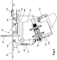
- FIG. 8 illustrates the tool cage 120 secured to the insert plate 80 and the actuation hand paddle 96 in the upright position.
- FIGS. 9-12 further illustrate the actuation hand paddle assembly.
- the paddle assembly 95 includes a paddle 96 which is mechanically fastened to a pair of mounting blocks 98.
- the paddle 96 is actuated by either an operator's hand or by the workpiece and returns to its start position via a torsion spring 100.
- the mounting blocks 98 straddle a slot on the right-hand side flange of the insert plate 80.
- Two nylon bushings 102 fit within the opening of the slot and align the mounting blocks 98.
- the actuation sensor is an optical limit switch 104 and is fastened to the exterior mounting block 98 by the screws that retain the two blocks against the insert plate flange 88.
- the paddle 96 is designed to travel throughout a full ninety-degree arc.
- the paddle 96 will engage the pneumatic cylinder throughout a sixty-degree arc as established by the optical sensor blade 106.
- the paddle 96 can travel through fifteen degrees of motion before the blade blocks the optical beam and will continue to actuate if the blade inhabits the optical sensor slot.
- the blade 106 will disengage from the sensor and allow the paddle 96 to be latched in a horizontal orientation via the paddle latch 108 engaging the release slider 94 on the overlay plate 60 and insert plate 80.
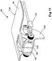
- FIG. 11 illustrates the paddle assembly 95 with the paddle 96 in the horizontal orientation. Moving the release slider 94 away from the paddle 96 will disengage the paddle latch 108. Once released, the paddle 96 flips up to a vertical position, ready for operation. The forward travel as well as the actuation resistance and "reset” is accomplished by the torsion spring 100. Slots integrated within the insert plate 80 enable the paddle to cover overlay openings when in the folded, latched horizontal orientation.
- FIGS. 13-16 illustrate the flush mount tool fixture and the automatic cable tie tool 200 of the present invention prior to use.
- FIGS. 17-20 illustrate flush mount tool fixture and the automatic cable tie tool 200 in use.
- the tool cage 120 may be installed in the slots 82 in the insert plate 80 with the automatic cable tie tool 200 ( FIGS. 13-14 ) or the tool cage 120 may be installed onto the slots 82 in the insert plate 80 individually ( FIG. 15 ). If the tool cage 120 is installed individually, the automatic cable tie tool 200 and rear handle support block 150 are secured to the tool cage 120 after it is mounted to the insert plate 80. Additionally, the cover 62 is removed from the overlay plate 60 prior to installing the automatic cable tie tool 200.
- FIG. 16 illustrates the flush mount tool fixture and automatic cable tie tool 200 in an operational position ready to install cable ties.
- the cover 62 has been removed and the top of the automatic cable tie tool 200 extends above the overlay plate 60.
- the hand paddle 96 is also in an upright position, ready to be activated.
- FIGS. 17-18 illustrates a work piece 210 positioned under the upper jaw 202 of the automatic cable tie tool 200.
- the paddle 96 has been actuated and the lower jaw 204 and upper jaw 202 have closed around the work piece 210 to install the cable tie.
- the paddle 96 is actuated by either a hand or the work piece 210 engaging or pushing the paddle 96 backwards.
- the hand paddle 96 and flush mount of the automatic cable tie tool 200 of the present invention provides an ergonomic improvement over prior bench mount tools with foot activation pedals.
Landscapes
- Engineering & Computer Science (AREA)
- Mechanical Engineering (AREA)
- Basic Packing Technique (AREA)
Abstract
Description
- This application claims benefit to
U.S. Provisional Patent Application No. 62/927,730, filed on October 30, 2019 - The present invention relates to an automatic cable tie tool, and more particularly to a flush mount tabletop fixture for an automatic cable tie tool.
- Automatic cable tie tool systems are well known in the art. Productivity is critical when it comes to high-volume harnessing, assembly, fastening, and packaging applications using automatic cable tie tool systems. To remain competitive, manufacturers are faced with the constant struggle to increase throughput, reduce lead times, and meet customer expectations. Panduit Corp.'s PAT 4.0 Automatic Cable Tie Installation System addresses these challenges by introducing a series of features and functionality to transform wire bundling and assembly. The PAT 4.0 Automatic Cable Tie Installation System includes a bench mount feature that is activated by a foot pedal assembly while the current tool meets expectations for wire bundling, it is now desirable to provide an automatic cable tie installation system with an improved flush bench mount fixture including a hand paddle for activation.
- The present invention is directed to an assembly that mounts an automatic cable tie tool flush to a work surface. The flush mount assembly includes an overlay plate, a tool cage assembly, and a paddle assembly. The overlay plate is secured to a work surface. The tool cage is suspended from the overlay plate by an integrated insert plate. The tool cage holds the automatic cable tie tool enabling the jaws of the tool to protrude above the work surface. The paddle assembly is rotatably mounted to the insert plate. The paddle assembly activates the automatic cable tie tool.
-
-
FIG. 1 is a perspective view of the flush mount tabletop fixture for an automatic cable tie tool of the claimed invention. -
FIG. 2 is a top perspective view of the flush mount tabletop fixture and automatic cable tie tool ofFIG. 1 . -
FIG. 3 is a bottom perspective view of the flush mount tabletop fixture and automatic cable tie tool ofFIG. 2 . -
FIG. 4 is a partially exploded view of the flush mount tabletop fixture and automatic cable tie tool ofFIG. 1 . -
FIG. 5 is a perspective view of the flush mount tabletop fixture ofFIG. 1 . -
FIG. 6 is an exploded view of the flush mount tabletop fixture ofFIG. 5 . -
FIG. 7 is a perspective view of the insert plate of the flush mount tabletop ofFIG. 5 . -
FIG. 8 is a side view of the insert plate ofFIG. 7 with the tool cage attached thereto. -
FIG. 9 is a rear perspective view of the paddle assembly that is installed onto the insert plate ofFIG. 7 . -
FIG. 10 is a top view of the paddle assembly ofFIG. 9 . -
FIG. 11 is a front perspective view of the paddle assembly ofFIG. 9 with the paddle in a folded position. -
FIG. 12 is a front perspective view of the paddle assembly ofFIG. 9 . -
FIG. 13 is a partially exploded perspective view of the automatic cable tie tool and tool cage, positioned to be inserted in the flush mount tabletop fixture ofFIG. 5 . -
FIG. 14 is a bottom partially exploded perspective view of the automatic cable tie tool and tool cage, positioned to be inserted in the flush mount tabletop fixture ofFIG. 13 . -
FIG. 15 is a bottom partially exploded perspective view of the automatic cable tie tool, positioned to be inserted into the tool cage, mounted to the flush mount tabletop fixture ofFIG. 11 . -
FIG. 16 is a top rear perspective view of the flush mount tabletop fixture and automatic cable tie tool ofFIG. 2 . -
FIG. 17 is a perspective view of the flush mount tabletop fixture and automatic cable tie tool ofFIG. 16 , with a workpiece positioned within the tool. -
FIG. 18 is a side view of the flush mount tabletop fixture and automatic cable tie tool ofFIG. 17 , with a workpiece positioned within the tool. -
FIG. 19 is a perspective view of the flush mount tabletop fixture and automatic cable tie tool, with the jaws of the tool around a workpiece. -
FIG. 20 is a side view of the flush mount tabletop fixture and automatic cable tie tool ofFIG. 19 , with a workpiece positioned within the tool. - The present invention is directed to a flush mount tool fixture that suspends an automatic cable tie
handheld tool 200 underneath awork surface 50.FIGS. 1-3 illustrate the flushmount tool fixture 70 of the present invention with an automaticcable tie tool 200 installed therein. The flushmount tool fixture 70 enables the top of the automaticcable tie tool 200 to protrude above awork surface 50. The automaticcable tie tool 200 is accessible for soft and ridged wire harness bundling using continuously molded cable ties. As described below, an operator actuates the tool by engaging ahand paddle 96 positioned alongside theopen jaws cable tie tool 200. The hand paddle improves the ergonomics of using the automaticcable tie tool 200 for long work durations. If desired, a ruler label may be referenced along both sides of the overlay plate for measuring distances relative to the center of the automaticcable tie tool 200. - The flush
mount tool fixture 70 is comprised of atool cage 120 and an overlay plate assembly.FIG. 4 illustrates awork surface 50 with anoverlay plate 60, acover 62, and aninsert plate 80 positioned above thework surface 50 to be installed therein. The tool cage 120 and automaticcable tie tool 200 are positioned below thework surface 50. As discussed below, thetool cage 120 is installed onto theinsert plate 80 and positioned to hold the automaticcable tie tool 200 flush with thework surface 50. -
FIG. 5 illustrates the assembled flush mount tool fixture with the automatic cable tie tool removed. Theoverlay plate 60 is affixed to the insert plate 80 (obscured from view). Theoverlay plate 60 provides a large work surface on the table (seeFIG. 1 ). A smooth transition between the overlay plate and the table aims to lessen product intrusion within the work area. - When not in use, the operator removes the automatic
cable tie tool 200 individually, or thetool 200 and thetool cage 120 may be removed together from theinsert plate 80. As illustrated inFIG. 5 , acover 62 is installed over the open cavity. Thecover 62 obscures the surface gaps in the flush mount tool fixture when the fixture is not in use. Theactuation hand paddle 96 can be restrained by manually pushing the front face of the paddle until a ninety-degree arc is traveled. At this point thepaddle 96 engages alatching slider 94 secured between theoverlay plate 60 and theinsert plate 80. Thelatching slider 94 locks thepaddle 96 in a retracted position flush with thework surface 50. As a result, a flat work surface is created to restore the surface area used by the flushmount tool fixture 70 and the automaticcable tie tool 200. -
FIG. 6 is an exploded view of the flush mount tool fixture of the present invention. Thetool cage 120 is positioned below theoverlay plate 60 and theinsert plate 80. Thetool cage 120 includes a firstside cage member 122 and a secondside cage member 132. Eachside cage member arms guide bolts arms side cage member 122 and secondside cage member 132 also includefront flanges apertures front flanges front support block 142 and the front handle support block 146 byfasteners tool cage 120. A rear handle support block 150 is secured to the front handle support block 142 by rear block retaining thumb screws 152. Thefront support block 142, the fronthandle support block 146, and the rear handle support block 150 retain the automaticcable tie tool 200 in its desired position. - The
guide bolts arms side cage member 122 and secondside cage member 132 interact withguide slots 82 in theinsert plate 80. Theguide slots 82 guide the firstside cage member 122 and the secondside cage member 132 of thetool cage 120 into a position effectively fixing thetool cage 120 in place relative to thework surface 50. No mechanical fastener is required to affix thetool cage 120 to theinsert plate 80. Alignment end stops 84 (seeFIG. 8 ) assist in aligning thetool cage 120 for insertion by limiting forward travel once theguide bolts plate guide slots 82. - The
insert plate 80 retains theactuator 92, thetool cage 120, and theelectronics enclosure 90. Theinsert plate 80 also includes a plurality of locating louvers 86 (seeFIG. 6 ). The locatinglouvers 86 help align theinsert plate 80 during installation onto awork surface 50. - The
electronics enclosure 90 is fastened toflanges 88 on theinsert plate 80. Theelectronics enclosure 90 houses the electronic pneumatic valve as well as the PCB required to relay optical limit switch signals to the system via a parallel port. A standard NPT male quick connect fitting accepts air at forty (40) PSI from the primary airline leading to the PAT system. That air is channeled into the electronic valve and exits through a 3/8" quick connector. A grommet covers a slotted path for external sensor conductors to enter theelectronics enclosure 90 and provide feedback on the position of thepaddle 96. - A
linear actuator 92 is mounted onto the secondside cage member 132. Thelinear actuator 92 is fed air from the 3/8" quick connector. A pneumatic cylinder receives this air thus pivoting the actuator arm which strikes the PAT tool's trigger, engaging the jaws and allowing the PAT system to feed the cable tie onto a work piece, such as a cable bundle. An internal spring retracts the actuator arm once air pressure is removed from the air line by the valve. -
FIG. 7 illustrates theinsert plate 80 andactuation hand paddle 96 in an upright position.FIG. 8 illustrates thetool cage 120 secured to theinsert plate 80 and theactuation hand paddle 96 in the upright position. -
FIGS. 9-12 further illustrate the actuation hand paddle assembly. Thepaddle assembly 95 includes apaddle 96 which is mechanically fastened to a pair of mountingblocks 98. Thepaddle 96 is actuated by either an operator's hand or by the workpiece and returns to its start position via atorsion spring 100. The mounting blocks 98 straddle a slot on the right-hand side flange of theinsert plate 80. Twonylon bushings 102 fit within the opening of the slot and align the mounting blocks 98. The actuation sensor is anoptical limit switch 104 and is fastened to theexterior mounting block 98 by the screws that retain the two blocks against theinsert plate flange 88. - The
paddle 96 is designed to travel throughout a full ninety-degree arc. Thepaddle 96 will engage the pneumatic cylinder throughout a sixty-degree arc as established by theoptical sensor blade 106. Thepaddle 96 can travel through fifteen degrees of motion before the blade blocks the optical beam and will continue to actuate if the blade inhabits the optical sensor slot. As thepaddle 96 approaches horizontal, theblade 106 will disengage from the sensor and allow thepaddle 96 to be latched in a horizontal orientation via thepaddle latch 108 engaging therelease slider 94 on theoverlay plate 60 and insertplate 80. -
FIG. 11 illustrates thepaddle assembly 95 with thepaddle 96 in the horizontal orientation. Moving therelease slider 94 away from thepaddle 96 will disengage thepaddle latch 108. Once released, thepaddle 96 flips up to a vertical position, ready for operation. The forward travel as well as the actuation resistance and "reset" is accomplished by thetorsion spring 100. Slots integrated within theinsert plate 80 enable the paddle to cover overlay openings when in the folded, latched horizontal orientation. -
FIGS. 13-16 illustrate the flush mount tool fixture and the automaticcable tie tool 200 of the present invention prior to use.FIGS. 17-20 illustrate flush mount tool fixture and the automaticcable tie tool 200 in use. As discussed above, thetool cage 120 may be installed in theslots 82 in theinsert plate 80 with the automatic cable tie tool 200 (FIGS. 13-14 ) or thetool cage 120 may be installed onto theslots 82 in theinsert plate 80 individually (FIG. 15 ). If thetool cage 120 is installed individually, the automaticcable tie tool 200 and rear handle support block 150 are secured to thetool cage 120 after it is mounted to theinsert plate 80. Additionally, thecover 62 is removed from theoverlay plate 60 prior to installing the automaticcable tie tool 200. -
FIG. 16 illustrates the flush mount tool fixture and automaticcable tie tool 200 in an operational position ready to install cable ties. Thecover 62 has been removed and the top of the automaticcable tie tool 200 extends above theoverlay plate 60. Thehand paddle 96 is also in an upright position, ready to be activated. -
FIGS. 17-18 illustrates awork piece 210 positioned under theupper jaw 202 of the automaticcable tie tool 200. As illustrated inFIGS. 19-20 , thepaddle 96 has been actuated and thelower jaw 204 andupper jaw 202 have closed around thework piece 210 to install the cable tie. As discussed above, thepaddle 96 is actuated by either a hand or thework piece 210 engaging or pushing thepaddle 96 backwards. - The
hand paddle 96 and flush mount of the automaticcable tie tool 200 of the present invention provides an ergonomic improvement over prior bench mount tools with foot activation pedals. - Also disclosed herein are the following numbered clauses:
- 1. An automatic cable tie tool assembly flush mounted to a work surface, the automatic cable tie tool assembly comprising:
- an automatic cable tie tool,
- an overlay plate and an insert plate secured to the work surface;
a tool cage for holding the automatic cable tie tool, the tool cage is suspended from the insert plate for enabling a top of the automatic cable tie tool to protrude above the work surface; and a paddle assembly to activate the automatic cable tie tool, the paddle assembly is rotatably mounted to the insert plate.
- 2. The automatic cable tie tool assembly of clause 1, wherein the insert plate has an opening and guide slots located at each side of the opening, the guide slots are accessible from the bottom of the insert plate for receiving the tool cage.
- 3. The automatic cable tie tool assembly of
clause 1 or 2, wherein the tool cage has a first side cage member with arms and a second side cage member with arms, guide bolts are located at the distal ends of the arms of the first side cage member and at the distal ends of the arms of the second side cage member. - 4. The automatic cable tie tool assembly of any preceding clause, wherein the insert plate has an opening and guide slots located at each side of the opening, wherein the guide bolts extending from the arms of the first cage member and the guide bolts extending from the arms of the second cage member engage and travel along the guide slots for positioning the tool cage.
- 5. The automatic cable tie tool assembly of any preceding clause, wherein the first side cage member and the second side cage member include front flanges; a front support block and a front handle support block are secured to the front flanges by fasteners; and a rear handle support block is secured to the front handle support block by fasteners, whereby the front support block, the front handle support block, and the rear handle support block retain the automatic cable tie tool in position in the tool cage.
- 6. The automatic cable tie tool assembly of any preceding clause, wherein the paddle assembly having a paddle with a paddle latch;
a pair of mounting blocks mechanically fastened to the paddle, the mounting blocks are positioned within a slot on the insert plate;
an optical limit switch fastened to one of the mounting blocks;
a torsion spring; and
a sensor blade for controlling the actuation of the paddle. - 7. The automatic cable tie tool assembly of any preceding clause, wherein when the paddle is horizontal the sensor blade disengages and the paddle is latched in a horizontal orientation by the paddle latch engaging a release slider positioned between the overlay plate and the insert plate, whereby sliding the release slider disengages the paddle latch enabling the paddle to return to a vertical position ready for operation.
- 8. The automatic cable tie tool assembly of any preceding clause, wherein the overlay plate covers the insert plate.
- Furthermore, while the preferred embodiments of the present invention have been shown and described, it will be obvious to those skilled in the art that changes, and modifications may be made without departing from the teaching of the invention. The matter set forth in the foregoing description and accompanying drawings is offered by way of illustration only and not as limitation. The actual scope of the invention is intended to be defined in the following claims when viewed in their proper perspective based on the prior art.
Claims (13)
- A flush mount assembly for mounting an automatic cable tie tool to a work surface, the flush mount assembly comprising:an overlay plate and an insert plate secured to the work surface;a tool cage for holding the automatic cable tie tool, the tool cage is suspended from the insert plate for enabling a top of the automatic cable tie tool to protrude above the work surface; anda paddle assembly for activating the automatic cable tie tool, the paddle assembly is rotatably mounted to the insert plate.
- The flush mount assembly of claim 1, wherein the insert plate has an opening and guide slots located at each side of the opening, the guide slots are accessible from the bottom of the insert plate for receiving the tool cage.
- The flush mount assembly of claim 1 or 2, further comprising a release slider for securing the paddle assembly in a retracted position flush with the work surface.
- The flush mount assembly of any preceding claim, wherein the tool cage has a first side cage member with arms and a second side cage member with arms, guide bolts are located at the distal ends of the arms of the first side cage member and at the distal ends of the arms of the second side cage member.
- The flush mount assembly of any of claims 2 to 4, wherein the insert plate has an opening and guide slots located at each side of the opening, wherein the guide slots receive the first side cage member and the second side cage member.
- The flush mount assembly of claim 5, wherein the guide bolts extending from the arms of the first cage member and the guide bolts extending from the arms of the second cage member engage and travel along the guide slots for positioning the tool cage.
- The flush mount assembly of any of claims 4 to 6, wherein the first side cage member and the second side cage member include front flanges; a front support block and a front handle support block are secured to the front flanges by fasteners; and a rear handle support block is secured to the front handle support block by fasteners, whereby the front support block, the front handle support block, and the rear handle support block retain the automatic cable tie tool in position in the tool cage.
- The flush mount assembly of any preceding claim, wherein the paddle assembly having a paddle with a paddle latch;
a pair of mounting blocks mechanically fastened to the paddle, the mounting blocks are positioned within a slot on the insert plate;
an optical limit switch fastened to one of the mounting blocks;
a torsion spring; and
a sensor blade for controlling the actuation of the paddle. - The flush mount assembly of claim 8, wherein when the paddle is horizontal the sensor blade disengages and the paddle is latched in a horizontal orientation by the paddle latch engaging a release slider positioned between the overlay plate and the insert plate, whereby sliding the release slider disengages the paddle latch enabling the paddle to return to a vertical position ready for operation.
- The flush mount assembly of any preceding claim, wherein the overlay plate covers the insert plate.
- The flush mount assembly of any preceding claim, wherein the overlay plate having a ruler label for measuring distances relative to the automatic cable tie tool installed in the tool cage.
- The flush mount assembly of any preceding claim, further comprising a cover installed over openings within the overlay plate.
- An automatic cable tie tool assembly flush mounted to a work surface, the automatic cable tie tool assembly comprising:an automatic cable tie tool, andthe flush mount assembly of any preceding claim.
Applications Claiming Priority (2)
| Application Number | Priority Date | Filing Date | Title |
|---|---|---|---|
| US201962927730P | 2019-10-30 | 2019-10-30 | |
| US17/080,147 US11866207B2 (en) | 2019-10-30 | 2020-10-26 | Flush mount tabletop for automatic cable tie tool |
Publications (2)
| Publication Number | Publication Date |
|---|---|
| EP3815850A1 true EP3815850A1 (en) | 2021-05-05 |
| EP3815850B1 EP3815850B1 (en) | 2022-04-20 |
Family
ID=73039949
Family Applications (1)
| Application Number | Title | Priority Date | Filing Date |
|---|---|---|---|
| EP20204799.9A Active EP3815850B1 (en) | 2019-10-30 | 2020-10-29 | Flush mount tabletop for automatic cable tie tool |
Country Status (2)
| Country | Link |
|---|---|
| US (1) | US11866207B2 (en) |
| EP (1) | EP3815850B1 (en) |
Families Citing this family (1)
| Publication number | Priority date | Publication date | Assignee | Title |
|---|---|---|---|---|
| US11866207B2 (en) * | 2019-10-30 | 2024-01-09 | Panduit Corp. | Flush mount tabletop for automatic cable tie tool |
Citations (1)
| Publication number | Priority date | Publication date | Assignee | Title |
|---|---|---|---|---|
| US6321797B1 (en) * | 2000-05-19 | 2001-11-27 | Thomas & Betts International, Inc. | Bench mount apparatus for remote tool head |
Family Cites Families (25)
| Publication number | Priority date | Publication date | Assignee | Title |
|---|---|---|---|---|
| US2401511A (en) * | 1943-11-08 | 1946-06-04 | Pabst Brewing Co | Preheater for bottle caps |
| US3946769A (en) | 1974-03-12 | 1976-03-30 | Panduit Corporation | Automatic cable tie installation tool |
| US3976108A (en) | 1974-03-12 | 1976-08-24 | Panduit Corporation | Automatic cable tie installation tool |
| US4495972A (en) | 1980-02-27 | 1985-01-29 | Bowthorpe-Hellermann Limited | Automatic tie gun |
| US4483573A (en) * | 1982-07-09 | 1984-11-20 | Keller David L | Tool adapter for working table top storage cabinet |
| US4790225A (en) | 1982-11-24 | 1988-12-13 | Panduit Corp. | Dispenser of discrete cable ties provided on a continuous ribbon of cable ties |
| US5205308A (en) | 1991-09-03 | 1993-04-27 | Kendall Gloria B | Protection apparatus for infants |
| DE29617652U1 (en) | 1996-10-10 | 1998-02-12 | Paul Hellermann GmbH, 25421 Pinneberg | Cable tie tool |
| US5722466A (en) | 1997-01-13 | 1998-03-03 | Levin; Robert F. | Cable tie installation tool |
| AU728803B2 (en) | 1997-07-29 | 2001-01-18 | Thomas & Betts International, Inc. | Improved cable tie dispensing apparatus |
| US6112499A (en) | 1999-01-19 | 2000-09-05 | Hellermanntyton Corporation | Bag closure apparatus |
| US6267152B1 (en) | 2000-02-18 | 2001-07-31 | Wisconsin Label Corporation | Hang tag and method of applying hang tag to an elongated object |
| US6279620B1 (en) | 2000-05-19 | 2001-08-28 | Thomas & Betts International | Tool head for automatic cable tie installation system |
| US6508281B1 (en) * | 2001-07-19 | 2003-01-21 | Tian Wang Wang | Adjustable and extendible platform for working table |
| JP4585806B2 (en) | 2004-07-26 | 2010-11-24 | ヘラマンタイトン株式会社 | Bundling device with bundling waste recovery device |
| US8006596B2 (en) | 2005-03-11 | 2011-08-30 | Walter Meier (Manufacturing) Inc. | Cutting tool and parts and accessories therefor |
| JP4820634B2 (en) | 2005-12-05 | 2011-11-24 | ヘラマンタイトン株式会社 | External drive type bundling tool and manual driving type bundling device |
| JP4796870B2 (en) | 2006-03-06 | 2011-10-19 | ヘラマンタイトン株式会社 | Bundling tool drive human power device |
| JP4928806B2 (en) | 2006-03-06 | 2012-05-09 | ヘラマンタイトン株式会社 | Artificial drive type binding tool |
| EP3024621B1 (en) * | 2013-07-23 | 2020-10-14 | Safran Seats USA LLC | Adaptive manufacturing table |
| US10092968B2 (en) * | 2013-11-01 | 2018-10-09 | Sawstop Holding Llc | Table saws |
| FR3072080B1 (en) | 2017-10-09 | 2019-11-01 | Hellermanntyton Gmbh | MANUAL AUTOMATIC APPARATUS FOR INSTALLING CLAMPS |
| CN117944934A (en) | 2018-08-27 | 2024-04-30 | 深圳市施威德自动化科技有限公司 | A tensioning mechanism with floating center distance for an automatic cable tie tool |
| US11866207B2 (en) * | 2019-10-30 | 2024-01-09 | Panduit Corp. | Flush mount tabletop for automatic cable tie tool |
| US11040406B1 (en) * | 2020-01-15 | 2021-06-22 | Douglas Young | Saw slide device |
-
2020
- 2020-10-26 US US17/080,147 patent/US11866207B2/en active Active
- 2020-10-29 EP EP20204799.9A patent/EP3815850B1/en active Active
Patent Citations (1)
| Publication number | Priority date | Publication date | Assignee | Title |
|---|---|---|---|---|
| US6321797B1 (en) * | 2000-05-19 | 2001-11-27 | Thomas & Betts International, Inc. | Bench mount apparatus for remote tool head |
Non-Patent Citations (1)
| Title |
|---|
| KINGSING: "Automatic Nylon Cable Tie Tying & Bundling Machine", YOUTUBE, 23 December 2018 (2018-12-23), pages 1 pp., XP054981458, Retrieved from the Internet <URL:https://www.youtube.com/watch?v=VooM_dzj1TQ> [retrieved on 20210224] * |
Also Published As
| Publication number | Publication date |
|---|---|
| US11866207B2 (en) | 2024-01-09 |
| US20210130017A1 (en) | 2021-05-06 |
| EP3815850B1 (en) | 2022-04-20 |
Similar Documents
| Publication | Publication Date | Title |
|---|---|---|
| US12257639B2 (en) | Miter saw | |
| US8763260B2 (en) | Modular saw | |
| US5815931A (en) | Cutting guide for controlling the direction and cut of a hand held power cutting tool | |
| US9592623B2 (en) | Rip fence having dual adjustment for a power tool | |
| US20080172891A1 (en) | Hand-held circular saw | |
| EP2156930A2 (en) | Method and apparatus for automatically adjusting a miter saw fence | |
| CA2453205A1 (en) | Clamping arrangement for receiving a saw blade in multiple orientations | |
| EP3815850B1 (en) | Flush mount tabletop for automatic cable tie tool | |
| CN220838218U (en) | Shearing and cutting tool | |
| US12365081B2 (en) | Guide rail for guiding a hand-held power tool | |
| CN101668607A (en) | Mobile manual cutting machine having movable cutter | |
| US7516552B2 (en) | Guide and portable cutting tool provided therewith | |
| JPS59501542A (en) | Swing saw for cutting metal conduits | |
| US8234959B2 (en) | Table saw fence | |
| JP6701558B2 (en) | Holder for smart meter | |
| WO2005032778A2 (en) | Micro-adjustment device for the angle stop plank of a planer | |
| US20240233987A9 (en) | Taping head | |
| US5957165A (en) | Apparatus for winding and tightening a band clip around a wiring harness | |
| US4612794A (en) | Manual crimping pliers | |
| JP7408827B2 (en) | Equipment for attaching tooling boards to flatbed die cutting machines, stripping machines or blanking machines | |
| US7681315B2 (en) | Clamping pliers | |
| JP7346280B2 (en) | portable processing machine | |
| US6321797B1 (en) | Bench mount apparatus for remote tool head | |
| CN223876974U (en) | Guide rail mechanism, tool box and engineering machinery | |
| CN222475475U (en) | Glass blanking device |
Legal Events
| Date | Code | Title | Description |
|---|---|---|---|
| PUAI | Public reference made under article 153(3) epc to a published international application that has entered the european phase |
Free format text: ORIGINAL CODE: 0009012 |
|
| STAA | Information on the status of an ep patent application or granted ep patent |
Free format text: STATUS: REQUEST FOR EXAMINATION WAS MADE |
|
| 17P | Request for examination filed |
Effective date: 20210330 |
|
| AK | Designated contracting states |
Kind code of ref document: A1 Designated state(s): AL AT BE BG CH CY CZ DE DK EE ES FI FR GB GR HR HU IE IS IT LI LT LU LV MC MK MT NL NO PL PT RO RS SE SI SK SM TR |
|
| GRAP | Despatch of communication of intention to grant a patent |
Free format text: ORIGINAL CODE: EPIDOSNIGR1 |
|
| STAA | Information on the status of an ep patent application or granted ep patent |
Free format text: STATUS: GRANT OF PATENT IS INTENDED |
|
| INTG | Intention to grant announced |
Effective date: 20210824 |
|
| GRAJ | Information related to disapproval of communication of intention to grant by the applicant or resumption of examination proceedings by the epo deleted |
Free format text: ORIGINAL CODE: EPIDOSDIGR1 |
|
| STAA | Information on the status of an ep patent application or granted ep patent |
Free format text: STATUS: REQUEST FOR EXAMINATION WAS MADE |
|
| INTC | Intention to grant announced (deleted) | ||
| GRAP | Despatch of communication of intention to grant a patent |
Free format text: ORIGINAL CODE: EPIDOSNIGR1 |
|
| STAA | Information on the status of an ep patent application or granted ep patent |
Free format text: STATUS: GRANT OF PATENT IS INTENDED |
|
| INTG | Intention to grant announced |
Effective date: 20220110 |
|
| GRAS | Grant fee paid |
Free format text: ORIGINAL CODE: EPIDOSNIGR3 |
|
| GRAA | (expected) grant |
Free format text: ORIGINAL CODE: 0009210 |
|
| STAA | Information on the status of an ep patent application or granted ep patent |
Free format text: STATUS: THE PATENT HAS BEEN GRANTED |
|
| AK | Designated contracting states |
Kind code of ref document: B1 Designated state(s): AL AT BE BG CH CY CZ DE DK EE ES FI FR GB GR HR HU IE IS IT LI LT LU LV MC MK MT NL NO PL PT RO RS SE SI SK SM TR |
|
| REG | Reference to a national code |
Ref country code: GB Ref legal event code: FG4D |
|
| REG | Reference to a national code |
Ref country code: CH Ref legal event code: EP |
|
| REG | Reference to a national code |
Ref country code: IE Ref legal event code: FG4D |
|
| REG | Reference to a national code |
Ref country code: DE Ref legal event code: R096 Ref document number: 602020002759 Country of ref document: DE |
|
| REG | Reference to a national code |
Ref country code: AT Ref legal event code: REF Ref document number: 1484813 Country of ref document: AT Kind code of ref document: T Effective date: 20220515 |
|
| REG | Reference to a national code |
Ref country code: LT Ref legal event code: MG9D |
|
| REG | Reference to a national code |
Ref country code: NL Ref legal event code: MP Effective date: 20220420 |
|
| REG | Reference to a national code |
Ref country code: AT Ref legal event code: MK05 Ref document number: 1484813 Country of ref document: AT Kind code of ref document: T Effective date: 20220420 |
|
| PG25 | Lapsed in a contracting state [announced via postgrant information from national office to epo] |
Ref country code: NL Free format text: LAPSE BECAUSE OF FAILURE TO SUBMIT A TRANSLATION OF THE DESCRIPTION OR TO PAY THE FEE WITHIN THE PRESCRIBED TIME-LIMIT Effective date: 20220420 |
|
| PG25 | Lapsed in a contracting state [announced via postgrant information from national office to epo] |
Ref country code: SE Free format text: LAPSE BECAUSE OF FAILURE TO SUBMIT A TRANSLATION OF THE DESCRIPTION OR TO PAY THE FEE WITHIN THE PRESCRIBED TIME-LIMIT Effective date: 20220420 Ref country code: PT Free format text: LAPSE BECAUSE OF FAILURE TO SUBMIT A TRANSLATION OF THE DESCRIPTION OR TO PAY THE FEE WITHIN THE PRESCRIBED TIME-LIMIT Effective date: 20220822 Ref country code: NO Free format text: LAPSE BECAUSE OF FAILURE TO SUBMIT A TRANSLATION OF THE DESCRIPTION OR TO PAY THE FEE WITHIN THE PRESCRIBED TIME-LIMIT Effective date: 20220720 Ref country code: LT Free format text: LAPSE BECAUSE OF FAILURE TO SUBMIT A TRANSLATION OF THE DESCRIPTION OR TO PAY THE FEE WITHIN THE PRESCRIBED TIME-LIMIT Effective date: 20220420 Ref country code: HR Free format text: LAPSE BECAUSE OF FAILURE TO SUBMIT A TRANSLATION OF THE DESCRIPTION OR TO PAY THE FEE WITHIN THE PRESCRIBED TIME-LIMIT Effective date: 20220420 Ref country code: GR Free format text: LAPSE BECAUSE OF FAILURE TO SUBMIT A TRANSLATION OF THE DESCRIPTION OR TO PAY THE FEE WITHIN THE PRESCRIBED TIME-LIMIT Effective date: 20220721 Ref country code: FI Free format text: LAPSE BECAUSE OF FAILURE TO SUBMIT A TRANSLATION OF THE DESCRIPTION OR TO PAY THE FEE WITHIN THE PRESCRIBED TIME-LIMIT Effective date: 20220420 Ref country code: ES Free format text: LAPSE BECAUSE OF FAILURE TO SUBMIT A TRANSLATION OF THE DESCRIPTION OR TO PAY THE FEE WITHIN THE PRESCRIBED TIME-LIMIT Effective date: 20220420 Ref country code: BG Free format text: LAPSE BECAUSE OF FAILURE TO SUBMIT A TRANSLATION OF THE DESCRIPTION OR TO PAY THE FEE WITHIN THE PRESCRIBED TIME-LIMIT Effective date: 20220720 Ref country code: AT Free format text: LAPSE BECAUSE OF FAILURE TO SUBMIT A TRANSLATION OF THE DESCRIPTION OR TO PAY THE FEE WITHIN THE PRESCRIBED TIME-LIMIT Effective date: 20220420 |
|
| PG25 | Lapsed in a contracting state [announced via postgrant information from national office to epo] |
Ref country code: RS Free format text: LAPSE BECAUSE OF FAILURE TO SUBMIT A TRANSLATION OF THE DESCRIPTION OR TO PAY THE FEE WITHIN THE PRESCRIBED TIME-LIMIT Effective date: 20220420 Ref country code: PL Free format text: LAPSE BECAUSE OF FAILURE TO SUBMIT A TRANSLATION OF THE DESCRIPTION OR TO PAY THE FEE WITHIN THE PRESCRIBED TIME-LIMIT Effective date: 20220420 Ref country code: LV Free format text: LAPSE BECAUSE OF FAILURE TO SUBMIT A TRANSLATION OF THE DESCRIPTION OR TO PAY THE FEE WITHIN THE PRESCRIBED TIME-LIMIT Effective date: 20220420 Ref country code: IS Free format text: LAPSE BECAUSE OF FAILURE TO SUBMIT A TRANSLATION OF THE DESCRIPTION OR TO PAY THE FEE WITHIN THE PRESCRIBED TIME-LIMIT Effective date: 20220820 |
|
| REG | Reference to a national code |
Ref country code: DE Ref legal event code: R097 Ref document number: 602020002759 Country of ref document: DE |
|
| PG25 | Lapsed in a contracting state [announced via postgrant information from national office to epo] |
Ref country code: SM Free format text: LAPSE BECAUSE OF FAILURE TO SUBMIT A TRANSLATION OF THE DESCRIPTION OR TO PAY THE FEE WITHIN THE PRESCRIBED TIME-LIMIT Effective date: 20220420 Ref country code: SK Free format text: LAPSE BECAUSE OF FAILURE TO SUBMIT A TRANSLATION OF THE DESCRIPTION OR TO PAY THE FEE WITHIN THE PRESCRIBED TIME-LIMIT Effective date: 20220420 Ref country code: RO Free format text: LAPSE BECAUSE OF FAILURE TO SUBMIT A TRANSLATION OF THE DESCRIPTION OR TO PAY THE FEE WITHIN THE PRESCRIBED TIME-LIMIT Effective date: 20220420 Ref country code: EE Free format text: LAPSE BECAUSE OF FAILURE TO SUBMIT A TRANSLATION OF THE DESCRIPTION OR TO PAY THE FEE WITHIN THE PRESCRIBED TIME-LIMIT Effective date: 20220420 Ref country code: DK Free format text: LAPSE BECAUSE OF FAILURE TO SUBMIT A TRANSLATION OF THE DESCRIPTION OR TO PAY THE FEE WITHIN THE PRESCRIBED TIME-LIMIT Effective date: 20220420 Ref country code: CZ Free format text: LAPSE BECAUSE OF FAILURE TO SUBMIT A TRANSLATION OF THE DESCRIPTION OR TO PAY THE FEE WITHIN THE PRESCRIBED TIME-LIMIT Effective date: 20220420 |
|
| PLBE | No opposition filed within time limit |
Free format text: ORIGINAL CODE: 0009261 |
|
| STAA | Information on the status of an ep patent application or granted ep patent |
Free format text: STATUS: NO OPPOSITION FILED WITHIN TIME LIMIT |
|
| 26N | No opposition filed |
Effective date: 20230123 |
|
| PG25 | Lapsed in a contracting state [announced via postgrant information from national office to epo] |
Ref country code: AL Free format text: LAPSE BECAUSE OF FAILURE TO SUBMIT A TRANSLATION OF THE DESCRIPTION OR TO PAY THE FEE WITHIN THE PRESCRIBED TIME-LIMIT Effective date: 20220420 |
|
| PG25 | Lapsed in a contracting state [announced via postgrant information from national office to epo] |
Ref country code: SI Free format text: LAPSE BECAUSE OF FAILURE TO SUBMIT A TRANSLATION OF THE DESCRIPTION OR TO PAY THE FEE WITHIN THE PRESCRIBED TIME-LIMIT Effective date: 20220420 Ref country code: MC Free format text: LAPSE BECAUSE OF FAILURE TO SUBMIT A TRANSLATION OF THE DESCRIPTION OR TO PAY THE FEE WITHIN THE PRESCRIBED TIME-LIMIT Effective date: 20220420 |
|
| REG | Reference to a national code |
Ref country code: BE Ref legal event code: MM Effective date: 20221031 |
|
| PG25 | Lapsed in a contracting state [announced via postgrant information from national office to epo] |
Ref country code: LU Free format text: LAPSE BECAUSE OF NON-PAYMENT OF DUE FEES Effective date: 20221029 |
|
| PG25 | Lapsed in a contracting state [announced via postgrant information from national office to epo] |
Ref country code: BE Free format text: LAPSE BECAUSE OF NON-PAYMENT OF DUE FEES Effective date: 20221031 |
|
| PG25 | Lapsed in a contracting state [announced via postgrant information from national office to epo] |
Ref country code: IE Free format text: LAPSE BECAUSE OF NON-PAYMENT OF DUE FEES Effective date: 20221029 |
|
| PG25 | Lapsed in a contracting state [announced via postgrant information from national office to epo] |
Ref country code: IT Free format text: LAPSE BECAUSE OF FAILURE TO SUBMIT A TRANSLATION OF THE DESCRIPTION OR TO PAY THE FEE WITHIN THE PRESCRIBED TIME-LIMIT Effective date: 20220420 |
|
| PG25 | Lapsed in a contracting state [announced via postgrant information from national office to epo] |
Ref country code: CY Free format text: LAPSE BECAUSE OF FAILURE TO SUBMIT A TRANSLATION OF THE DESCRIPTION OR TO PAY THE FEE WITHIN THE PRESCRIBED TIME-LIMIT Effective date: 20220420 |
|
| PG25 | Lapsed in a contracting state [announced via postgrant information from national office to epo] |
Ref country code: MK Free format text: LAPSE BECAUSE OF FAILURE TO SUBMIT A TRANSLATION OF THE DESCRIPTION OR TO PAY THE FEE WITHIN THE PRESCRIBED TIME-LIMIT Effective date: 20220420 |
|
| REG | Reference to a national code |
Ref country code: CH Ref legal event code: PL |
|
| PG25 | Lapsed in a contracting state [announced via postgrant information from national office to epo] |
Ref country code: TR Free format text: LAPSE BECAUSE OF FAILURE TO SUBMIT A TRANSLATION OF THE DESCRIPTION OR TO PAY THE FEE WITHIN THE PRESCRIBED TIME-LIMIT Effective date: 20220420 |
|
| PG25 | Lapsed in a contracting state [announced via postgrant information from national office to epo] |
Ref country code: CH Free format text: LAPSE BECAUSE OF NON-PAYMENT OF DUE FEES Effective date: 20231031 |
|
| PG25 | Lapsed in a contracting state [announced via postgrant information from national office to epo] |
Ref country code: HU Free format text: LAPSE BECAUSE OF FAILURE TO SUBMIT A TRANSLATION OF THE DESCRIPTION OR TO PAY THE FEE WITHIN THE PRESCRIBED TIME-LIMIT; INVALID AB INITIO Effective date: 20201029 Ref country code: CH Free format text: LAPSE BECAUSE OF NON-PAYMENT OF DUE FEES Effective date: 20231031 |
|
| PG25 | Lapsed in a contracting state [announced via postgrant information from national office to epo] |
Ref country code: MT Free format text: LAPSE BECAUSE OF FAILURE TO SUBMIT A TRANSLATION OF THE DESCRIPTION OR TO PAY THE FEE WITHIN THE PRESCRIBED TIME-LIMIT Effective date: 20220420 |
|
| PG25 | Lapsed in a contracting state [announced via postgrant information from national office to epo] |
Ref country code: BG Free format text: LAPSE BECAUSE OF FAILURE TO SUBMIT A TRANSLATION OF THE DESCRIPTION OR TO PAY THE FEE WITHIN THE PRESCRIBED TIME-LIMIT Effective date: 20220420 |
|
| PG25 | Lapsed in a contracting state [announced via postgrant information from national office to epo] |
Ref country code: BG Free format text: LAPSE BECAUSE OF FAILURE TO SUBMIT A TRANSLATION OF THE DESCRIPTION OR TO PAY THE FEE WITHIN THE PRESCRIBED TIME-LIMIT Effective date: 20220420 |
|
| PGFP | Annual fee paid to national office [announced via postgrant information from national office to epo] |
Ref country code: DE Payment date: 20251029 Year of fee payment: 6 |
|
| PGFP | Annual fee paid to national office [announced via postgrant information from national office to epo] |
Ref country code: GB Payment date: 20251027 Year of fee payment: 6 |
|
| PGFP | Annual fee paid to national office [announced via postgrant information from national office to epo] |
Ref country code: FR Payment date: 20251027 Year of fee payment: 6 |