EP3815612A1 - Imaging device and method of operating the same - Google Patents
Imaging device and method of operating the same Download PDFInfo
- Publication number
- EP3815612A1 EP3815612A1 EP19205641.4A EP19205641A EP3815612A1 EP 3815612 A1 EP3815612 A1 EP 3815612A1 EP 19205641 A EP19205641 A EP 19205641A EP 3815612 A1 EP3815612 A1 EP 3815612A1
- Authority
- EP
- European Patent Office
- Prior art keywords
- guide members
- elongate guide
- spatial
- intersection
- spatial imaging
- Prior art date
- Legal status (The legal status is an assumption and is not a legal conclusion. Google has not performed a legal analysis and makes no representation as to the accuracy of the status listed.)
- Granted
Links
Images

Classifications
-
- A—HUMAN NECESSITIES
- A61—MEDICAL OR VETERINARY SCIENCE; HYGIENE
- A61B—DIAGNOSIS; SURGERY; IDENTIFICATION
- A61B90/00—Instruments, implements or accessories specially adapted for surgery or diagnosis and not covered by any of the groups A61B1/00 - A61B50/00, e.g. for luxation treatment or for protecting wound edges
- A61B90/36—Image-producing devices or illumination devices not otherwise provided for
- A61B90/37—Surgical systems with images on a monitor during operation
-
- A—HUMAN NECESSITIES
- A61—MEDICAL OR VETERINARY SCIENCE; HYGIENE
- A61B—DIAGNOSIS; SURGERY; IDENTIFICATION
- A61B5/00—Measuring for diagnostic purposes; Identification of persons
- A61B5/06—Devices, other than using radiation, for detecting or locating foreign bodies ; Determining position of diagnostic devices within or on the body of the patient
- A61B5/061—Determining position of a probe within the body employing means separate from the probe, e.g. sensing internal probe position employing impedance electrodes on the surface of the body
- A61B5/062—Determining position of a probe within the body employing means separate from the probe, e.g. sensing internal probe position employing impedance electrodes on the surface of the body using magnetic field
-
- A—HUMAN NECESSITIES
- A61—MEDICAL OR VETERINARY SCIENCE; HYGIENE
- A61B—DIAGNOSIS; SURGERY; IDENTIFICATION
- A61B17/00—Surgical instruments, devices or methods
- A61B17/34—Trocars; Puncturing needles
- A61B17/3403—Needle locating or guiding means
-
- A—HUMAN NECESSITIES
- A61—MEDICAL OR VETERINARY SCIENCE; HYGIENE
- A61B—DIAGNOSIS; SURGERY; IDENTIFICATION
- A61B6/00—Apparatus or devices for radiation diagnosis; Apparatus or devices for radiation diagnosis combined with radiation therapy equipment
- A61B6/02—Arrangements for diagnosis sequentially in different planes; Stereoscopic radiation diagnosis
-
- A—HUMAN NECESSITIES
- A61—MEDICAL OR VETERINARY SCIENCE; HYGIENE
- A61B—DIAGNOSIS; SURGERY; IDENTIFICATION
- A61B6/00—Apparatus or devices for radiation diagnosis; Apparatus or devices for radiation diagnosis combined with radiation therapy equipment
- A61B6/12—Arrangements for detecting or locating foreign bodies
-
- A—HUMAN NECESSITIES
- A61—MEDICAL OR VETERINARY SCIENCE; HYGIENE
- A61B—DIAGNOSIS; SURGERY; IDENTIFICATION
- A61B6/00—Apparatus or devices for radiation diagnosis; Apparatus or devices for radiation diagnosis combined with radiation therapy equipment
- A61B6/54—Control of apparatus or devices for radiation diagnosis
- A61B6/545—Control of apparatus or devices for radiation diagnosis involving automatic set-up of acquisition parameters
-
- A—HUMAN NECESSITIES
- A61—MEDICAL OR VETERINARY SCIENCE; HYGIENE
- A61B—DIAGNOSIS; SURGERY; IDENTIFICATION
- A61B8/00—Diagnosis using ultrasonic, sonic or infrasonic waves
- A61B8/08—Clinical applications
- A61B8/0833—Clinical applications involving detecting or locating foreign bodies or organic structures
- A61B8/0841—Clinical applications involving detecting or locating foreign bodies or organic structures for locating instruments
-
- A—HUMAN NECESSITIES
- A61—MEDICAL OR VETERINARY SCIENCE; HYGIENE
- A61B—DIAGNOSIS; SURGERY; IDENTIFICATION
- A61B8/00—Diagnosis using ultrasonic, sonic or infrasonic waves
- A61B8/46—Ultrasonic, sonic or infrasonic diagnostic devices with special arrangements for interfacing with the operator or the patient
- A61B8/461—Displaying means of special interest
- A61B8/466—Displaying means of special interest adapted to display 3D data
-
- A—HUMAN NECESSITIES
- A61—MEDICAL OR VETERINARY SCIENCE; HYGIENE
- A61B—DIAGNOSIS; SURGERY; IDENTIFICATION
- A61B90/00—Instruments, implements or accessories specially adapted for surgery or diagnosis and not covered by any of the groups A61B1/00 - A61B50/00, e.g. for luxation treatment or for protecting wound edges
- A61B90/36—Image-producing devices or illumination devices not otherwise provided for
- A61B90/37—Surgical systems with images on a monitor during operation
- A61B2090/374—NMR or MRI
-
- A—HUMAN NECESSITIES
- A61—MEDICAL OR VETERINARY SCIENCE; HYGIENE
- A61B—DIAGNOSIS; SURGERY; IDENTIFICATION
- A61B90/00—Instruments, implements or accessories specially adapted for surgery or diagnosis and not covered by any of the groups A61B1/00 - A61B50/00, e.g. for luxation treatment or for protecting wound edges
- A61B90/36—Image-producing devices or illumination devices not otherwise provided for
- A61B90/37—Surgical systems with images on a monitor during operation
- A61B2090/376—Surgical systems with images on a monitor during operation using X-rays, e.g. fluoroscopy
-
- A—HUMAN NECESSITIES
- A61—MEDICAL OR VETERINARY SCIENCE; HYGIENE
- A61B—DIAGNOSIS; SURGERY; IDENTIFICATION
- A61B90/00—Instruments, implements or accessories specially adapted for surgery or diagnosis and not covered by any of the groups A61B1/00 - A61B50/00, e.g. for luxation treatment or for protecting wound edges
- A61B90/36—Image-producing devices or illumination devices not otherwise provided for
- A61B90/37—Surgical systems with images on a monitor during operation
- A61B2090/376—Surgical systems with images on a monitor during operation using X-rays, e.g. fluoroscopy
- A61B2090/3762—Surgical systems with images on a monitor during operation using X-rays, e.g. fluoroscopy using computed tomography systems [CT]
-
- A—HUMAN NECESSITIES
- A61—MEDICAL OR VETERINARY SCIENCE; HYGIENE
- A61B—DIAGNOSIS; SURGERY; IDENTIFICATION
- A61B2505/00—Evaluating, monitoring or diagnosing in the context of a particular type of medical care
- A61B2505/05—Surgical care
Definitions
- Various embodiments of the invention relate to an imaging device and a method of operating the same.
- Various embodiments relate in particular to imaging in support of clinical intervention procedures.
- Tissue removal, fluid removal or ablation are ones of typical clinical interventions where a needle is inserted into a patient's body in order to access an internal body portion of interest.
- Tissue removal (biopsy) from a body is usually performed in order to examine the presence, cause or extent of a disease in body portions such as for example in breast, liver, kidney, skin biopsy, etc.
- Fluid removal (paracentesis) from a body is usually performed in order to remove accumulated unwanted fluid from body portions such as abdomen or lungs.
- Ablation is usually performed in the course of cancer treatment, wherein a tumor is exposed to energy of electromagnetic or radio waves or ethanol injections to damage cancer cells.
- the needle's trajectory/path between an entry point (skin surface) and a targeted body part is usually determined before the intervention takes place. Once the path is defined, the needle must follow this given path.
- the needle In known interventional procedures, the needle is inserted and controlled manually by an interventionist. As such, the needle is prone to certain deviation from the given path and needs to be monitored constantly by the interventionist using visual monitoring of an image slice aligned with the predefined path. Continuous monitoring of the needle's movement and path is thus a crucial part of the intervention.
- an intersection between the needle and the image slice may be shown to the interventionist.
- the needle As soon as the needle deviates from the given path or even disappears from the image slice due to human error, it needs to be adjusted manually and returned to the predefined path in order to avoid unintentional damage to the neighboring tissue or body parts on the needle's path. This process ensures that the needle stays on the predefined path all the time, but is error-prone, slow and it leads to unpleasant procedure for a patient and tiring and long procedure for everybody.
- This technique is even more error-prone when guidance by multiple needles required, since some interventions involve more than one needle in the clinical intervention procedure at the same time. When multiple needles need to be monitored in parallel, this process is particularly slow.
- a method for operating an imaging device is provided.
- the method is guidable by N elongate guide members and comprises:
- the method may further comprise: in response to a trigger event, d) detecting if each of the first spatial imaging planes still has an intersection with each of the N elongate guide members.
- the trigger event may comprise at least one of a lapse of a timer and/or an indication that at least one of the intersections 410 has moved within the corresponding first spatial imaging plane in excess of a given threshold.
- the method may further comprise: in response to detecting that each of the first spatial imaging planes has an intersection with each of the N elongate guide members, proceeding at step b).
- the method may further comprise: in response to detecting that at least one of the first spatial imaging planes does not have an intersection with each of the N elongate guide members, displacing the at least one of the first spatial imaging planes not having an intersection with each of the N elongate guide members to be located closer to, in accordance with at least one of the determined spatial orientations, one of the first spatial imaging planes having an intersection with each of the N elongate guide members, and proceeding at step d).
- the one of the first spatial imaging planes having an intersection with each of the N elongate guide members may have a largest spacing, in accordance with the at least one of the determined spatial orientations, relative to the at least one of the first spatial imaging planes not having an intersection with each of the N elongate guide members.
- the method may further comprise: displaying the at least one second spatial imaging plane of at least one of the N elongate guide members.
- Identifying at least one second spatial imaging plane may comprise identifying three mutually orthogonal second spatial imaging planes along or perpendicular to the respective determined spatial orientation of each of the N elongate guide members.
- the number N of elongate guide members may be a positive integer.
- the number N of elongate guide members may equal 1.
- the elongate guide members may comprise a surgical needle.
- the first spatial imaging planes may be arranged parallel to one another.
- an imaging device is provided.
- the imaging device is for performing a method being guidable by N elongate guide members and comprises at least one processing device being arranged for
- the at least one processing device may further be arranged for performing the method of various embodiments.
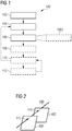
- Fig. 1 illustrates a method 100 according to various embodiments.
- the method 100 is guidable by N elongate guide members 300, and seeks to provide meaningful real-time visualization of the elongate guide members 300 within a surrounding body portion of interest during a clinical intervention.
- the method 100 provisions interventionists with real-time digital images by systematic positioning of two-dimensional planes (image slices) in a three-dimensional image space, such as supplied by various spatial imaging techniques like computer tomography (CT) or magnetic resonance imaging (MRI), and providing the real-time digital images corresponding to these image slices.
- CT computer tomography
- MRI magnetic resonance imaging
- the systematic positioning of the image slices is guided by the elongate guide members 300.
- guidable may relate to a capability of being guided.
- elongate may relate to “long”, “linear” or “having a much greater length than width, diameter or cross-section”.
- a "guide member” may in particular relate to a long and thin member such as a surgical needle which may be used to guide a clinical intervention procedure (in)to a point target or target region.
- the elongate guide members 300 may comprise a surgical needle.
- the number N of elongate guide members 300 may be a positive integer, and may in particular equal 1.
- a most general embodiment of the method 100 comprises method steps 102, 104 and 106.
- Step 102 involves a) establishing N+1 first spatial imaging planes (tracking slices) 400 each having an intersection 410 with each of the N elongate guide members 300.
- a "first spatial imaging plane" may relate to an image slice as previously mentioned which is used for tracking the N elongate guide members 300 during a clinical intervention procedure.
- the first spatial imaging planes 400 may be arranged parallel to one another.
- parallel may relate to a spatial arrangement of two-dimensional planes in a three-dimensional space wherein the planes do not touch each other.
- an "intersection” may relate to point of penetration of a plane (tracking slice 400) by a line (needle 300) .
- performing a) may involve applying known image processing algorithms to non-parallel or parallel tracking slices 400 such as those provided by the above-mentioned spatial imaging techniques, for example.
- Step 104 involves b) determining a spatial orientation of each of the N elongate guide members 300 based on the intersection 410 of the respective guide member with each of the first spatial imaging planes 400.
- Step 106 involves c) identifying at least one second spatial imaging plane (display slice) 500 along or perpendicular to the respective determined spatial orientation of each of the N elongate guide members 300.
- a "second spatial imaging plane" may relate to an image slice as previously mentioned which is used for displaying the N elongate guide members 300 within a context of a surrounding body portion of interest during a clinical intervention procedure.
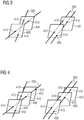
- Fig. 2 illustrates circumstances of the method 100 according to various embodiments concerning the establishing 102 and determining 104 steps.
- the two tracking slices 400 are established to respectively have an intersection 410 with the single needle 300.
- the tracking slices 400 may have arbitrary spatial orientations, and preferably are arranged in parallel to one another.
- the tracking slices 400 may have an arbitrary distance with respect to each other, as long as the respective tracking slice 400 intersects with the needle 300.
- step 104 This advantageously reduces a computational complexity of the method 100 and simplifies subsequent calculations in connection with step 104 (see below), as various spatial imaging techniques readily provide parallel image slices, which may be used as tracking slices 400.
- intersections 410 may be represented by three-dimensional coordinates.
- a spatial orientation of the line is thus given by the vector: x 1 ⁇ x 0 , y 1 ⁇ y 0 , z 1 ⁇ z 0
- the main challenge is to unambiguously identify a respective needle 300 based on its intersections 410 with each of the tracking slices 400.
- FIG. 3 illustrates two different cases involving identical intersections 410 on two tracking slices 400 but yet resolution of individual needles 300 is ambiguous.
- interpretation of the intersections 410 of the two tracking slices 400 may yield two different sets of straight lines, or needles 300, as indicated by the lines drawn through the known intersections 410 with the tracking slices 400. It is thus evident that two tracking slices 400 are not enough to unambiguously determine two individual needles 300.
- Fig. 4 illustrates circumstances of the method 100 according to various embodiments concerning the establishing 102 and determining 104 steps.
- This rule can be extrapolated linearly: For any number N of needles 300 in consideration used at the same time, it is required to create N+1 tracking slices 400 each having N intersections 410 to unambiguously identify all the needles 300.
- the following is undertaken in order to automatically follow a needle 300 during measurement.
- Fig. 4 three (i.e., N+1) tracking slices 400 are established to respectively have two (N) intersections 410 with the two (N) needles 300.
- intersections 410 may be represented by three-dimensional coordinates.
- intersections 410 corresponding to a same needle 300 align with one another along a spatial orientation of the respective needle 300.
- the method 100 may further comprise steps 108, 110 and/or 112.
- the method 100 may further comprise displaying the at least one second spatial imaging plane 500 of at least one of the N elongate guide members 300.
- the method 100 provisions interventionists with real-time digital images by providing the real-time digital images corresponding to systematically positioned two-dimensional planes (i.e., the at least one second spatial imaging plane, or display slice 500) in a three-dimensional image space, such as supplied by various spatial imaging techniques like computer tomography (CT) or magnetic resonance imaging (MRI).
- CT computer tomography
- MRI magnetic resonance imaging
- the above-mentioned spatial imaging techniques readily provide a three-dimensional image space formed of parallel image slices from which the at least one display slice 500 may be derived.
- a display slice 500 may be formed by using or copying the image content of the three-dimensional image space that coincides spatially with the two-dimensional plane of the at least one display slice 500 as or into the at least one display slice 500.
- This advantageously enables continuous monitoring of the particular needle(s) 300 along its/their path(s) (i.e., on a respective display slice 500) and within a surrounding body portion of interest during the whole clinical intervention procedure.
- this improves a usability of a user interface of a device which is configured to perform the method 100, as it is much easier for an interventionist to understand a digital image content of a properly positioned and oriented display slice 500 rather than a digital image content dispersed over a set of parallel image slices which respectively intersect with this display slice 500.
- the method 100 advantageously enables simultaneous and continuous monitoring of two or more needles 300 along their respective path and within a surrounding body portion of interest during the whole clinical intervention procedure.
- continuous monitoring is achieved through automatic realignment of a spatial position/orientation of the respective display slice 500 during the intervention procedure in order to keep all the needles 300 involved visible on a respective display slice 500 all the time.
- the continuous needle visibility is of crucial importance during clinical use cases like tissue removal, etc.
- this reduces a time necessary for insertion of needles 300 as these remain visible all the time and do not require frequent manual re-adjustment, which conventionally may have required re-adjustment of corresponding tracking slices 400.
- needles 300 may be moved constantly during a clinical intervention, it is possible that some intersections 410 between the respective needle 300 and the tracking slices 400 disappear from the respective tracking slice 400.
- the method 100 may further comprise, in response to a trigger event, d) detecting if each of the first spatial imaging planes 400 still has an intersection 410 with each of the N elongate guide members 300.
- a same or similar known method may be used as for performing a), and that the detecting 110 may be based on the tracking slices 400 having known spatial positions/orientations.
- the trigger event may comprise a lapse of a timer and/or an indication that at least one of the intersections 410 has moved within its corresponding tracking slice 400 in excess of a given threshold.
- the detecting 110 under timer control will ensure a simple but close monitoring of needle's movement, whereas the demand-driven detecting 110 in response to an indication of movement may reduce a workload of an underlying processing device 202 (see below in connection with Fig. 7 ) arranged to perform the detecting 110.
- an indication of movement may arise if at least one intersection 410 between a needle 300 and a tracking slice 400 has moved away within that tracking slice 400 from a last known position in excess of a given distance threshold.
- an indication of movement may arise if at least one intersection 410 may not be retrieved anymore within a given distance threshold from the last known position.
- the method 100 may further comprise proceeding at step 0 in response to detecting 110 that each of the first spatial imaging planes 400 has an intersection 410 with each of the N elongate guide members 300.
- the method proceeds at step 104 to determine a spatial orientation of each of the N needles 300 based on the intersection 410 of the respective needle 300 with each of the tracking slices 400.
- Fig. 5 illustrates circumstances of the method 100 according to various embodiments concerning the displacing step 112.
- the method 100 may thus further comprise displacing 112, in accordance with at least one of the determined spatial orientations, the at least one of the first spatial imaging planes 400 not having an intersection 410 with each of the N elongate guide members 300 to be located closer to one of the first spatial imaging planes 400 having an intersection 410 with each of the N elongate guide members 300, and proceeding at step 0.
- This may be performed in response to detecting 110 that at least one of the first spatial imaging planes 400 does not have an intersection 410 with each of the N elongate guide members 300.
- displacement may relate to moving out of position, preferably by means of translation.
- the method proceeds at step d) for detecting 110 if each of the tracking slices 400 (including the displaced tracking slice(s) 400) has an intersection 410 with each of the N needles 300.
- the displacing 112 of a tracking slice 400 may be carried out repeatedly to ensure that the displaced tracking slice 400 captures all N intersections 410.
- the one of the first spatial imaging planes 400 having an intersection 410 with each of the N elongate guide members 300 may have a largest spacing, in accordance with the at least one of the determined spatial orientations, relative to the at least one of the first spatial imaging planes 400 not having an intersection 410 with each of the N elongate guide members 300.
- the tracking slice 400 to be displaced would automatically be displaced towards the tracking slice 400 that is closest to the entry point(s) of the needle(s) 300 in the skin surface of the patient who undergoes the intervention procedure.
- Fig. 6 illustrates circumstances of the method 100 according to various embodiments concerning the identifying step 106.
- the identifying 106 at least one second spatial imaging plane 500 may comprise identifying 1062 three mutually orthogonal second spatial imaging planes 500 along or perpendicular to the respective determined spatial orientation of each of the N elongate guide members 300.
- intersections 410 may be represented by three-dimensional coordinates.
- a spatial orientation of the line is thus given by the vector: x 1 ⁇ x 0 , y 1 ⁇ y 0 , z 1 ⁇ z 0
- a display slice 500 perpendicular to the two given, mutually perpendicular planes may be determined based on an arbitrary point ( x 0 , y 0 , z 0 ) on the given line and a vector ( a, b, c ) that lies on the line.
- up to three display slices 500 may be displayed to the user per needle 300 with the entire needle 300 shown on two of these display slices 500 which are not orthogonal to the respective needle 300, while a third display slice 500 merely shows an intersection with the needle 300.
- Fig. 7 illustrates an imaging device 200 according to various embodiments.
- the imaging device 200 is for performing a method 100 which is guidable by N elongate guide members 300 and seeks to provide meaningful real-time visualization of the elongate guide members 300 within a surrounding body portion of interest during a clinical intervention.
- a most general embodiment of the imaging device 200 comprises at least one processing device 202 being arranged for performing the method steps 102, 104 and 106.
- Step 102 involves a) establishing N+1 first spatial imaging planes 400 each having an intersection 410 with each of the N elongate guide members 300.
- the first spatial imaging planes 400 may be arranged parallel to one another.
- Step 104 involves b) determining a spatial orientation of each of the N elongate guide members 300 based on the intersection 410 of the respective guide member with each of the first spatial imaging planes 400.
- Step 106 involves c) identifying at least one second spatial imaging plane 500 along or perpendicular to the respective determined spatial orientation of each of the N elongate guide members 300.
- the at least one processing device 202 may further be arranged for performing the method 100 according to various embodiments.
- imaging device 200 and the above-defined method 100 have corresponding features.
Landscapes
- Health & Medical Sciences (AREA)
- Life Sciences & Earth Sciences (AREA)
- Engineering & Computer Science (AREA)
- Surgery (AREA)
- Medical Informatics (AREA)
- Nuclear Medicine, Radiotherapy & Molecular Imaging (AREA)
- Heart & Thoracic Surgery (AREA)
- Animal Behavior & Ethology (AREA)
- Veterinary Medicine (AREA)
- Pathology (AREA)
- Public Health (AREA)
- Biomedical Technology (AREA)
- General Health & Medical Sciences (AREA)
- Molecular Biology (AREA)
- Radiology & Medical Imaging (AREA)
- Biophysics (AREA)
- Physics & Mathematics (AREA)
- High Energy & Nuclear Physics (AREA)
- Optics & Photonics (AREA)
- Gynecology & Obstetrics (AREA)
- Oral & Maxillofacial Surgery (AREA)
- Human Computer Interaction (AREA)
- Computer Graphics (AREA)
- General Engineering & Computer Science (AREA)
- Magnetic Resonance Imaging Apparatus (AREA)
Abstract
Description
- Various embodiments of the invention relate to an imaging device and a method of operating the same. Various embodiments relate in particular to imaging in support of clinical intervention procedures.
- Tissue removal, fluid removal or ablation are ones of typical clinical interventions where a needle is inserted into a patient's body in order to access an internal body portion of interest. Tissue removal (biopsy) from a body is usually performed in order to examine the presence, cause or extent of a disease in body portions such as for example in breast, liver, kidney, skin biopsy, etc. Fluid removal (paracentesis) from a body is usually performed in order to remove accumulated unwanted fluid from body portions such as abdomen or lungs. Ablation is usually performed in the course of cancer treatment, wherein a tumor is exposed to energy of electromagnetic or radio waves or ethanol injections to damage cancer cells.
- In all of the above clinical interventions, the needle's trajectory/path between an entry point (skin surface) and a targeted body part is usually determined before the intervention takes place. Once the path is defined, the needle must follow this given path.
- In known interventional procedures, the needle is inserted and controlled manually by an interventionist. As such, the needle is prone to certain deviation from the given path and needs to be monitored constantly by the interventionist using visual monitoring of an image slice aligned with the predefined path. Continuous monitoring of the needle's movement and path is thus a crucial part of the intervention.
- For example, an intersection between the needle and the image slice may be shown to the interventionist. As soon as the needle deviates from the given path or even disappears from the image slice due to human error, it needs to be adjusted manually and returned to the predefined path in order to avoid unintentional damage to the neighboring tissue or body parts on the needle's path. This process ensures that the needle stays on the predefined path all the time, but is error-prone, slow and it leads to unpleasant procedure for a patient and tiring and long procedure for everybody.
- However, if an arbitrary path is allowed when the path is not defined in advance and the needle would target a region (e.g. an accumulation of liquid, etc.) rather than a point target, this method becomes insufficient. In such case, constant monitoring usually requires another person (such as a scanner software operator) to continuously adjust the image slice's spatial position in order to follow the needle's path during the intervention. This is done manually without a guarantee that the needle will be constantly followed and for that reason intensive coordination between interventionist and operator is required in order to ensure satisfactory needle visibility on the slice.
- This technique is even more error-prone when guidance by multiple needles required, since some interventions involve more than one needle in the clinical intervention procedure at the same time. When multiple needles need to be monitored in parallel, this process is particularly slow.
- In view of the above, there is a continued need in the art for methods and devices which address some of the above needs.
- This need is met by the features of the independent claims. The dependent claims define preferred and advantageous embodiments.
- According to a first aspect, a method for operating an imaging device is provided. The method is guidable by N elongate guide members and comprises:
- a) establishing N+1 first spatial imaging planes each having an intersection with each of the N elongate guide members;
- b) determining a spatial orientation of each of the N elongate guide members based on the intersection of the respective guide member with each of the first spatial imaging planes; and
- c) identifying at least one second spatial imaging plane along or perpendicular to the respective determined spatial orientation of each of the N elongate guide members.
- The method may further comprise: in response to a trigger event, d) detecting if each of the first spatial imaging planes still has an intersection with each of the N elongate guide members.
- The trigger event may comprise at least one of a lapse of a timer and/or an indication that at least one of the
intersections 410 has moved within the corresponding first spatial imaging plane in excess of a given threshold. - The method may further comprise: in response to detecting that each of the first spatial imaging planes has an intersection with each of the N elongate guide members, proceeding at step b).
- The method may further comprise: in response to detecting that at least one of the first spatial imaging planes does not have an intersection with each of the N elongate guide members, displacing the at least one of the first spatial imaging planes not having an intersection with each of the N elongate guide members to be located closer to, in accordance with at least one of the determined spatial orientations, one of the first spatial imaging planes having an intersection with each of the N elongate guide members, and proceeding at step d).
- The one of the first spatial imaging planes having an intersection with each of the N elongate guide members may have a largest spacing, in accordance with the at least one of the determined spatial orientations, relative to the at least one of the first spatial imaging planes not having an intersection with each of the N elongate guide members.
- The method may further comprise: displaying the at least one second spatial imaging plane of at least one of the N elongate guide members.
- Identifying at least one second spatial imaging plane may comprise identifying three mutually orthogonal second spatial imaging planes along or perpendicular to the respective determined spatial orientation of each of the N elongate guide members.
- The number N of elongate guide members may be a positive integer.
- The number N of elongate guide members may equal 1.
- The elongate guide members may comprise a surgical needle.
- The first spatial imaging planes may be arranged parallel to one another.
- According to a second aspect, an imaging device is provided. The imaging device is for performing a method being guidable by N elongate guide members and comprises at least one processing device being arranged for
- a) establishing N+1 first spatial imaging planes each having an intersection with each of the N elongate guide members;
- b) determining a spatial orientation of each of the N elongate guide members based on the intersection of the respective guide member with each of the first spatial imaging planes; and
- c) identifying at least one second spatial imaging plane along or perpendicular to the respective determined spatial orientation of each of the N elongate guide members.
- The at least one processing device may further be arranged for performing the method of various embodiments.
- Embodiments of the invention will be described with reference to the accompanying drawings, in which the same or similar reference numerals designate the same or similar elements.
- Fig. 1
- illustrates a method according to various embodiments.
- Fig. 2
- illustrates circumstances of the method according to various embodiments concerning the establishing and determining steps and involving N=1 elongate guide members and N+1=2 first spatial imaging planes.
- Fig. 3
- illustrates circumstances of a method according to prior art involving N=2 elongate guide members and N=2 first spatial imaging planes.
- Fig. 4
- illustrates circumstances of the method according to various embodiments concerning the establishing and determining steps and involving N=2 elongate guide members and N+1=3 first spatial imaging planes.
- Fig. 5
- illustrates circumstances of the method according to various embodiments concerning the displacing
step 112. - Fig. 6
- illustrates circumstances of the method according to various embodiments concerning the identifying
step 106. - Fig. 7
- illustrates an imaging device according to various embodiments.
- Exemplary embodiments of the invention will now be described with reference to the drawings. While some embodiments will be described in the context of specific fields of application, the embodiments are not limited to this field of application. Further, the features of the various embodiments may be combined with each other unless specifically stated otherwise.
- The drawings are to be regarded as being schematic representations and elements illustrated in the drawings are not necessarily shown to scale. Rather, the various elements are represented such that their function and general purpose become apparent to a person skilled in the art.
-
Fig. 1 illustrates amethod 100 according to various embodiments. - The
method 100 is guidable by Nelongate guide members 300, and seeks to provide meaningful real-time visualization of theelongate guide members 300 within a surrounding body portion of interest during a clinical intervention. - The
method 100 provisions interventionists with real-time digital images by systematic positioning of two-dimensional planes (image slices) in a three-dimensional image space, such as supplied by various spatial imaging techniques like computer tomography (CT) or magnetic resonance imaging (MRI), and providing the real-time digital images corresponding to these image slices. The systematic positioning of the image slices is guided by theelongate guide members 300. - As used herein, "guidable" may relate to a capability of being guided.
- As used herein, "elongate" may relate to "long", "linear" or "having a much greater length than width, diameter or cross-section".
- As used herein, a "guide member" may in particular relate to a long and thin member such as a surgical needle which may be used to guide a clinical intervention procedure (in)to a point target or target region.
- In particular, the
elongate guide members 300 may comprise a surgical needle. - In particular, the number N of
elongate guide members 300 may be a positive integer, and may in particular equal 1. - As indicated by solid lines in
Fig. 1 , a most general embodiment of themethod 100 comprises method steps 102, 104 and 106. - Step 102 involves a) establishing N+1 first spatial imaging planes (tracking slices) 400 each having an
intersection 410 with each of the Nelongate guide members 300. - As used herein, a "first spatial imaging plane" may relate to an image slice as previously mentioned which is used for tracking the N
elongate guide members 300 during a clinical intervention procedure. - In particular, the first spatial imaging planes 400 may be arranged parallel to one another.
- As used herein, "parallel" may relate to a spatial arrangement of two-dimensional planes in a three-dimensional space wherein the planes do not touch each other.
- As used herein, an "intersection" may relate to point of penetration of a plane (tracking slice 400) by a line (needle 300) .
- Those skilled in the art will appreciate that performing a) may involve applying known image processing algorithms to non-parallel or parallel tracking slices 400 such as those provided by the above-mentioned spatial imaging techniques, for example.
- Step 104 involves b) determining a spatial orientation of each of the N
elongate guide members 300 based on theintersection 410 of the respective guide member with each of the first spatial imaging planes 400. - Step 106 involves c) identifying at least one second spatial imaging plane (display slice) 500 along or perpendicular to the respective determined spatial orientation of each of the N
elongate guide members 300. - As used herein, a "second spatial imaging plane" may relate to an image slice as previously mentioned which is used for displaying the N
elongate guide members 300 within a context of a surrounding body portion of interest during a clinical intervention procedure. - This ensures a continuous optimal positioning of the at least one
display slice 500 associated with therespective needle 300 in both single and multiple needle scenarios, which are explained next. -
Fig. 2 illustrates circumstances of themethod 100 according to various embodiments concerning the establishing 102 and determining 104 steps. The case illustrated inFig. 2 involves N=1 elongate guide members (needles) 300 and N+1=2 first spatial imaging planes (tracking slices) 400. - According to
Fig. 2 , the two trackingslices 400 are established to respectively have anintersection 410 with thesingle needle 300. - In general, the tracking slices 400 may have arbitrary spatial orientations, and preferably are arranged in parallel to one another.
- In particular, the tracking slices 400 may have an arbitrary distance with respect to each other, as long as the
respective tracking slice 400 intersects with theneedle 300. - This advantageously reduces a computational complexity of the
method 100 and simplifies subsequent calculations in connection with step 104 (see below), as various spatial imaging techniques readily provide parallel image slices, which may be used as trackingslices 400. - Those skilled in the art will appreciate that it is possible to determine a spatial orientation of the
needle 300 using simple geometry as indicated by the line drawn through the two knownintersections 410 with the tracking slices 400, whichintersections 410 may be represented by three-dimensional coordinates. - More specifically, in a three-dimensional Cartesian space, a linear function or line (x, y, z) passing through points (x 0, y 0, z 0) and (x 1, y 1, z 1) may be defined as follows:


- A spatial orientation of the line is thus given by the vector:

- Regarding scenarios involving
multiple needles 300, the main challenge is to unambiguously identify arespective needle 300 based on itsintersections 410 with each of the tracking slices 400. -
Fig. 3 illustrates circumstances of a known imaging method according to prior art involving N=2elongate guide members 300 and N=2 first spatial imaging planes 400. - More specifically,
Fig. 3 illustrates two different cases involvingidentical intersections 410 on two trackingslices 400 but yet resolution ofindividual needles 300 is ambiguous. - In particular, interpretation of the
intersections 410 of the two trackingslices 400 may yield two different sets of straight lines, or needles 300, as indicated by the lines drawn through the knownintersections 410 with the tracking slices 400. It is thus evident that two trackingslices 400 are not enough to unambiguously determine twoindividual needles 300. -
Fig. 4 illustrates circumstances of themethod 100 according to various embodiments concerning the establishing 102 and determining 104 steps. The case illustrated inFig. 4 involves N=2 elongate guide members and N+1=3 first spatial imaging planes. - Two different cases are shown involving
different intersections 410 on three trackingslices 400, respectively. It is evident that the three trackingslices 400 per case unambiguously identify a spatial position/orientation of the twoneedles 300. - This rule can be extrapolated linearly:
For any number N ofneedles 300 in consideration used at the same time, it is required to create N+1 tracking slices 400 each havingN intersections 410 to unambiguously identify all theneedles 300. - The following is undertaken in order to automatically follow a
needle 300 during measurement. - According to
Fig. 4 , three (i.e., N+1) trackingslices 400 are established to respectively have two (N)intersections 410 with the two (N) needles 300. - The above remarks regarding parallel spatial orientations and arbitrary distance of tracking
slices 400 apply analogously in the multiple needle scenario. - Those skilled in the art will appreciate that it is possible to determine a respective spatial orientation of the two (N) needles 300 using simple geometry as indicated by the lines drawn through the respective three known
intersections 410 with the tracking slices 400, whichintersections 410 may be represented by three-dimensional coordinates. - In particular, the
intersections 410 corresponding to asame needle 300 align with one another along a spatial orientation of therespective needle 300. - As indicated by dashed lines in
Fig. 1 , themethod 100 may further comprisesteps - In
step 108, themethod 100 may further comprise displaying the at least one secondspatial imaging plane 500 of at least one of the Nelongate guide members 300. - In other words, the
method 100 provisions interventionists with real-time digital images by providing the real-time digital images corresponding to systematically positioned two-dimensional planes (i.e., the at least one second spatial imaging plane, or display slice 500) in a three-dimensional image space, such as supplied by various spatial imaging techniques like computer tomography (CT) or magnetic resonance imaging (MRI). This systematic positioning of the display slices 500 is guided by theelongate guide members 300. - For example, the above-mentioned spatial imaging techniques readily provide a three-dimensional image space formed of parallel image slices from which the at least one
display slice 500 may be derived. In particular, adisplay slice 500 may be formed by using or copying the image content of the three-dimensional image space that coincides spatially with the two-dimensional plane of the at least onedisplay slice 500 as or into the at least onedisplay slice 500. - This advantageously enables continuous monitoring of the particular needle(s) 300 along its/their path(s) (i.e., on a respective display slice 500) and within a surrounding body portion of interest during the whole clinical intervention procedure. In particular, this improves a usability of a user interface of a device which is configured to perform the
method 100, as it is much easier for an interventionist to understand a digital image content of a properly positioned and orienteddisplay slice 500 rather than a digital image content dispersed over a set of parallel image slices which respectively intersect with thisdisplay slice 500. - In addition, the
method 100 advantageously enables simultaneous and continuous monitoring of two ormore needles 300 along their respective path and within a surrounding body portion of interest during the whole clinical intervention procedure. - Accordingly, in both single and multiple needle scenarios, continuous monitoring is achieved through automatic realignment of a spatial position/orientation of the
respective display slice 500 during the intervention procedure in order to keep all theneedles 300 involved visible on arespective display slice 500 all the time. The continuous needle visibility is of crucial importance during clinical use cases like tissue removal, etc. - In addition, this reduces a time necessary for insertion of
needles 300 as these remain visible all the time and do not require frequent manual re-adjustment, which conventionally may have required re-adjustment of corresponding tracking slices 400. - Since
needles 300 may be moved constantly during a clinical intervention, it is possible that someintersections 410 between therespective needle 300 and the tracking slices 400 disappear from therespective tracking slice 400. - Thus, in
step 110, themethod 100 may further comprise, in response to a trigger event, d) detecting if each of the firstspatial imaging planes 400 still has anintersection 410 with each of the Nelongate guide members 300. - Those skilled in the art will appreciate that for performing d) a same or similar known method may be used as for performing a), and that the detecting 110 may be based on the tracking slices 400 having known spatial positions/orientations.
- In particular, the trigger event may comprise a lapse of a timer and/or an indication that at least one of the
intersections 410 has moved within its correspondingtracking slice 400 in excess of a given threshold. - Those skilled in the art will appreciate that the detecting 110 under timer control will ensure a simple but close monitoring of needle's movement, whereas the demand-driven detecting 110 in response to an indication of movement may reduce a workload of an underlying processing device 202 (see below in connection with
Fig. 7 ) arranged to perform the detecting 110. - For example, an indication of movement may arise if at least one
intersection 410 between aneedle 300 and atracking slice 400 has moved away within that trackingslice 400 from a last known position in excess of a given distance threshold. Alternatively or additionally, an indication of movement may arise if at least oneintersection 410 may not be retrieved anymore within a given distance threshold from the last known position. - The
method 100 may further comprise proceeding at step 0 in response to detecting 110 that each of the first spatial imaging planes 400 has anintersection 410 with each of the Nelongate guide members 300. - In other words, if a complete set of
N intersections 410 can be found per trackingslice 400 in the detecting 110 step, the method proceeds atstep 104 to determine a spatial orientation of each of the N needles 300 based on theintersection 410 of therespective needle 300 with each of the tracking slices 400. -
Fig. 5 illustrates circumstances of themethod 100 according to various embodiments concerning the displacingstep 112. - If some of necessary intersections are missing (e.g. a
particular tracking slice 400 has less then N intersections), it is required to find anothertracking slice 400 that captures all N intersections. - The
method 100 may thus further comprise displacing 112, in accordance with at least one of the determined spatial orientations, the at least one of the firstspatial imaging planes 400 not having anintersection 410 with each of the Nelongate guide members 300 to be located closer to one of the firstspatial imaging planes 400 having anintersection 410 with each of the Nelongate guide members 300, and proceeding at step 0. This may be performed in response to detecting 110 that at least one of the first spatial imaging planes 400 does not have anintersection 410 with each of the Nelongate guide members 300. - As used herein, "displacing" may relate to moving out of position, preferably by means of translation.
- This advantageously enables automatic retrieval of
needles 300 once they are "lost", i.e., partially or entirely disappear from trackingslices 400. - After displacement of the at least one of the tracking slices 400, the method proceeds at step d) for detecting 110 if each of the tracking slices 400 (including the displaced tracking slice(s) 400) has an
intersection 410 with each of the N needles 300. - In particular, the displacing 112 of a
tracking slice 400 may be carried out repeatedly to ensure that the displacedtracking slice 400 captures allN intersections 410. - In particular, the one of the first
spatial imaging planes 400 having anintersection 410 with each of the Nelongate guide members 300 may have a largest spacing, in accordance with the at least one of the determined spatial orientations, relative to the at least one of the firstspatial imaging planes 400 not having anintersection 410 with each of the Nelongate guide members 300. - In other words, the tracking
slice 400 to be displaced would automatically be displaced towards the trackingslice 400 that is closest to the entry point(s) of the needle(s) 300 in the skin surface of the patient who undergoes the intervention procedure. -
Fig. 6 illustrates circumstances of themethod 100 according to various embodiments concerning the identifyingstep 106. - The identifying 106 at least one second
spatial imaging plane 500 may comprise identifying 1062 three mutually orthogonal secondspatial imaging planes 500 along or perpendicular to the respective determined spatial orientation of each of the Nelongate guide members 300. - Those skilled in the art will appreciate that it is possible to determine a spatial orientation of each of the N elongate guide members (needles) 300 using simple geometry as indicated in
Fig. 2 by the line drawn through the two knownintersections 410 with the tracking slices 400, whichintersections 410 may be represented by three-dimensional coordinates. - More specifically, in a three-dimensional Cartesian space, a linear function or line (x, y, z) passing through points (x 0, y0, z 0) and (x 1, y 1, z 1) may be defined as follows:


- A spatial orientation of the line is thus given by the vector:

- A
display slice 500 comprising the given line may be determined for any chosen point (x 0, y 0, z 0) on the line and any arbitrary vector (a, b, c) as follows (point direction form) :
- A
display slice 500 perpendicular to the given line may be determined for two arbitrary points (x 0, y 0, z 0) and (x 1, y 1, z 1) on the given line and a third arbitrary point (x 2, y 2, z 2) on the plane comprising the line as follows (three point form):
- A
display slice 500 perpendicular to the two given, mutually perpendicular planes may be determined based on an arbitrary point (x 0, y 0, z 0) on the given line and a vector (a, b, c) that lies on the line. In this case, the plane will be perpendicular to vector (a, b, c), comprise the given point (x 0, y 0, z 0), and be perpendicular to the given perpendicular planes:
- Accordingly, up to three
display slices 500 may be displayed to the user perneedle 300 with theentire needle 300 shown on two of these display slices 500 which are not orthogonal to therespective needle 300, while athird display slice 500 merely shows an intersection with theneedle 300. -
Fig. 7 illustrates animaging device 200 according to various embodiments. - The
imaging device 200 is for performing amethod 100 which is guidable by Nelongate guide members 300 and seeks to provide meaningful real-time visualization of theelongate guide members 300 within a surrounding body portion of interest during a clinical intervention. - A most general embodiment of the
imaging device 200 comprises at least oneprocessing device 202 being arranged for performing the method steps 102, 104 and 106. - Step 102 involves a) establishing N+1 first
spatial imaging planes 400 each having anintersection 410 with each of the Nelongate guide members 300. - In particular, the first spatial imaging planes 400 may be arranged parallel to one another.
- Step 104 involves b) determining a spatial orientation of each of the N
elongate guide members 300 based on theintersection 410 of the respective guide member with each of the first spatial imaging planes 400. - Step 106 involves c) identifying at least one second
spatial imaging plane 500 along or perpendicular to the respective determined spatial orientation of each of the Nelongate guide members 300. - Additionally, the at least one
processing device 202 may further be arranged for performing themethod 100 according to various embodiments. - In other words, those skilled in the art will appreciate that the
imaging device 200 and the above-definedmethod 100 have corresponding features. - This advantageously confers to the
imaging device 200 the same technical effects and advantages described above in relation with themethod 100. - While exemplary embodiments incorporating the principles of the present disclosure have been disclosed hereinabove, the present disclosure is not limited to the disclosed embodiments. Instead, this application is intended to cover any variations, uses, or adaptations of the disclosure using its general principles. Further, this application is intended to cover such departures from the present disclosure as come within known or customary practice in the art to which this disclosure pertains and which fall within the limits of the appended claims.
Claims (14)
- An method (100) of operating an imaging device (200), the method (100) being guidable by N elongate guide members (300) and comprising:- establishing (102) N+1 first spatial imaging planes (400) each having an intersection (410) with each of the N elongate guide members (300),- determining (104) a spatial orientation of each of the N elongate guide members (300) based on the intersection (410) of the respective guide member with each of the first spatial imaging planes (400), and- identifying (106) at least one second spatial imaging plane (500) along or perpendicular to the respective determined spatial orientation of each of the N elongate guide members (300) .
- The method (100) of claim 1, further comprising:
in response to a trigger event,- detecting (110) if each of the first spatial imaging planes (400) still has an intersection (410) with each of the N elongate guide members (300). - The method (100) of claim 2, wherein the trigger event comprises at least one of- a lapse of a timer and- an indication that at least one of the intersections 410 has moved within the corresponding first spatial imaging plane (400) in excess of a given threshold.
- The method (100) of claim 2 or claim 3, further comprising:- in response to detecting (110) that each of the first spatial imaging planes (400) has an intersection (410) with each of the N elongate guide members (300), proceeding at step 0.
- The method (100) of any one of claims 2 - 4, further comprising:- in response to detecting (110) that at least one of the first spatial imaging planes (400) does not have an intersection (410) with each of the N elongate guide members (300), displacing (112) the at least one of the first spatial imaging planes (400) not having an intersection (410) with each of the N elongate guide members (300) to be located closer to, in accordance with at least one of the determined spatial orientations, one of the first spatial imaging planes (400) having an intersection (410) with each of the N elongate guide members (300), and proceeding at step 0.
- The method (100) of claim 5,
wherein the one of the first spatial imaging planes (400) having an intersection (410) with each of the N elongate guide members (300) has a largest spacing, in accordance with the at least one of the determined spatial orientations, relative to the at least one of the first spatial imaging planes (400) not having an intersection (410) with each of the N elongate guide members (300). - The method (100) of any one of the preceding claims, further comprising:- displaying (108) the at least one second spatial imaging plane (500) of at least one of the N elongate guide members (300).
- The method (100) of any one of the preceding claims,
wherein identifying (106) at least one second spatial imaging plane (500) comprises identifying (1062) three mutually orthogonal second spatial imaging planes (500) along or perpendicular to the respective determined spatial orientation of each of the N elongate guide members (300). - The method (100) of any one of the preceding claims,
wherein the number N of elongate guide members (300) is a positive integer. - The method (100) of claim 9,
wherein the number N of elongate guide members (300) equals 1. - The method (100) of any one of the preceding claims,
wherein the elongate guide members (300) comprise a surgical needle. - The method (100) of any one of the preceding claims,
wherein the first spatial imaging planes (400) are arranged parallel to one another. - An imaging device (200) for performing a method (100) being guidable by N elongate guide members (300), the imaging device (200) comprising at least one processing device (202) being arranged for- establishing (102) N+1 first spatial imaging planes (400) each having an intersection (410) with each of the N elongate guide members (300);- determining (104) a spatial orientation of each of the N elongate guide members (300) based on the intersection (410) of the respective guide member with each of the first spatial imaging planes (400); and- identifying (106) at least one second spatial imaging plane (500) along or perpendicular to the respective determined spatial orientation of each of the N elongate guide members (300) .
- The device of claim 13,
the at least one processing device (202) further being arranged for performing the method (100) of any one of claims 2 - 12.
Priority Applications (2)
| Application Number | Priority Date | Filing Date | Title |
|---|---|---|---|
| EP19205641.4A EP3815612B1 (en) | 2019-10-28 | 2019-10-28 | Imaging device and method of operating the same |
| US17/081,964 US12082980B2 (en) | 2019-10-28 | 2020-10-27 | Imaging device and method of operating the same |
Applications Claiming Priority (1)
| Application Number | Priority Date | Filing Date | Title |
|---|---|---|---|
| EP19205641.4A EP3815612B1 (en) | 2019-10-28 | 2019-10-28 | Imaging device and method of operating the same |
Publications (2)
| Publication Number | Publication Date |
|---|---|
| EP3815612A1 true EP3815612A1 (en) | 2021-05-05 |
| EP3815612B1 EP3815612B1 (en) | 2023-05-03 |
Family
ID=68382309
Family Applications (1)
| Application Number | Title | Priority Date | Filing Date |
|---|---|---|---|
| EP19205641.4A Active EP3815612B1 (en) | 2019-10-28 | 2019-10-28 | Imaging device and method of operating the same |
Country Status (2)
| Country | Link |
|---|---|
| US (1) | US12082980B2 (en) |
| EP (1) | EP3815612B1 (en) |
Family Cites Families (1)
| Publication number | Priority date | Publication date | Assignee | Title |
|---|---|---|---|---|
| US10188467B2 (en) * | 2014-12-12 | 2019-01-29 | Inneroptic Technology, Inc. | Surgical guidance intersection display |
-
2019
- 2019-10-28 EP EP19205641.4A patent/EP3815612B1/en active Active
-
2020
- 2020-10-27 US US17/081,964 patent/US12082980B2/en active Active
Non-Patent Citations (1)
| Title |
|---|
| GIBBONS E P ET AL: "Overcoming pubic arch interference with free-hand needle placement in men undergoing prostate brachytherapy", BRACHYTHERAPY, ELSEVIER, AMSTERDAM, NL, vol. 8, no. 1, 1 January 2009 (2009-01-01), pages 74 - 78, XP025874203, ISSN: 1538-4721, [retrieved on 20080914], DOI: 10.1016/J.BRACHY.2008.04.007 * |
Also Published As
| Publication number | Publication date |
|---|---|
| US20210121262A1 (en) | 2021-04-29 |
| EP3815612B1 (en) | 2023-05-03 |
| US12082980B2 (en) | 2024-09-10 |
Similar Documents
| Publication | Publication Date | Title |
|---|---|---|
| US10123841B2 (en) | Method for generating insertion trajectory of surgical needle | |
| US6782288B2 (en) | Method and apparatus for positioning a device in a body | |
| EP3964161B1 (en) | Computed tomography enhanced fluoroscopic system, device, and method of utilizing the same | |
| EP1103229B1 (en) | System and method for use with imaging devices to facilitate planning of interventional procedures | |
| JP3749400B2 (en) | Tomography equipment | |
| US20030149351A1 (en) | Curved surgical instruments and method of mapping a curved path for stereotactic surgery | |
| US20140303662A1 (en) | Puncture support device | |
| WO2019100212A1 (en) | Ultrasonic system and method for planning ablation | |
| CN106456135A (en) | Medical treatment system | |
| CN101002205B (en) | Data set visualization | |
| EP3566652A1 (en) | System and method for constructing virtual radial ultrasound images from ct data and performing a surgical navigation procedure using virtual ultrasound images | |
| CN116012452A (en) | A puncture navigation system and method for locating targets based on ultrasound images | |
| CN116269767A (en) | A biopsy system and navigation method based on electromagnetic positioning | |
| JP7258459B2 (en) | Alignment of ENT images | |
| EP2716252B1 (en) | System and method for guiding the manual insertion of a needle into the body of a patient. | |
| EP1787594A2 (en) | System and method for improved ablation of tumors | |
| KR20230013042A (en) | Method for predicting recurrence of lesions through image analysis | |
| CN117618109A (en) | MRI-based breast surgery preoperative focus positioning and puncture guiding system | |
| CN108135577B (en) | Medical system | |
| US12082980B2 (en) | Imaging device and method of operating the same | |
| JPH03231643A (en) | Image display device | |
| Ward et al. | Registration of in vivo prostate magnetic resonance images to digital histopathology images | |
| US11269028B2 (en) | System and method for real-time interventional device localization using magnetic resonance imaging | |
| CN115087384B (en) | Surgical system and surgical method | |
| US20230134815A1 (en) | Guidance system for interventional devices with curved shape |
Legal Events
| Date | Code | Title | Description |
|---|---|---|---|
| PUAI | Public reference made under article 153(3) epc to a published international application that has entered the european phase |
Free format text: ORIGINAL CODE: 0009012 |
|
| STAA | Information on the status of an ep patent application or granted ep patent |
Free format text: STATUS: THE APPLICATION HAS BEEN PUBLISHED |
|
| AK | Designated contracting states |
Kind code of ref document: A1 Designated state(s): AL AT BE BG CH CY CZ DE DK EE ES FI FR GB GR HR HU IE IS IT LI LT LU LV MC MK MT NL NO PL PT RO RS SE SI SK SM TR |
|
| STAA | Information on the status of an ep patent application or granted ep patent |
Free format text: STATUS: REQUEST FOR EXAMINATION WAS MADE |
|
| 17P | Request for examination filed |
Effective date: 20211102 |
|
| RBV | Designated contracting states (corrected) |
Designated state(s): AL AT BE BG CH CY CZ DE DK EE ES FI FR GB GR HR HU IE IS IT LI LT LU LV MC MK MT NL NO PL PT RO RS SE SI SK SM TR |
|
| REG | Reference to a national code |
Ref country code: DE Ref legal event code: R079 Ref document number: 602019028305 Country of ref document: DE Free format text: PREVIOUS MAIN CLASS: A61B0006020000 Ipc: A61B0006000000 |
|
| RIC1 | Information provided on ipc code assigned before grant |
Ipc: A61B 5/055 20060101ALI20221027BHEP Ipc: A61B 5/06 20060101ALI20221027BHEP Ipc: A61B 6/02 20060101ALI20221027BHEP Ipc: A61B 90/00 20160101ALI20221027BHEP Ipc: A61B 8/00 20060101ALI20221027BHEP Ipc: A61B 6/12 20060101ALI20221027BHEP Ipc: A61B 8/08 20060101ALI20221027BHEP Ipc: A61B 6/00 20060101AFI20221027BHEP |
|
| GRAP | Despatch of communication of intention to grant a patent |
Free format text: ORIGINAL CODE: EPIDOSNIGR1 |
|
| STAA | Information on the status of an ep patent application or granted ep patent |
Free format text: STATUS: GRANT OF PATENT IS INTENDED |
|
| INTG | Intention to grant announced |
Effective date: 20221209 |
|
| GRAS | Grant fee paid |
Free format text: ORIGINAL CODE: EPIDOSNIGR3 |
|
| GRAA | (expected) grant |
Free format text: ORIGINAL CODE: 0009210 |
|
| STAA | Information on the status of an ep patent application or granted ep patent |
Free format text: STATUS: THE PATENT HAS BEEN GRANTED |
|
| AK | Designated contracting states |
Kind code of ref document: B1 Designated state(s): AL AT BE BG CH CY CZ DE DK EE ES FI FR GB GR HR HU IE IS IT LI LT LU LV MC MK MT NL NO PL PT RO RS SE SI SK SM TR |
|
| REG | Reference to a national code |
Ref country code: GB Ref legal event code: FG4D |
|
| REG | Reference to a national code |
Ref country code: DE Ref legal event code: R096 Ref document number: 602019028305 Country of ref document: DE |
|
| REG | Reference to a national code |
Ref country code: AT Ref legal event code: REF Ref document number: 1563923 Country of ref document: AT Kind code of ref document: T Effective date: 20230515 Ref country code: CH Ref legal event code: EP |
|
| REG | Reference to a national code |
Ref country code: IE Ref legal event code: FG4D |
|
| REG | Reference to a national code |
Ref country code: LT Ref legal event code: MG9D |
|
| REG | Reference to a national code |
Ref country code: NL Ref legal event code: MP Effective date: 20230503 |
|
| REG | Reference to a national code |
Ref country code: AT Ref legal event code: MK05 Ref document number: 1563923 Country of ref document: AT Kind code of ref document: T Effective date: 20230503 |
|
| PG25 | Lapsed in a contracting state [announced via postgrant information from national office to epo] |
Ref country code: SE Free format text: LAPSE BECAUSE OF FAILURE TO SUBMIT A TRANSLATION OF THE DESCRIPTION OR TO PAY THE FEE WITHIN THE PRESCRIBED TIME-LIMIT Effective date: 20230503 Ref country code: PT Free format text: LAPSE BECAUSE OF FAILURE TO SUBMIT A TRANSLATION OF THE DESCRIPTION OR TO PAY THE FEE WITHIN THE PRESCRIBED TIME-LIMIT Effective date: 20230904 Ref country code: NO Free format text: LAPSE BECAUSE OF FAILURE TO SUBMIT A TRANSLATION OF THE DESCRIPTION OR TO PAY THE FEE WITHIN THE PRESCRIBED TIME-LIMIT Effective date: 20230803 Ref country code: NL Free format text: LAPSE BECAUSE OF FAILURE TO SUBMIT A TRANSLATION OF THE DESCRIPTION OR TO PAY THE FEE WITHIN THE PRESCRIBED TIME-LIMIT Effective date: 20230503 Ref country code: ES Free format text: LAPSE BECAUSE OF FAILURE TO SUBMIT A TRANSLATION OF THE DESCRIPTION OR TO PAY THE FEE WITHIN THE PRESCRIBED TIME-LIMIT Effective date: 20230503 Ref country code: AT Free format text: LAPSE BECAUSE OF FAILURE TO SUBMIT A TRANSLATION OF THE DESCRIPTION OR TO PAY THE FEE WITHIN THE PRESCRIBED TIME-LIMIT Effective date: 20230503 |
|
| PG25 | Lapsed in a contracting state [announced via postgrant information from national office to epo] |
Ref country code: RS Free format text: LAPSE BECAUSE OF FAILURE TO SUBMIT A TRANSLATION OF THE DESCRIPTION OR TO PAY THE FEE WITHIN THE PRESCRIBED TIME-LIMIT Effective date: 20230503 Ref country code: PL Free format text: LAPSE BECAUSE OF FAILURE TO SUBMIT A TRANSLATION OF THE DESCRIPTION OR TO PAY THE FEE WITHIN THE PRESCRIBED TIME-LIMIT Effective date: 20230503 Ref country code: LV Free format text: LAPSE BECAUSE OF FAILURE TO SUBMIT A TRANSLATION OF THE DESCRIPTION OR TO PAY THE FEE WITHIN THE PRESCRIBED TIME-LIMIT Effective date: 20230503 Ref country code: LT Free format text: LAPSE BECAUSE OF FAILURE TO SUBMIT A TRANSLATION OF THE DESCRIPTION OR TO PAY THE FEE WITHIN THE PRESCRIBED TIME-LIMIT Effective date: 20230503 Ref country code: IS Free format text: LAPSE BECAUSE OF FAILURE TO SUBMIT A TRANSLATION OF THE DESCRIPTION OR TO PAY THE FEE WITHIN THE PRESCRIBED TIME-LIMIT Effective date: 20230903 Ref country code: HR Free format text: LAPSE BECAUSE OF FAILURE TO SUBMIT A TRANSLATION OF THE DESCRIPTION OR TO PAY THE FEE WITHIN THE PRESCRIBED TIME-LIMIT Effective date: 20230503 Ref country code: GR Free format text: LAPSE BECAUSE OF FAILURE TO SUBMIT A TRANSLATION OF THE DESCRIPTION OR TO PAY THE FEE WITHIN THE PRESCRIBED TIME-LIMIT Effective date: 20230804 |
|
| PG25 | Lapsed in a contracting state [announced via postgrant information from national office to epo] |
Ref country code: FI Free format text: LAPSE BECAUSE OF FAILURE TO SUBMIT A TRANSLATION OF THE DESCRIPTION OR TO PAY THE FEE WITHIN THE PRESCRIBED TIME-LIMIT Effective date: 20230503 |
|
| PG25 | Lapsed in a contracting state [announced via postgrant information from national office to epo] |
Ref country code: SK Free format text: LAPSE BECAUSE OF FAILURE TO SUBMIT A TRANSLATION OF THE DESCRIPTION OR TO PAY THE FEE WITHIN THE PRESCRIBED TIME-LIMIT Effective date: 20230503 |
|
| PG25 | Lapsed in a contracting state [announced via postgrant information from national office to epo] |
Ref country code: SM Free format text: LAPSE BECAUSE OF FAILURE TO SUBMIT A TRANSLATION OF THE DESCRIPTION OR TO PAY THE FEE WITHIN THE PRESCRIBED TIME-LIMIT Effective date: 20230503 Ref country code: SK Free format text: LAPSE BECAUSE OF FAILURE TO SUBMIT A TRANSLATION OF THE DESCRIPTION OR TO PAY THE FEE WITHIN THE PRESCRIBED TIME-LIMIT Effective date: 20230503 Ref country code: RO Free format text: LAPSE BECAUSE OF FAILURE TO SUBMIT A TRANSLATION OF THE DESCRIPTION OR TO PAY THE FEE WITHIN THE PRESCRIBED TIME-LIMIT Effective date: 20230503 Ref country code: EE Free format text: LAPSE BECAUSE OF FAILURE TO SUBMIT A TRANSLATION OF THE DESCRIPTION OR TO PAY THE FEE WITHIN THE PRESCRIBED TIME-LIMIT Effective date: 20230503 Ref country code: DK Free format text: LAPSE BECAUSE OF FAILURE TO SUBMIT A TRANSLATION OF THE DESCRIPTION OR TO PAY THE FEE WITHIN THE PRESCRIBED TIME-LIMIT Effective date: 20230503 Ref country code: CZ Free format text: LAPSE BECAUSE OF FAILURE TO SUBMIT A TRANSLATION OF THE DESCRIPTION OR TO PAY THE FEE WITHIN THE PRESCRIBED TIME-LIMIT Effective date: 20230503 |
|
| REG | Reference to a national code |
Ref country code: DE Ref legal event code: R097 Ref document number: 602019028305 Country of ref document: DE |
|
| RAP2 | Party data changed (patent owner data changed or rights of a patent transferred) |
Owner name: SIEMENS HEALTHINEERS AG |
|
| REG | Reference to a national code |
Ref country code: DE Ref legal event code: R081 Ref document number: 602019028305 Country of ref document: DE Owner name: SIEMENS HEALTHINEERS AG, DE Free format text: FORMER OWNER: SIEMENS HEALTHCARE GMBH, MUENCHEN, DE |
|
| PLBE | No opposition filed within time limit |
Free format text: ORIGINAL CODE: 0009261 |
|
| STAA | Information on the status of an ep patent application or granted ep patent |
Free format text: STATUS: NO OPPOSITION FILED WITHIN TIME LIMIT |
|
| 26N | No opposition filed |
Effective date: 20240206 |
|
| PG25 | Lapsed in a contracting state [announced via postgrant information from national office to epo] |
Ref country code: SI Free format text: LAPSE BECAUSE OF FAILURE TO SUBMIT A TRANSLATION OF THE DESCRIPTION OR TO PAY THE FEE WITHIN THE PRESCRIBED TIME-LIMIT Effective date: 20230503 |
|
| PG25 | Lapsed in a contracting state [announced via postgrant information from national office to epo] |
Ref country code: SI Free format text: LAPSE BECAUSE OF FAILURE TO SUBMIT A TRANSLATION OF THE DESCRIPTION OR TO PAY THE FEE WITHIN THE PRESCRIBED TIME-LIMIT Effective date: 20230503 Ref country code: IT Free format text: LAPSE BECAUSE OF FAILURE TO SUBMIT A TRANSLATION OF THE DESCRIPTION OR TO PAY THE FEE WITHIN THE PRESCRIBED TIME-LIMIT Effective date: 20230503 Ref country code: MC Free format text: LAPSE BECAUSE OF FAILURE TO SUBMIT A TRANSLATION OF THE DESCRIPTION OR TO PAY THE FEE WITHIN THE PRESCRIBED TIME-LIMIT Effective date: 20230503 |
|
| REG | Reference to a national code |
Ref country code: CH Ref legal event code: PL |
|
| REG | Reference to a national code |
Ref country code: BE Ref legal event code: MM Effective date: 20231031 |
|
| PG25 | Lapsed in a contracting state [announced via postgrant information from national office to epo] |
Ref country code: LU Free format text: LAPSE BECAUSE OF NON-PAYMENT OF DUE FEES Effective date: 20231028 |
|
| PG25 | Lapsed in a contracting state [announced via postgrant information from national office to epo] |
Ref country code: LU Free format text: LAPSE BECAUSE OF NON-PAYMENT OF DUE FEES Effective date: 20231028 |
|
| PG25 | Lapsed in a contracting state [announced via postgrant information from national office to epo] |
Ref country code: CH Free format text: LAPSE BECAUSE OF NON-PAYMENT OF DUE FEES Effective date: 20231031 |
|
| PG25 | Lapsed in a contracting state [announced via postgrant information from national office to epo] |
Ref country code: CH Free format text: LAPSE BECAUSE OF NON-PAYMENT OF DUE FEES Effective date: 20231031 |
|
| PG25 | Lapsed in a contracting state [announced via postgrant information from national office to epo] |
Ref country code: BE Free format text: LAPSE BECAUSE OF NON-PAYMENT OF DUE FEES Effective date: 20231031 |
|
| PG25 | Lapsed in a contracting state [announced via postgrant information from national office to epo] |
Ref country code: IE Free format text: LAPSE BECAUSE OF NON-PAYMENT OF DUE FEES Effective date: 20231028 |
|
| PG25 | Lapsed in a contracting state [announced via postgrant information from national office to epo] |
Ref country code: IE Free format text: LAPSE BECAUSE OF NON-PAYMENT OF DUE FEES Effective date: 20231028 |
|
| PG25 | Lapsed in a contracting state [announced via postgrant information from national office to epo] |
Ref country code: BG Free format text: LAPSE BECAUSE OF FAILURE TO SUBMIT A TRANSLATION OF THE DESCRIPTION OR TO PAY THE FEE WITHIN THE PRESCRIBED TIME-LIMIT Effective date: 20230503 |
|
| PG25 | Lapsed in a contracting state [announced via postgrant information from national office to epo] |
Ref country code: BG Free format text: LAPSE BECAUSE OF FAILURE TO SUBMIT A TRANSLATION OF THE DESCRIPTION OR TO PAY THE FEE WITHIN THE PRESCRIBED TIME-LIMIT Effective date: 20230503 |
|
| PG25 | Lapsed in a contracting state [announced via postgrant information from national office to epo] |
Ref country code: CY Free format text: LAPSE BECAUSE OF FAILURE TO SUBMIT A TRANSLATION OF THE DESCRIPTION OR TO PAY THE FEE WITHIN THE PRESCRIBED TIME-LIMIT; INVALID AB INITIO Effective date: 20191028 |
|
| PG25 | Lapsed in a contracting state [announced via postgrant information from national office to epo] |
Ref country code: HU Free format text: LAPSE BECAUSE OF FAILURE TO SUBMIT A TRANSLATION OF THE DESCRIPTION OR TO PAY THE FEE WITHIN THE PRESCRIBED TIME-LIMIT; INVALID AB INITIO Effective date: 20191028 |
|
| PG25 | Lapsed in a contracting state [announced via postgrant information from national office to epo] |
Ref country code: TR Free format text: LAPSE BECAUSE OF FAILURE TO SUBMIT A TRANSLATION OF THE DESCRIPTION OR TO PAY THE FEE WITHIN THE PRESCRIBED TIME-LIMIT Effective date: 20230503 |
|
| PGFP | Annual fee paid to national office [announced via postgrant information from national office to epo] |
Ref country code: GB Payment date: 20251111 Year of fee payment: 7 |
|
| PGFP | Annual fee paid to national office [announced via postgrant information from national office to epo] |
Ref country code: FR Payment date: 20251020 Year of fee payment: 7 |
|
| PGFP | Annual fee paid to national office [announced via postgrant information from national office to epo] |
Ref country code: DE Payment date: 20251219 Year of fee payment: 7 |