EP3815564A1 - Slider for waterproof slide fastener and waterproof slide fastener - Google Patents
Slider for waterproof slide fastener and waterproof slide fastener Download PDFInfo
- Publication number
- EP3815564A1 EP3815564A1 EP20204457.4A EP20204457A EP3815564A1 EP 3815564 A1 EP3815564 A1 EP 3815564A1 EP 20204457 A EP20204457 A EP 20204457A EP 3815564 A1 EP3815564 A1 EP 3815564A1
- Authority
- EP
- European Patent Office
- Prior art keywords
- close
- slider
- blade
- contact surface
- pair
- Prior art date
- Legal status (The legal status is an assumption and is not a legal conclusion. Google has not performed a legal analysis and makes no representation as to the accuracy of the status listed.)
- Granted
Links
Images


Classifications
-
- A—HUMAN NECESSITIES
- A44—HABERDASHERY; JEWELLERY
- A44B—BUTTONS, PINS, BUCKLES, SLIDE FASTENERS, OR THE LIKE
- A44B19/00—Slide fasteners
- A44B19/24—Details
- A44B19/26—Sliders
- A44B19/265—Sliders with means for preventing the accidental intrusion of material into the slider body, e.g. with shield or guard
-
- A—HUMAN NECESSITIES
- A44—HABERDASHERY; JEWELLERY
- A44B—BUTTONS, PINS, BUCKLES, SLIDE FASTENERS, OR THE LIKE
- A44B19/00—Slide fasteners
- A44B19/24—Details
- A44B19/26—Sliders
-
- A—HUMAN NECESSITIES
- A44—HABERDASHERY; JEWELLERY
- A44B—BUTTONS, PINS, BUCKLES, SLIDE FASTENERS, OR THE LIKE
- A44B19/00—Slide fasteners
- A44B19/24—Details
- A44B19/32—Means for making slide fasteners gas or watertight
Definitions
- the present invention relates to a slider for a waterproof slide fastener capable of preventing liquid, such as water, from permeating therethrough, and to such a waterproof slide fastener.
- the waterproof slide fastener includes a pair of fastener stringers arranged side by side in a right and left direction, a slider for opening and closing the pair of fastener stringers, and stops disposed in the vicinity of both limits in a moving range of the slider.
- the pair of fastener stringers has a pair of element rows along respective side edge portions thereof, which oppose each other in the right and left direction.
- the slider includes an upper blade and a lower blade opposing each other in an up-down direction, and a guide post guiding the pair of element rows and connecting the upper blade with the lower blade.
- the upper blade and the lower blade can sandwich and come in close contact with the stop in around the guide post in an up-down direction thereof, thereby preventing water from permeating into a front or back side of the pair of fastener stringers through around the guide post.
- the waterproof slider as described above is configured such that as shown in Fig. 5 of Patent Literature 1, the upper blade and the lower blade of the slider extend further forward than a front end of the guide post. Also, in front of the guide post, upper and lower extension portions are configured to sandwich the stop therebetween and thus to come in close contact with the stop. Further, inclined surfaces are formed on respective front edge portions of the upper and lower extension portions so as to widen a distance therebetween in an up-down direction as they go forward. Such inclined surfaces are also formed on a slider that does not require a waterproof property. In this case, the inclined surfaces can facilitate guiding of elements.
- Patent Literature 1 International Publication No. WO 2018/069971
- the present invention has been made keeping in mind the above problems, and an object thereof is to exhibit a waterproof effect even when a slider is positioned slightly rearward from the closing limit position.
- a slider for a waterproof slide fastener wherein the slider is configured to be stopped to move forward by a first stop arranged on a front end of each of right and left fastener stringers being capable of opened and closed, the fastener stringers are closed when the slider is at the front end, and the slider is configured to sandwich and come in close contact with the first stop in an up-down direction of the first stop.
- the slider includes an upper blade and a lower blade opposing each other in an up-down direction; and a connecting post connecting the upper blade with the lower blade, wherein an element passage is divided by the connecting post into right and left sides to separately extend forward, and is merged at a rear side of the connecting post to extend rearward.
- Each of opposing surfaces of the upper blade and the lower blade includes a close-contact surface provided around the connecting post and configured to sandwich and come in close contact with the first stop in the up-down direction.
- At least one of the opposing surfaces includes right and left inclined surfaces provided respectively on right and left sides at a front side of the close-contact surface and inclined in a direction widening a gap between the upper blade and the lower blade as the right and left inclined surfaces go forward.
- the at least one of the opposing surfaces includes an extended close-contact surface provided between the right and left inclined surfaces and extending forward from the close-contact surface.
- the slider of the waterproof slide fastener as described above has the configuration mainly specified from the viewpoint of surfaces thereof. Further, the slider having configurations specified from the viewpoint of three-dimensional structures as well as the surfaces as described above is as follows.
- Each of the upper blade and the lower blade includes a main blade portion extending rearward than a front end of the connecting post; and an extension portion extending forward from the main blade portion.
- Each of the upper and lower extension portions includes in a front portion of the main extension portion a main extension portion inclined in a direction widening a gap between the upper blade and the lower blade as the main extension portion goes forward and being parallel to each other in a rear portion of the main extension portion to equalize the gap, and a protrusion provided in front of the connecting post and protruding from a front portion of at least one of the upper and lower main extension portions in a direction narrowing a gap between the upper blade and the lower blade.
- Each of the upper and lower main extension portions includes the right and left inclined surfaces; and a front close-contact surface, which is a front portion of the close-contact surface.
- Each of the protrusion includes the extended close-contact surface. The extended close-contact surface extends forward from the front close-contact surface of the extension portion, from which each of the protrusions protrudes.
- the upper blade and the lower blade it is sufficient if at least one of the upper blade and the lower blade the extended close-contact surface. Also, it is sufficient if at least one of the upper blade and the lower blade the protrusion.
- the following configuration is preferable.
- each of the upper blade and the lower blade includes the protrusion, and each of the opposing surfaces of the upper blade and the lower blade includes the extended close-contact surface.
- the right and left surfaces of the protrusions are inclined surfaces extending outward in the right and left direction as they go rearward.
- a waterproof slide fastener according to the present invention employing the slider as described above is as follows.
- the waterproof slide fastener includes a pair of fastener stringers including a pair of tapes extending in a front and rear direction and arranged adjacent to each other in a right and left direction and a pair of element rows fixed along opposing side edge portions of the pair of tapes; the slider as described above; and a first stop for coming in contact with the slider and stopping moving of the slider, being configured to connect the pair of tapes with each other in front of the pair of element rows.
- the slider for a waterproof slide fastener and the waterproof slide fastener of the present invention, the slider has the extension close-contact surface as well as the close-contact surface. Therefore, not only when the slider is positioned at the closing limit position, but also when the slider is positioned slightly rearward from the closing limit position, the slider can come in close contact with the first stop in the vicinity of the connecting post, thereby exhibiting a waterproof effect.
- the extended close-contact surface and the protrusion are provided on both the upper blade and the lower blade, it is possible to exhibit an enhanced waterproof effect, as compared with a case where the extended close-contact surface and the protrusion are provided only one of the upper blade and the lower blade.
- the right and left surfaces of the protrusions are inclined surfaces extending outward in the right and left direction as they go rearward, it is possible to facilitate guiding of the pair of element rows in such a manner that the pair of the element rows are separated into right and left sides with respect to the connecting post as they go from the front end side of the slider, which is close to the first stop, toward the rear side of the slider.
- a waterproof slide fastener 1 includes a pair of right and left fastener stringers 2, 2 adjacent to and side by side with each other; a slider 3 movable forward and rearward to open and close the pair of fastener stringers 2, 2; and a first stop 4 and a second stop 5 for stopping moving of the slider 3 on a respective one of front and rear limits of a moving range of the slider 3.
- a “front and rear direction” is a direction, along which the pair of fastener stringers 2, 2 are opened and closed, and corresponds to an up-down direction in Fig. 10 .
- the "front direction” is a direction, along which the pair of fastener stringers 2, 2 are closed, and corresponds to the up direction in Fig. 10 .
- the “rear direction” is a direction, along which the pair of fastener stringers 2, 2 are opened, and corresponds to the down direction in Fig. 10 .
- a “right and left direction” is a right and left direction in Fig. 10 .
- the "left direction” corresponds to the left direction in Fig. 10 .
- the “right direction” corresponds to the right direction in Fig. 10 .
- An “up-down direction” is a thickness direction of the fastener stringers 2 and corresponds to a direction perpendicular to the paper surface of Fig. 10 .
- the "up direction” is a direction which extends toward a near side with respect to the paper surface of Fig. 10 .
- the “down direction” is a direction which extends toward a far side with respect to the paper surface of Fig. 10 .
- the pair of fastener stringers 2, 2 includes a pair of tapes 7, 7 extending in the front and rear direction and also arranged adjacent to and side by side with each other in the right and left direction; and a pair of element rows 8, 8 fixed along opposing side edge portions of the pair of tapes 7, 7.
- each of the tapes 7 has the shape of a band elongated in the front and rear direction, and a thickness direction thereof is referred to as the up-down direction.
- the tape 7 includes a tape main body made of a woven or knitted fabric, and a coating layer covering at least one surface, in the thickness direction, of the tape main body.
- the coating layer may include a layer made of a thermoplastic elastomer, a layer, in which a water repelling layer made of a water repellent is formed on the thermoplastic elastomer layer, or a water repelling layer made of a water repellent formed instead of the thermoplastic elastomer layer. Therefore, the tape 7 has a waterproof property in the thickness direction.
- Each of the element rows 8 is formed by a plurality of elements 9 fixed along a side edge portion of the respective tape 7, which faces the opposing tape 7, while being spaced from each other in the front and rear direction. More specifically, the elements 9 are formed by injection-molding on the tape 7. In a state where the pair of fastener stringers 2, 2 are closed, elements 9 of one of the pair of element rows 8, 8 are engaged with elements 9 of the other. In a state where the pair of fastener stringers 2, 2 are opened, elements 9 of one of the pair of element rows 8, 8 are disengaged from elements 9 of the other in the right and left direction.
- Each element 9 includes a body portion 11 fixed to the respective tape 7 and extending in the right and left direction; a neck portion 12 protruding from a middle portion, in the front and rear direction, of the body portion 11 toward the opposing tape 7; a head portion 13 protruding from the neck portion 12 toward the opposing tape 7 and also bulging out in the front and rear direction; a pair of shoulder portions 14, 14 protruding from respective front and rear sides of the neck portion 12; and fin portion 15 protruding from the body portion 11 in a direction opposite to the opposing tape 7.
- two fin portions 15 are provided to be spaced in the front and rear direction.
- the pair of fin portions 15, 15 and the pair of shoulder portions 14, 14 are formed in a stepped shape to be thinner than the body portion 11.
- the pair of fin portions 15, 15, the body portion 11, the pair of shoulder portions 14, 14 and the neck portion 12 are configured such that the opposing side edge portions of the tapes 7 are buried in middle portions thereof in the thickness direction. Therefore, the elements 9 are fixed on the tape 7 in such a manner to clamp the tape 7 from the top and bottom thereof.
- the head portion 13 has a groove (not shown) in a distal end surface thereof, which faces the opposing tape 7.
- the groove is opened toward the opposing tape 7 and also in the front and rear direction.
- a pair of shoulder portions 14, 14 of the opposing tape 7 are fitted in the groove. Further, it is the slider 3 which causes the elements 9 to be engaged with and disengaged from each other.
- the slider 3 is configured to be moved along the pair of element rows 8, 8.
- the slider 3 includes a slider body 17 configured to be engaged with the pair of element rows 8, 8 and also to be movable in the front and rear direction; and a pull (not shown) connected to the slider body 17.
- the slider body 17 includes an upper blade 18 and a lower blade 19 arranged to be spaced from and oppose each other in the up-down direction; a connecting post 21 connecting the upper blade 18 with the lower blade 19; an upper and lower right and left flanges 22, 22, 22, 22 protruding from right and left edge portions of both the upper blade 18 and the lower blade 19 in a direction narrowing a gap therebetween; and a pull attachment portion 23 protruding from an upper surface of the upper blade 18.
- the pull attachment portion 23 and the upper blade 18 cooperate with each other to define a through hole (not shown) allowing the pull to be attached.
- the connecting post 21 extends in the up-down direction and connects the upper blade 18 with the lower blade 19 at middle portions, in the right and left direction, of front portions thereof.
- the connecting post 21 is positioned between the pair of element rows 8, 8.
- the flanges 22 are formed to be in close contact with the body portions 11 of the right and left elements 9 located at the most front side when the slider 3 is positioned at a forward limit position (closing limit position).
- the slider body 17 in addition to tangible components, such as the upper blade 18, the lower blade 19, the connecting post 21, the flanges 22 and the pull attachment portion 23, the slider body 17 includes an element passage 25 allowing the pair of element rows 8, 8 to pass therethrough, and a pair of tape grooves 26, 26 allowing the pair of the tapes 7, 7 to pass respectively therethrough, as intangible components (space portions) defined by the tangible components.
- the element passage 25 has a so-called Y-shape, in which the element passage 25 is divided by the connecting post 21 into right and left sides to separately extend forward and is merged at a rear side of the connecting post 21 to extend rearward.
- the element passage 25 is delimited by the upper blade 18 and the lower blade 19 in the up-down direction, delimited by the upper and lower right and left flanges 22 in the right and left direction and also delimited by the connecting post 21 at a front middle portion thereof.
- Each of the tape grooves 26 is delimited by the opposing upper and lower flanges 22, 22 in the up-down direction and is communicated with the element passage 25 and the external space of the slider body 17 in the right and left direction.
- the upper blade 18 and the lower blade 19 have a symmetrical configuration in the up-down direction.
- the upper blade 18 will be described in detail and the lower blade 19 will be briefly described.
- the upper blade 18 includes a main blade portion 18a extending further rearward than a front end of the connecting post 21, and an extension portion 18b extending forward from the main blade portion 18a.
- the lower blade 19 includes a main blade portion 19a and an extension portion 19b.
- a lower surface of the main blade portion 18a of the upper blade 18 (surface thereof facing the lower blade 19) is a flat surface perpendicular to the up-down direction.
- An upper surface of the main blade portion19a of the lower blade 19 (surface thereof facing the upper blade 18) is also a flat surface perpendicular to the up-down direction.
- the extension portion 18b of the upper blade 18 includes a main extension portion 18c extending forward from a front end of the main blade portion 18a, and a protrusion 18d located in front of the connecting post 21 and protruding in the down direction from a front portion of the main extension portion 18c.
- the extension portion 19b of the lower blade 19 includes a main extension portion 19c and a protrusion 19d protruding in the up direction from a front portion of the main extension portion 19c.
- the main extension portions 18c, 19c which oppose each other in the up-down direction, are configured such that front portions thereof (from which the protrusions 18d, 19d protrude) are inclined in a direction widening a gap therebetween as they go forward and rear portions thereof are parallel to each other to have a constant gap therebetween.
- a rear portion of a lower surface of the main extension portion 18c of the upper blade 18 is a flat surface continuous to the lower surface of the main blade portion 18a of the upper blade 18.
- a front portion of the lower surface of the main extension portion 18c of the upper blade 18 (a front edge portion of the lower surface of the upper blade 18) is an inclined surface 18e inclined in an up direction as it goes forward (i.e., an inclined surface inclined in the up direction as it goes forward based on the front and rear direction).
- the inclined surface 18e not only extends in the right and left direction, but also extends rearward from right and left ends of the upper blade 18 toward the right and left flanges 22, 22.
- the right and left flanges 22, 22 are configured to extend rearward from the rear of the front end of the upper blade 18. Therefore, right and left ends of the inclined surface 18e are configured to extend in the front and rear direction from the front end of the upper blade 18 to a front end of the respective flanges 22. Further, a middle portion, in the right and left direction, of the inclined surface 18e is positioned in front of the connecting post 21, and the protrusion 18d of the upper blade 18 protrudes from the middle portion. As a result, the lower surface of the main extension portion 18c of the upper blade 18 is provided with inclined surfaces 18e, 18e on right and left sides of the protrusion 18d. On the other hand, in the example of Fig.
- the protrusion 18d is formed over a range from the rear of the front end of the main extension portion 18c to the front end of the main blade portion 18a. That is, in the example of Fig. 3A to 3C , a distance D is formed between a front end of the protrusion 18d and the front end of the upper blade 18, and a front end position of the protrusion 18d of the upper blade 18 is a rear end position of the distance D (i.e., at the rear of the front end of the upper blade 18).
- a rear portion of the upper surface of the main extension portion 19c of the lower blade 19 is a flat surface continuous to the upper surface of the main blade portion 19a of the upper blade 19.
- a front portion of the upper surface of the main extension portion 19c of the lower blade 19 (a front edge portion of the upper surface of the lower blade 19) is similarly an inclined surface 19e inclined in the down direction as it goes forward (i.e., an inclined surface inclined in the down direction as it goes forward based on the front and rear direction).
- the protrusion 19d of the lower blade 19 protrudes from a middle portion, in the right and left direction, of the inclined surface 19e.
- the upper surface of the main extension portion 19c of the lower blade 19 is provided with inclined surfaces 19e, 19e on right and left sides of the protrusion 19d.
- the protrusion 19d is similarly formed over a range from the rear of the front end of the main extension portion 19c to the front end of the main blade portion 19a. That is, in the example of Fig. 3A to 3C , a front end position of the protrusion 19d of the lower blade 19 is a rear end position of a distance D (i.e., at the rear of the front end of the lower blade 19).
- the right and left inclined surfaces 18e, 18e, 19e, 19e of the upper blade 18 and the lower blade 19 are inclined in a direction widening a gap therebetween in the up-down direction as they go forward, thereby facilitating guiding of the elements 9 into the element passage 25 of the slider 3 when the slider 3 is moved forward.
- the details of the opposing surfaces of the upper blade 18 and the lower blade 19 will be described together with a configuration of the first stop 4.
- a left surface 18f of the protrusion 18d of the upper blade 18 is an inclined surface extending in the left direction as it goes rearward.
- a right surface 18f of the protrusion 18d of the upper blade 18 is an inclined surface extending in the right direction as it goes rearward. That is, the right and left surfaces 18f, 18f of the upper blade 18 are inclined surfaces inclined outside in the right and left direction as they go rearward.
- right and left surfaces 19f, 19f of the protrusion 19d of the lower blade 19 are inclined surfaces inclined outside in the right and left direction as they go rearward.
- the first stop 4 is fixed on a closed end of the pair of fastener stringers 2, 2, i.e., on a front end thereof, to connect front ends of the pair of tapes 7, 7 with each other. More specifically, the first stop 4 is fixed on the pair of tapes 7, 7 in front of the element rows 8 to be spaced from the element rows 8.
- the first stop 4 is a resin having rubber elasticity, such as a thermoplastic elastomer, and is elastically deformable by rubber elasticity.
- the first stop 4 includes an annular receiving body 41 configured to be opened and closed and also to receive the connecting post 21 of the slider 3 to allow the connecting post 21 to enter and exit; a pair of close-contact walls 42, 42 configured to be raised from both surfaces (upper and lower surfaces), in a thickness direction, of the receiving body 41 and also to come in close contact with the opposing surfaces of the upper blade 18 and the lower blade 19 over the entire annular circumference of the receiving body 41; and upper and lower right and left sub-close-contact walls 43 as right and left side edge portions of a rear portion of the receiving portion 41 configured to be raised from both surfaces (upper and lower surfaces), in the thickness direction, of the receiving body 41 and also to come in close contact with right and left inner surfaces of the upper and lower right and left flanges 22, 22, 22, 22.
- the first stop 4 includes a pair of raised portions 45, 45 as a front portion of the receiving body 41 configured to be raised from both surfaces (upper and lower surfaces), in the thickness direction, of the receiving body 41 in front of the pair of close-contact walls 42, 42; and a bulged portion 46 configured to be bulged forward from a portion of a front surface of the receiving body 41, which is positioned on the side of one surface (lower surface), in the thickness direction, of the receiving body 41.
- the receiving body 41 is configured such that the opposing side edge portions of the pair of tapes 7, 7 are buried in a middle portion thereof in the thickness direction. More specifically, with respect to the opposing side edge portions of the pair of tapes 7, 7, the receiving body 41 is configured to cover both upper and lower surfaces of the pair of tapes 7, 7 and also to cover opposing surfaces of the pair of tapes 7, 7. Also, the receiving body 41 has an annular shape surrounding around the connecting post 21. Further, a post receiving hole 47 for receiving the connecting post 21 is formed inside the receiving body 41 to extend therethrough in the up-down direction. Further, on a rear portion of the receiving body 41, an entrance portion 48 is formed to be opened and closed, thereby allowing the connecting post 21 to enter and exit the post receiving hole 47.
- the receiving body 41 can be opened and closed by rubber elasticity of the first stop 4, in such a manner that when the entrance portion 48 is opened, a passage leading to the post receiving hole 47 is formed and when the entrance portion 48 is closed, the entrance portion 48 is in close contact in the right and left direction.
- the pair of tapes 7, 7 are integrally rested on an upper surface of the bulged portion 46.
- the pair of close-contact walls 42 and 42 extend over the entire circumference of the container 41 in a circumferential direction thereof and are formed to protrude from portions of both the upper and lower surfaces of the receiving body 41, which correspond to middle portions thereof in an inward and outward direction (width direction) with respect to the annular shape. Also, as shown in Fig.
- each of the close-contact walls 42 includes a transversal wall portion 42a extending in the right and left direction in front of the connecting post 21; right and left longitudinal walls 42b, 42b linearly extending rearward from right and left ends of the transversal wall portion 42a; and right and left approaching wall portions 42c, 42c extending rearward from rear ends of the right and left longitudinal walls 42b, 42b so as to approach each other in the right and left direction.
- the upper blade 18 and the lower blade 19 sandwich the pair of close-contact walls 42 and 42 in the up-down direction thereof and thus come in close contact with the pair of close-contact walls 42, 42.
- the lower surface of the upper blade 18 (surface thereof opposing the lower blade 19) includes a close-contact surface 18h configured to come in close contact with the top surface of the first stop 4 located around the connecting post 21 when the slider 3 is positioned at the forward limit position (closing limit position) and right and left inclined surfaces 18e, 18e located on the right and left sides at a front side of the close-contact surface 18h; and an extended close-contact surface 18i located between the right and left inclined surfaces 18e, 18e and extending forward from the close-contact surface 18h.
- a close-contact surface 18h configured to come in close contact with the top surface of the first stop 4 located around the connecting post 21 when the slider 3 is positioned at the forward limit position (closing limit position) and right and left inclined surfaces 18e, 18e located on the right and left sides at a front side of the close-contact surface 18h; and an extended close-contact surface 18i located between the right and left inclined surfaces 18e, 18e and extending forward from the close-contact surface 18h.
- the close-contact surface 18h and the extended close-contact surface 18i are the flat surface of the upper blade 18 as described above (i.e., the flat surface perpendicular to the up-down direction).
- the upper surface of the lower blade 19 (surface thereof opposing the upper blade 18) includes a close-contact surface 19h, right and left inclined surfaces 19e, 19e and an extended close-contact surface 19i.
- the close-contact surface 19h and the extended close-contact surface 19i are the flat surface of the lower blade 19 as described above (i.e., the flat surface perpendicular to the up-down direction).
- the close-contact surface 18h of the upper blade 18 has an annular shape surrounding around the connecting post 21 and is represented by a range surrounded by a dotted line in Fig. 3A . Assuming that the close-contact surface 18h is constructed by front and rear portions thereof relative to the front end of the connecting post 21 as a reference position in the front and rear direction, the close-contact surface 18h is constructed by a front close-contact surface 18j, which is the front portion of the close-contact surface 18h, and a rear close-contact surface 18k, which is the rear portion of the close-contact surface 18h.
- the front close-contact surface 18j of the upper blade 18 is configured to come in close contact with a portion of the upper close-contact wall 42 of the first stop 4, which is located around the connecting post 21 and in front of the front end of the connecting post 21.
- the rear close-contact surface 18k of the upper blade 18 is configured to come in close contact with a portion of the upper close-contact wall 42 of the first stop 4, which is located around the connecting post 21 and in the rear of the front end of the connecting post 21.
- the close-contact surface 19h of the lower blade 19 has an annular shape and is represented by a range surrounded by a dotted line in Fig. 3B .
- the close-contact surface 19h is constructed by a front close-contact surface 19j and a rear close-contact surface 19k.
- the upper and lower front close-contact surfaces 18j, 19j are configured to come in close contact with portions of the pair of close-contact walls 42 of the first stop 4, which are located around the connecting post 21 and in front of the front end of the connecting post 21, thereby sandwiching the pair of close-contact walls 42, 42 in the up-down direction thereof.
- the upper and lower rear close-contact surfaces 18k, 19k are configured to come in close contact with portions of the pair of close-contact walls 42 of the first stop 4, which are located around the connecting post 21 and in the rear of the front end of the connecting post 21, thereby sandwiching the pair of close-contact walls 42, 42 in the up-down direction thereof.
- the extended close-contact surface 18i of the upper blade 18 is a lower surface of the protrusion 18d of the upper blade 18 and extends forward from the front close-contact surface 18j of the extension portion 18b of the upper blade 18 (i.e., the front close-contact surface 18j of the upper blade 18).
- the extended close-contact surface 19i of the lower blade 19 is an upper surface of the protrusion 19d of the lower blade 19 and extends forward from the front close-contact surface 19j of the extension portion 19b of the lower blade 19 (i.e., the front close-contact surface 19j of the lower blade 19).
- right and left sides of the extended close-contact surface 19i of the lower blade 19 coincide with the right and left surfaces 19f, 19f of the protrusion 19d of the lower blade 19 and have a shape extending outside in the right and left direction as they go rearward. Also, both right and left ends of a front side of the extended close-contact surface 19i of the lower blade 19 are located more outside in the right and left direction than an extension line 42L of an inner side of each of the right and left longitudinal wall portions 42b of the close-contact wall 42.
- the first stop 5 is fixed on the rear of the pair of element rows 8, 8 to connect the pair of tapes 7, 7 with each other.
- the second stop 5 is configured to protrude from both upper and lower surfaces of the pair of tapes 7, 7. Further, the second stop 5 has a thickness in the up-down direction thicker than those of the elements 9, thereby allowing a rear surface of the slider 3 to collide thereagainst.
- the second stop 5 is also made of resin and is formed by injection molding.
- the slider 3 has the close-contact surfaces 18h, 19h. Therefore, as shown in Figs. 4 , 6 and 8 , when the slider 3 is positioned at the closing limit position, the close-contact surface 18h of the upper blade 18 and the close-contact surface 19h of the lower blade 19 in the vicinity of the connecting post 21 are respectively in close contact with the upper and lower close-contact walls 42, 42 of the first stop 4, thereby exhibiting a waterproof effect. Further, the slider 3 has the extended close-contact surfaces 18i, 19i. As shown in Figs.
- the close-contact surfaces 18h, 19h and the extended close-contact surfaces 18i, 19i of the upper blade 18 and the lower blade 19 in the vicinity of the connecting post 21 can be respectively in close contact with the upper and lower close-contact walls 42, 42 of the first stop 4, thereby exhibiting a waterproof effect.
- the slider 3 has the upper and lower extended close-contact surfaces 18i, 19i. Therefore, it is possible to exhibit an enhanced waterproof effect, as compared with a case where only one extended close-contact surface is provided.
- the right and left surfaces 18f, 18f, 19f, 19f of the protrusions 18d, 19d of the slider 3 are inclined surfaces extending outside in the right and left direction as they go rearward. Therefore, if the pair of fastener stringers 2, 2 are closed by moving the slider 3 forward under a situation where the slider 3 is positioned at a location other than both front and rear ends of the pair of element rows 8, 8 as shown in Fig.
- the slider 3 has the upper and lower protrusions 18d, 19d, and the right and left surfaces 18f, 18f, 19f, 19f of the upper and lower protrusions 18d, 19d are inclined surfaces extending outside in the right and left direction as they go rearward. Therefore, it is possible to exhibit an enhanced waterproof effect, as compared with a case where only one of the upper and lower protrusions is provided.
- the front end of the protrusion 18d of the upper blade 18 is located at the rear of the front end of the upper blade 18, the present invention is not limited thereto.
- the front end of the protrusion 18d may be located to coincide with the front end of the upper blade 18.
- the protrusion 19d of the lower blade 19 may also be configured in a similar manner.
- the slider 3 is configured to have the upper and lower protrusions 18d, 19d, the present invention is not limited thereto. Only one of the upper and lower protrusions 18d, 19d may be provided.
Landscapes
- Slide Fasteners (AREA)
Abstract
Description
- The present invention relates to a slider for a waterproof slide fastener capable of preventing liquid, such as water, from permeating therethrough, and to such a waterproof slide fastener.
- As waterproof slide fasteners, one disclosed from
Patent Literature 1 is known. The waterproof slide fastener includes a pair of fastener stringers arranged side by side in a right and left direction, a slider for opening and closing the pair of fastener stringers, and stops disposed in the vicinity of both limits in a moving range of the slider. - The pair of fastener stringers has a pair of element rows along respective side edge portions thereof, which oppose each other in the right and left direction. Also, the slider includes an upper blade and a lower blade opposing each other in an up-down direction, and a guide post guiding the pair of element rows and connecting the upper blade with the lower blade.
- According to the waterproof slide fastener, when the slider is moved to a forward limit position (closing limit position) in the moving range to close the pair of fastener stringers, the upper blade and the lower blade can sandwich and come in close contact with the stop in around the guide post in an up-down direction thereof, thereby preventing water from permeating into a front or back side of the pair of fastener stringers through around the guide post.
- Since the upper blade and the lower blade sandwich the stop in around the guide post, The waterproof slider as described above is configured such that as shown in
Fig. 5 ofPatent Literature 1, the upper blade and the lower blade of the slider extend further forward than a front end of the guide post. Also, in front of the guide post, upper and lower extension portions are configured to sandwich the stop therebetween and thus to come in close contact with the stop. Further, inclined surfaces are formed on respective front edge portions of the upper and lower extension portions so as to widen a distance therebetween in an up-down direction as they go forward. Such inclined surfaces are also formed on a slider that does not require a waterproof property. In this case, the inclined surfaces can facilitate guiding of elements. - Patent Literature 1: International Publication No.
WO 2018/069971 - However, in the waterproof slider as above-described, if the slider is moved slightly rearward from the closing limit position and thus rear ends of the inclined surface of the upper blade and lower blade is positioned in the rear of respective close-contact surfaces of the stop, gaps are formed between the inclined surface and the stop, thereby exhibiting no waterproof effect.
- The present invention has been made keeping in mind the above problems, and an object thereof is to exhibit a waterproof effect even when a slider is positioned slightly rearward from the closing limit position.
- According to the present invention, there is provided a slider for a waterproof slide fastener, wherein the slider is configured to be stopped to move forward by a first stop arranged on a front end of each of right and left fastener stringers being capable of opened and closed, the fastener stringers are closed when the slider is at the front end, and the slider is configured to sandwich and come in close contact with the first stop in an up-down direction of the first stop. The slider includes an upper blade and a lower blade opposing each other in an up-down direction; and a connecting post connecting the upper blade with the lower blade, wherein an element passage is divided by the connecting post into right and left sides to separately extend forward, and is merged at a rear side of the connecting post to extend rearward. Each of opposing surfaces of the upper blade and the lower blade includes a close-contact surface provided around the connecting post and configured to sandwich and come in close contact with the first stop in the up-down direction. At least one of the opposing surfaces includes right and left inclined surfaces provided respectively on right and left sides at a front side of the close-contact surface and inclined in a direction widening a gap between the upper blade and the lower blade as the right and left inclined surfaces go forward. The at least one of the opposing surfaces includes an extended close-contact surface provided between the right and left inclined surfaces and extending forward from the close-contact surface.
- The slider of the waterproof slide fastener as described above has the configuration mainly specified from the viewpoint of surfaces thereof. Further, the slider having configurations specified from the viewpoint of three-dimensional structures as well as the surfaces as described above is as follows.
- Each of the upper blade and the lower blade includes a main blade portion extending rearward than a front end of the connecting post; and an extension portion extending forward from the main blade portion. Each of the upper and lower extension portions includes in a front portion of the main extension portion a main extension portion inclined in a direction widening a gap between the upper blade and the lower blade as the main extension portion goes forward and being parallel to each other in a rear portion of the main extension portion to equalize the gap, and a protrusion provided in front of the connecting post and protruding from a front portion of at least one of the upper and lower main extension portions in a direction narrowing a gap between the upper blade and the lower blade. Each of the upper and lower main extension portions includes the right and left inclined surfaces; and a front close-contact surface, which is a front portion of the close-contact surface. Each of the protrusion includes the extended close-contact surface. The extended close-contact surface extends forward from the front close-contact surface of the extension portion, from which each of the protrusions protrudes.
- In the present invention, it is sufficient if at least one of the upper blade and the lower blade the extended close-contact surface. Also, it is sufficient if at least one of the upper blade and the lower blade the protrusion. However, in order to exhibit an enhanced waterproof effect, the following configuration is preferable.
- That is, each of the upper blade and the lower blade includes the protrusion, and each of the opposing surfaces of the upper blade and the lower blade includes the extended close-contact surface.
- In addition, it does not matter how right and left surfaces of the protrusion are configured. However, in order to facilitate guiding of the pair of element rows when closing the pair of fastener stringers by moving the slider forward, the following configuration is preferable.
- The right and left surfaces of the protrusions are inclined surfaces extending outward in the right and left direction as they go rearward.
- A waterproof slide fastener according to the present invention employing the slider as described above is as follows.
- The waterproof slide fastener includes a pair of fastener stringers including a pair of tapes extending in a front and rear direction and arranged adjacent to each other in a right and left direction and a pair of element rows fixed along opposing side edge portions of the pair of tapes; the slider as described above; and a first stop for coming in contact with the slider and stopping moving of the slider, being configured to connect the pair of tapes with each other in front of the pair of element rows.
- According to the slider for a waterproof slide fastener and the waterproof slide fastener of the present invention, the slider has the extension close-contact surface as well as the close-contact surface. Therefore, not only when the slider is positioned at the closing limit position, but also when the slider is positioned slightly rearward from the closing limit position, the slider can come in close contact with the first stop in the vicinity of the connecting post, thereby exhibiting a waterproof effect.
- Also, if the extended close-contact surface and the protrusion are provided on both the upper blade and the lower blade, it is possible to exhibit an enhanced waterproof effect, as compared with a case where the extended close-contact surface and the protrusion are provided only one of the upper blade and the lower blade.
- Further, if the right and left surfaces of the protrusions are inclined surfaces extending outward in the right and left direction as they go rearward, it is possible to facilitate guiding of the pair of element rows in such a manner that the pair of the element rows are separated into right and left sides with respect to the connecting post as they go from the front end side of the slider, which is close to the first stop, toward the rear side of the slider.
-
-
Fig. 1 is a perspective view showing a slider to be used in a waterproof slide fastener according to a first embodiment of the present invention. -
Fig. 2 is a view showing the slider as viewed from the front. -
Fig. 3A is a sectional view taken along a line A-A inFig. 2 . -
Fig. 3B is a sectional view taken along a line B-B inFig. 2 . -
Fig. 3C is a sectional view taken along a line C-C inFig. 2 . -
Fig. 4 is a plan view showing a state where the slider is positioned at a closing limit position. -
Fig. 5 is a plan view showing a state where the slider is moved slightly rearward from the closing limit position. -
Fig. 6 is a sectional view taken along a line VI-VI inFig. 4 . -
Fig. 7 is a sectional view taken along a line VII-VII inFig. 5 . -
Fig. 8 is a sectional view taken along a line VIII-VIII inFig. 6 . -
Fig. 9 is a sectional view taken along a line IX-IX inFig. 7 . -
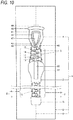
Fig. 10 is a plan view showing the waterproof slide fastener according to the first embodiment of the present invention. - As shown in
Fig. 10 , awaterproof slide fastener 1 according to a first embodiment of the present invention includes a pair of right andleft fastener stringers slider 3 movable forward and rearward to open and close the pair offastener stringers first stop 4 and a second stop 5 for stopping moving of theslider 3 on a respective one of front and rear limits of a moving range of theslider 3. - Directions are defined as follows. A "front and rear direction" is a direction, along which the pair of
fastener stringers Fig. 10 . The "front direction" is a direction, along which the pair offastener stringers Fig. 10 . The "rear direction" is a direction, along which the pair offastener stringers Fig. 10 . - A "right and left direction" is a right and left direction in
Fig. 10 . The "left direction" corresponds to the left direction inFig. 10 . The "right direction" corresponds to the right direction inFig. 10 . - An "up-down direction" is a thickness direction of the
fastener stringers 2 and corresponds to a direction perpendicular to the paper surface ofFig. 10 . The "up direction" is a direction which extends toward a near side with respect to the paper surface ofFig. 10 . The "down direction" is a direction which extends toward a far side with respect to the paper surface ofFig. 10 . - The pair of
fastener stringers tapes element rows tapes - Each of the
tapes 7 has the shape of a band elongated in the front and rear direction, and a thickness direction thereof is referred to as the up-down direction. Although not shown in detail, thetape 7 includes a tape main body made of a woven or knitted fabric, and a coating layer covering at least one surface, in the thickness direction, of the tape main body. For example, the coating layer may include a layer made of a thermoplastic elastomer, a layer, in which a water repelling layer made of a water repellent is formed on the thermoplastic elastomer layer, or a water repelling layer made of a water repellent formed instead of the thermoplastic elastomer layer. Therefore, thetape 7 has a waterproof property in the thickness direction. - Each of the
element rows 8 is formed by a plurality ofelements 9 fixed along a side edge portion of therespective tape 7, which faces the opposingtape 7, while being spaced from each other in the front and rear direction. More specifically, theelements 9 are formed by injection-molding on thetape 7. In a state where the pair offastener stringers elements 9 of one of the pair ofelement rows elements 9 of the other. In a state where the pair offastener stringers elements 9 of one of the pair ofelement rows elements 9 of the other in the right and left direction. - Each
element 9 includes abody portion 11 fixed to therespective tape 7 and extending in the right and left direction; aneck portion 12 protruding from a middle portion, in the front and rear direction, of thebody portion 11 toward the opposingtape 7; ahead portion 13 protruding from theneck portion 12 toward the opposingtape 7 and also bulging out in the front and rear direction; a pair ofshoulder portions neck portion 12; andfin portion 15 protruding from thebody portion 11 in a direction opposite to the opposingtape 7. In addition, twofin portions 15 are provided to be spaced in the front and rear direction. Also, the pair offin portions shoulder portions body portion 11. - Further, the pair of
fin portions body portion 11, the pair ofshoulder portions neck portion 12 are configured such that the opposing side edge portions of thetapes 7 are buried in middle portions thereof in the thickness direction. Therefore, theelements 9 are fixed on thetape 7 in such a manner to clamp thetape 7 from the top and bottom thereof. - The
head portion 13 has a groove (not shown) in a distal end surface thereof, which faces the opposingtape 7. The groove is opened toward the opposingtape 7 and also in the front and rear direction. In a state where theelements 9 are engaged with each other, a pair ofshoulder portions tape 7 are fitted in the groove. Further, it is theslider 3 which causes theelements 9 to be engaged with and disengaged from each other. - As shown in
Figs 1 to 3C , theslider 3 is configured to be moved along the pair ofelement rows slider 3 includes aslider body 17 configured to be engaged with the pair ofelement rows slider body 17. - The
slider body 17 includes anupper blade 18 and alower blade 19 arranged to be spaced from and oppose each other in the up-down direction; a connectingpost 21 connecting theupper blade 18 with thelower blade 19; an upper and lower right and leftflanges upper blade 18 and thelower blade 19 in a direction narrowing a gap therebetween; and apull attachment portion 23 protruding from an upper surface of theupper blade 18. - The
pull attachment portion 23 and theupper blade 18 cooperate with each other to define a through hole (not shown) allowing the pull to be attached. - The connecting
post 21 extends in the up-down direction and connects theupper blade 18 with thelower blade 19 at middle portions, in the right and left direction, of front portions thereof. The connectingpost 21 is positioned between the pair ofelement rows - As shown in
Fig. 8 , theflanges 22 are formed to be in close contact with thebody portions 11 of the right and leftelements 9 located at the most front side when theslider 3 is positioned at a forward limit position (closing limit position). - As shown in
Figs. 1 and 2 , in addition to tangible components, such as theupper blade 18, thelower blade 19, the connectingpost 21, theflanges 22 and thepull attachment portion 23, theslider body 17 includes anelement passage 25 allowing the pair ofelement rows tape grooves tapes - The
element passage 25 has a so-called Y-shape, in which theelement passage 25 is divided by the connectingpost 21 into right and left sides to separately extend forward and is merged at a rear side of the connectingpost 21 to extend rearward. Theelement passage 25 is delimited by theupper blade 18 and thelower blade 19 in the up-down direction, delimited by the upper and lower right and leftflanges 22 in the right and left direction and also delimited by the connectingpost 21 at a front middle portion thereof. - Each of the
tape grooves 26 is delimited by the opposing upper andlower flanges element passage 25 and the external space of theslider body 17 in the right and left direction. - The
upper blade 18 and thelower blade 19 have a symmetrical configuration in the up-down direction. Hereinafter, theupper blade 18 will be described in detail and thelower blade 19 will be briefly described. As shown inFigs. 2 and3 , theupper blade 18 includes amain blade portion 18a extending further rearward than a front end of the connectingpost 21, and anextension portion 18b extending forward from themain blade portion 18a. Similarly, thelower blade 19 includes amain blade portion 19a and anextension portion 19b. - A lower surface of the
main blade portion 18a of the upper blade 18 (surface thereof facing the lower blade 19) is a flat surface perpendicular to the up-down direction. An upper surface of the main blade portion19a of the lower blade 19 (surface thereof facing the upper blade 18) is also a flat surface perpendicular to the up-down direction. - The
extension portion 18b of theupper blade 18 includes amain extension portion 18c extending forward from a front end of themain blade portion 18a, and aprotrusion 18d located in front of the connectingpost 21 and protruding in the down direction from a front portion of themain extension portion 18c. Similarly, theextension portion 19b of thelower blade 19 includes amain extension portion 19c and aprotrusion 19d protruding in the up direction from a front portion of themain extension portion 19c. Themain extension portions protrusions - A rear portion of a lower surface of the
main extension portion 18c of theupper blade 18 is a flat surface continuous to the lower surface of themain blade portion 18a of theupper blade 18. On the other hand, a front portion of the lower surface of themain extension portion 18c of the upper blade 18 (a front edge portion of the lower surface of the upper blade 18) is aninclined surface 18e inclined in an up direction as it goes forward (i.e., an inclined surface inclined in the up direction as it goes forward based on the front and rear direction). Theinclined surface 18e not only extends in the right and left direction, but also extends rearward from right and left ends of theupper blade 18 toward the right and leftflanges Fig. 3A to 3C , the right and leftflanges upper blade 18. Therefore, right and left ends of theinclined surface 18e are configured to extend in the front and rear direction from the front end of theupper blade 18 to a front end of therespective flanges 22. Further, a middle portion, in the right and left direction, of theinclined surface 18e is positioned in front of the connectingpost 21, and theprotrusion 18d of theupper blade 18 protrudes from the middle portion. As a result, the lower surface of themain extension portion 18c of theupper blade 18 is provided withinclined surfaces protrusion 18d. On the other hand, in the example ofFig. 3A to 3C , theprotrusion 18d is formed over a range from the rear of the front end of themain extension portion 18c to the front end of themain blade portion 18a. That is, in the example ofFig. 3A to 3C , a distance D is formed between a front end of theprotrusion 18d and the front end of theupper blade 18, and a front end position of theprotrusion 18d of theupper blade 18 is a rear end position of the distance D (i.e., at the rear of the front end of the upper blade 18). - Similarly, a rear portion of the upper surface of the
main extension portion 19c of thelower blade 19 is a flat surface continuous to the upper surface of themain blade portion 19a of theupper blade 19. On the other hand, a front portion of the upper surface of themain extension portion 19c of the lower blade 19 (a front edge portion of the upper surface of the lower blade 19) is similarly aninclined surface 19e inclined in the down direction as it goes forward (i.e., an inclined surface inclined in the down direction as it goes forward based on the front and rear direction). Similarly, theprotrusion 19d of thelower blade 19 protrudes from a middle portion, in the right and left direction, of theinclined surface 19e. Also, the upper surface of themain extension portion 19c of thelower blade 19 is provided withinclined surfaces protrusion 19d. In the example ofFig. 3A to 3C , theprotrusion 19d is similarly formed over a range from the rear of the front end of themain extension portion 19c to the front end of themain blade portion 19a. That is, in the example ofFig. 3A to 3C , a front end position of theprotrusion 19d of thelower blade 19 is a rear end position of a distance D (i.e., at the rear of the front end of the lower blade 19). - Further, the right and left
inclined surfaces upper blade 18 and thelower blade 19 are inclined in a direction widening a gap therebetween in the up-down direction as they go forward, thereby facilitating guiding of theelements 9 into theelement passage 25 of theslider 3 when theslider 3 is moved forward. On the other hand, the details of the opposing surfaces of theupper blade 18 and thelower blade 19 will be described together with a configuration of thefirst stop 4. - A
left surface 18f of theprotrusion 18d of theupper blade 18 is an inclined surface extending in the left direction as it goes rearward. Similarly, aright surface 18f of theprotrusion 18d of theupper blade 18 is an inclined surface extending in the right direction as it goes rearward. That is, the right and leftsurfaces upper blade 18 are inclined surfaces inclined outside in the right and left direction as they go rearward. Similarly, right and leftsurfaces protrusion 19d of thelower blade 19 are inclined surfaces inclined outside in the right and left direction as they go rearward. - It is the
first stop 4 which stops moving of theslider 3 forward as described above and thus defines a forward limit position of a moving range of theslider 3. - As shown in
Figs. 8 and10 , thefirst stop 4 is fixed on a closed end of the pair offastener stringers tapes first stop 4 is fixed on the pair oftapes element rows 8 to be spaced from theelement rows 8. - The
first stop 4 is a resin having rubber elasticity, such as a thermoplastic elastomer, and is elastically deformable by rubber elasticity. Thefirst stop 4 includes anannular receiving body 41 configured to be opened and closed and also to receive the connectingpost 21 of theslider 3 to allow the connectingpost 21 to enter and exit; a pair of close-contact walls body 41 and also to come in close contact with the opposing surfaces of theupper blade 18 and thelower blade 19 over the entire annular circumference of the receivingbody 41; and upper and lower right and left sub-close-contact walls 43 as right and left side edge portions of a rear portion of the receivingportion 41 configured to be raised from both surfaces (upper and lower surfaces), in the thickness direction, of the receivingbody 41 and also to come in close contact with right and left inner surfaces of the upper and lower right and leftflanges first stop 4 includes a pair of raisedportions body 41 configured to be raised from both surfaces (upper and lower surfaces), in the thickness direction, of the receivingbody 41 in front of the pair of close-contact walls portion 46 configured to be bulged forward from a portion of a front surface of the receivingbody 41, which is positioned on the side of one surface (lower surface), in the thickness direction, of the receivingbody 41. - The receiving
body 41 is configured such that the opposing side edge portions of the pair oftapes tapes body 41 is configured to cover both upper and lower surfaces of the pair oftapes tapes body 41 has an annular shape surrounding around the connectingpost 21. Further, apost receiving hole 47 for receiving the connectingpost 21 is formed inside the receivingbody 41 to extend therethrough in the up-down direction. Further, on a rear portion of the receivingbody 41, anentrance portion 48 is formed to be opened and closed, thereby allowing the connectingpost 21 to enter and exit thepost receiving hole 47. The receivingbody 41 can be opened and closed by rubber elasticity of thefirst stop 4, in such a manner that when theentrance portion 48 is opened, a passage leading to thepost receiving hole 47 is formed and when theentrance portion 48 is closed, theentrance portion 48 is in close contact in the right and left direction. - In addition, the pair of
tapes portion 46. - The pair of close-
contact walls container 41 in a circumferential direction thereof and are formed to protrude from portions of both the upper and lower surfaces of the receivingbody 41, which correspond to middle portions thereof in an inward and outward direction (width direction) with respect to the annular shape. Also, as shown inFig. 8 , each of the close-contact walls 42 includes a transversal wall portion 42a extending in the right and left direction in front of the connectingpost 21; right and leftlongitudinal walls wall portions longitudinal walls upper blade 18 and thelower blade 19 sandwich the pair of close-contact walls contact walls - As shown in
Fig. 3A , the lower surface of the upper blade 18 (surface thereof opposing the lower blade 19) includes a close-contact surface 18h configured to come in close contact with the top surface of thefirst stop 4 located around the connectingpost 21 when theslider 3 is positioned at the forward limit position (closing limit position) and right and leftinclined surfaces contact surface 18h; and an extended close-contact surface 18i located between the right and leftinclined surfaces contact surface 18h. In addition, the close-contact surface 18h and the extended close-contact surface 18i are the flat surface of theupper blade 18 as described above (i.e., the flat surface perpendicular to the up-down direction). Similarly, as shown inFig. 3B , the upper surface of the lower blade 19 (surface thereof opposing the upper blade 18) includes a close-contact surface 19h, right and leftinclined surfaces contact surface 19i. Further, the close-contact surface 19h and the extended close-contact surface 19i are the flat surface of thelower blade 19 as described above (i.e., the flat surface perpendicular to the up-down direction). - The close-
contact surface 18h of theupper blade 18 has an annular shape surrounding around the connectingpost 21 and is represented by a range surrounded by a dotted line inFig. 3A . Assuming that the close-contact surface 18h is constructed by front and rear portions thereof relative to the front end of the connectingpost 21 as a reference position in the front and rear direction, the close-contact surface 18h is constructed by a front close-contact surface 18j, which is the front portion of the close-contact surface 18h, and a rear close-contact surface 18k, which is the rear portion of the close-contact surface 18h. - The front close-
contact surface 18j of theupper blade 18 is configured to come in close contact with a portion of the upper close-contact wall 42 of thefirst stop 4, which is located around the connectingpost 21 and in front of the front end of the connectingpost 21. On the other hand, the rear close-contact surface 18k of theupper blade 18 is configured to come in close contact with a portion of the upper close-contact wall 42 of thefirst stop 4, which is located around the connectingpost 21 and in the rear of the front end of the connectingpost 21. - Similarly, the close-
contact surface 19h of thelower blade 19 has an annular shape and is represented by a range surrounded by a dotted line inFig. 3B . Similarly, the close-contact surface 19h is constructed by a front close-contact surface 19j and a rear close-contact surface 19k. - The upper and lower front close-
contact surfaces contact walls 42 of thefirst stop 4, which are located around the connectingpost 21 and in front of the front end of the connectingpost 21, thereby sandwiching the pair of close-contact walls contact surfaces contact walls 42 of thefirst stop 4, which are located around the connectingpost 21 and in the rear of the front end of the connectingpost 21, thereby sandwiching the pair of close-contact walls - The extended close-
contact surface 18i of theupper blade 18 is a lower surface of theprotrusion 18d of theupper blade 18 and extends forward from the front close-contact surface 18j of theextension portion 18b of the upper blade 18 (i.e., the front close-contact surface 18j of the upper blade 18). Similarly, the extended close-contact surface 19i of thelower blade 19 is an upper surface of theprotrusion 19d of thelower blade 19 and extends forward from the front close-contact surface 19j of theextension portion 19b of the lower blade 19 (i.e., the front close-contact surface 19j of the lower blade 19). In addition, as shown inFig. 9 , right and left sides of the extended close-contact surface 19i of thelower blade 19 coincide with the right and leftsurfaces protrusion 19d of thelower blade 19 and have a shape extending outside in the right and left direction as they go rearward. Also, both right and left ends of a front side of the extended close-contact surface 19i of thelower blade 19 are located more outside in the right and left direction than anextension line 42L of an inner side of each of the right and leftlongitudinal wall portions 42b of the close-contact wall 42. When theslider 3 including the upper and lower extended close-contact surfaces slider 3 collides against the second stop 5. - As shown in
Fig. 10 , the first stop 5 is fixed on the rear of the pair ofelement rows tapes tapes elements 9, thereby allowing a rear surface of theslider 3 to collide thereagainst. On the other hand, the second stop 5 is also made of resin and is formed by injection molding. - According to the
waterproof slide fastener 1 and theslider 3 of the first embodiment of the present invention, theslider 3 has the close-contact surfaces Figs. 4 ,6 and8 , when theslider 3 is positioned at the closing limit position, the close-contact surface 18h of theupper blade 18 and the close-contact surface 19h of thelower blade 19 in the vicinity of the connectingpost 21 are respectively in close contact with the upper and lower close-contact walls first stop 4, thereby exhibiting a waterproof effect. Further, theslider 3 has the extended close-contact surfaces Figs. 5 ,7 and9 , even when theslider 3 is positioned slightly rearward from the closing limit position, the close-contact surfaces contact surfaces upper blade 18 and thelower blade 19 in the vicinity of the connectingpost 21 can be respectively in close contact with the upper and lower close-contact walls first stop 4, thereby exhibiting a waterproof effect. In addition, theslider 3 has the upper and lower extended close-contact surfaces - Also, according to the
waterproof slide fastener 1 and theslider 3 of the first embodiment of the present invention, the right and leftsurfaces protrusions slider 3 are inclined surfaces extending outside in the right and left direction as they go rearward. Therefore, if the pair offastener stringers slider 3 forward under a situation where theslider 3 is positioned at a location other than both front and rear ends of the pair ofelement rows Fig. 10 (on a middle portion of the entire length thereof), it is possible to facilitate guiding of the pair ofelement rows element rows post 21 as they go from the front end side of theslider 3, which is close to thefirst stop 4, toward the rear side of theslider 3. Further, theslider 3 has the upper andlower protrusions surfaces lower protrusions - The present invention is not limited to the foregoing embodiments, but may be appropriately modified without departing from the spirit and scope thereof.
- For example, although, in the foregoing embodiments, the front end of the
protrusion 18d of theupper blade 18 is located at the rear of the front end of theupper blade 18, the present invention is not limited thereto. The front end of theprotrusion 18d may be located to coincide with the front end of theupper blade 18. Theprotrusion 19d of thelower blade 19 may also be configured in a similar manner. - Further, although in the foregoing embodiments, the
slider 3 is configured to have the upper andlower protrusions lower protrusions -
- 1
- Waterproof Slide Fastener
- 2
- Fastener Stringer
- 3
- Slider
- 4
- First Stop
- 5
- Second Stop
- 7
- Tape
- 8
- Element Row
- 9
- Element
- 11
- Body Portion
- 12
- Neck Portion
- 13
- Head Portion
- 14
- Shoulder Portion
- 15
- Fin Portion
- 17
- Slider Body
- 18
- Upper Blade
- 18a
- Main Blade Portion
- 18b
- Extension Portion
- 18c
- Main Extension Portion
- 18d
- Protrusion
- 18e
- Inclined Surface
- 18f
- Surface
- 18h
- Close-Contact Surface
- 18i
- Extended Close-Contact Surface
- 18j
- Front Close-Contact Surface
- 18k
- Rear Close-Contact Surface
- 19
- lower Blade
- 19a
- Main Blade Portion
- 19b
- Extension Portion
- 19c
- Main Extension Portion
- 19d
- Protrusion
- 19e
- Inclined Surface
- 19f
- Surface
- 19h
- Close-Contact Surface
- 19i
- Extended Close-Contact Surface
- 19j
- Front Close-Contact Surface
- 19k
- Rear Close-Contact Surface
- 21
- Connecting Post
- 22
- Flange
- 23
- Pull Attachment Portion
- 25
- Element Passage
- 26
- Tape groove
- 41
- Receiving Body
- 42
- Close-Contact Wall
- 42a
- Transversal Wall Portion
- 42b
- Longitudinal Wall Portion
- 42c
- Approaching Wall Portion
- 42L
- Extension Line
- 43
- Sub-Close-Contact Wall
- 45
- Raised Portion
- 46
- Bulged Portion
- 47
- Post Receiving Hole
- 48
- Entrance Portion
- D
- Distance
Claims (5)
- A slider (3) for a waterproof slide fastener (1), wherein the slider (3) is configured to be stopped to move forward by a first stop (4) arranged on a front end of each of right and left fastener stringers (2, 2) being capable of opened and closed, the fastener stringers (2, 2) are closed when the slider (3) is at the front end, and the slider (3) is configured to sandwich and come in close contact with the first stop (4) in an up-down direction of the slider (3), the slider (3) comprising:an upper blade (18) and a lower blade (19) opposing each other in the up-down direction; anda connecting post (21) connecting the upper blade (18) with the lower blade (19), whereinan element passage (25) is divided by the connecting post (21) into right and left sides to separately extend forward, and is merged at a rear side of the connecting post (21) to extend rearward,each of opposing surfaces of the upper blade (18) and the lower blade (19) includes a close-contact surface (18h, 19h) provided around the connecting post (21) and configured to sandwich and come in close contact with the first stop (4) in the up-down direction, andat least one of the opposing surfaces includes right and left inclined surfaces (18e, 18e, 19e, 19e) provided respectively on right and left sides at a front side of the close-contact surface (18h, 19h) and inclined in a direction widening a gap between the upper blade (18) and the lower blade (19) as the right and left inclined surfaces go forward, andthe at least one of the opposing surfaces includes an extended close-contact surface (18i, 19i) provided between the right and left inclined surfaces (18e, 18e, 19e, 19e) and extending forward from the close-contact surface (18h, 19h).
- The slider (3) for a waterproof slide fastener (1) according to claim 1, wherein
each of the upper blade (18) and the lower blade (19) includes a main blade portion (18a, 19a) extending rearward than a front end of the connecting post (21) and an extension portion (18b, 19b) extending forward from the main blade portion (18a, 19a),
each of the upper and lower extension portions (18b, 19b) includes a main extension portion (18c, 19c) inclined in a front portion of the main extension portion (18c, 19c) in a direction widening a gap between the upper blade (18) and the lower blade (19) as the main extension portion (18c, 19c) goes forward and being parallel to each other in a rear portion of the main extension portion (18c, 19c) to equalize the gap, and a protrusion (18d, 19d) provided in front of the connecting post (21) and protruding from a front portion of at least one of the upper and lower main extension portions (18c, 19c) in a direction narrowing a gap between the upper blade (18) and the lower blade (19),
each of the upper and lower main extension portions (18c, 19c) includes the right and left inclined surfaces (18e, 18e, 19e, 19e) and a front close-contact surface (18j, 19j), which is a front portion of the close-contact surface (18h, 19h),
each of the protrusions (18d, 19d) includes the extended close-contact surface (18i, 19i), and
the extended close-contact surface (18i, 19i) extends forward from the front close-contact surface (18j, 19j) of the extension portion (18b, 19b) from which each of the protrusions (18d, 19d) protrudes. - The slider (3) for a waterproof slide fastener (1) according to claim 2, wherein
each of the upper blade (18) and the lower blade (19) includes the protrusion (18d, 19d), and
each of the opposing surfaces of the upper blade (18) and the lower blade (19) includes the extended close-contact surface (18i, 19i). - The slider (3) for a waterproof slide fastener (1) according to claim 2 or 3, wherein
the right and left surfaces (18f, 18f, 19f, 19f) of the protrusions (18d, 19d) are inclined surfaces extending outside in a right and left direction of slider (3) as the right and left surfaces (18f, 18f, 19f, 19f) go rearward. - A waterproof slide fastener (1), comprising:a pair of fastener stringers (2, 2) including a pair of tapes (7, 7) extending in a front and rear direction and arranged adjacent to each other in a right and left direction and a pair of element rows (8, 8) fixed along opposing side edge portions of the pair of tapes (7, 7);the slider (3) according to any one of claims 1 to 4; anda first stop (4) configured to coming in close contact with the slider (3) and stopping moving of the slider (3),and connecting the pair of tapes (7, 7) with each other in front of the pair of element rows (8, 8).
Applications Claiming Priority (1)
| Application Number | Priority Date | Filing Date | Title |
|---|---|---|---|
| JP2019199494A JP7339855B2 (en) | 2019-11-01 | 2019-11-01 | Waterproof slide fastener slider and waterproof slide fastener |
Publications (2)
| Publication Number | Publication Date |
|---|---|
| EP3815564A1 true EP3815564A1 (en) | 2021-05-05 |
| EP3815564B1 EP3815564B1 (en) | 2022-07-06 |
Family
ID=73037848
Family Applications (1)
| Application Number | Title | Priority Date | Filing Date |
|---|---|---|---|
| EP20204457.4A Active EP3815564B1 (en) | 2019-11-01 | 2020-10-28 | Slider for waterproof slide fastener and waterproof slide fastener |
Country Status (4)
| Country | Link |
|---|---|
| US (1) | US11185133B2 (en) |
| EP (1) | EP3815564B1 (en) |
| JP (1) | JP7339855B2 (en) |
| CN (1) | CN112773055B (en) |
Families Citing this family (2)
| Publication number | Priority date | Publication date | Assignee | Title |
|---|---|---|---|---|
| WO2025126466A1 (en) * | 2023-12-15 | 2025-06-19 | Ykk株式会社 | Slider of waterproof slide fastener |
| USD1094179S1 (en) * | 2023-12-22 | 2025-09-23 | Ideal Fastener (Guangdong) Industries Ltd. | Zipper slider |
Citations (2)
| Publication number | Priority date | Publication date | Assignee | Title |
|---|---|---|---|---|
| US20140259560A1 (en) * | 2013-03-14 | 2014-09-18 | Ykk Corporation Of America | Top stop for slider |
| WO2018069971A1 (en) | 2016-10-11 | 2018-04-19 | Ykk株式会社 | Waterproof slide fastener |
Family Cites Families (16)
| Publication number | Priority date | Publication date | Assignee | Title |
|---|---|---|---|---|
| US2923992A (en) * | 1955-08-15 | 1960-02-09 | Sealing closure | |
| JPS62181206U (en) * | 1986-05-06 | 1987-11-17 | ||
| BR9001653A (en) * | 1989-03-31 | 1991-05-07 | Yoshida Kogyo Kk | ZIPPER CURSOR |
| JPH0595807A (en) * | 1991-10-11 | 1993-04-20 | Yoshida Kogyo Kk <Ykk> | Slider for slide faster and its manufacturing method |
| JP3396346B2 (en) * | 1995-01-31 | 2003-04-14 | ワイケイケイ株式会社 | Slide fastener slider |
| JP2000262309A (en) * | 1999-03-17 | 2000-09-26 | Ykk Corp | Slide fastener slider |
| DE10030185B4 (en) * | 2000-06-20 | 2005-06-09 | Dynat Verschlußtechnik GmbH | Fluid-tight zipper |
| JP2002253307A (en) * | 2001-02-28 | 2002-09-10 | Ykk Corp | Top fastener of slide fastener |
| USD467523S1 (en) * | 2001-12-21 | 2002-12-24 | Yu-Pau Lin | Slide |
| JP4628233B2 (en) * | 2005-09-29 | 2011-02-09 | Ykk株式会社 | Top stopper for waterproofing of slide fastener |
| ES2361341T3 (en) * | 2007-05-16 | 2011-06-16 | Riri Sa | FLUID WRAPPED ZIPPER. |
| US9314069B2 (en) * | 2011-07-20 | 2016-04-19 | Ykk Corporation | Top stop for slider |
| CN105530829B (en) * | 2013-07-09 | 2019-11-08 | Ykk株式会社 | Zipper slider and zipper |
| US9538817B2 (en) * | 2014-07-22 | 2017-01-10 | Ykk Corporation | Sealing for open-end slide fastener |
| US11109650B2 (en) * | 2014-12-04 | 2021-09-07 | Nite Ize, Inc. | Systems and methods for improved zipper slider garage |
| US10531712B2 (en) * | 2016-10-03 | 2020-01-14 | Ykk Corporation | Sealing for open-end slide fasteners |
-
2019
- 2019-11-01 JP JP2019199494A patent/JP7339855B2/en active Active
-
2020
- 2020-10-23 US US17/079,170 patent/US11185133B2/en active Active
- 2020-10-28 EP EP20204457.4A patent/EP3815564B1/en active Active
- 2020-10-30 CN CN202011187765.2A patent/CN112773055B/en active Active
Patent Citations (2)
| Publication number | Priority date | Publication date | Assignee | Title |
|---|---|---|---|---|
| US20140259560A1 (en) * | 2013-03-14 | 2014-09-18 | Ykk Corporation Of America | Top stop for slider |
| WO2018069971A1 (en) | 2016-10-11 | 2018-04-19 | Ykk株式会社 | Waterproof slide fastener |
Also Published As
| Publication number | Publication date |
|---|---|
| JP2021069822A (en) | 2021-05-06 |
| EP3815564B1 (en) | 2022-07-06 |
| US11185133B2 (en) | 2021-11-30 |
| US20210127798A1 (en) | 2021-05-06 |
| JP7339855B2 (en) | 2023-09-06 |
| CN112773055A (en) | 2021-05-11 |
| CN112773055B (en) | 2022-11-01 |
Similar Documents
| Publication | Publication Date | Title |
|---|---|---|
| US11134756B2 (en) | Waterproof slide fastener | |
| US4524493A (en) | Watertight slide fastener | |
| CA2541717C (en) | Top end stops for slide fastener | |
| CN102892325B (en) | Slide fastener | |
| US9968166B2 (en) | Slider cover for slide fastener | |
| US9314069B2 (en) | Top stop for slider | |
| EP3815564B1 (en) | Slider for waterproof slide fastener and waterproof slide fastener | |
| EP2904922B1 (en) | Slide fastener | |
| US20130139364A1 (en) | Slide Fastener | |
| JP7001812B2 (en) | Slide fastener | |
| WO2018225264A1 (en) | Sliding fastener | |
| US4521942A (en) | Lockable slide fastener slider | |
| CN222639884U (en) | Slider of waterproof slide fastener | |
| TWI556763B (en) | Zipper stopper | |
| JP2015070961A (en) | Slider for slide fastener and slider set | |
| GB2574965A (en) | Slide fastener | |
| HK1092337B (en) | Top end stops for slide fastener | |
| HK1191190B (en) | Slide fastener |
Legal Events
| Date | Code | Title | Description |
|---|---|---|---|
| PUAI | Public reference made under article 153(3) epc to a published international application that has entered the european phase |
Free format text: ORIGINAL CODE: 0009012 |
|
| STAA | Information on the status of an ep patent application or granted ep patent |
Free format text: STATUS: REQUEST FOR EXAMINATION WAS MADE |
|
| 17P | Request for examination filed |
Effective date: 20201102 |
|
| AK | Designated contracting states |
Kind code of ref document: A1 Designated state(s): AL AT BE BG CH CY CZ DE DK EE ES FI FR GB GR HR HU IE IS IT LI LT LU LV MC MK MT NL NO PL PT RO RS SE SI SK SM TR |
|
| GRAP | Despatch of communication of intention to grant a patent |
Free format text: ORIGINAL CODE: EPIDOSNIGR1 |
|
| STAA | Information on the status of an ep patent application or granted ep patent |
Free format text: STATUS: GRANT OF PATENT IS INTENDED |
|
| INTG | Intention to grant announced |
Effective date: 20220222 |
|
| GRAS | Grant fee paid |
Free format text: ORIGINAL CODE: EPIDOSNIGR3 |
|
| GRAA | (expected) grant |
Free format text: ORIGINAL CODE: 0009210 |
|
| STAA | Information on the status of an ep patent application or granted ep patent |
Free format text: STATUS: THE PATENT HAS BEEN GRANTED |
|
| AK | Designated contracting states |
Kind code of ref document: B1 Designated state(s): AL AT BE BG CH CY CZ DE DK EE ES FI FR GB GR HR HU IE IS IT LI LT LU LV MC MK MT NL NO PL PT RO RS SE SI SK SM TR |
|
| REG | Reference to a national code |
Ref country code: AT Ref legal event code: REF Ref document number: 1502217 Country of ref document: AT Kind code of ref document: T Effective date: 20220715 Ref country code: CH Ref legal event code: EP |
|
| REG | Reference to a national code |
Ref country code: DE Ref legal event code: R096 Ref document number: 602020003882 Country of ref document: DE |
|
| REG | Reference to a national code |
Ref country code: IE Ref legal event code: FG4D |
|
| REG | Reference to a national code |
Ref country code: LT Ref legal event code: MG9D |
|
| REG | Reference to a national code |
Ref country code: NL Ref legal event code: MP Effective date: 20220706 |
|
| PG25 | Lapsed in a contracting state [announced via postgrant information from national office to epo] |
Ref country code: SE Free format text: LAPSE BECAUSE OF FAILURE TO SUBMIT A TRANSLATION OF THE DESCRIPTION OR TO PAY THE FEE WITHIN THE PRESCRIBED TIME-LIMIT Effective date: 20220706 Ref country code: RS Free format text: LAPSE BECAUSE OF FAILURE TO SUBMIT A TRANSLATION OF THE DESCRIPTION OR TO PAY THE FEE WITHIN THE PRESCRIBED TIME-LIMIT Effective date: 20220706 Ref country code: PT Free format text: LAPSE BECAUSE OF FAILURE TO SUBMIT A TRANSLATION OF THE DESCRIPTION OR TO PAY THE FEE WITHIN THE PRESCRIBED TIME-LIMIT Effective date: 20221107 Ref country code: NO Free format text: LAPSE BECAUSE OF FAILURE TO SUBMIT A TRANSLATION OF THE DESCRIPTION OR TO PAY THE FEE WITHIN THE PRESCRIBED TIME-LIMIT Effective date: 20221006 Ref country code: NL Free format text: LAPSE BECAUSE OF FAILURE TO SUBMIT A TRANSLATION OF THE DESCRIPTION OR TO PAY THE FEE WITHIN THE PRESCRIBED TIME-LIMIT Effective date: 20220706 Ref country code: LV Free format text: LAPSE BECAUSE OF FAILURE TO SUBMIT A TRANSLATION OF THE DESCRIPTION OR TO PAY THE FEE WITHIN THE PRESCRIBED TIME-LIMIT Effective date: 20220706 Ref country code: LT Free format text: LAPSE BECAUSE OF FAILURE TO SUBMIT A TRANSLATION OF THE DESCRIPTION OR TO PAY THE FEE WITHIN THE PRESCRIBED TIME-LIMIT Effective date: 20220706 Ref country code: FI Free format text: LAPSE BECAUSE OF FAILURE TO SUBMIT A TRANSLATION OF THE DESCRIPTION OR TO PAY THE FEE WITHIN THE PRESCRIBED TIME-LIMIT Effective date: 20220706 Ref country code: ES Free format text: LAPSE BECAUSE OF FAILURE TO SUBMIT A TRANSLATION OF THE DESCRIPTION OR TO PAY THE FEE WITHIN THE PRESCRIBED TIME-LIMIT Effective date: 20220706 |
|
| REG | Reference to a national code |
Ref country code: AT Ref legal event code: MK05 Ref document number: 1502217 Country of ref document: AT Kind code of ref document: T Effective date: 20220706 |
|
| PG25 | Lapsed in a contracting state [announced via postgrant information from national office to epo] |
Ref country code: PL Free format text: LAPSE BECAUSE OF FAILURE TO SUBMIT A TRANSLATION OF THE DESCRIPTION OR TO PAY THE FEE WITHIN THE PRESCRIBED TIME-LIMIT Effective date: 20220706 Ref country code: IS Free format text: LAPSE BECAUSE OF FAILURE TO SUBMIT A TRANSLATION OF THE DESCRIPTION OR TO PAY THE FEE WITHIN THE PRESCRIBED TIME-LIMIT Effective date: 20221106 Ref country code: HR Free format text: LAPSE BECAUSE OF FAILURE TO SUBMIT A TRANSLATION OF THE DESCRIPTION OR TO PAY THE FEE WITHIN THE PRESCRIBED TIME-LIMIT Effective date: 20220706 Ref country code: GR Free format text: LAPSE BECAUSE OF FAILURE TO SUBMIT A TRANSLATION OF THE DESCRIPTION OR TO PAY THE FEE WITHIN THE PRESCRIBED TIME-LIMIT Effective date: 20221007 |
|
| REG | Reference to a national code |
Ref country code: DE Ref legal event code: R097 Ref document number: 602020003882 Country of ref document: DE |
|
| PG25 | Lapsed in a contracting state [announced via postgrant information from national office to epo] |
Ref country code: SM Free format text: LAPSE BECAUSE OF FAILURE TO SUBMIT A TRANSLATION OF THE DESCRIPTION OR TO PAY THE FEE WITHIN THE PRESCRIBED TIME-LIMIT Effective date: 20220706 Ref country code: RO Free format text: LAPSE BECAUSE OF FAILURE TO SUBMIT A TRANSLATION OF THE DESCRIPTION OR TO PAY THE FEE WITHIN THE PRESCRIBED TIME-LIMIT Effective date: 20220706 Ref country code: DK Free format text: LAPSE BECAUSE OF FAILURE TO SUBMIT A TRANSLATION OF THE DESCRIPTION OR TO PAY THE FEE WITHIN THE PRESCRIBED TIME-LIMIT Effective date: 20220706 Ref country code: CZ Free format text: LAPSE BECAUSE OF FAILURE TO SUBMIT A TRANSLATION OF THE DESCRIPTION OR TO PAY THE FEE WITHIN THE PRESCRIBED TIME-LIMIT Effective date: 20220706 Ref country code: AT Free format text: LAPSE BECAUSE OF FAILURE TO SUBMIT A TRANSLATION OF THE DESCRIPTION OR TO PAY THE FEE WITHIN THE PRESCRIBED TIME-LIMIT Effective date: 20220706 |
|
| PLBE | No opposition filed within time limit |
Free format text: ORIGINAL CODE: 0009261 |
|
| STAA | Information on the status of an ep patent application or granted ep patent |
Free format text: STATUS: NO OPPOSITION FILED WITHIN TIME LIMIT |
|
| PG25 | Lapsed in a contracting state [announced via postgrant information from national office to epo] |
Ref country code: SK Free format text: LAPSE BECAUSE OF FAILURE TO SUBMIT A TRANSLATION OF THE DESCRIPTION OR TO PAY THE FEE WITHIN THE PRESCRIBED TIME-LIMIT Effective date: 20220706 Ref country code: MC Free format text: LAPSE BECAUSE OF FAILURE TO SUBMIT A TRANSLATION OF THE DESCRIPTION OR TO PAY THE FEE WITHIN THE PRESCRIBED TIME-LIMIT Effective date: 20220706 Ref country code: EE Free format text: LAPSE BECAUSE OF FAILURE TO SUBMIT A TRANSLATION OF THE DESCRIPTION OR TO PAY THE FEE WITHIN THE PRESCRIBED TIME-LIMIT Effective date: 20220706 |
|
| 26N | No opposition filed |
Effective date: 20230411 |
|
| P01 | Opt-out of the competence of the unified patent court (upc) registered |
Effective date: 20230428 |
|
| REG | Reference to a national code |
Ref country code: BE Ref legal event code: MM Effective date: 20221031 |
|
| PG25 | Lapsed in a contracting state [announced via postgrant information from national office to epo] |
Ref country code: LU Free format text: LAPSE BECAUSE OF NON-PAYMENT OF DUE FEES Effective date: 20221028 Ref country code: AL Free format text: LAPSE BECAUSE OF FAILURE TO SUBMIT A TRANSLATION OF THE DESCRIPTION OR TO PAY THE FEE WITHIN THE PRESCRIBED TIME-LIMIT Effective date: 20220706 |
|
| PG25 | Lapsed in a contracting state [announced via postgrant information from national office to epo] |
Ref country code: FR Free format text: LAPSE BECAUSE OF NON-PAYMENT OF DUE FEES Effective date: 20221031 |
|
| PG25 | Lapsed in a contracting state [announced via postgrant information from national office to epo] |
Ref country code: SI Free format text: LAPSE BECAUSE OF FAILURE TO SUBMIT A TRANSLATION OF THE DESCRIPTION OR TO PAY THE FEE WITHIN THE PRESCRIBED TIME-LIMIT Effective date: 20220706 |
|
| PG25 | Lapsed in a contracting state [announced via postgrant information from national office to epo] |
Ref country code: BE Free format text: LAPSE BECAUSE OF NON-PAYMENT OF DUE FEES Effective date: 20221031 |
|
| PG25 | Lapsed in a contracting state [announced via postgrant information from national office to epo] |
Ref country code: IE Free format text: LAPSE BECAUSE OF NON-PAYMENT OF DUE FEES Effective date: 20221028 |
|
| PG25 | Lapsed in a contracting state [announced via postgrant information from national office to epo] |
Ref country code: IT Free format text: LAPSE BECAUSE OF FAILURE TO SUBMIT A TRANSLATION OF THE DESCRIPTION OR TO PAY THE FEE WITHIN THE PRESCRIBED TIME-LIMIT Effective date: 20220706 |
|
| PG25 | Lapsed in a contracting state [announced via postgrant information from national office to epo] |
Ref country code: CY Free format text: LAPSE BECAUSE OF FAILURE TO SUBMIT A TRANSLATION OF THE DESCRIPTION OR TO PAY THE FEE WITHIN THE PRESCRIBED TIME-LIMIT Effective date: 20220706 |
|
| PG25 | Lapsed in a contracting state [announced via postgrant information from national office to epo] |
Ref country code: MK Free format text: LAPSE BECAUSE OF FAILURE TO SUBMIT A TRANSLATION OF THE DESCRIPTION OR TO PAY THE FEE WITHIN THE PRESCRIBED TIME-LIMIT Effective date: 20220706 |
|
| REG | Reference to a national code |
Ref country code: CH Ref legal event code: PL |
|
| PG25 | Lapsed in a contracting state [announced via postgrant information from national office to epo] |
Ref country code: CH Free format text: LAPSE BECAUSE OF NON-PAYMENT OF DUE FEES Effective date: 20231031 |
|
| PG25 | Lapsed in a contracting state [announced via postgrant information from national office to epo] |
Ref country code: HU Free format text: LAPSE BECAUSE OF FAILURE TO SUBMIT A TRANSLATION OF THE DESCRIPTION OR TO PAY THE FEE WITHIN THE PRESCRIBED TIME-LIMIT; INVALID AB INITIO Effective date: 20201028 Ref country code: CH Free format text: LAPSE BECAUSE OF NON-PAYMENT OF DUE FEES Effective date: 20231031 Ref country code: BG Free format text: LAPSE BECAUSE OF FAILURE TO SUBMIT A TRANSLATION OF THE DESCRIPTION OR TO PAY THE FEE WITHIN THE PRESCRIBED TIME-LIMIT Effective date: 20220706 |
|
| PG25 | Lapsed in a contracting state [announced via postgrant information from national office to epo] |
Ref country code: MT Free format text: LAPSE BECAUSE OF FAILURE TO SUBMIT A TRANSLATION OF THE DESCRIPTION OR TO PAY THE FEE WITHIN THE PRESCRIBED TIME-LIMIT Effective date: 20220706 |
|
| GBPC | Gb: european patent ceased through non-payment of renewal fee |
Effective date: 20241028 |
|
| PG25 | Lapsed in a contracting state [announced via postgrant information from national office to epo] |
Ref country code: GB Free format text: LAPSE BECAUSE OF NON-PAYMENT OF DUE FEES Effective date: 20241028 |
|
| PG25 | Lapsed in a contracting state [announced via postgrant information from national office to epo] |
Ref country code: TR Free format text: LAPSE BECAUSE OF FAILURE TO SUBMIT A TRANSLATION OF THE DESCRIPTION OR TO PAY THE FEE WITHIN THE PRESCRIBED TIME-LIMIT Effective date: 20220706 |
|
| PGFP | Annual fee paid to national office [announced via postgrant information from national office to epo] |
Ref country code: DE Payment date: 20250902 Year of fee payment: 6 |