EP3815521A2 - Improvements relating to animal beds - Google Patents
Improvements relating to animal beds Download PDFInfo
- Publication number
- EP3815521A2 EP3815521A2 EP20175925.5A EP20175925A EP3815521A2 EP 3815521 A2 EP3815521 A2 EP 3815521A2 EP 20175925 A EP20175925 A EP 20175925A EP 3815521 A2 EP3815521 A2 EP 3815521A2
- Authority
- EP
- European Patent Office
- Prior art keywords
- cover
- bed
- core
- kit according
- support surface
- Prior art date
- Legal status (The legal status is an assumption and is not a legal conclusion. Google has not performed a legal analysis and makes no representation as to the accuracy of the status listed.)
- Granted
Links
Images



Classifications
-
- A—HUMAN NECESSITIES
- A01—AGRICULTURE; FORESTRY; ANIMAL HUSBANDRY; HUNTING; TRAPPING; FISHING
- A01K—ANIMAL HUSBANDRY; AVICULTURE; APICULTURE; PISCICULTURE; FISHING; REARING OR BREEDING ANIMALS, NOT OTHERWISE PROVIDED FOR; NEW BREEDS OF ANIMALS
- A01K1/00—Housing animals; Equipment therefor
- A01K1/02—Pigsties; Dog-kennels; Rabbit-hutches or the like
- A01K1/035—Devices for use in keeping domestic animals, e.g. fittings in housings or dog beds
- A01K1/0353—Pet beds, e.g. dog beds
Definitions
- This invention relates to improvements to animal beds, particularly but not exclusively to dog beds.
- One illustrative aspect of the invention relates to a kit for converting an animal bed into a raised animal bed.
- Another illustrative aspect of the invention relates to a cover for an animal bed, and a further aspect of the invention relates to an animal bed.
- Animal beds such as a dog bed for example, typically comprise a core and a removable cover for the core.
- a conventional floor-lying bed that is available from Omlet Ltd, Tuthill Park, Wardington, Oxfordshire OX17 1RR, United Kingdom is depicted in Fig. 1 .
- This dog bed comprises a padded core and a removable outer cover that includes a peripheral bolster. The cover can be taken off the core for cleaning in a washing machine.
- this illustrative dog bed provides a comfortable bed for a dog, it is the case that some dogs (and indeed their owners) prefer their beds to be elevated from the floor so that the bed is less likely to move around when the dog climbs on and off the bed.
- a kit for converting a floor-lying animal bed comprising a core and a cover into a raised animal bed
- the kit comprising: a support surface insertable into the animal bed so as to lie between the core and a part of the cover that forms the underside of the bed in use; a plurality of legs, and fixings for coupling the legs to the support surface through said part of the cover.
- the fixings may comprise screws.
- the screws may comprise double-ended screws.
- the support may include a plurality of retainers configured to cooperate with said fixings to couple said legs to the support.
- the retainers may comprise a plurality of captive nuts embedded in said support.
- the fixings may comprise bolts that can be coupled to said captive nuts.
- the cover has a plurality of through-holes provided in the part of the cover that forms the underside of the bed in use. This arrangement reduces the likelihood of the cover being damaged.
- each said through-hole is configured to align with a respective retainer in said support when said support has been inserted into the animal bed so as to lie between the core and the part of the cover that forms the underside of the bed in use.
- the cover may be reinforced in the vicinity of said through holes.
- the reinforcement may be provided by means of a plurality of eyelets.
- the core may comprise a padded body, a foam body or a bean bag.
- Another aspect of the present invention relates to a cover for an animal bed, said cover being configured and arranged for use with the kit described herein.
- a further aspect of the invention comprises a raised animal bed comprising a kit as described herein.
- a cover for an animal bed comprising a plurality of surfaces that cooperate to define an internal void for receiving an animal bed core, said cover being openable to enable access to be had to said void, the cover further comprising a plurality of through-holes provided in one said surface that forms the underside of the animal bed in use.
- the cover is reinforced in the vicinity of said through holes.
- the reinforcement may be provided by means of a plurality of eyelets, each said eyelet being associated with a respective one of said through-holes.
- a raised animal bed comprising a cover and a core
- said cover comprises a plurality of panels that cooperate to define an internal void, the cover being openable to permit the core to be inserted into said void, a panel of said cover that forms the underside of said animal bed in use including a plurality of through-holes;
- the bed further comprising a support surface locatable within said void between the core and the panel of the cover that forms the underside of the bed so that respective ones of a plurality of retainers provided in said support surface are aligned with respective through-holes in said cover, and a plurality of legs each having a leg fixing associated therewith, each leg fixing being insertable through a respective through-hole and into engagement with a respective retainer in said support surface to couple the legs to said support surface through the cover.
- the retainers comprise captive nuts embedded in said support surface and said fixings comprise bolts engageable with said nuts.
- FIG. 2 there is depicted a schematic representation of the underside of an illustrative conventional animal bed 1, in this instance a dog bed.
- the bed 1 has a generally rectangular footprint, but it will be appreciated that the shape of the bed may be varied as desired.
- the bed 1 comprises an outer cover 5, preferably of a fabric material, that defines an internal void within which an inner core 3 is enclosed.
- the core is compressible, but it needn't necessarily be so.
- the cover protects the core from damage and helps keep the core clean.
- a panel 7 forming the underside of the bed 1 is detachable (at least in part) from the remainder of the cover so that the core can be removed, and the cover can be cleaned. To that end, it is preferred for the cover to be machine-washable.
- the panel 7 Whilst it is preferred for the panel 7 to be provided on the underside of the bed 1, it will be appreciated that this is not essential and the panel could comprise a sidewall, or indeed the top wall, of the bed. Similarly, whilst it is preferred for the cover and core to be separable to enable the cover to be cleaned, it is only necessary for the core to be accessible in order to implement the teachings of the present invention.
- the panel 7 is preferably coupled to the remainder of the cover by means of a zip fastener that extends, in this arrangement around three sides of the panel.
- the panel 7 could be secured to the remainder of the cover by another type of fastener, for example buttons, press studs, a two-part mechanical hook and loop mechanism (such as VelcroTM) or by any of a variety of alternatives the like of which will be immediately apparent to persons of skill in the art.
- the inner core 3 comprises, in this example, a rectangular cuboid foam structure configured to fit within the cover 5. It will be appreciated, however, that a variety of different types of core could instead be provided.
- the core could comprise a padded body (akin to a pillow), memory foam, a bean bag or a variety of other alternatives the like of which will be immediately apparent to persons of skill in the art.
- the core is of a hypoallergenic material that may also include an appropriate biocide and/or stain resistant compound.
- kit 9 that embodies a first aspect of the present invention.
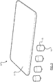
- the kit 9 is configured for converting the bed 1 of Fig. 2 into a raised bed and comprises a planar support surface 11 (for example of wood, plastics or other stiff material) that can be inserted into the bed 1 so that the support surface 11 lies between the core 3 and the outer cover 5, in one envisaged arrangement between the core 3 and the panel 7 of the cover that forms the underside of the bed 1.
- the kit further comprises a plurality of legs 13 and fixings 14 (shown coupled to the legs 13) enabling the legs to be connected to the support surface through the outer cover to raise the bed. In this instance four identical legs are provided, but it will be appreciated that a fewer or great number of legs may be provided and that they needn't be identical.
- the fixings could comprise any of a number of different types of fixing.
- they could each comprise a double-ended screw - one end being screwable into a given leg and the other end being screwable into the support surface through the cover.
- legs could be moulded around a part of the fixing, leaving the remainder of the fixing extending from the leg so that it can be connected (for example screwed) into the support surface.
- the kit To use the kit, a user need only insert the support surface into the bed (for example by releasing panel 7 and sliding the support surface into the void) so that it lies on top of the core and between the cover and the core. The user need only then reattach panel 7 to the remainder of the cover and affix the legs to the support surface through the cover to provide a raised bed.
- the kit can be used with many (if not all) different types of animal bed.
- the cover 15 includes a panel 17 (that forms the underside of the bed in use) that is provided with a plurality of through-holes 19.
- the through-holes are sized to allow a said fixing to be screwed through the through-holes 19 and into the support surface without causing damage to the cover.
- This arrangement is advantageous in that it allows the bed to be disassembled (for example for cleaning of the cover) and reassembled without affecting the integrity of the cover.
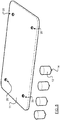
- the kit may comprise a support surface 11 that is provided with a plurality of retainers 20 that are configured to align with the through-holes 19 so that appropriate connectors attached to the legs may be pushed through the through-holes 19 to mate and couple with the retainers.
- the retainers could comprise captive nuts
- the connectors may comprise bolts fittable or pre-fitted to respective legs.
- eyelets may be fitted to the cover to reinforce the aforementioned through-holes 19.
- the respective parts of the cover that surround the through-holes may be reinforced, for example by means of stitching or by affixing a more resilient material to the cover in the vicinity of the through-holes 19.
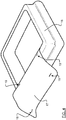
- a user need only insert the support surface into the bed (for example by releasing panel 17 and sliding the support surface into the void as shown in Fig. 6 ) so that it lies on top of the core and between the cover and the core.
- the user need only then reattach panel 17 to the remainder of the cover and affix the legs to the support surface (as shown in Fig. 7 ) through the cover to provide a raised bed.
- kits also allows any given bed that provides access to the core to be converted into a raised bed. This means that animals can still use beds with which they have become familiar and do not have to get used to a new bed.
- the through-holes 19 are provided in the panel 17 of the cover 15, this is not an essential feature of the present invention.
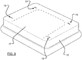
- the through-holes 19 may be provided in a region of the cover adjacent to the panel 17.
- some through-holes may be provided in the panel 17 and others in the cover 15.
Landscapes
- Life Sciences & Earth Sciences (AREA)
- Environmental Sciences (AREA)
- Animal Behavior & Ethology (AREA)
- Zoology (AREA)
- Animal Husbandry (AREA)
- Biodiversity & Conservation Biology (AREA)
- Housing For Livestock And Birds (AREA)
- Invalid Beds And Related Equipment (AREA)
Abstract
Description
- This invention relates to improvements to animal beds, particularly but not exclusively to dog beds. One illustrative aspect of the invention relates to a kit for converting an animal bed into a raised animal bed. Another illustrative aspect of the invention relates to a cover for an animal bed, and a further aspect of the invention relates to an animal bed.
- Arrangements embodying the teachings of the invention will be described hereafter with reference to beds for dogs, but this should not be construed as being a limitation of the scope of the invention, as such beds could conceivably be used by a variety of different animals.
- Animal beds, such as a dog bed for example, typically comprise a core and a removable cover for the core. A conventional floor-lying bed that is available from Omlet Ltd, Tuthill Park, Wardington, Oxfordshire OX17 1RR, United Kingdom is depicted in
Fig. 1 . This dog bed comprises a padded core and a removable outer cover that includes a peripheral bolster. The cover can be taken off the core for cleaning in a washing machine. - Whilst this illustrative dog bed provides a comfortable bed for a dog, it is the case that some dogs (and indeed their owners) prefer their beds to be elevated from the floor so that the bed is less likely to move around when the dog climbs on and off the bed.
- To this end it has previously been proposed to provide items of furniture which essentially comprise a supporting frame, mounted on legs, for an animal bed of the type described above. One illustrative example is the "Raised Wooden Dog Bed" available from Charley Chau Limited, Unit 16, Astra Road, Astra Business Park, Guinness Road, Manchester M17 1SU, United Kingdom. This solid wood product, whilst being fit for purpose, is expensive to ship to customers, large and cumbersome to move around, non-portable, cannot readily be disassembled and is expensive.
- It has also previously been proposed to provide more elaborate "pet sofas", for example the Antoinette Pet Sofa available from Lord Lou, Cruquiuszoom 37, 2142 EW Cruquius, The Netherlands; which again whilst being fit for purpose is expensive (in terms of shipping and purchase), non-portable and cannot be disassembled (which can be a particular problem if the fabric of the sofa (as opposed to the cushion) should be dirtied by the animal).
- Another drawback associated with previously proposed floor-lying and raised animal beds is that one cannot readily be converted into the other.
- Aspects of the present invention has been devised with the foregoing in mind.
- In accordance with a presently preferred embodiment of the present invention, there is provided a kit for converting a floor-lying animal bed comprising a core and a cover into a raised animal bed, the kit comprising: a support surface insertable into the animal bed so as to lie between the core and a part of the cover that forms the underside of the bed in use; a plurality of legs, and fixings for coupling the legs to the support surface through said part of the cover. By virtue of this arrangement, floor-lying animal beds can readily and quickly be converted into raised beds.
- In one embodiment, the fixings may comprise screws. The screws may comprise double-ended screws. The support may include a plurality of retainers configured to cooperate with said fixings to couple said legs to the support. The retainers may comprise a plurality of captive nuts embedded in said support. The fixings may comprise bolts that can be coupled to said captive nuts.
- Preferably the cover has a plurality of through-holes provided in the part of the cover that forms the underside of the bed in use. This arrangement reduces the likelihood of the cover being damaged.
- Preferably, each said through-hole is configured to align with a respective retainer in said support when said support has been inserted into the animal bed so as to lie between the core and the part of the cover that forms the underside of the bed in use. The cover may be reinforced in the vicinity of said through holes. The reinforcement may be provided by means of a plurality of eyelets.
- The core may comprise a padded body, a foam body or a bean bag.
- Another aspect of the present invention relates to a cover for an animal bed, said cover being configured and arranged for use with the kit described herein.
- A further aspect of the invention comprises a raised animal bed comprising a kit as described herein.
- In another implementation of the teachings of the invention, there is provided a cover for an animal bed, the cover comprising a plurality of surfaces that cooperate to define an internal void for receiving an animal bed core, said cover being openable to enable access to be had to said void, the cover further comprising a plurality of through-holes provided in one said surface that forms the underside of the animal bed in use.
- Preferably the cover is reinforced in the vicinity of said through holes. The reinforcement may be provided by means of a plurality of eyelets, each said eyelet being associated with a respective one of said through-holes.
- Another implementation of the teachings of the invention provides a raised animal bed comprising a cover and a core, wherein said cover comprises a plurality of panels that cooperate to define an internal void, the cover being openable to permit the core to be inserted into said void, a panel of said cover that forms the underside of said animal bed in use including a plurality of through-holes; the bed further comprising a support surface locatable within said void between the core and the panel of the cover that forms the underside of the bed so that respective ones of a plurality of retainers provided in said support surface are aligned with respective through-holes in said cover, and a plurality of legs each having a leg fixing associated therewith, each leg fixing being insertable through a respective through-hole and into engagement with a respective retainer in said support surface to couple the legs to said support surface through the cover.
- Preferably the retainers comprise captive nuts embedded in said support surface and said fixings comprise bolts engageable with said nuts.
- Other features, advantages and embodiments of the invention are set out elsewhere in the present application.
- Various aspects of the teachings of the present invention, and arrangements embodying those teachings, will hereafter be described by way of illustrative example with reference to the accompanying drawings, in which:
-
Fig. 1 is a photograph of a conventional floor-lying dog bed; -
Fig. 2 is a schematic representation of the underside of a conventional animal bed; -
Fig. 3 is a schematic representation of a kit that embodies the teachings of the present invention; -
Fig. 4 is a schematic representation of a cover for an animal bed; -
Fig. 5 is a schematic representation of another kit that embodies the teachings of the present invention; -
Figs. 6 and 7 are schematic representations of the steps in a conversion process; -
Fig. 8 is a schematic perspective view of an animal bed in which a kit embodying the teachings of the invention has been installed to provide a raised animal bed; and -
Fig. 9 is a schematic representation of another cover for an animal bed. - Referring now to
Fig. 2 , there is depicted a schematic representation of the underside of an illustrative conventional animal bed 1, in this instance a dog bed. In this example, the bed 1 has a generally rectangular footprint, but it will be appreciated that the shape of the bed may be varied as desired. - The bed 1 comprises an
outer cover 5, preferably of a fabric material, that defines an internal void within which aninner core 3 is enclosed. Typically, the core is compressible, but it needn't necessarily be so. The cover, as will be appreciated, protects the core from damage and helps keep the core clean. In this instance apanel 7 forming the underside of the bed 1 is detachable (at least in part) from the remainder of the cover so that the core can be removed, and the cover can be cleaned. To that end, it is preferred for the cover to be machine-washable. - Whilst it is preferred for the
panel 7 to be provided on the underside of the bed 1, it will be appreciated that this is not essential and the panel could comprise a sidewall, or indeed the top wall, of the bed. Similarly, whilst it is preferred for the cover and core to be separable to enable the cover to be cleaned, it is only necessary for the core to be accessible in order to implement the teachings of the present invention. - The
panel 7 is preferably coupled to the remainder of the cover by means of a zip fastener that extends, in this arrangement around three sides of the panel. In alternative arrangements thepanel 7 could be secured to the remainder of the cover by another type of fastener, for example buttons, press studs, a two-part mechanical hook and loop mechanism (such as Velcro™) or by any of a variety of alternatives the like of which will be immediately apparent to persons of skill in the art. - The
inner core 3 comprises, in this example, a rectangular cuboid foam structure configured to fit within thecover 5. It will be appreciated, however, that a variety of different types of core could instead be provided. For example, the core could comprise a padded body (akin to a pillow), memory foam, a bean bag or a variety of other alternatives the like of which will be immediately apparent to persons of skill in the art. In preferred arrangements the core is of a hypoallergenic material that may also include an appropriate biocide and/or stain resistant compound. - Referring now to
Fig. 3 of the drawings, there is depicted akit 9 that embodies a first aspect of the present invention. Thekit 9 is configured for converting the bed 1 ofFig. 2 into a raised bed and comprises a planar support surface 11 (for example of wood, plastics or other stiff material) that can be inserted into the bed 1 so that thesupport surface 11 lies between thecore 3 and theouter cover 5, in one envisaged arrangement between thecore 3 and thepanel 7 of the cover that forms the underside of the bed 1. The kit further comprises a plurality oflegs 13 and fixings 14 (shown coupled to the legs 13) enabling the legs to be connected to the support surface through the outer cover to raise the bed. In this instance four identical legs are provided, but it will be appreciated that a fewer or great number of legs may be provided and that they needn't be identical. - The fixings could comprise any of a number of different types of fixing. For example, in one envisaged arrangement they could each comprise a double-ended screw - one end being screwable into a given leg and the other end being screwable into the support surface through the cover.
- It is also envisaged that the legs could be moulded around a part of the fixing, leaving the remainder of the fixing extending from the leg so that it can be connected (for example screwed) into the support surface.
- To use the kit, a user need only insert the support surface into the bed (for example by releasing
panel 7 and sliding the support surface into the void) so that it lies on top of the core and between the cover and the core. The user need only then reattachpanel 7 to the remainder of the cover and affix the legs to the support surface through the cover to provide a raised bed. Advantageously, since the animal bed cores are generally compressible, the kit can be used with many (if not all) different types of animal bed. - Whilst this implementation of the teachings of the invention does allow the bed to be raised, it is recognised that repeated disconnection and reattachment of the legs from the support surface may result in undue wear to the underside of the cover. To that end, in accordance with another aspect of the present invention, there is provided a
cover 15 for an animal bed as shown inFig. 4 of the drawings. - In this embodiment, the
cover 15 includes a panel 17 (that forms the underside of the bed in use) that is provided with a plurality of through-holes 19. The through-holes are sized to allow a said fixing to be screwed through the through-holes 19 and into the support surface without causing damage to the cover. This arrangement is advantageous in that it allows the bed to be disassembled (for example for cleaning of the cover) and reassembled without affecting the integrity of the cover. - In one particularly preferred embodiment depicted in
Fig. 5 , the kit may comprise asupport surface 11 that is provided with a plurality ofretainers 20 that are configured to align with the through-holes 19 so that appropriate connectors attached to the legs may be pushed through the through-holes 19 to mate and couple with the retainers. For example, the retainers could comprise captive nuts, and the connectors may comprise bolts fittable or pre-fitted to respective legs. - In an envisaged implementation eyelets may be fitted to the cover to reinforce the aforementioned through-
holes 19. Alternatively, the respective parts of the cover that surround the through-holes may be reinforced, for example by means of stitching or by affixing a more resilient material to the cover in the vicinity of the through-holes 19. - As before, to use the kit a user need only insert the support surface into the bed (for example by releasing
panel 17 and sliding the support surface into the void as shown inFig. 6 ) so that it lies on top of the core and between the cover and the core. The user need only then reattachpanel 17 to the remainder of the cover and affix the legs to the support surface (as shown inFig. 7 ) through the cover to provide a raised bed. - It will be apparent from the foregoing that aspects of the present invention readily enable the conversion of a conventional animal bed into a raised
animal bed 21 such as that which is depicted inFig. 8 , in some cases without affecting the integrity of the cover of the bed. Transport of the bed can be facilitated as compared with a ready-made raised bed, and users can switch between raised and floor-lying beds as they wish. Advantageously, the kit also allows any given bed that provides access to the core to be converted into a raised bed. This means that animals can still use beds with which they have become familiar and do not have to get used to a new bed. - It will be appreciated that whilst various aspects and embodiments of the present invention have heretofore been described, the scope of the present invention is not limited to the particular arrangements set out herein and instead extends to encompass all arrangements, and modifications and alterations thereto, which fall within the scope of the appended claims.
- For example, whilst in
Fig. 4 the through-holes 19 are provided in thepanel 17 of thecover 15, this is not an essential feature of the present invention. In another envisaged implementation shown schematically inFig. 9 , the through-holes 19 may be provided in a region of the cover adjacent to thepanel 17. In yet another envisaged implementation that is not depicted in the drawings, some through-holes may be provided in thepanel 17 and others in thecover 15. - It should also be noted that whilst the accompanying claims set out particular combinations of features described herein, the scope of the present invention is not limited to the particular combinations hereafter claimed, but instead extends to encompass any combination of features herein disclosed.
- Finally, it should be noted that any element in a claim that does not explicitly state "means for" performing a specified function, or "steps for" performing a specific function, is not to be interpreted as a "means" or "step" clause as specified in 35 U.S.C. Sec. 112, par. 6. In particular, the use of "step of in the claims appended hereto is not intended to invoke the provisions of 35 U.S.C. Sec. 112, par. 6.
Claims (18)
- A kit for converting an animal bed comprising a core and a cover into a raised animal bed, the kit comprising: a support surface insertable into the animal bed so as to lie between the core and a part of the cover that forms the underside of the bed in use; a plurality of legs, and fixings for coupling the legs to the support surface through said part of the cover.
- A kit according to Claim 1, wherein said fixings comprise screws.
- A kit according to Claim 2, wherein said screws comprise double-ended screws.
- A kit according to Claim 1, wherein said support includes a plurality of retainers configured to cooperate with said fixings to couple said legs to the support.
- A kit according to Claim 4, wherein said retainers comprise a plurality of captive nuts embedded in said support.
- A kit according to Claim 5, wherein said fixings comprise bolts that can be coupled to said captive nuts.
- A kit according to any preceding claim, wherein said cover has a plurality of through-holes provided in the part of the cover that forms the underside of the bed in use.
- A kit according to Claim 7 when dependent on any of Claims 5 or 6 wherein each said through-hole is configured to align with a respective retainer in said support when said support has been inserted into the animal bed so as to lie between the core and the part of the cover that forms the underside of the bed in use.
- A kit according to Claim 7 or 8, wherein the cover is reinforced in the vicinity of said through holes.
- A kit according to Claim 9, wherein said reinforcement is provided by means of a plurality of eyelets.
- A kit according to any preceding claim, wherein said core is selected from: a padded body, a foam body or a bean bag.
- A cover for an animal bed, said cover being configured and arranged for use with the kit of any preceding claim.
- A raised animal bed comprising a kit according to any of claims 1 to 11.
- A cover for an animal bed, the cover comprising a plurality of surfaces that cooperate to define an internal void for receiving an animal bed core, said cover being openable to enable access to be had to said void, the cover further comprising a plurality of through-holes provided in one said surface that forms the underside of the animal bed in use.
- A cover according to Claim 14, wherein the cover is reinforced in the vicinity of said through holes.
- A cover according to Claim 15, wherein said reinforcement is provided by means of a plurality of eyelets, each said eyelet being associated with a respective one of said through-holes.
- A raised animal bed comprising a cover and a core, wherein said cover comprises a plurality of panels that cooperate to define an internal void, the cover being openable to permit the core to be inserted into said void, a panel of said cover that forms the underside of said animal bed in use including a plurality of through-holes;
the bed further comprising a support surface locatable within said void between the core and the panel of the cover that forms the underside of the bed so that respective ones of a plurality of retainers provided in said support surface are aligned with respective through-holes in said cover, and
a plurality of legs each having a leg fixing associated therewith, each leg fixing being insertable through a respective through-hole and into engagement with a respective retainer in said support surface to couple the legs to said support surface through the cover. - A raised animal bed according to Claim 17, wherein said retainers comprise captive nuts embedded in said support surface and said fixings comprise bolts engageable with said nuts.
Applications Claiming Priority (2)
| Application Number | Priority Date | Filing Date | Title |
|---|---|---|---|
| GB1907184.4A GB2584114A (en) | 2019-05-21 | 2019-05-21 | Improvements relating to animal beds |
| GB1911615.1A GB2585954A (en) | 2019-05-21 | 2019-08-14 | Improvements relating to animal beds |
Publications (4)
| Publication Number | Publication Date |
|---|---|
| EP3815521A2 true EP3815521A2 (en) | 2021-05-05 |
| EP3815521A3 EP3815521A3 (en) | 2021-07-28 |
| EP3815521C0 EP3815521C0 (en) | 2025-01-08 |
| EP3815521B1 EP3815521B1 (en) | 2025-01-08 |
Family
ID=67385324
Family Applications (1)
| Application Number | Title | Priority Date | Filing Date |
|---|---|---|---|
| EP20175925.5A Active EP3815521B1 (en) | 2019-05-21 | 2020-05-21 | Improvements relating to animal beds |
Country Status (3)
| Country | Link |
|---|---|
| US (2) | US11419307B2 (en) |
| EP (1) | EP3815521B1 (en) |
| GB (2) | GB2584114A (en) |
Families Citing this family (11)
| Publication number | Priority date | Publication date | Assignee | Title |
|---|---|---|---|---|
| GB2601192B (en) * | 2020-11-24 | 2023-11-15 | Hebe Studio Ltd | Animal Bed |
| USD1006338S1 (en) * | 2021-04-28 | 2023-11-28 | Hebe Studio Limited | Mattress of an animal bed assembly |
| USD1001388S1 (en) * | 2021-04-28 | 2023-10-10 | Hebe Studio Limited | Bean bag top member of an animal bed assembly |
| USD1000720S1 (en) * | 2021-04-28 | 2023-10-03 | Hebe Studio Limited | Bolster member of an animal bed assembly |
| USD1001386S1 (en) * | 2021-04-28 | 2023-10-10 | Hebe Studio Limited | Bean bag top member of an animal bed assembly |
| USD1027319S1 (en) * | 2022-05-22 | 2024-05-14 | Wen Xu | Elliptical dog bed |
| US12029196B1 (en) * | 2023-02-22 | 2024-07-09 | Plusmofa International Ltd. | Pet couch |
| USD1007772S1 (en) * | 2023-05-30 | 2023-12-12 | Pengfei Ren | Pet bed |
| USD1020115S1 (en) * | 2023-11-24 | 2024-03-26 | Xiangfa Zhu | Pet bed |
| USD1045242S1 (en) * | 2024-04-22 | 2024-10-01 | Shanghai Oceania International Co., Ltd. | Pet sofa |
| USD1057307S1 (en) * | 2024-08-02 | 2025-01-07 | Xiaofeng Dong | Pet bed |
Family Cites Families (14)
| Publication number | Priority date | Publication date | Assignee | Title |
|---|---|---|---|---|
| US441527A (en) * | 1890-11-25 | Meat-block | ||
| US2212485A (en) * | 1937-08-14 | 1940-08-20 | Sure Fit Products Company | Slip cover construction for upholstered furniture |
| US4169428A (en) * | 1977-10-07 | 1979-10-02 | Waugh Dorothy C | Pet sleeping bag |
| GB8714961D0 (en) * | 1987-06-25 | 1987-07-29 | Spite G W | Bed for pets |
| AUPO337296A0 (en) | 1996-11-01 | 1996-11-28 | ALDERMAN, John Patterson | Portable collapsible dog or pet bed |
| GB0107980D0 (en) * | 2001-03-30 | 2001-05-23 | Eurostitch Ltd | Pet beds |
| US7614362B2 (en) * | 2005-06-01 | 2009-11-10 | Munchkin, Inc. | Modular pet bed assembly |
| US7806080B2 (en) * | 2006-12-04 | 2010-10-05 | Christopher Brooks Morse | Zipper system for removable covers on pet furniture |
| AU2011100225A4 (en) * | 2011-02-27 | 2011-03-31 | Peters, Graham Mr | Combination dog bed |
| US20120318206A1 (en) * | 2011-06-15 | 2012-12-20 | Van Leeuwen Matthys | Elevated Pet Furniture |
| US8370973B1 (en) * | 2011-09-19 | 2013-02-12 | Zinus, Inc. | Collapsible, folding mattress support having the appearance of a box spring with legs |
| US10314286B2 (en) * | 2015-11-15 | 2019-06-11 | Dee Volin | Shape-shifting self-draining indoor-outdoor exercise pet tree, having rotatable slanting logs, rotatable slanting steps, rotatable slanting branches, rotatable slanting houses, rotatable slanting accessories, and rotatable slanting wheels |
| US10905093B2 (en) * | 2017-06-26 | 2021-02-02 | Ivars R. Repins | Pet bed |
| CN208807317U (en) * | 2018-01-16 | 2019-05-03 | 上海恺羿网络科技有限公司 | A kind of Pet bed |
-
2019
- 2019-05-21 GB GB1907184.4A patent/GB2584114A/en not_active Withdrawn
- 2019-08-14 GB GB1911615.1A patent/GB2585954A/en not_active Withdrawn
-
2020
- 2020-05-21 US US16/879,995 patent/US11419307B2/en active Active
- 2020-05-21 EP EP20175925.5A patent/EP3815521B1/en active Active
-
2022
- 2022-06-22 US US17/846,454 patent/US11985952B2/en active Active
Also Published As
| Publication number | Publication date |
|---|---|
| US11985952B2 (en) | 2024-05-21 |
| US20200367467A1 (en) | 2020-11-26 |
| EP3815521A3 (en) | 2021-07-28 |
| US11419307B2 (en) | 2022-08-23 |
| EP3815521C0 (en) | 2025-01-08 |
| GB201907184D0 (en) | 2019-07-03 |
| US20220312724A1 (en) | 2022-10-06 |
| EP3815521B1 (en) | 2025-01-08 |
| GB2584114A (en) | 2020-11-25 |
| GB201911615D0 (en) | 2019-09-25 |
| GB2585954A (en) | 2021-01-27 |
Similar Documents
| Publication | Publication Date | Title |
|---|---|---|
| US11985952B2 (en) | Animal beds | |
| KR101073748B1 (en) | modular furniture assembly | |
| US6964246B2 (en) | Pet step and method | |
| US12178188B2 (en) | Animal bed | |
| US8037649B2 (en) | Portable steps | |
| US20010013145A1 (en) | Portable cot apparatus | |
| US20050051106A1 (en) | Modular pet furniture | |
| KR20060012426A (en) | Pet bathing device and bathing method using the device | |
| WO2022112259A1 (en) | Animal bed | |
| KR101843349B1 (en) | House for pet | |
| WO2019051531A1 (en) | Furniture item and method of assembling same | |
| JP2003159156A (en) | Bed equipment | |
| GB2206272A (en) | Pet bed | |
| KR20110088576A (en) | Modular furniture assemblies | |
| HK1120378B (en) | Modular furniture assembly | |
| HK1159447B (en) | Modular furniture assembly | |
| HK1120709B (en) | Modular furniture assembly | |
| JPH04317605A (en) | Unit table |
Legal Events
| Date | Code | Title | Description |
|---|---|---|---|
| STAA | Information on the status of an ep patent application or granted ep patent |
Free format text: STATUS: UNKNOWN |
|
| PUAI | Public reference made under article 153(3) epc to a published international application that has entered the european phase |
Free format text: ORIGINAL CODE: 0009012 |
|
| STAA | Information on the status of an ep patent application or granted ep patent |
Free format text: STATUS: THE APPLICATION HAS BEEN PUBLISHED |
|
| AK | Designated contracting states |
Kind code of ref document: A2 Designated state(s): AL AT BE BG CH CY CZ DE DK EE ES FI FR GB GR HR HU IE IS IT LI LT LU LV MC MK MT NL NO PL PT RO RS SE SI SK SM TR |
|
| PUAL | Search report despatched |
Free format text: ORIGINAL CODE: 0009013 |
|
| AK | Designated contracting states |
Kind code of ref document: A3 Designated state(s): AL AT BE BG CH CY CZ DE DK EE ES FI FR GB GR HR HU IE IS IT LI LT LU LV MC MK MT NL NO PL PT RO RS SE SI SK SM TR |
|
| RIC1 | Information provided on ipc code assigned before grant |
Ipc: A01K 1/035 20060101AFI20210621BHEP |
|
| RAP3 | Party data changed (applicant data changed or rights of an application transferred) |
Owner name: HEBE STUDIO LIMITED |
|
| STAA | Information on the status of an ep patent application or granted ep patent |
Free format text: STATUS: REQUEST FOR EXAMINATION WAS MADE |
|
| 17P | Request for examination filed |
Effective date: 20220112 |
|
| RBV | Designated contracting states (corrected) |
Designated state(s): AL AT BE BG CH CY CZ DE DK EE ES FI FR GB GR HR HU IE IS IT LI LT LU LV MC MK MT NL NO PL PT RO RS SE SI SK SM TR |
|
| RIN1 | Information on inventor provided before grant (corrected) |
Inventor name: WINDHAM, WILLIAM Inventor name: PAUL, JOHANNES Inventor name: NICHOLLS, SIMON Inventor name: TUTHILL, JAMES |
|
| GRAP | Despatch of communication of intention to grant a patent |
Free format text: ORIGINAL CODE: EPIDOSNIGR1 |
|
| STAA | Information on the status of an ep patent application or granted ep patent |
Free format text: STATUS: GRANT OF PATENT IS INTENDED |
|
| RIC1 | Information provided on ipc code assigned before grant |
Ipc: A01K 1/035 20060101AFI20240724BHEP |
|
| INTG | Intention to grant announced |
Effective date: 20240807 |
|
| GRAS | Grant fee paid |
Free format text: ORIGINAL CODE: EPIDOSNIGR3 |
|
| GRAA | (expected) grant |
Free format text: ORIGINAL CODE: 0009210 |
|
| STAA | Information on the status of an ep patent application or granted ep patent |
Free format text: STATUS: THE PATENT HAS BEEN GRANTED |
|
| AK | Designated contracting states |
Kind code of ref document: B1 Designated state(s): AL AT BE BG CH CY CZ DE DK EE ES FI FR GB GR HR HU IE IS IT LI LT LU LV MC MK MT NL NO PL PT RO RS SE SI SK SM TR |
|
| REG | Reference to a national code |
Ref country code: GB Ref legal event code: FG4D |
|
| REG | Reference to a national code |
Ref country code: CH Ref legal event code: EP |
|
| REG | Reference to a national code |
Ref country code: DE Ref legal event code: R096 Ref document number: 602020044407 Country of ref document: DE |
|
| REG | Reference to a national code |
Ref country code: IE Ref legal event code: FG4D |
|
| U01 | Request for unitary effect filed |
Effective date: 20250109 |
|
| U07 | Unitary effect registered |
Designated state(s): AT BE BG DE DK EE FI FR IT LT LU LV MT NL PT RO SE SI Effective date: 20250117 |
|
| PG25 | Lapsed in a contracting state [announced via postgrant information from national office to epo] |
Ref country code: RS Free format text: LAPSE BECAUSE OF FAILURE TO SUBMIT A TRANSLATION OF THE DESCRIPTION OR TO PAY THE FEE WITHIN THE PRESCRIBED TIME-LIMIT Effective date: 20250408 |
|
| PG25 | Lapsed in a contracting state [announced via postgrant information from national office to epo] |
Ref country code: PL Free format text: LAPSE BECAUSE OF FAILURE TO SUBMIT A TRANSLATION OF THE DESCRIPTION OR TO PAY THE FEE WITHIN THE PRESCRIBED TIME-LIMIT Effective date: 20250108 |
|
| U20 | Renewal fee for the european patent with unitary effect paid |
Year of fee payment: 6 Effective date: 20250530 |
|
| PG25 | Lapsed in a contracting state [announced via postgrant information from national office to epo] |
Ref country code: ES Free format text: LAPSE BECAUSE OF FAILURE TO SUBMIT A TRANSLATION OF THE DESCRIPTION OR TO PAY THE FEE WITHIN THE PRESCRIBED TIME-LIMIT Effective date: 20250108 |
|
| PG25 | Lapsed in a contracting state [announced via postgrant information from national office to epo] |
Ref country code: IS Free format text: LAPSE BECAUSE OF FAILURE TO SUBMIT A TRANSLATION OF THE DESCRIPTION OR TO PAY THE FEE WITHIN THE PRESCRIBED TIME-LIMIT Effective date: 20250508 Ref country code: NO Free format text: LAPSE BECAUSE OF FAILURE TO SUBMIT A TRANSLATION OF THE DESCRIPTION OR TO PAY THE FEE WITHIN THE PRESCRIBED TIME-LIMIT Effective date: 20250408 |
|
| PG25 | Lapsed in a contracting state [announced via postgrant information from national office to epo] |
Ref country code: HR Free format text: LAPSE BECAUSE OF FAILURE TO SUBMIT A TRANSLATION OF THE DESCRIPTION OR TO PAY THE FEE WITHIN THE PRESCRIBED TIME-LIMIT Effective date: 20250108 |
|
| PG25 | Lapsed in a contracting state [announced via postgrant information from national office to epo] |
Ref country code: GR Free format text: LAPSE BECAUSE OF FAILURE TO SUBMIT A TRANSLATION OF THE DESCRIPTION OR TO PAY THE FEE WITHIN THE PRESCRIBED TIME-LIMIT Effective date: 20250409 |
|
| PG25 | Lapsed in a contracting state [announced via postgrant information from national office to epo] |
Ref country code: SM Free format text: LAPSE BECAUSE OF FAILURE TO SUBMIT A TRANSLATION OF THE DESCRIPTION OR TO PAY THE FEE WITHIN THE PRESCRIBED TIME-LIMIT Effective date: 20250108 |
|
| PG25 | Lapsed in a contracting state [announced via postgrant information from national office to epo] |
Ref country code: CZ Free format text: LAPSE BECAUSE OF FAILURE TO SUBMIT A TRANSLATION OF THE DESCRIPTION OR TO PAY THE FEE WITHIN THE PRESCRIBED TIME-LIMIT Effective date: 20250108 |
|
| PG25 | Lapsed in a contracting state [announced via postgrant information from national office to epo] |
Ref country code: SK Free format text: LAPSE BECAUSE OF FAILURE TO SUBMIT A TRANSLATION OF THE DESCRIPTION OR TO PAY THE FEE WITHIN THE PRESCRIBED TIME-LIMIT Effective date: 20250108 |
|
| PLBE | No opposition filed within time limit |
Free format text: ORIGINAL CODE: 0009261 |
|
| STAA | Information on the status of an ep patent application or granted ep patent |
Free format text: STATUS: NO OPPOSITION FILED WITHIN TIME LIMIT |
|
| REG | Reference to a national code |
Ref country code: CH Ref legal event code: L10 Free format text: ST27 STATUS EVENT CODE: U-0-0-L10-L00 (AS PROVIDED BY THE NATIONAL OFFICE) Effective date: 20251119 |
|
| 26N | No opposition filed |
Effective date: 20251009 |
|
| REG | Reference to a national code |
Ref country code: CH Ref legal event code: H13 Free format text: ST27 STATUS EVENT CODE: U-0-0-H10-H13 (AS PROVIDED BY THE NATIONAL OFFICE) Effective date: 20251223 |
|
| PG25 | Lapsed in a contracting state [announced via postgrant information from national office to epo] |
Ref country code: CH Free format text: LAPSE BECAUSE OF NON-PAYMENT OF DUE FEES Effective date: 20250531 |
|
| PG25 | Lapsed in a contracting state [announced via postgrant information from national office to epo] |
Ref country code: MC Free format text: LAPSE BECAUSE OF FAILURE TO SUBMIT A TRANSLATION OF THE DESCRIPTION OR TO PAY THE FEE WITHIN THE PRESCRIBED TIME-LIMIT Effective date: 20250108 |
|
| U20 | Renewal fee for the european patent with unitary effect paid |
Year of fee payment: 7 Effective date: 20260530 |
|
| PGFP | Annual fee paid to national office [announced via postgrant information from national office to epo] |
Ref country code: GB Payment date: 20260530 Year of fee payment: 7 |
|
| PGFP | Annual fee paid to national office [announced via postgrant information from national office to epo] |
Ref country code: IE Payment date: 20260530 Year of fee payment: 7 |
|
| PG25 | Lapsed in a contracting state [announced via postgrant information from national office to epo] |
Ref country code: CY Free format text: LAPSE BECAUSE OF FAILURE TO SUBMIT A TRANSLATION OF THE DESCRIPTION OR TO PAY THE FEE WITHIN THE PRESCRIBED TIME-LIMIT Effective date: 20250108 |