EP3815409B1 - User equipment capability indication for cell identification - Google Patents
User equipment capability indication for cell identification Download PDFInfo
- Publication number
- EP3815409B1 EP3815409B1 EP19846268.1A EP19846268A EP3815409B1 EP 3815409 B1 EP3815409 B1 EP 3815409B1 EP 19846268 A EP19846268 A EP 19846268A EP 3815409 B1 EP3815409 B1 EP 3815409B1
- Authority
- EP
- European Patent Office
- Prior art keywords
- information
- beam sweeping
- ssb
- measurement
- time period
- Prior art date
- Legal status (The legal status is an assumption and is not a legal conclusion. Google has not performed a legal analysis and makes no representation as to the accuracy of the status listed.)
- Active
Links
Images


Classifications
-
- H—ELECTRICITY
- H04—ELECTRIC COMMUNICATION TECHNIQUE
- H04W—WIRELESS COMMUNICATION NETWORKS
- H04W24/00—Supervisory, monitoring or testing arrangements
- H04W24/02—Arrangements for optimising operational condition
-
- H—ELECTRICITY
- H04—ELECTRIC COMMUNICATION TECHNIQUE
- H04W—WIRELESS COMMUNICATION NETWORKS
- H04W16/00—Network planning, e.g. coverage or traffic planning tools; Network deployment, e.g. resource partitioning or cells structures
- H04W16/24—Cell structures
- H04W16/28—Cell structures using beam steering
-
- H—ELECTRICITY
- H04—ELECTRIC COMMUNICATION TECHNIQUE
- H04B—TRANSMISSION
- H04B7/00—Radio transmission systems, i.e. using radiation field
- H04B7/02—Diversity systems; Multi-antenna system, i.e. transmission or reception using multiple antennas
- H04B7/04—Diversity systems; Multi-antenna system, i.e. transmission or reception using multiple antennas using two or more spaced independent antennas
- H04B7/0404—Diversity systems; Multi-antenna system, i.e. transmission or reception using multiple antennas using two or more spaced independent antennas the mobile station comprising multiple antennas, e.g. to provide uplink diversity
-
- H—ELECTRICITY
- H04—ELECTRIC COMMUNICATION TECHNIQUE
- H04B—TRANSMISSION
- H04B7/00—Radio transmission systems, i.e. using radiation field
- H04B7/02—Diversity systems; Multi-antenna system, i.e. transmission or reception using multiple antennas
- H04B7/04—Diversity systems; Multi-antenna system, i.e. transmission or reception using multiple antennas using two or more spaced independent antennas
- H04B7/06—Diversity systems; Multi-antenna system, i.e. transmission or reception using multiple antennas using two or more spaced independent antennas at the transmitting station
- H04B7/0613—Diversity systems; Multi-antenna system, i.e. transmission or reception using multiple antennas using two or more spaced independent antennas at the transmitting station using simultaneous transmission
- H04B7/0615—Diversity systems; Multi-antenna system, i.e. transmission or reception using multiple antennas using two or more spaced independent antennas at the transmitting station using simultaneous transmission of weighted versions of same signal
- H04B7/0617—Diversity systems; Multi-antenna system, i.e. transmission or reception using multiple antennas using two or more spaced independent antennas at the transmitting station using simultaneous transmission of weighted versions of same signal for beam forming
-
- H—ELECTRICITY
- H04—ELECTRIC COMMUNICATION TECHNIQUE
- H04B—TRANSMISSION
- H04B7/00—Radio transmission systems, i.e. using radiation field
- H04B7/02—Diversity systems; Multi-antenna system, i.e. transmission or reception using multiple antennas
- H04B7/04—Diversity systems; Multi-antenna system, i.e. transmission or reception using multiple antennas using two or more spaced independent antennas
- H04B7/06—Diversity systems; Multi-antenna system, i.e. transmission or reception using multiple antennas using two or more spaced independent antennas at the transmitting station
- H04B7/0613—Diversity systems; Multi-antenna system, i.e. transmission or reception using multiple antennas using two or more spaced independent antennas at the transmitting station using simultaneous transmission
- H04B7/0615—Diversity systems; Multi-antenna system, i.e. transmission or reception using multiple antennas using two or more spaced independent antennas at the transmitting station using simultaneous transmission of weighted versions of same signal
- H04B7/0619—Diversity systems; Multi-antenna system, i.e. transmission or reception using multiple antennas using two or more spaced independent antennas at the transmitting station using simultaneous transmission of weighted versions of same signal using feedback from receiving side
- H04B7/0621—Feedback content
- H04B7/0626—Channel coefficients, e.g. channel state information [CSI]
-
- H—ELECTRICITY
- H04—ELECTRIC COMMUNICATION TECHNIQUE
- H04B—TRANSMISSION
- H04B7/00—Radio transmission systems, i.e. using radiation field
- H04B7/02—Diversity systems; Multi-antenna system, i.e. transmission or reception using multiple antennas
- H04B7/04—Diversity systems; Multi-antenna system, i.e. transmission or reception using multiple antennas using two or more spaced independent antennas
- H04B7/08—Diversity systems; Multi-antenna system, i.e. transmission or reception using multiple antennas using two or more spaced independent antennas at the receiving station
- H04B7/0868—Hybrid systems, i.e. switching and combining
- H04B7/088—Hybrid systems, i.e. switching and combining using beam selection
-
- H—ELECTRICITY
- H04—ELECTRIC COMMUNICATION TECHNIQUE
- H04W—WIRELESS COMMUNICATION NETWORKS
- H04W48/00—Access restriction; Network selection; Access point selection
- H04W48/16—Discovering, processing access restriction or access information
-
- H—ELECTRICITY
- H04—ELECTRIC COMMUNICATION TECHNIQUE
- H04W—WIRELESS COMMUNICATION NETWORKS
- H04W56/00—Synchronisation arrangements
- H04W56/001—Synchronization between nodes
-
- H—ELECTRICITY
- H04—ELECTRIC COMMUNICATION TECHNIQUE
- H04W—WIRELESS COMMUNICATION NETWORKS
- H04W76/00—Connection management
- H04W76/10—Connection setup
- H04W76/11—Allocation or use of connection identifiers
-
- H—ELECTRICITY
- H04—ELECTRIC COMMUNICATION TECHNIQUE
- H04W—WIRELESS COMMUNICATION NETWORKS
- H04W8/00—Network data management
- H04W8/22—Processing or transfer of terminal data, e.g. status or physical capabilities
- H04W8/24—Transfer of terminal data
Definitions
- Various embodiments generally may relate to the field of wireless communications.
- the intra-frequency cell identification delay requirements measurements correspond to T PSS/SSS_sync (time period used in Primary Synchronization Signal (PSS) or Secondary Synchronization Signal (SSS detection), T SSB_time_index (time period used to acquire the index of the SSB being measured), T SSB_measurement_period (measurement period of SSB based measurement) as defined in the Third Generation Partnership Project's (3GPP's) Technical Specification 38.133.
- the intra-frequency cell identification delay requirements measurements depend among other things on the configuration of each particular user equipment (UE).
- the number of receive (Rx) beams used by any given user equipment (UE) is implementation-specific.
- To have a single number for the Rx beams to define beamforming requirements to allow intra-frequency cell identification delay requirements measurements is limiting, as different UE types could have different numbers of antenna elements and different number of Rx beams.
- WO 2017/118898 A1 discloses methods for adaptively configuring a measurement period in a user equipment or another network node.
- the measurement period can be determined based at least in part on an assessment of one or more conditions, wherein each of the measurement periods is associated with at least one condition.
- the determined measurement period can be used for performing and/or reporting one or more measurements.
- 3rd Generation Partnership Project Technical Specification Group Radio Access Network
- NR Technical Specification Group Radio Access Network
- 3GPP TS 38.133 V15.2.0 specifies requirements for support of Radio Resource Management for FDD and TDD modes of New Radio (NR). These requirements include requirements on measurements in NR and the UE as well as requirements on node dynamical behavior and interaction, in terms of delay and response characteristics.
- the intra-frequency cell identification delay requirements measurements are comprised of TPSS/SSS_sync (time period used in Primary Synchronization Signal (PSS) or Secondary Synchronization Signal (SSS detection), TSSB_time_index (time period used to acquire the index of the SSB being measured), T SSB_measurement_period (measurement period of SSB based measurement).
- Intra-frequency cells may include neighbor cells on the same frequency as the serving cell, but with a different primary scrambling code.
- the intra-frequency cell info list sent in SIB11 may include up to 8 cells, indexed from 0 to 7.
- SIB11 refers to the system information block type 11 in NR which contains measurement control information to be used in a cell.
- frequency range in which 5G NR operates are categories into following two designations: (1) FR1 corresponding to a frequency range from 450 to 6000 MHz; and (2) FR2 corresponding to a frequency range is from 24250 to 52600 MHz.
- SSB refers to "Secondary Synchronization Block”
- RRM refers to "Radio Resource Management”
- SS refers to “Synchronization Signal”
- Rx refers to "Receive”
- SMTC refers to "SS/PBCH Block Measurement Time Configuration,” where PBCH refers to "Physical Broadcast Channel.”
- the intra-frequency cell identification delay requirements were defined in the Third Generation Partnership Project (3GPP) Technical Specification (TS) 38.133 version 15.2.0 (TS 38.133 v15.2.0) as follows:
- the time period for detection and measurement may be defined in certain instances based on a generic formula corresponding to FR1 without measurement gaps by a maximum value as between a lower bound value, and a value based on a number of samples times a SS/PBCH Block Measurement Time Configuration (SMTC_period), where "PBCH” stands for "Physical Broadcast Channel.”
- the T PSS/SSS_sync , T SSB_measurement_period , and T SSB_time_index values may be based on: max lower _ bound , number _ of _ samples ⁇ SMTC _ period
- the lower bound and number of samples are based on a tradeoff between the mobility of the UE in question, that is, the UE mobility and power consumption by the UE, which tradeoff may be found through simulation and numerical analysis for the required cell acquisition or measurement.
- the time period for detection and measurement that is, the T PSS/SSS_sync , T SSB_measurement_period , and T SSB_time_index values may be defined in certain instances based on a generic formula corresponding to FR2 without measurement gaps by a maximum value as between a lower bound value, and scale factor times a value based on a number of samples times a SMTC_period.
- T PSS/SSS_sync , T SSB_measurement_period , and T SSB_time_index values may be based on: max lower _ bound , N ⁇ number _ of _ samples ⁇ SMTC _ period where N is a scale factor to account for Rx beam sweeping.
- a FR2 UE will utilize the analog and/or digital receiver beamforming for the measurement. Hence, longer measurement time is needed for FR2 to allow for the FR2 UE to sweep the whole space.
- An FR2 UE is required to decode PBCH payload during intra-frequency measurement and thus the longer time is needed for intra-frequency measurement. Hence, the measurement requirements are specified for FR1 and FR2 separately.
- the gNodeB with which the UE is to communicate, or more network elements of a core network within a network that includes the cells, may determine values for T PSS/SSS_sync , T SSB_measurement_period , and T SSB_time_index in order for the network to have knowledge regarding intra-frequency cell identification delays for UEs within the network.
- the number of samples and the scale factor N in Equation 1 depends on the UE.
- to have a single scale factor to allow intra-frequency cell identification delay requirements measurements would be limiting, as different UE types could have different numbers of antenna elements and different number of Rx beams.
- N may impact mobility requirements (if the UE moves, the given larger N may no longer be applicable), whereas having a small value for N to account for RX beam sweeping would fail to accommodate all types of UEs, which may provide larger beam sweeping capabilities than for example their mobile counterparts.
- a process 100 may include, at operation 102, generating a signal including capability information of the UE, wherein a time period for intra-frequency cell detection and measurement for the UE is based on the capability information.
- Process 100 further includes, at operation 104, causing a transmission of the signal within a cellular network to include the UE using a radio frequency (RF) interface of the UE.
- RF radio frequency
- a UE may be configured to indicate at operation 202A, its capability, such as signaling delay for Rx beam forming.
- the gNodeB (or potentially the core network) is to adjust the timers and delay requirements in the context of intra-frequency cell identification delay requirements measurements based on the capability indication by the UE.
- network element may describe a physical or virtualized equipment used to provide wired or wireless communication network services.
- network element may be considered synonymous to and/or referred to as a networked computer, networking hardware, network equipment, router, switch, hub, bridge, radio network controller, radio access network device, gateway, server, VNF, NFVI, and/or the like.
- a UE may be configured to indicate its "type,” in terms of whether the type is "stationary,” “low mobility,” or "high mobility.”
- the UE may indicate, at operation 202B, its mobility type as its capability, that is, whether it is "stationary,” has “low mobility,” or “high mobility.” Whether a device's mobility can be characterized as “stationary,” “low” or “high” may be predefined for the UE and/or based on UE application needs.
- a stationary or low mobility UE could have a large number of beams and take longer time for cell identification without impacting mobility performance, whereas a high mobility UE could take shorter time for Rx beam sweeping and cell identification.
- the delay requirements would be set at operation 204B by a gNode B or core network according to the mobility type declared by the UE, and the gNodeB or core network could also set the SMTC periodicity for the cells to be measured based on the UE mobility. For example, gNodeB or core network could set a lower periodicity for high mobility UEs, and higher periodicity for low mobility or stationary UEs.
- the UE may at operation 202C indicate its capability in terms of the number of beams required for SSB- based measurements, such as cell identification, radio link monitoring, and beam failure detection.
- the gNodeB or core network may set the requirements for the SSB-based measurements delay based on the indicated capability, and may further set the SMTC periodicity based on the number of beam required for the SSB-based measurements.
- the UE may signal the number of beams it uses for Rx beam sweeping for cell identification purposes. This number could be used as the scale factor N in the requirements noted above.
- a UE capability indication for the maximum number of Rx beams used for CSI-RS, maxNumberRxBeam, at the Radio Frequency (RF) layer may, according to one embodiment, be used for the latter purpose.
- a UE is configured to indicate its capability in terms of time needed for cell identification. For example, the UE may indicate its capability in terms of whether the time needed for cell identification is "long,” “medium,” or "short.”
- NR New Radio
- gNodeB New Radio evolved Node B
- the number of Rx beams and the delay requirements could be different as between the UEs.
- gNodeB or core network could use this capability to determine or adjust delay requirement for a given UE.
- PSS/SSS detection, SSB index acquisition and measurement in FR2 are defined as the following in TS 38.133 v.15.2.0: Table 9.2.5.1-2: Time period for PSS/SSS detection, (Frequency range FR2) DRX cycle T PSS/SSS_sync No DRX max[ 600ms, ceil( [5] x K p ) x N 1 x SMTC period ] Note 1 DRX cycle ⁇ 320ms max[ 600ms, ceil(1.5 x [5] x K p ) x N 1 x max(SMTC period,DRX cycle) ] DRX cycle>320ms Ceil( [5] x K p ) x N 1 x DRX cycle ...
- SMTC period in the requirement is the one used by the cell being identified Table 9.2.5.1-4: Time period for time index detection (Frequency range FR2) DRX cycle T SSB_time_index No DRX max[ 200ms, ceil( [5] x K p ) x N 2 x SMTC period ] Note 1 DRX cycle ⁇ 320ms max[ 200ms, ceil (1.5 x[5] x K p ) x N 2 x max(SMTC period,DRX cycle) ] DRX cycle>320ms Ceil( [5] x K p ) x N 2 x DRX cycle ... ...
- DRX refers to Discontinuous Reception, and is a technique that allows the mobile station to power down significant amounts of its internal circuitry for a high percentage of the time when it is in the idle mode. The period of time when the mobile station will be powered down is commonly called the "Sleep mode"
- K p 1/(1-(SMTC period /MGRP)), where SMTC period ⁇ MGRP.
- MGRP refers to Measurement Gap Repetition Period.
- the UE In FR2 in order to detect multiple intra-frequency cells, the UE needs to perform Rx beam sweeping.
- the number of Rx beams used by the UE depends on a number of factors, including: (1) the UE type, for example, whether the UE is a handheld UE or a vs Customer Premise Equipment (CPE) UE; handheld UEs have more mobility than CPE UEs, and typically a larger number of antenna elements; (2) the number of antenna panels and antenna elements per panel for a given UE; and (3) other implementation-based features of the UE.
- CPE Customer Premise Equipment
- UE capability signaling may be defined in order for network elements of the core network or a gNodeB (or gNB) to determine the time and delay requirements based on the UE capability signaling.
- the UE capability signaling may be implemented according to various embodiments and the delay requirements modified accordingly on gNodeB or core network side.
- Some embodiments may utilize one or both of two sets of requirements for UE requiring small delay vs long delay for Rx beam sweeping.
- the UE capability signaling shall declare short vs long delay for Rx beam sweeping and cell identification.
- the UE capability signaling would be based on the UE implementation and the requirements would be appropriate for the same.
- a time period for detection and measurement that is, the T PSS/SSS_sync , T SSB_measurement_period , and T SSB_time_index values may be defined in certain instances based on a generic formula by a maximum value as between a lower bound value, and scale factor times a value based on a number of samples times a SMTC_period, where the scale factor has one value, N short , when the UE has indicated that its beam sweeping delay is short, and another value, N long , when the UE has indicated that its beam sweeping delay is long.
- Whether a beam sweeping delay is "short” or “long” may be defined predefined for the UE and/or based on UE application needs.
- One or more of the T PSS/SSS_sync , T SSB_measurement_period , and T SSB_time_index values may therefore be based on: max lower _ bound , Nshort ⁇ number _ of _ samples ⁇ SMTC _ period max lower _ bound , Nlong ⁇ number _ of _ samples ⁇ SMTC _ period
- N short is a scale factor to account for Rx beam sweeping corresponding to a UE with a short beam sweeping delay
- N long is a scale factor to account for Rx beam sweeping corresponding to a UE with a long beam sweeping delay
- Some embodiments may include a combination of two or more of the embodiments noted herein.
- a gNodeB or core network may determine delay requirements and associated timers for each UE accordingly.
- Fig. 4 illustrates an architecture of a system 400 of a network according to some embodiments.
- the system 400 is shown to include a user equipment (UE) 401 and a UE 402.
- the UEs 401 and 402 are illustrated as smartphones (e.g., handheld touchscreen mobile computing devices connectable to one or more cellular networks), but may also comprise any mobile or non-mobile computing device.
- the UEs 401 and 402 may be configured to connect, e.g., communicatively couple, with a radio access network (RAN) 410.
- the UEs 401 and 402 utilize connections 403 and 404, respectively, each of which comprises a physical communications interface or layer (discussed in further detail below); in this example, the connections 403 and 404 are illustrated as an air interface to enable communicative coupling, and can be consistent with cellular communications protocols.
- the UEs 401 and 402 may further directly exchange communication data via a ProSe interface 405.
- the ProSe interface 405 may alternatively be referred to as a sidelink interface comprising one or more logical channels, including but not limited to a Physical Sidelink Control Channel (PSCCH), a Physical Sidelink Shared Channel (PSSCH), a Physical Sidelink Discovery Channel (PSDCH), and a Physical Sidelink Broadcast Channel (PSBCH).
- PSCCH Physical Sidelink Control Channel
- PSSCH Physical Sidelink Shared Channel
- PSDCH Physical Sidelink Discovery Channel
- PSBCH Physical Sidelink Broadcast Channel
- the UE 402 is shown to be configured to access an access point (AP) 406 via connection 407.
- the connection 407 can comprise a local wireless connection, such as a connection consistent with any IEEE 802.11 protocol, wherein the AP 406 would comprise a wireless fidelity (WiFi ® ) router.
- WiFi ® wireless fidelity
- the AP 406 is shown to be connected to the Internet without connecting to the core network of the wireless system (described in further detail below).
- the RAN 410 can include one or more access nodes that enable the connections 403 and 404.
- These access nodes can be referred to as base stations (BSs), NodeBs, evolved NodeBs (eNBs), next Generation NodeBs (gNB), RAN nodes, and so forth, and can comprise ground stations (e.g., terrestrial access points) or satellite stations providing coverage within a geographic area (e.g., a cell).
- BSs base stations
- eNBs evolved NodeBs
- gNB next Generation NodeBs
- RAN nodes and so forth, and can comprise ground stations (e.g., terrestrial access points) or satellite stations providing coverage within a geographic area (e.g., a cell).
- the RAN 410 may include one or more RAN nodes for providing macrocells, e.g., macro RAN node 411, and one or more RAN nodes for providing femtocells or picocells (e.g., cells having smaller coverage areas, smaller user capacity, or higher bandwidth compared to macrocells), e.g., low power (LP) RAN node 412.
- macro RAN node 411 e.g., macro RAN node 411
- femtocells or picocells e.g., cells having smaller coverage areas, smaller user capacity, or higher bandwidth compared to macrocells
- LP low power
- the UEs 401 and 402 can be configured to communicate using Orthogonal Frequency-Division Multiplexing (OFDM) communication signals with each other or with any of the RAN nodes 411 and 412 over a multicarrier communication channel in accordance various communication techniques, such as, but not limited to, an Orthogonal Frequency-Division Multiple Access (OFDMA) communication technique (e.g., for downlink communications) or a Single Carrier Frequency Division Multiple Access (SC-FDMA) communication technique (e.g., for uplink and ProSe or sidelink communications), although the scope of the embodiments is not limited in this respect.
- OFDM signals can comprise a plurality of orthogonal subcarriers.
- the RAN 410 is shown to be communicatively coupled to a core network (CN) 420 - via an S1 interface 413.
- the CN 420 may be an evolved packet core (EPC) network, a NextGen Packet Core (NPC) network, or some other type of CN.
- EPC evolved packet core
- NPC NextGen Packet Core
- the S1 interface 413 is split into two parts: the S1-U interface 414, which carries traffic data between the RAN nodes 411 and 412 and the serving gateway (S-GW) 422, and the S1-mobility management entity (MME) interface 415, which is a signaling interface between the RAN nodes 411 and 412 and MMEs 421.
- S-GW serving gateway
- MME S1-mobility management entity
- the CN 420 includes network elements.
- the term "network element” may describe a physical or virtualized equipment used to provide wired or wireless communication network services.
- the CN 420 comprises, as network elements, the MMEs 421, the S-GW 422, the Packet Data Network (PDN) Gateway (P-GW) 423, and a home subscriber server (HSS) 424.
- the MMEs 421 may be similar in function to the control plane of legacy Serving General Packet Radio Service (GPRS) Support Nodes (SGSN).
- GPRS General Packet Radio Service
- Fig. 5 illustrates example interfaces of baseband circuitry according to various embodiments.
- the baseband circuitry 500 may comprise processors 538-542 and a memory 544 utilized by said processors.
- Each of the processors 538-532 may include a memory interface, 504A-504E, respectively, to send/receive data to/from the memory 544.
- Baseband circuitry 500 may also include an audio digital signal processor (Audio DSP) 543.
- Audio DSP audio digital signal processor
- the baseband circuitry 500 may further include one or more interfaces to communicatively couple to other circuitries/devices, such as a memory interface 512 (e.g., an interface to send/receive data to/from memory external to the baseband circuitry 500), an application circuitry interface 514 (e.g., an interface to send/receive data to/from an application circuitry), an RF circuitry interface 516 (e.g., an interface to send/receive data to/from an RF circuitry), a wireless hardware connectivity interface 518 (e.g., an interface to send/receive data to/from Near Field Communication (NFC) components, Bluetooth ® components (e.g., Bluetooth ® Low Energy), Wi-Fi ® components, and other communication components), and a power management interface 520 (e.g., an interface to send/receive power or control signals to/from a power management integrated circuit (PMIC).
- a memory interface 512 e.g., an interface to send/receive data to/
- Fig. 6 is a block diagram illustrating components, according to some example embodiments, able to read instructions from a machine-readable or computer-readable medium (e.g., a non-transitory machine-readable storage medium) and perform any one or more of the methodologies discussed herein.
- Fig. 6 shows a diagrammatic representation of hardware resources 600 including one or more processors (or processor cores) 610, one or more memory/storage devices 620, and one or more communication resources 630, each of which may be communicatively coupled via a bus 640.
- node virtualization e.g., NFV
- a hypervisor 602 may be executed to provide an execution environment for one or more network slices/sub-slices to utilize the hardware resources 600
- the processors 610 may include, for example, a processor 612 and a processor 614.
- CPU central processing unit
- RISC reduced instruction set computing
- CISC complex instruction set computing
- GPU graphics processing unit
- DSP digital signal processor
- ASIC application specific integrated circuit
- RFIC radio-frequency integrated circuit
- the memory/storage devices 620 may include main memory, disk storage, or any suitable combination thereof.
- the memory/storage devices 620 may include, but are not limited to any type of volatile or non-volatile memory such as dynamic random access memory (DRAM), static random-access memory (SRAM), erasable programmable read-only memory (EPROM), electrically erasable programmable read-only memory (EEPROM), Flash memory, solid-state storage, etc.
- DRAM dynamic random access memory
- SRAM static random-access memory
- EPROM erasable programmable read-only memory
- EEPROM electrically erasable programmable read-only memory
- Flash memory solid-state storage, etc.
- the communication resources 630 may include interconnection or network interface components or other suitable devices to communicate with one or more peripheral devices 604 or one or more databases 606 via a network 608.
- the communication resources 630 may include wired communication components (e.g., for coupling via a Universal Serial Bus (USB)), cellular communication components, NFC components, Bluetooth ® components (e.g., Bluetooth ® Low Energy), Wi-Fi ® components, and other communication components.
- wired communication components e.g., for coupling via a Universal Serial Bus (USB)
- cellular communication components e.g., for coupling via a Universal Serial Bus (USB)
- NFC components e.g., NFC components
- Bluetooth ® components e.g., Bluetooth ® Low Energy
- Wi-Fi ® components e.g., Wi-Fi ® components
- Instructions 650 may comprise software, a program, an application, an applet, an app, or other executable code for causing at least any of the processors 610 to perform any one or more of the methodologies discussed herein.
- the instructions 650 may reside, completely or partially, within at least one of the processors 610 (e.g., within the processor's cache memory), the memory/storage devices 620, or any suitable combination thereof.
- any portion of the instructions 650 may be transferred to the hardware resources 600 from any combination of the peripheral devices 604 or the databases 606. Accordingly, the memory of processors 610, the memory/storage devices 620, the peripheral devices 604, and the databases 606 are examples of computer-readable and machine-readable media.
- the electronic device(s), network(s), system(s), chip(s) or component(s), or portions or implementations thereof, of figures 4-6 , or some other figure herein may be configured to perform one or more processes, techniques, or methods as described herein, or portions thereof. Embodiments of such processes are depicted in figs. 1- 3 .
- a process according to an embodiments may include indicating, or causing to be indicated, capability to the network about its rx beam sweeping delay requirement.
- smte refers to an ssb-based measurement timing configuration configured by ssb-measurementtimingconfiguration
- ssb refers to an ss/pbch block
- field may refer to individual contents of an information element
- information element refers to a structural element containing a single or multiple fields
- a "primary cell” refers to the mcg cell, operating on the primary frequency, in which the ue either performs the initial connection establishment procedure or initiates the connection re establishment procedure
- a "primary scg cell” refers to the scg cell in which the ue performs random access when performing the reconfiguration with sync procedure for dc operation
- a “secondary cell” refers to a cell providing additional radio resources on top of a special cell for a ue configured with ca
- a “secondary cell group” refers to the subset of serving cells comprising the pscell and zero or more secondary cells for a ue configured with d
Landscapes
- Engineering & Computer Science (AREA)
- Computer Networks & Wireless Communication (AREA)
- Signal Processing (AREA)
- Databases & Information Systems (AREA)
- Computer Security & Cryptography (AREA)
- Mobile Radio Communication Systems (AREA)
Description
- Various embodiments generally may relate to the field of wireless communications.
- In 5G/NR the intra-frequency cell identification delay requirements measurements correspond to TPSS/SSS_sync (time period used in Primary Synchronization Signal (PSS) or Secondary Synchronization Signal (SSS detection), TSSB_time_index (time period used to acquire the index of the SSB being measured), TSSB_measurement_period (measurement period of SSB based measurement) as defined in the Third Generation Partnership Project's (3GPP's) Technical Specification 38.133. The intra-frequency cell identification delay requirements measurements depend among other things on the configuration of each particular user equipment (UE).
- For example, the number of receive (Rx) beams used by any given user equipment (UE) is implementation-specific. To have a single number for the Rx beams to define beamforming requirements to allow intra-frequency cell identification delay requirements measurements is limiting, as different UE types could have different numbers of antenna elements and different number of Rx beams.
- Mechanisms are needed to allow intra-frequency cell identification delay requirements measurements given their dependency on UE configurations.
WO 2017/118898 A1 discloses methods for adaptively configuring a measurement period in a user equipment or another network node. The measurement period can be determined based at least in part on an assessment of one or more conditions, wherein each of the measurement periods is associated with at least one condition. The determined measurement period can be used for performing and/or reporting one or more measurements.
LG Electronics: "Discussion on RRM core requirements with Rx beamforming in FR2", 3GPP TSG-RAN WG4 Meeting #87, R4-186838 discloses RRM core requirements for UE Rx beamforming in FR2.
3rd Generation Partnership Project; Technical Specification Group Radio Access Network; NR; Requirements for support of radio resource management (Release 15), 3GPP TS 38.133 V15.2.0 specifies requirements for support of Radio Resource Management for FDD and TDD modes of New Radio (NR). These requirements include requirements on measurements in NR and the UE as well as requirements on node dynamical behavior and interaction, in terms of delay and response characteristics. -
-
Fig. 1 illustrates a process to be performed at a New Radio (NR) User Equipment (UE) according to some embodiments; -
Figs. 2A-2C illustrate respective processes to be performed at a NR UE according to respective embodiments; -
Fig. 3 illustrates a process to be performed at a NR evolved Node B (gNodeB) according to some embodiments; -
Fig. 4 illustrates an architecture of asystem 400 of a network according to some embodiments -
Fig. 5 illustrates example interfaces of baseband circuitry according to various embodiments; and -
Fig. 6 is a block diagram illustrating components, according to some example embodiments, able to read instructions from a machine-readable or computer-readable medium. - The invention is defined by the features of the independent claims. Preferred advantageous embodiments thereof are defined by the sub-features of the dependent claims.
- The following detailed description refers to the accompanying drawings. The same reference numbers may be used in different drawings to identify the same or similar elements. In the following description, for purposes of explanation and not limitation, specific details are set forth such as particular structures, architectures, interfaces, techniques, etc. in order to provide a thorough understanding of the various aspects of various embodiments. However, it will be apparent to those skilled in the art having the benefit of the present disclosure that the various aspects of the various embodiments may be practiced in other examples that depart from these specific details. In certain instances, descriptions of well-known devices, circuits, and methods are omitted so as not to obscure the description of the various embodiments with unnecessary detail. For the purposes of the present document, the phrase "A or B" means (A), (B), or (A and B).
- In 5G/NR the intra-frequency cell identification delay requirements measurements are comprised of TPSS/SSS_sync (time period used in Primary Synchronization Signal (PSS) or Secondary Synchronization Signal (SSS detection), TSSB_time_index (time period used to acquire the index of the SSB being measured), T SSB_measurement_period (measurement period of SSB based measurement). Intra-frequency cells may include neighbor cells on the same frequency as the serving cell, but with a different primary scrambling code. The intra-frequency cell info list sent in SIB11 may include up to 8 cells, indexed from 0 to 7. SIB11 refers to the system information block type 11 in NR which contains measurement control information to be used in a cell.
- It is noted that frequency range in which 5G NR operates are categories into following two designations: (1) FR1 corresponding to a frequency range from 450 to 6000 MHz; and
(2) FR2 corresponding to a frequency range is from 24250 to 52600 MHz. In addition, "SSB" as used herein refers to "Secondary Synchronization Block," "RRM" refers to "Radio Resource Management," "SS" refers to "Synchronization Signal," "Rx" refers to "Receive," and "SMTC" refers to "SS/PBCH Block Measurement Time Configuration," where PBCH refers to "Physical Broadcast Channel." - The intra-frequency cell identification delay requirements were defined in the Third Generation Partnership Project (3GPP) Technical Specification (TS) 38.133 version 15.2.0 (TS 38.133 v15.2.0) as follows:
- "The UE shall be able to identify a new detectable intra frequency cell within Tidentify_intra_without_index if UE is not indicated to report SSB based RRM measurement result with the associated SSB index, or the UE has been indicated that the neighbour cell is synchronous with the serving cell. Otherwise UE shall be able to identify a new detectable intra frequency cell within Tidentify_incra_with_index. The UE shall be able to identify a new detectable intra frequency SS block of an already detected cell within Tidentify_intra_without_index.


- Where:
- TPSS/SSS_sync: it is the time period used in PSS/SSS detection given in table 9.2.5.1-1, 9.2.5.1-2, 9.2.5.1-5 (deactivated Scell) or 9.2.5.1-6 (deactivated SCell)
- TSSB_time_index: it is the time period used to acquire the index of the SSB being measured given in table 9.2.5.1-3 or 9.2.5.1-4 or 9.2.5.1-7 (deactivated SCell) or 9.2.5.1-8 (deactivated SCell)
- TSSB_measurement_period: equal to a measurement period of SSB based measurement given in table 9.2.5.2-1, table 9.2.5.2-2 table 9.2.5.2-3 (deactivated Scell) or 9.2.5.2-4(deactivated SCell)."
- In the above equations, Kca is defined or FR1, as Kca =1 for measurements on frequencies corresponding to PCell or PSCell, and Kca is defined as Kca =number of configured SCells for measurements on frequencies corresponding to FR1 only SCells.
- The time period for detection and measurement, that is, the TPSS/SSS_sync, TSSB_measurement_period, and TSSB_time_index values may be defined in certain instances based on a generic formula corresponding to FR1 without measurement gaps by a maximum value as between a lower bound value, and a value based on a number of samples times a SS/PBCH Block Measurement Time Configuration (SMTC_period), where "PBCH" stands for "Physical Broadcast Channel." The TPSS/SSS_sync, TSSB_measurement_period, and TSSB_time_index values may be based on:

- The lower bound and number of samples are based on a tradeoff between the mobility of the UE in question, that is, the UE mobility and power consumption by the UE, which tradeoff may be found through simulation and numerical analysis for the required cell acquisition or measurement.
- In FR2 the UE needs to perform Rx beam sweeping in order to identify the cell. The time period for detection and measurement, that is, the TPSS/SSS_sync, TSSB_measurement_period, and TSSB_time_index values may be defined in certain instances based on a generic formula corresponding to FR2 without measurement gaps by a maximum value as between a lower bound value, and scale factor times a value based on a number of samples times a SMTC_period. One or more of the TPSS/SSS_sync, TSSB_measurement_period, and TSSB_time_index values may be based on:

- From measurement perspective, a FR2 UE will utilize the analog and/or digital receiver beamforming for the measurement. Hence, longer measurement time is needed for FR2 to allow for the FR2 UE to sweep the whole space. An FR2 UE is required to decode PBCH payload during intra-frequency measurement and thus the longer time is needed for intra-frequency measurement. Hence, the measurement requirements are specified for FR1 and FR2 separately.
- The gNodeB with which the UE is to communicate, or more network elements of a core network within a network that includes the cells, may determine values for TPSS/SSS_sync, TSSB_measurement_period, and TSSB_time_index in order for the network to have knowledge regarding intra-frequency cell identification delays for UEs within the network. However, by way of example, the number of samples and the scale factor N in
Equation 1 depends on the UE. Again, by way of example, to have a single scale factor to allow intra-frequency cell identification delay requirements measurements would be limiting, as different UE types could have different numbers of antenna elements and different number of Rx beams. In addition, having a large value for N could impact mobility requirements (if the UE moves, the given larger N may no longer be applicable), whereas having a small value for N to account for RX beam sweeping would fail to accommodate all types of UEs, which may provide larger beam sweeping capabilities than for example their mobile counterparts. - According to the invention, as shown by way of example in
Fig. 1 , aprocess 100 may include, atoperation 102, generating a signal including capability information of the UE, wherein a time period for intra-frequency cell detection and measurement for the UE is based on the capability information.Process 100 further includes, atoperation 104, causing a transmission of the signal within a cellular network to include the UE using a radio frequency (RF) interface of the UE. - Referring now to
Fig. 2A , according an embodiment as shown inprocess 200A, a UE may be configured to indicate atoperation 202A, its capability, such as signaling delay for Rx beam forming. Atoperation 204A, the gNodeB (or potentially the core network) is to adjust the timers and delay requirements in the context of intra-frequency cell identification delay requirements measurements based on the capability indication by the UE. - The term "network element" may describe a physical or virtualized equipment used to provide wired or wireless communication network services. The term "network element" may be considered synonymous to and/or referred to as a networked computer, networking hardware, network equipment, router, switch, hub, bridge, radio network controller, radio access network device, gateway, server, VNF, NFVI, and/or the like.
- According to yet another embodiment, a UE may be configured to indicate its "type," in terms of whether the type is "stationary," "low mobility," or "high mobility."
- According to an embodiment, as shown by way of example by the
process 200B inFig. 2B , the UE may indicate, atoperation 202B, its mobility type as its capability, that is, whether it is "stationary," has "low mobility," or "high mobility." Whether a device's mobility can be characterized as "stationary," "low" or "high" may be predefined for the UE and/or based on UE application needs. A stationary or low mobility UE could have a large number of beams and take longer time for cell identification without impacting mobility performance, whereas a high mobility UE could take shorter time for Rx beam sweeping and cell identification. The delay requirements would be set atoperation 204B by a gNode B or core network according to the mobility type declared by the UE, and the gNodeB or core network could also set the SMTC periodicity for the cells to be measured based on the UE mobility. For example, gNodeB or core network could set a lower periodicity for high mobility UEs, and higher periodicity for low mobility or stationary UEs. - According to one embodiment, as shown by
process 200C ofFig. 2C , the UE may atoperation 202C indicate its capability in terms of the number of beams required for SSB- based measurements, such as cell identification, radio link monitoring, and beam failure detection. Atoperation 204C, the gNodeB or core network may set the requirements for the SSB-based measurements delay based on the indicated capability, and may further set the SMTC periodicity based on the number of beam required for the SSB-based measurements. - According to one embodiment, the UE may signal the number of beams it uses for Rx beam sweeping for cell identification purposes. This number could be used as the scale factor N in the requirements noted above. A UE capability indication for the maximum number of Rx beams used for CSI-RS, maxNumberRxBeam, at the Radio Frequency (RF) layer may, according to one embodiment, be used for the latter purpose.
- According to the invention, a UE is configured to indicate its capability in terms of time needed for cell identification. For example, the UE may indicate its capability in terms of whether the time needed for cell identification is "long," "medium," or "short."
- Referring now to
Fig. 3 , aprocess 300 to be performed at a New Radio (NR) evolved Node B (gNodeB) incudes, atoperation 302, processing a signal including capability information of a UE of the NR network, and, atoperation 304, determining a time period for intra-frequency cell detection and measurement for the UE based on the capability information. - As noted above, because of differing UE implementations, including different UE types, UE power requirements, UE mobilities, etc., for example in the case of FR2, the number of Rx beams and the delay requirements could be different as between the UEs. According to some embodiments, when the UE can signal its capabilities, gNodeB or core network could use this capability to determine or adjust delay requirement for a given UE.
- The requirements for PSS/SSS detection, SSB index acquisition and measurement in FR2 are defined as the following in TS 38.133 v.15.2.0:
Table 9.2.5.1-2: Time period for PSS/SSS detection, (Frequency range FR2) DRX cycle TPSS/SSS_sync No DRX max[ 600ms, ceil( [5] x Kp) x N1 x SMTC period ] Note 1 DRX cycle≤ 320ms max[ 600ms, ceil(1.5 x [5] x Kp) x N1 x max(SMTC period,DRX cycle) ] DRX cycle>320ms Ceil( [5] x Kp) x N1 x DRX cycle ... ... NOTE 1: If different SMTC periodicities are configured for different cells, the SMTC period in the requirement is the one used by the cell being identified Table 9.2.5.1-4: Time period for time index detection (Frequency range FR2) DRX cycle TSSB_time_index No DRX max[ 200ms, ceil( [5] x Kp) x N2 x SMTC period ]Note 1 DRX cycle≤ 320ms max[ 200ms, ceil (1.5 x[5] x Kp) x N2 x max(SMTC period,DRX cycle) ] DRX cycle>320ms Ceil( [5] x Kp) x N2 x DRX cycle ... ... NOTE 1: If different SMTC periodicities are configured for different cells, the SMTC period in the requirement is the one used by the cell being identified Table 9.2.5.2-2: Measurement period for intra-frequency measurements without gaps(Frequency FR2) DRX cycle T SSB_measurement_period No DRX max[ 400ms, ceil( 5 x Kp) x N3 x SMTC period ] Note 1 DRX cycle≤ 320ms max[ 400ms, ceil(1.5x 5 x Kp) x N3 x max(SMTC period,DRX cycle) ] DRX cycle>320ms ceil(5 xKp ) x N3 x DRX cycle NOTE 1: If different SMTC periodicities are configured for different cells, the SMTC period in the requirement is the one used by the cell being identified - "DRX" refers to Discontinuous Reception, and is a technique that allows the mobile station to power down significant amounts of its internal circuitry for a high percentage of the time when it is in the idle mode. The period of time when the mobile station will be powered down is commonly called the "Sleep mode"
- When intra-frequency SMTC is fully non overlapping with measurement gaps, Kp=1
- When intra-frequency is partially overlapping with measurement gaps, Kp = 1/(1-(SMTC period /MGRP)), where SMTC period < MGRP. "MGRP" refers to Measurement Gap Repetition Period.
- In FR2 in order to detect multiple intra-frequency cells, the UE needs to perform Rx beam sweeping. The number of Rx beams used by the UE depends on a number of factors, including: (1) the UE type, for example, whether the UE is a handheld UE or a vs Customer Premise Equipment (CPE) UE; handheld UEs have more mobility than CPE UEs, and typically a larger number of antenna elements; (2) the number of antenna panels and antenna elements per panel for a given UE; and (3) other implementation-based features of the UE.
- In some embodiments, UE capability signaling may be defined in order for network elements of the core network or a gNodeB (or gNB) to determine the time and delay requirements based on the UE capability signaling.
- The UE capability signaling may be implemented according to various embodiments and the delay requirements modified accordingly on gNodeB or core network side.
- Some embodiments may utilize one or both of two sets of requirements for UE requiring small delay vs long delay for Rx beam sweeping. With this the UE capability signaling shall declare short vs long delay for Rx beam sweeping and cell identification. The UE capability signaling would be based on the UE implementation and the requirements would be appropriate for the same.
- According to one embodiment, a time period for detection and measurement, that is, the TPSS/SSS_sync, TSSB_measurement_period, and TSSB_time_index values may be defined in certain instances based on a generic formula by a maximum value as between a lower bound value, and scale factor times a value based on a number of samples times a SMTC_period, where the scale factor has one value, Nshort, when the UE has indicated that its beam sweeping delay is short, and another value, Nlong, when the UE has indicated that its beam sweeping delay is long. Whether a beam sweeping delay is "short" or "long" may be defined predefined for the UE and/or based on UE application needs. One or more of the TPSS/SSS_sync, TSSB_measurement_period, and TSSB_time_index values may therefore be based on:


- where Nshort is a scale factor to account for Rx beam sweeping corresponding to a UE with a short beam sweeping delay, and Nlong is a scale factor to account for Rx beam sweeping corresponding to a UE with a long beam sweeping delay.
- Some embodiments may include a combination of two or more of the embodiments noted herein. Based on signaling from the UE as described above, a gNodeB or core network may determine delay requirements and associated timers for each UE accordingly.
-
Fig. 4 illustrates an architecture of asystem 400 of a network according to some embodiments. Thesystem 400 is shown to include a user equipment (UE) 401 and aUE 402. TheUEs - The
UEs UEs connections connections - In this embodiment, the
UEs ProSe interface 405. TheProSe interface 405 may alternatively be referred to as a sidelink interface comprising one or more logical channels, including but not limited to a Physical Sidelink Control Channel (PSCCH), a Physical Sidelink Shared Channel (PSSCH), a Physical Sidelink Discovery Channel (PSDCH), and a Physical Sidelink Broadcast Channel (PSBCH). - The
UE 402 is shown to be configured to access an access point (AP) 406 viaconnection 407. Theconnection 407 can comprise a local wireless connection, such as a connection consistent with any IEEE 802.11 protocol, wherein theAP 406 would comprise a wireless fidelity (WiFi®) router. In this example, theAP 406 is shown to be connected to the Internet without connecting to the core network of the wireless system (described in further detail below). - The
RAN 410 can include one or more access nodes that enable theconnections RAN 410 may include one or more RAN nodes for providing macrocells, e.g.,macro RAN node 411, and one or more RAN nodes for providing femtocells or picocells (e.g., cells having smaller coverage areas, smaller user capacity, or higher bandwidth compared to macrocells), e.g., low power (LP) RAN node 412. - According to some embodiments, the
UEs RAN nodes 411 and 412 over a multicarrier communication channel in accordance various communication techniques, such as, but not limited to, an Orthogonal Frequency-Division Multiple Access (OFDMA) communication technique (e.g., for downlink communications) or a Single Carrier Frequency Division Multiple Access (SC-FDMA) communication technique (e.g., for uplink and ProSe or sidelink communications), although the scope of the embodiments is not limited in this respect. The OFDM signals can comprise a plurality of orthogonal subcarriers. - The
RAN 410 is shown to be communicatively coupled to a core network (CN) 420 - via anS1 interface 413. In embodiments, theCN 420 may be an evolved packet core (EPC) network, a NextGen Packet Core (NPC) network, or some other type of CN. In this embodiment theS1 interface 413 is split into two parts: the S1-U interface 414, which carries traffic data between theRAN nodes 411 and 412 and the serving gateway (S-GW) 422, and the S1-mobility management entity (MME)interface 415, which is a signaling interface between theRAN nodes 411 and 412 andMMEs 421. - The
CN 420 includes network elements. The term "network element" may describe a physical or virtualized equipment used to provide wired or wireless communication network services. In this embodiment, theCN 420 comprises, as network elements, theMMEs 421, the S-GW 422, the Packet Data Network (PDN) Gateway (P-GW) 423, and a home subscriber server (HSS) 424. TheMMEs 421 may be similar in function to the control plane of legacy Serving General Packet Radio Service (GPRS) Support Nodes (SGSN). -
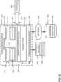
Fig. 5 illustrates example interfaces of baseband circuitry according to various embodiments. Thebaseband circuitry 500 may comprise processors 538-542 and amemory 544 utilized by said processors. Each of the processors 538-532 may include a memory interface, 504A-504E, respectively, to send/receive data to/from thememory 544.Baseband circuitry 500 may also include an audio digital signal processor (Audio DSP) 543. - The
baseband circuitry 500 may further include one or more interfaces to communicatively couple to other circuitries/devices, such as a memory interface 512 (e.g., an interface to send/receive data to/from memory external to the baseband circuitry 500), an application circuitry interface 514 (e.g., an interface to send/receive data to/from an application circuitry), an RF circuitry interface 516 (e.g., an interface to send/receive data to/from an RF circuitry), a wireless hardware connectivity interface 518 (e.g., an interface to send/receive data to/from Near Field Communication (NFC) components, Bluetooth® components (e.g., Bluetooth® Low Energy), Wi-Fi® components, and other communication components), and a power management interface 520 (e.g., an interface to send/receive power or control signals to/from a power management integrated circuit (PMIC). -
Fig. 6 is a block diagram illustrating components, according to some example embodiments, able to read instructions from a machine-readable or computer-readable medium (e.g., a non-transitory machine-readable storage medium) and perform any one or more of the methodologies discussed herein. Specifically,Fig. 6 shows a diagrammatic representation of hardware resources 600 including one or more processors (or processor cores) 610, one or more memory/storage devices 620, and one ormore communication resources 630, each of which may be communicatively coupled via abus 640. For embodiments where node virtualization (e.g., NFV) is utilized, ahypervisor 602 may be executed to provide an execution environment for one or more network slices/sub-slices to utilize the hardware resources 600 - The processors 610 (e.g., a central processing unit (CPU), a reduced instruction set computing (RISC) processor, a complex instruction set computing (CISC) processor, a graphics processing unit (GPU), a digital signal processor (DSP) such as a baseband processor, an application specific integrated circuit (ASIC), a radio-frequency integrated circuit (RFIC), another processor, or any suitable combination thereof) may include, for example, a
processor 612 and aprocessor 614. - The memory/
storage devices 620 may include main memory, disk storage, or any suitable combination thereof. The memory/storage devices 620 may include, but are not limited to any type of volatile or non-volatile memory such as dynamic random access memory (DRAM), static random-access memory (SRAM), erasable programmable read-only memory (EPROM), electrically erasable programmable read-only memory (EEPROM), Flash memory, solid-state storage, etc. - The
communication resources 630 may include interconnection or network interface components or other suitable devices to communicate with one or moreperipheral devices 604 or one or more databases 606 via anetwork 608. For example, thecommunication resources 630 may include wired communication components (e.g., for coupling via a Universal Serial Bus (USB)), cellular communication components, NFC components, Bluetooth® components (e.g., Bluetooth® Low Energy), Wi-Fi® components, and other communication components. -
Instructions 650 may comprise software, a program, an application, an applet, an app, or other executable code for causing at least any of theprocessors 610 to perform any one or more of the methodologies discussed herein. Theinstructions 650 may reside, completely or partially, within at least one of the processors 610 (e.g., within the processor's cache memory), the memory/storage devices 620, or any suitable combination thereof. Furthermore, any portion of theinstructions 650 may be transferred to the hardware resources 600 from any combination of theperipheral devices 604 or the databases 606. Accordingly, the memory ofprocessors 610, the memory/storage devices 620, theperipheral devices 604, and the databases 606 are examples of computer-readable and machine-readable media. - in some embodiments, the electronic device(s), network(s), system(s), chip(s) or component(s), or portions or implementations thereof, of
figures 4-6 , or some other figure herein, may be configured to perform one or more processes, techniques, or methods as described herein, or portions thereof. Embodiments of such processes are depicted infigs. 1- 3 . For example, a process according to an embodiments may include indicating, or causing to be indicated, capability to the network about its rx beam sweeping delay requirement. - in the present disclosure, "smte" refers to an ssb-based measurement timing configuration configured by ssb-measurementtimingconfiguration; "ssb" refers to an ss/pbch block; "field" may refer to individual contents of an information element; "information element" refers to a structural element containing a single or multiple fields; a "primary cell" refers to the mcg cell, operating on the primary frequency, in which the ue either performs the initial connection establishment procedure or initiates the connection re establishment procedure; a "primary scg cell" refers to the scg cell in which the ue performs random access when performing the reconfiguration with sync procedure for dc operation; a "secondary cell" refers to a cell providing additional radio resources on top of a special cell for a ue configured with ca; a "secondary cell group" refers to the subset of serving cells comprising the pscell and zero or more secondary cells for a ue configured with dc; a "serving cell" refers to the primary cell for a ue in rrc_connected not configured with ca/dc there is only one serving cell comprising of the primary cell; "serving cell" or "serving cells" refers to the set of cells comprising the special cell(s) and all secondary cells for a ue in rrc_connected configured with ca/dc; a "special cell" refers to the pcell of the mcg or the pscell of the scg for dc operation; otherwise, the term "special cell" refers to the pcell.
Claims (12)
- A New Radio, NR, User Equipment, UE (401, 402), comprising a Radio Frequency, RF, interface (516) and a baseband processor (538-542) coupled to the RF interface (516), wherein the baseband processor is configured (538-542) to:generate (102) a signal including capability information of the UE (401, 402), wherein a time period for intra-frequency cell detection and measurement for the UE (401, 402) is determined by a NR evolved Node B, gNodeB (411, 412), based on the capability information; andcause a transmission (104) of the signal including the capability information of the UE (401, 402) to the NR gNodeB (411, 412);wherein the capability information includes:information regarding an identification time period for intra-frequency cell identification by the UE (401, 402); andinformation on whether the identification time period for intra-frequency cell identification by the UE (401, 402) is long, medium or short.
- The NR UE of claim 1, wherein the time period includes at least one of TPSS/SSS_sync, TSSB_measurement_period, and TSSB_time_index.
- The NR UE of claim 1, wherein the capability information further includes at least one of:information regarding a capability of the UE (401, 402) for receive, Rx, beamforming;information on a number of beams required for Secondary Synchronization Block, SSB,-based measurements;mobility type information on a UE mobility type for the UE (401, 402);information on power requirements of the UE (401, 402); orreceive, Rx, beam sweeping information for the UE (401, 402).
- The NR UE of claim 3, wherein the Rx beam sweeping information includes information on at least one of: a number of beams the UE (401, 402) is to use for receive, Rx, beam sweeping for cell identification; or whether a delay for Rx beam sweeping for the UE corresponds to a long delay or a short delay.
- The NR UE of claim 4, wherein the number of beams the UE (401, 402) is to use for Rx beam sweeping corresponds to a maximum number of Rx beams the UE (401, 402) is to use for channel state information reference signal, CSI-RS, "maxNumberRxBeam".
- The NR UE of any one of claims 1-5, wherein:the UE (401, 402) is to operate in a 24.25 GHz to 52.6 GHz frequency range, a FR2 frequency range; andthe time period corresponds to a maximum value as between a lower bound value, and an upper value based on a scale factor, N, for receive, Rx, beam sweeping times a value based on a number of samples times a time period for a Secondary Signal/Physical Broadcast Channel Block measurement time configuration "SMTC_period".
- The NR UE of claim 6, wherein the scale factor corresponds to Nshort when a delay for Rx beam sweeping is short, and to Nlong when the delay for Rx beam sweeping is long.
- A method (100) to be performed by a New Radio, NR, User Equipment, UE (401, 402), the method comprising:generating (102) a signal including capability information of the UE (401, 402), wherein a time period for intra-frequency cell detection and measurement for the UE (401, 402) is determined by a NR evolved Node B, gNodeB (411, 412), based on the capability information; andcausing (104) a transmission of the signal including capability information of the UE (401, 402) to the gNodeB (411, 412);wherein the capability information includes:information regarding an identification time period for intra-frequency cell identification by the UE (401, 402); andinformation on whether the identification time period for intra-frequency cell identification by the UE (401, 402) is long, medium or short.
- The method of claim 8, wherein the time period includes at least one of TPSS/SSS_sync, TSSB_measurement_period, and TSSB_time_index.
- The method of claim 8, wherein the capability information further includes at least one of:information regarding a capability of the UE (401, 402) for receive, Rx, beamforming;information on a number of beams required for Secondary Synchronization Block, SSB,-based measurements;mobility type information on a UE mobility type for the UE (401, 402);information on power requirements of the UE (401, 402); orreceive, Rx, beam sweeping information for the UE (401, 402).
- The method of claim 10, wherein the Rx beam sweeping information includes information on at least one of: a number of beams the UE (401, 402) is to use for receive, Rx, beam sweeping for cell identification; or whether a delay for Rx beam sweeping for the UE corresponds to a long delay or a short delay.
- The method of claim 11, wherein the number of beams the UE (401, 402) is to use for Rx beam sweeping corresponds to a maximum number of Rx beams the UE (401, 402) is to use for channel state information reference Signal, CSI-RS, "maxNumberRxBeam".
Applications Claiming Priority (2)
| Application Number | Priority Date | Filing Date | Title |
|---|---|---|---|
| US201862716697P | 2018-08-09 | 2018-08-09 | |
| PCT/US2019/046046 WO2020033914A1 (en) | 2018-08-09 | 2019-08-09 | User equipment capability indication of receive beamforming for cell identification |
Publications (3)
| Publication Number | Publication Date |
|---|---|
| EP3815409A1 EP3815409A1 (en) | 2021-05-05 |
| EP3815409A4 EP3815409A4 (en) | 2022-04-13 |
| EP3815409B1 true EP3815409B1 (en) | 2025-03-05 |
Family
ID=69415695
Family Applications (1)
| Application Number | Title | Priority Date | Filing Date |
|---|---|---|---|
| EP19846268.1A Active EP3815409B1 (en) | 2018-08-09 | 2019-08-09 | User equipment capability indication for cell identification |
Country Status (4)
| Country | Link |
|---|---|
| US (1) | US11950106B2 (en) |
| EP (1) | EP3815409B1 (en) |
| CN (1) | CN112567775B (en) |
| WO (1) | WO2020033914A1 (en) |
Families Citing this family (23)
| Publication number | Priority date | Publication date | Assignee | Title |
|---|---|---|---|---|
| KR20200021947A (en) * | 2017-06-02 | 2020-03-02 | 인텔 아이피 코포레이션 | Beamformed Measurements for New Radios (NR) |
| CN112930693B (en) * | 2018-08-22 | 2023-03-21 | 中兴通讯股份有限公司 | Deactivated Secondary Component Carrier (SCC) measurements |
| CN110913422B (en) * | 2018-09-18 | 2022-05-17 | 华为技术有限公司 | Method and apparatus for cell measurement |
| CN111278042B (en) * | 2019-01-04 | 2021-11-16 | 维沃移动通信有限公司 | Information reporting method and terminal |
| US12035246B2 (en) * | 2019-03-29 | 2024-07-09 | Telefonaktiebolaget Lm Ericsson (Publ) | Wireless device, first network node, second network node, and methods performed thereby, for handling a power of transmission |
| US11751224B2 (en) * | 2019-08-22 | 2023-09-05 | Qualcomm Incorporated | Synchronization signal block resource selection according to mobility state |
| US11540182B2 (en) * | 2019-10-01 | 2022-12-27 | Qualcomm Incorporated | Absolute radio frequency channel number for security key generation |
| WO2021157094A1 (en) * | 2020-02-07 | 2021-08-12 | 株式会社Nttドコモ | Terminal and communication method |
| US20230123943A1 (en) * | 2020-03-31 | 2023-04-20 | Ntt Docomo, Inc. | Terminal |
| US11876754B2 (en) * | 2020-09-14 | 2024-01-16 | Qualcomm Incorporated | Signaling of intended time division duplexing downlink-uplink configuration |
| CN116114291A (en) | 2020-09-15 | 2023-05-12 | 苹果公司 | Symbol-level beam scanning configuration |
| WO2022056657A1 (en) * | 2020-09-15 | 2022-03-24 | Apple Inc. | Symbol level beam sweeping capability reporting |
| EP4233342A4 (en) | 2020-10-22 | 2024-10-09 | Apple Inc. | IMPROVEMENT OF INTRA-FREQUENCY MEASUREMENT IN A HIGH-SPEED TRAIN NEW RADIO |
| CN116711376A (en) * | 2021-01-13 | 2023-09-05 | 苹果公司 | Cell reselection and measurement in high-speed mode in wireless communication |
| US12363660B2 (en) * | 2021-02-22 | 2025-07-15 | Qualcomm Incorporated | Beam selection discovery window monitoring |
| CN117223311A (en) * | 2021-04-02 | 2023-12-12 | 苹果公司 | Enhancements to high-speed train measurement and signaling |
| US20240406818A1 (en) * | 2021-10-22 | 2024-12-05 | Apple Inc. | Cell detection and measurement for reduced capability ue with edrx in idle and inactive mode |
| US12289627B2 (en) * | 2022-01-20 | 2025-04-29 | Qualcomm Incorporated | Motion-based beam management techniques in wireless communications |
| WO2023168543A1 (en) * | 2022-03-05 | 2023-09-14 | Apple Inc. | Enhanced radio resource management measurements |
| EP4674099A1 (en) * | 2023-04-07 | 2026-01-07 | Apple Inc. | Beam sweeping factor reduction for enhanced radio resource management |
| WO2025025229A1 (en) * | 2023-08-03 | 2025-02-06 | 北京小米移动软件有限公司 | Measurement method, terminal, network device, communication system and medium |
| WO2025045341A1 (en) * | 2023-08-25 | 2025-03-06 | Nokia Technologies Oy | Method, apparatus and computer program |
| WO2025138222A1 (en) * | 2023-12-29 | 2025-07-03 | 北京小米移动软件有限公司 | Cell detection method, terminal, and storage medium |
Family Cites Families (20)
| Publication number | Priority date | Publication date | Assignee | Title |
|---|---|---|---|---|
| WO2009096846A1 (en) | 2008-01-30 | 2009-08-06 | Telefonaktiebolaget L M Ericsson (Publ) | Configuration measurement time slots for mobile terminals in a tdd system |
| WO2011041754A1 (en) * | 2009-10-02 | 2011-04-07 | Research In Motion Limited | Mobility in a wireless network |
| CN102595475B (en) | 2011-01-06 | 2017-12-19 | 中兴通讯股份有限公司 | A kind of method of reporting measurement ability |
| US9462529B2 (en) | 2011-06-21 | 2016-10-04 | Telefonaktiebolaget Lm Ericsson (Publ) | Method and apparatus for accounting of cell related data |
| US9462562B2 (en) | 2013-09-30 | 2016-10-04 | Qualcomm Incorporated | Methods and apparatuses for user equipment assisted time and frequency synchronization of small cells |
| JP6482538B2 (en) * | 2014-05-09 | 2019-03-13 | 株式会社Nttドコモ | User apparatus, base station and method |
| EP4262292A3 (en) | 2015-04-09 | 2023-12-20 | Apple Inc. | Signalling for per component carrier based enhanced measurement gap configuration |
| CN107113638B (en) * | 2015-04-10 | 2020-12-18 | 华为技术有限公司 | Cell measurement method, signal reception and measurement method, and user equipment |
| US10893428B2 (en) * | 2016-01-08 | 2021-01-12 | Telefonaktiebolaget Lm Ericsson (Publ) | Methods for adapting UE measurement period to conditions |
| US10897728B2 (en) * | 2016-01-15 | 2021-01-19 | Idac Holdings, Inc. | Mobility management for next generation mobile network |
| EP3466148A1 (en) | 2016-05-26 | 2019-04-10 | Telefonaktiebolaget LM Ericsson (PUBL) | Controlling ue inter-frequency measurements in gaps in presence of lbt |
| US10524181B2 (en) | 2016-08-03 | 2019-12-31 | Samsung Electronics Co., Ltd. | Method for cell reselection in idle mode for next generation mobile communication systems |
| EP3536088B1 (en) * | 2017-01-10 | 2025-02-26 | Samsung Electronics Co., Ltd. | Methods, user equipment and base station for managing a resource in a wireless communication system |
| WO2018143721A1 (en) * | 2017-02-02 | 2018-08-09 | 엘지전자(주) | Method for reporting channel state information in wireless communication system and apparatus for same |
| AU2018238441B2 (en) * | 2017-03-24 | 2021-07-01 | Telefonaktiebolaget Lm Ericsson (Publ) | Cell re-selection measurement window in new radio |
| CN109391935B (en) * | 2017-08-11 | 2021-01-08 | 维沃移动通信有限公司 | A bandwidth part configuration method, network device and terminal |
| US10708865B2 (en) * | 2017-11-17 | 2020-07-07 | Qualcomm Incorporated | Techniques for power control using carrier aggregation in wireless communications |
| CN111587598A (en) * | 2018-01-11 | 2020-08-25 | 株式会社Ntt都科摩 | User terminal and wireless communication method |
| EP3811710B1 (en) * | 2018-06-22 | 2024-09-11 | Nokia Technologies OY | Methods, devices and computer readable medium for allocating measurement resources |
| US10708858B2 (en) * | 2018-06-28 | 2020-07-07 | Qualcomm Incorporated | Techniques for improved power consumption in user equipments |
-
2019
- 2019-08-09 WO PCT/US2019/046046 patent/WO2020033914A1/en not_active Ceased
- 2019-08-09 EP EP19846268.1A patent/EP3815409B1/en active Active
- 2019-08-09 CN CN201980052426.2A patent/CN112567775B/en active Active
- 2019-08-09 US US17/267,080 patent/US11950106B2/en active Active
Also Published As
| Publication number | Publication date |
|---|---|
| WO2020033914A1 (en) | 2020-02-13 |
| EP3815409A4 (en) | 2022-04-13 |
| US20210314785A1 (en) | 2021-10-07 |
| CN112567775B (en) | 2024-06-25 |
| CN112567775A (en) | 2021-03-26 |
| US11950106B2 (en) | 2024-04-02 |
| EP3815409A1 (en) | 2021-05-05 |
Similar Documents
| Publication | Publication Date | Title |
|---|---|---|
| US11950106B2 (en) | User equipment capability indication of receive beamforming for cell identification | |
| US10674380B2 (en) | On-demand system information for wireless terminal in connected state | |
| JP7760011B2 (en) | Wake-up signal (WUS) design and configuration for paging | |
| EP2842367B1 (en) | Apparatus and method for cell information indication in a wireless network | |
| EP3713332A1 (en) | Wireless terminal, radio access network node, and method therefor | |
| KR20170040329A (en) | Methods and apparatuses for measurement enhancement in communication system | |
| EP3739928B1 (en) | Device, spectrum management device and user equipment used for wireless communication | |
| RU2677631C1 (en) | Equipment, systems and methods for measuring quality of cell detection signal | |
| US11825525B2 (en) | Allocation of resources for preamble and payload of messages in a 2-step random access (RA) procedure in new radio (NR) systems | |
| JP2018508139A (en) | Method for supporting mobility management entity, user equipment and extended discontinuous reception mechanism | |
| EP2959728B1 (en) | Paging response via an offlaod cell | |
| WO2016047513A1 (en) | Base station and user terminal | |
| EP3542569B1 (en) | Handling neighbour relationships | |
| US20180191526A1 (en) | Method, device and system for transmitting channel state information reference signal | |
| WO2024092644A1 (en) | Network energy saving cells and related operations | |
| US9986494B2 (en) | Small cell discovery method and system, base station, and user equipment, and communication apparatus | |
| BR112021002618A2 (en) | common search space configuration and system information acquisition | |
| WO2016020000A1 (en) | Signalling of system frame number offset | |
| US20190007925A1 (en) | Network Node, Wireless Device and Methods Performed Therein | |
| WO2020237653A1 (en) | Methods and devices for frequency band sharing | |
| EP4319263A1 (en) | User equipment, base station, and communication control method | |
| WO2014056173A1 (en) | Cellular assisted non-cellular access point discovery | |
| WO2022150997A1 (en) | Measurement gap timing for new radio dual connectivity | |
| CN109792627B (en) | Network node and method for monitoring system coverage in a wireless communication network | |
| WO2024081216A1 (en) | Anchor carrier for network energy saving |
Legal Events
| Date | Code | Title | Description |
|---|---|---|---|
| STAA | Information on the status of an ep patent application or granted ep patent |
Free format text: STATUS: THE INTERNATIONAL PUBLICATION HAS BEEN MADE |
|
| PUAI | Public reference made under article 153(3) epc to a published international application that has entered the european phase |
Free format text: ORIGINAL CODE: 0009012 |
|
| STAA | Information on the status of an ep patent application or granted ep patent |
Free format text: STATUS: REQUEST FOR EXAMINATION WAS MADE |
|
| 17P | Request for examination filed |
Effective date: 20210129 |
|
| AK | Designated contracting states |
Kind code of ref document: A1 Designated state(s): AL AT BE BG CH CY CZ DE DK EE ES FI FR GB GR HR HU IE IS IT LI LT LU LV MC MK MT NL NO PL PT RO RS SE SI SK SM TR |
|
| DAV | Request for validation of the european patent (deleted) | ||
| DAX | Request for extension of the european patent (deleted) | ||
| A4 | Supplementary search report drawn up and despatched |
Effective date: 20220316 |
|
| RIC1 | Information provided on ipc code assigned before grant |
Ipc: H04B 7/08 20060101ALN20220310BHEP Ipc: H04B 7/06 20060101ALN20220310BHEP Ipc: H04B 7/0408 20170101ALN20220310BHEP Ipc: H04B 7/0404 20170101ALN20220310BHEP Ipc: H04W 48/16 20090101ALN20220310BHEP Ipc: H04W 24/02 20090101ALI20220310BHEP Ipc: H04W 8/24 20090101AFI20220310BHEP |
|
| STAA | Information on the status of an ep patent application or granted ep patent |
Free format text: STATUS: EXAMINATION IS IN PROGRESS |
|
| 17Q | First examination report despatched |
Effective date: 20240628 |
|
| GRAP | Despatch of communication of intention to grant a patent |
Free format text: ORIGINAL CODE: EPIDOSNIGR1 |
|
| STAA | Information on the status of an ep patent application or granted ep patent |
Free format text: STATUS: GRANT OF PATENT IS INTENDED |
|
| RIC1 | Information provided on ipc code assigned before grant |
Ipc: H04B 7/08 20060101ALN20240919BHEP Ipc: H04B 7/06 20060101ALN20240919BHEP Ipc: H04B 7/0408 20170101ALN20240919BHEP Ipc: H04B 7/0404 20170101ALN20240919BHEP Ipc: H04W 48/16 20090101ALN20240919BHEP Ipc: H04W 24/02 20090101ALN20240919BHEP Ipc: H04W 8/24 20090101AFI20240919BHEP |
|
| INTG | Intention to grant announced |
Effective date: 20240930 |
|
| GRAS | Grant fee paid |
Free format text: ORIGINAL CODE: EPIDOSNIGR3 |
|
| P01 | Opt-out of the competence of the unified patent court (upc) registered |
Free format text: CASE NUMBER: APP_67177/2024 Effective date: 20241219 |
|
| GRAA | (expected) grant |
Free format text: ORIGINAL CODE: 0009210 |
|
| STAA | Information on the status of an ep patent application or granted ep patent |
Free format text: STATUS: THE PATENT HAS BEEN GRANTED |
|
| AK | Designated contracting states |
Kind code of ref document: B1 Designated state(s): AL AT BE BG CH CY CZ DE DK EE ES FI FR GB GR HR HU IE IS IT LI LT LU LV MC MK MT NL NO PL PT RO RS SE SI SK SM TR |
|
| REG | Reference to a national code |
Ref country code: GB Ref legal event code: FG4D |
|
| REG | Reference to a national code |
Ref country code: CH Ref legal event code: EP |
|
| REG | Reference to a national code |
Ref country code: DE Ref legal event code: R096 Ref document number: 602019066996 Country of ref document: DE |
|
| REG | Reference to a national code |
Ref country code: IE Ref legal event code: FG4D |
|
| PG25 | Lapsed in a contracting state [announced via postgrant information from national office to epo] |
Ref country code: RS Free format text: LAPSE BECAUSE OF FAILURE TO SUBMIT A TRANSLATION OF THE DESCRIPTION OR TO PAY THE FEE WITHIN THE PRESCRIBED TIME-LIMIT Effective date: 20250605 |
|
| PG25 | Lapsed in a contracting state [announced via postgrant information from national office to epo] |
Ref country code: FI Free format text: LAPSE BECAUSE OF FAILURE TO SUBMIT A TRANSLATION OF THE DESCRIPTION OR TO PAY THE FEE WITHIN THE PRESCRIBED TIME-LIMIT Effective date: 20250305 |
|
| REG | Reference to a national code |
Ref country code: NL Ref legal event code: MP Effective date: 20250305 |
|
| PG25 | Lapsed in a contracting state [announced via postgrant information from national office to epo] |
Ref country code: ES Free format text: LAPSE BECAUSE OF FAILURE TO SUBMIT A TRANSLATION OF THE DESCRIPTION OR TO PAY THE FEE WITHIN THE PRESCRIBED TIME-LIMIT Effective date: 20250305 |
|
| REG | Reference to a national code |
Ref country code: LT Ref legal event code: MG9D |
|
| PG25 | Lapsed in a contracting state [announced via postgrant information from national office to epo] |
Ref country code: NO Free format text: LAPSE BECAUSE OF FAILURE TO SUBMIT A TRANSLATION OF THE DESCRIPTION OR TO PAY THE FEE WITHIN THE PRESCRIBED TIME-LIMIT Effective date: 20250605 |
|
| PG25 | Lapsed in a contracting state [announced via postgrant information from national office to epo] |
Ref country code: HR Free format text: LAPSE BECAUSE OF FAILURE TO SUBMIT A TRANSLATION OF THE DESCRIPTION OR TO PAY THE FEE WITHIN THE PRESCRIBED TIME-LIMIT Effective date: 20250305 |
|
| PG25 | Lapsed in a contracting state [announced via postgrant information from national office to epo] |
Ref country code: LV Free format text: LAPSE BECAUSE OF FAILURE TO SUBMIT A TRANSLATION OF THE DESCRIPTION OR TO PAY THE FEE WITHIN THE PRESCRIBED TIME-LIMIT Effective date: 20250305 |
|
| PG25 | Lapsed in a contracting state [announced via postgrant information from national office to epo] |
Ref country code: GR Free format text: LAPSE BECAUSE OF FAILURE TO SUBMIT A TRANSLATION OF THE DESCRIPTION OR TO PAY THE FEE WITHIN THE PRESCRIBED TIME-LIMIT Effective date: 20250606 Ref country code: BG Free format text: LAPSE BECAUSE OF FAILURE TO SUBMIT A TRANSLATION OF THE DESCRIPTION OR TO PAY THE FEE WITHIN THE PRESCRIBED TIME-LIMIT Effective date: 20250305 |
|
| REG | Reference to a national code |
Ref country code: AT Ref legal event code: MK05 Ref document number: 1774079 Country of ref document: AT Kind code of ref document: T Effective date: 20250305 |
|
| PG25 | Lapsed in a contracting state [announced via postgrant information from national office to epo] |
Ref country code: NL Free format text: LAPSE BECAUSE OF FAILURE TO SUBMIT A TRANSLATION OF THE DESCRIPTION OR TO PAY THE FEE WITHIN THE PRESCRIBED TIME-LIMIT Effective date: 20250305 |
|
| PG25 | Lapsed in a contracting state [announced via postgrant information from national office to epo] |
Ref country code: SE Free format text: LAPSE BECAUSE OF FAILURE TO SUBMIT A TRANSLATION OF THE DESCRIPTION OR TO PAY THE FEE WITHIN THE PRESCRIBED TIME-LIMIT Effective date: 20250305 |
|
| PG25 | Lapsed in a contracting state [announced via postgrant information from national office to epo] |
Ref country code: SM Free format text: LAPSE BECAUSE OF FAILURE TO SUBMIT A TRANSLATION OF THE DESCRIPTION OR TO PAY THE FEE WITHIN THE PRESCRIBED TIME-LIMIT Effective date: 20250305 |
|
| PG25 | Lapsed in a contracting state [announced via postgrant information from national office to epo] |
Ref country code: PT Free format text: LAPSE BECAUSE OF FAILURE TO SUBMIT A TRANSLATION OF THE DESCRIPTION OR TO PAY THE FEE WITHIN THE PRESCRIBED TIME-LIMIT Effective date: 20250707 |
|
| PGFP | Annual fee paid to national office [announced via postgrant information from national office to epo] |
Ref country code: DE Payment date: 20250509 Year of fee payment: 7 |
|
| PG25 | Lapsed in a contracting state [announced via postgrant information from national office to epo] |
Ref country code: PL Free format text: LAPSE BECAUSE OF FAILURE TO SUBMIT A TRANSLATION OF THE DESCRIPTION OR TO PAY THE FEE WITHIN THE PRESCRIBED TIME-LIMIT Effective date: 20250305 Ref country code: IT Free format text: LAPSE BECAUSE OF FAILURE TO SUBMIT A TRANSLATION OF THE DESCRIPTION OR TO PAY THE FEE WITHIN THE PRESCRIBED TIME-LIMIT Effective date: 20250305 |
|
| PG25 | Lapsed in a contracting state [announced via postgrant information from national office to epo] |
Ref country code: AT Free format text: LAPSE BECAUSE OF FAILURE TO SUBMIT A TRANSLATION OF THE DESCRIPTION OR TO PAY THE FEE WITHIN THE PRESCRIBED TIME-LIMIT Effective date: 20250305 |
|
| PG25 | Lapsed in a contracting state [announced via postgrant information from national office to epo] |
Ref country code: CZ Free format text: LAPSE BECAUSE OF FAILURE TO SUBMIT A TRANSLATION OF THE DESCRIPTION OR TO PAY THE FEE WITHIN THE PRESCRIBED TIME-LIMIT Effective date: 20250305 Ref country code: EE Free format text: LAPSE BECAUSE OF FAILURE TO SUBMIT A TRANSLATION OF THE DESCRIPTION OR TO PAY THE FEE WITHIN THE PRESCRIBED TIME-LIMIT Effective date: 20250305 |
|
| PG25 | Lapsed in a contracting state [announced via postgrant information from national office to epo] |
Ref country code: RO Free format text: LAPSE BECAUSE OF FAILURE TO SUBMIT A TRANSLATION OF THE DESCRIPTION OR TO PAY THE FEE WITHIN THE PRESCRIBED TIME-LIMIT Effective date: 20250305 |
|
| PG25 | Lapsed in a contracting state [announced via postgrant information from national office to epo] |
Ref country code: SK Free format text: LAPSE BECAUSE OF FAILURE TO SUBMIT A TRANSLATION OF THE DESCRIPTION OR TO PAY THE FEE WITHIN THE PRESCRIBED TIME-LIMIT Effective date: 20250305 |
|
| PG25 | Lapsed in a contracting state [announced via postgrant information from national office to epo] |
Ref country code: IS Free format text: LAPSE BECAUSE OF FAILURE TO SUBMIT A TRANSLATION OF THE DESCRIPTION OR TO PAY THE FEE WITHIN THE PRESCRIBED TIME-LIMIT Effective date: 20250705 |
|
| REG | Reference to a national code |
Ref country code: DE Ref legal event code: R097 Ref document number: 602019066996 Country of ref document: DE |
|
| PLBE | No opposition filed within time limit |
Free format text: ORIGINAL CODE: 0009261 |
|
| STAA | Information on the status of an ep patent application or granted ep patent |
Free format text: STATUS: NO OPPOSITION FILED WITHIN TIME LIMIT |
|
| PG25 | Lapsed in a contracting state [announced via postgrant information from national office to epo] |
Ref country code: DK Free format text: LAPSE BECAUSE OF FAILURE TO SUBMIT A TRANSLATION OF THE DESCRIPTION OR TO PAY THE FEE WITHIN THE PRESCRIBED TIME-LIMIT Effective date: 20250305 |
|
| REG | Reference to a national code |
Ref country code: CH Ref legal event code: L10 Free format text: ST27 STATUS EVENT CODE: U-0-0-L10-L00 (AS PROVIDED BY THE NATIONAL OFFICE) Effective date: 20260114 |
|
| 26N | No opposition filed |
Effective date: 20251208 |
|
| REG | Reference to a national code |
Ref country code: CH Ref legal event code: H13 Free format text: ST27 STATUS EVENT CODE: U-0-0-H10-H13 (AS PROVIDED BY THE NATIONAL OFFICE) Effective date: 20260324 |
|
| PG25 | Lapsed in a contracting state [announced via postgrant information from national office to epo] |
Ref country code: MC Free format text: LAPSE BECAUSE OF FAILURE TO SUBMIT A TRANSLATION OF THE DESCRIPTION OR TO PAY THE FEE WITHIN THE PRESCRIBED TIME-LIMIT Effective date: 20250305 |
|
| PG25 | Lapsed in a contracting state [announced via postgrant information from national office to epo] |
Ref country code: LU Free format text: LAPSE BECAUSE OF NON-PAYMENT OF DUE FEES Effective date: 20250809 |
|
| PG25 | Lapsed in a contracting state [announced via postgrant information from national office to epo] |
Ref country code: CH Free format text: LAPSE BECAUSE OF NON-PAYMENT OF DUE FEES Effective date: 20250831 |
|
| GBPC | Gb: european patent ceased through non-payment of renewal fee |
Effective date: 20250809 |
|
| REG | Reference to a national code |
Ref country code: BE Ref legal event code: MM Effective date: 20250831 |
|
| PG25 | Lapsed in a contracting state [announced via postgrant information from national office to epo] |
Ref country code: LT Free format text: LAPSE BECAUSE OF FAILURE TO SUBMIT A TRANSLATION OF THE DESCRIPTION OR TO PAY THE FEE WITHIN THE PRESCRIBED TIME-LIMIT Effective date: 20250305 |
|
| PG25 | Lapsed in a contracting state [announced via postgrant information from national office to epo] |
Ref country code: GB Free format text: LAPSE BECAUSE OF NON-PAYMENT OF DUE FEES Effective date: 20250809 |
|
| PG25 | Lapsed in a contracting state [announced via postgrant information from national office to epo] |
Ref country code: BE Free format text: LAPSE BECAUSE OF NON-PAYMENT OF DUE FEES Effective date: 20250831 Ref country code: IE Free format text: LAPSE BECAUSE OF NON-PAYMENT OF DUE FEES Effective date: 20250809 |
|
| PG25 | Lapsed in a contracting state [announced via postgrant information from national office to epo] |
Ref country code: FR Free format text: LAPSE BECAUSE OF NON-PAYMENT OF DUE FEES Effective date: 20250831 |