EP3814146B1 - Stroke direction offset adjustment - Google Patents
Stroke direction offset adjustment Download PDFInfo
- Publication number
- EP3814146B1 EP3814146B1 EP19748879.4A EP19748879A EP3814146B1 EP 3814146 B1 EP3814146 B1 EP 3814146B1 EP 19748879 A EP19748879 A EP 19748879A EP 3814146 B1 EP3814146 B1 EP 3814146B1
- Authority
- EP
- European Patent Office
- Prior art keywords
- offset
- operable
- printer
- drop
- Prior art date
- Legal status (The legal status is an assumption and is not a legal conclusion. Google has not performed a legal analysis and makes no representation as to the accuracy of the status listed.)
- Active
Links
Images
Classifications
-
- B—PERFORMING OPERATIONS; TRANSPORTING
- B41—PRINTING; LINING MACHINES; TYPEWRITERS; STAMPS
- B41J—TYPEWRITERS; SELECTIVE PRINTING MECHANISMS, i.e. MECHANISMS PRINTING OTHERWISE THAN FROM A FORME; CORRECTION OF TYPOGRAPHICAL ERRORS
- B41J2/00—Typewriters or selective printing mechanisms characterised by the printing or marking process for which they are designed
- B41J2/005—Typewriters or selective printing mechanisms characterised by the printing or marking process for which they are designed characterised by bringing liquid or particles selectively into contact with a printing material
- B41J2/01—Ink jet
- B41J2/015—Ink jet characterised by the jet generation process
- B41J2/02—Ink jet characterised by the jet generation process generating a continuous ink jet
-
- B—PERFORMING OPERATIONS; TRANSPORTING
- B41—PRINTING; LINING MACHINES; TYPEWRITERS; STAMPS
- B41J—TYPEWRITERS; SELECTIVE PRINTING MECHANISMS, i.e. MECHANISMS PRINTING OTHERWISE THAN FROM A FORME; CORRECTION OF TYPOGRAPHICAL ERRORS
- B41J2/00—Typewriters or selective printing mechanisms characterised by the printing or marking process for which they are designed
- B41J2/005—Typewriters or selective printing mechanisms characterised by the printing or marking process for which they are designed characterised by bringing liquid or particles selectively into contact with a printing material
- B41J2/01—Ink jet
- B41J2/015—Ink jet characterised by the jet generation process
- B41J2/02—Ink jet characterised by the jet generation process generating a continuous ink jet
- B41J2/035—Ink jet characterised by the jet generation process generating a continuous ink jet by electric or magnetic field
-
- B—PERFORMING OPERATIONS; TRANSPORTING
- B41—PRINTING; LINING MACHINES; TYPEWRITERS; STAMPS
- B41J—TYPEWRITERS; SELECTIVE PRINTING MECHANISMS, i.e. MECHANISMS PRINTING OTHERWISE THAN FROM A FORME; CORRECTION OF TYPOGRAPHICAL ERRORS
- B41J2/00—Typewriters or selective printing mechanisms characterised by the printing or marking process for which they are designed
- B41J2/005—Typewriters or selective printing mechanisms characterised by the printing or marking process for which they are designed characterised by bringing liquid or particles selectively into contact with a printing material
- B41J2/01—Ink jet
- B41J2/07—Ink jet characterised by jet control
- B41J2/075—Ink jet characterised by jet control for many-valued deflection
- B41J2/08—Ink jet characterised by jet control for many-valued deflection charge-control type
- B41J2/09—Deflection means
-
- B—PERFORMING OPERATIONS; TRANSPORTING
- B41—PRINTING; LINING MACHINES; TYPEWRITERS; STAMPS
- B41J—TYPEWRITERS; SELECTIVE PRINTING MECHANISMS, i.e. MECHANISMS PRINTING OTHERWISE THAN FROM A FORME; CORRECTION OF TYPOGRAPHICAL ERRORS
- B41J2/00—Typewriters or selective printing mechanisms characterised by the printing or marking process for which they are designed
- B41J2/005—Typewriters or selective printing mechanisms characterised by the printing or marking process for which they are designed characterised by bringing liquid or particles selectively into contact with a printing material
- B41J2/01—Ink jet
- B41J2/07—Ink jet characterised by jet control
- B41J2/075—Ink jet characterised by jet control for many-valued deflection
-
- H—ELECTRICITY
- H04—ELECTRIC COMMUNICATION TECHNIQUE
- H04N—PICTORIAL COMMUNICATION, e.g. TELEVISION
- H04N1/00—Scanning, transmission or reproduction of documents or the like, e.g. facsimile transmission; Details thereof
- H04N1/0035—User-machine interface; Control console
- H04N1/00405—Output means
- H04N1/00482—Output means outputting a plurality of job set-up options, e.g. number of copies, paper size or resolution
-
- B—PERFORMING OPERATIONS; TRANSPORTING
- B41—PRINTING; LINING MACHINES; TYPEWRITERS; STAMPS
- B41J—TYPEWRITERS; SELECTIVE PRINTING MECHANISMS, i.e. MECHANISMS PRINTING OTHERWISE THAN FROM A FORME; CORRECTION OF TYPOGRAPHICAL ERRORS
- B41J2/00—Typewriters or selective printing mechanisms characterised by the printing or marking process for which they are designed
- B41J2/005—Typewriters or selective printing mechanisms characterised by the printing or marking process for which they are designed characterised by bringing liquid or particles selectively into contact with a printing material
- B41J2/01—Ink jet
- B41J2/015—Ink jet characterised by the jet generation process
- B41J2/02—Ink jet characterised by the jet generation process generating a continuous ink jet
- B41J2/03—Ink jet characterised by the jet generation process generating a continuous ink jet by pressure
- B41J2002/032—Deflection by heater around the nozzle
-
- B—PERFORMING OPERATIONS; TRANSPORTING
- B41—PRINTING; LINING MACHINES; TYPEWRITERS; STAMPS
- B41J—TYPEWRITERS; SELECTIVE PRINTING MECHANISMS, i.e. MECHANISMS PRINTING OTHERWISE THAN FROM A FORME; CORRECTION OF TYPOGRAPHICAL ERRORS
- B41J2/00—Typewriters or selective printing mechanisms characterised by the printing or marking process for which they are designed
- B41J2/005—Typewriters or selective printing mechanisms characterised by the printing or marking process for which they are designed characterised by bringing liquid or particles selectively into contact with a printing material
- B41J2/01—Ink jet
- B41J2/015—Ink jet characterised by the jet generation process
- B41J2/02—Ink jet characterised by the jet generation process generating a continuous ink jet
- B41J2/03—Ink jet characterised by the jet generation process generating a continuous ink jet by pressure
- B41J2002/033—Continuous stream with droplets of different sizes
Definitions
- This invention relates to a continuous inkjet (CIJ) printer, to a method of operating a CIJ printer, and to a computer program executable by a CIJ printer to carry out such a method.
- CIJ continuous inkjet
- a CIJ printer prints an image on a substrate, typically packaging of a product on a production line, by printing a series of strokes of ink dots in a stroke direction on the substrate as the substrate moves in a transport direction perpendicular to the stroke direction.
- the offset being a displacement of each ink dot in the stroke direction from a default position on the substrate, particularly where the CIJ printer is capable of printing two strokes of ink dots at the same time, for example so as to control a size of a gap between two images printed on the substrate by the printer.
- CIJ printers that can adjust print character height by adjusting the value of the charging voltage to be applied to their charging electrodes are known.
- US 2012/0194586 for example, is concerned with such a printer.
- Adjusting print character height in this way involves changing the lengths of strokes of ink dots printed on a substrate by changing the distances in the stroke direction between the ink dots of the strokes. This is different from adjusting or introducing an offset in the stroke direction, where each ink dot of a stroke is displaced by an offset in the stroke direction from a default position on the substrate, but the lengths of the strokes of ink dots printed on the substrate are unchanged.
- EP 2 881 258 , EP 2 166 472 and EP 0 481 797 are concerned with CIJ printers with the features of the pre-characterising portion of claim 1.
- the invention can provide a CIJ printer that enables an offset in a stroke direction of an image printed by the printer to be adjusted without adjusting mounting brackets and the like.
- the deflection means comprise a charge electrode operable to impart electrical charges to the ink drops, electrostatic field generating means operable to generate an electric field for deflecting charged drops, and a controller operable to control the magnitudes of the electrical charges imparted to the ink drops by the charge electrode.
- the electrostatic field generating means may advantageously comprise a pair of electrodes arranged such that in use of the printer the stream of drops passes between the electrodes.
- the electrostatic field generating means comprise a pair of elongate deflection plates arranged such that in use of the printer the stream of drops passes between and along the lengths of the deflection plates.
- the controller is operable to direct a drop to an offset print position by causing the charge electrode to impart an electrical charge to the drop, a magnitude of the electrical charge imparted to the drop being increased or decreased by a predetermined amount in dependence upon the indication of the offset relative to a magnitude of the electrical charge that would be imparted to the drop by the charge electrode to direct the drop to the corresponding default print position.
- the magnitudes of the electrical charges imparted to the drops are determined by a variable charging voltage applied to the charge electrode.
- drops that are to be directed to the gutter have no electrical charge imparted to them by the charge electrode.
- Drops that are to be printed have electrical charges of stepwise increasing magnitude imparted to them, the magnitudes of the electrical charges determining the displacements of the drops from the origin in the stroke direction on a substrate.
- the drops to which the electrical charges of the least magnitude are imparted are the least deflected drops (LDDs) and the drops to which the electrical charges of the greatest magnitude are imparted are the most deflected drops (MDDs).
- a negative displacement of the offset print positions in the stroke direction i.e., towards the origin, is obtained by decreasing the magnitudes of the electrical charges imparted to the drops relative to those that would be imparted to the drops to direct them to the default print positions, whereas a positive displacement of the offset print positions in the stroke direction, i.e., away from the origin, is obtained by increasing the magnitudes of the electrical charges imparted to the drops.
- the maximum negative displacement of the offset print positions obtainable by decreasing the magnitudes of the electrical charges imparted to the drops is determined by the minimum displacement of drops in the stroke direction relative to the origin, because drops that are displaced by less than the minimum displacement will collide with the gutter instead of reaching a substrate.
- the maximum positive displacement of the offset print positions obtainable by increasing the magnitudes of the electrical charges imparted to the drops is determined by the maximum displacement of drops in the stroke direction relative to the origin, because drops that are displaced by more than the maximum displacement will collide with one of the deflection plates instead of reaching a substrate.
- the input means are operable to receive an indication of an offset within a predetermined range of offsets.
- the controller operable to control the magnitudes of the electrical charges imparted to the ink drops by the charge electrode is operable to apply voltages with magnitudes between a minimum magnitude and a maximum magnitude to the charge electrode.
- the printer includes a graphical user interface (GUI) and the input means comprise an adjustable setting within the GUI.
- GUI graphical user interface
- the adjustable setting is preferably constrained to be adjustable only within a range corresponding to the predetermined range of offsets.
- the predetermined range of offsets correspond to a range of voltage magnitudes between the minimum magnitude and the maximum magnitude of the voltage applicable to the charge electrode by the controller.
- the printer includes input means operable to receive an indication of a print height scaling factor and the deflection means are operable, in dependence upon the indication of the print height scaling factor, to direct a drop that would otherwise be directed to a default print position to a scaled print position on a substrate, the scaled print position being displaced from the origin in the stroke direction by a displacement corresponding to a displacement from the origin of the default print position when scaled by the print height scaling factor.
- the deflection means are operable, in dependence upon the indication of the print height scaling factor, to direct each drop of at least a majority of the drops that would otherwise be directed to one of the default print positions to one of a plurality of scaled print positions on a substrate, each scaled print position corresponding to one of the default print positions and being displaced from the origin in the stroke direction by a displacement corresponding to a displacement from the origin of the corresponding default print position when scaled by the print height scaling factor.
- the printer includes input means operable to receive indications of both the offset and the print height scaling factor
- the printer includes a GUI and the input means comprise adjustable settings for the offset and the print height scaling factor.
- the adjustable settings are constrained to be adjustable only within a range determined by the printer, and the printer is operable, in response to adjustment of one of the settings for the offset and the print height scaling factor, to modify the range within which the other of the settings for the offset and the print height scaling factor is constrained to be adjustable.
- the printer may advantageously comprise a further ink drop generator and further deflection means and the input means be operable to receive an indication of an offset for each deflection means, and each deflection means be operable to direct a drop that would otherwise be directed to a default print position to a respective offset print position on a substrate.
- the invention can further provide a CIJ printer that enables a gap between images printed by the printer to be adjusted without adjusting mounting brackets and the like.
- a computer program executable by a continuous inkjet printer to cause the printer to carry out the method of the second aspect of the invention.
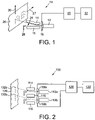
- the CIJ printer 10 of Figure 1 comprises an ink drop generator 12 connected to an ink supply (not shown), deflection means in the form of a pair of elongate deflection plates 14 and 16 connected to a high voltage power supply (not shown), a charge electrode 18 connected to a controller 20 and input means in the form of a touch screen display 22 that operates as a GUI for the controller 20.
- the ink drop generator 12 In use of the printer, the ink drop generator 12 generates a stream of drops of ink, denoted generally by reference numeral 24.
- the controller 20 receives image data from a data source (not shown) and, in response to movement of a substrate 26 in a transport direction (denoted in Figure 1 by arrow 27) relative to the printer 10, prints a series of strokes of ink dots on the substrate in accordance with the image data, by causing the charge electrode 18 to apply a 0 - 285 V variable charging voltage to selected ones of the drops generated by the drop generator.
- the resulting charged drops are deflected by an electrostatic field between the deflection plates 14 and 16 and reach the substrate 26. Ink drops to which no charging voltage is applied are caught by a gutter 28 and returned to the ink supply.
- the CIJ printer 10 differs from known CIJ printers in the operation of the controller 20, which presents to a user via the touch screen display 22 an adjustable offset setting and an adjustable print height scaling factor setting.
- variable voltage applied to drops that are to be printed varies between a minimum voltage V LDD of 50 V corresponding to a least deflected drop and a maximum voltage V MDD of 200 V corresponding to a most deflected drop.
- the resulting deflection constant k is 18.43 V/mm.
- the GUI would show the offset setting to be adjustable over the range -1.0 mm to +8.9 mm, whereas if the print height scaling factor setting were adjusted to 140 % while maintaining the offset setting at 0 mm, the GUI would show the offset setting to be adjustable over the range -1.0 mm to +0.2 mm.
- the GUI would show the print height scaling factor to be adjustable over the range 60 % to 156 %, whereas if the offset setting were adjusted to +4.0 mm while maintaining the print height scaling factor setting at 100 %, the GUI would show the print height scaling factor to be adjustable over the range 60 % to 104 %.
- the lower limits of adjustment of the offset setting and the print height scaling factor setting are fixed at -1.0 mm and 60 %, respectively, by the firmware of the printer, and do not change in response to adjustment of the other setting.
- the offset setting is set to 0 mm and the print height scaling factor setting is set to 100 %
- a voltage of 200 V is applied to the drop by the charge electrode 18, which causes the drop to be printed at a default MDD drop position on the substrate.
- a voltage of 240 V (200 ⁇ 120 %) is applied to the drop, which causes the drop to be printed at a scaled MDD drop position, which is displaced by 20 % further in the stroke direction from a notional origin than the default MDD drop position.
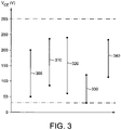
- the CIJ printer 100 of Figure 2 comprises first and second ink drop generators 112a and 112b connected to an ink supply (not shown), respective first and second elongate deflection plates 114 and 116 connected to a high voltage power supply (not shown), a common elongate deflection plate 115 connected to electrical ground, respective charge electrodes 118a and 118b connected to a controller 120 and a touch screen display 122 that operates as a GUI for the controller 120.
- the operation of the printer 100 of Figure 2 is the same as that of printer 10 of Figure 1 , except that the GUI presents to the user an adjustable offset setting and an adjustable print height scaling factor setting for each of the first and second drop generators 112a and 112b, and the controller 120 controls the voltages applied to the drops by the charge electrodes 118a and 118b, so as to control an offset in the stroke direction and print height scaling factor of two parallel images printed on a substrate 126 by the printer 100.
- the voltage applied to a drop by charge electrode 118a to print a particular dot (e.g., that denoted by reference numeral 132a in Figure 2 ) of a stroke will have the same magnitude as, but opposite polarity to, the voltage applied to a drop by charge electrode 118b to print the corresponding particular dot (i.e., that denoted by reference numeral 132b in Figure 2 ) of a stroke.
- FIG. 3 shows the ranges of charge electrode voltages (V CE ) applied to ink drops by the charge electrode for various print height scaling factor and offset settings.
- the upper end of each of the voltage ranges 300, 310, 320, 330 and 340 represents the charge electrode voltage that would be applied to a most deflected drop, and the lower end represents the charge electrode voltage that would be applied to a least deflected drop.
- the range denoted by reference numeral 300 is 50 V to 200 V, which corresponds to an offset setting of 0 mm and a print height scaling factor of 100 %.
- the range denoted by reference numeral 310 is 86.86 V to 236.86 V, which corresponds to an offset setting of +2.0 mm and a print height scaling factor of 100 %.
- the range denoted by reference numeral 320 is 60 V to 240 V, which corresponds to an offset setting of 0 mm and a print height scaling factor of 120 %.
- the range denoted by reference numeral 330 is 30 V to 120 V, which corresponds to an offset setting of 0 mm and a print height scaling factor of 60 %.
- the range denoted by reference numeral 340 is 113.72 V to 233.72 V, which corresponds to an offset setting of +4.0 mm and a print height scaling factor of 80 %.
Landscapes
- Engineering & Computer Science (AREA)
- Multimedia (AREA)
- Signal Processing (AREA)
- Particle Formation And Scattering Control In Inkjet Printers (AREA)
- Ink Jet (AREA)
Description
- This invention relates to a continuous inkjet (CIJ) printer, to a method of operating a CIJ printer, and to a computer program executable by a CIJ printer to carry out such a method.
- A CIJ printer prints an image on a substrate, typically packaging of a product on a production line, by printing a series of strokes of ink dots in a stroke direction on the substrate as the substrate moves in a transport direction perpendicular to the stroke direction.
- It is often required to adjust (or introduce) an offset in the stroke direction of the series of strokes of ink dots, the offset being a displacement of each ink dot in the stroke direction from a default position on the substrate, particularly where the CIJ printer is capable of printing two strokes of ink dots at the same time, for example so as to control a size of a gap between two images printed on the substrate by the printer.
- To date, such adjustment has been carried out by moving a print head of the printer relative to the substrate in the stroke direction, which requires time consuming adjustment of mounting brackets and the like, or, where the printer is capable of printing two strokes of ink dots at the same time, moving the print head towards or away from the substrate. In addition to requiring adjustment of mounting brackets and the like, this approach has the disadvantage that, as a side effect, changing the distance of the print head from the substrate changes the size of the resulting image on the substrate.
- CIJ printers that can adjust print character height by adjusting the value of the charging voltage to be applied to their charging electrodes are known.
US 2012/0194586 , for example, is concerned with such a printer. Adjusting print character height in this way involves changing the lengths of strokes of ink dots printed on a substrate by changing the distances in the stroke direction between the ink dots of the strokes. This is different from adjusting or introducing an offset in the stroke direction, where each ink dot of a stroke is displaced by an offset in the stroke direction from a default position on the substrate, but the lengths of the strokes of ink dots printed on the substrate are unchanged. -
EP 2 881 258 ,EP 2 166 472 andEP 0 481 797 - According to a first aspect of the invention there is provided a continuous inkjet printer according to claim 1
- The invention can provide a CIJ printer that enables an offset in a stroke direction of an image printed by the printer to be adjusted without adjusting mounting brackets and the like.
- In the preferred embodiments, the deflection means comprise a charge electrode operable to impart electrical charges to the ink drops, electrostatic field generating means operable to generate an electric field for deflecting charged drops, and a controller operable to control the magnitudes of the electrical charges imparted to the ink drops by the charge electrode.
- The electrostatic field generating means may advantageously comprise a pair of electrodes arranged such that in use of the printer the stream of drops passes between the electrodes.
- In the preferred embodiments, the electrostatic field generating means comprise a pair of elongate deflection plates arranged such that in use of the printer the stream of drops passes between and along the lengths of the deflection plates.
- Where the deflection means comprise the charge electrode, electrostatic field generating means and controller, the controller is operable to direct a drop to an offset print position by causing the charge electrode to impart an electrical charge to the drop, a magnitude of the electrical charge imparted to the drop being increased or decreased by a predetermined amount in dependence upon the indication of the offset relative to a magnitude of the electrical charge that would be imparted to the drop by the charge electrode to direct the drop to the corresponding default print position.
- The magnitudes of the electrical charges imparted to the drops are determined by a variable charging voltage applied to the charge electrode.
- There are minimum and maximum displacements of drops in the stroke direction relative to an origin, and drops displaced by less than the minimum displacement or more than the maximum displacement will not reach a substrate.
- In a typical CIJ printer, drops that are to be directed to the gutter have no electrical charge imparted to them by the charge electrode. Drops that are to be printed have electrical charges of stepwise increasing magnitude imparted to them, the magnitudes of the electrical charges determining the displacements of the drops from the origin in the stroke direction on a substrate. The drops to which the electrical charges of the least magnitude are imparted are the least deflected drops (LDDs) and the drops to which the electrical charges of the greatest magnitude are imparted are the most deflected drops (MDDs).
- A negative displacement of the offset print positions in the stroke direction, i.e., towards the origin, is obtained by decreasing the magnitudes of the electrical charges imparted to the drops relative to those that would be imparted to the drops to direct them to the default print positions, whereas a positive displacement of the offset print positions in the stroke direction, i.e., away from the origin, is obtained by increasing the magnitudes of the electrical charges imparted to the drops.
- The maximum negative displacement of the offset print positions obtainable by decreasing the magnitudes of the electrical charges imparted to the drops is determined by the minimum displacement of drops in the stroke direction relative to the origin, because drops that are displaced by less than the minimum displacement will collide with the gutter instead of reaching a substrate.
- Where the electrostatic field generating means comprise the pair of elongate plates, the maximum positive displacement of the offset print positions obtainable by increasing the magnitudes of the electrical charges imparted to the drops is determined by the maximum displacement of drops in the stroke direction relative to the origin, because drops that are displaced by more than the maximum displacement will collide with one of the deflection plates instead of reaching a substrate.
- Preferably, therefore, the input means are operable to receive an indication of an offset within a predetermined range of offsets.
- In the preferred embodiments the controller operable to control the magnitudes of the electrical charges imparted to the ink drops by the charge electrode is operable to apply voltages with magnitudes between a minimum magnitude and a maximum magnitude to the charge electrode.
- While various implementations are envisaged for the input means, such as a rotary switch, preferably the printer includes a graphical user interface (GUI) and the input means comprise an adjustable setting within the GUI.
- Where the printer includes the GUI, the adjustable setting is preferably constrained to be adjustable only within a range corresponding to the predetermined range of offsets.
- In the preferred embodiments the predetermined range of offsets correspond to a range of voltage magnitudes between the minimum magnitude and the maximum magnitude of the voltage applicable to the charge electrode by the controller.
- In the preferred embodiments, the printer includes input means operable to receive an indication of a print height scaling factor and the deflection means are operable, in dependence upon the indication of the print height scaling factor, to direct a drop that would otherwise be directed to a default print position to a scaled print position on a substrate, the scaled print position being displaced from the origin in the stroke direction by a displacement corresponding to a displacement from the origin of the default print position when scaled by the print height scaling factor.
- In the preferred embodiments, the deflection means are operable, in dependence upon the indication of the print height scaling factor, to direct each drop of at least a majority of the drops that would otherwise be directed to one of the default print positions to one of a plurality of scaled print positions on a substrate, each scaled print position corresponding to one of the default print positions and being displaced from the origin in the stroke direction by a displacement corresponding to a displacement from the origin of the corresponding default print position when scaled by the print height scaling factor.
- Where the printer includes input means operable to receive indications of both the offset and the print height scaling factor, there is an inverse relationship between the available offset and the available print height scaling factor. That is to say, if a large print height scaling factor is specified, given that there is a maximum magnitude of voltage that can be applied to the charge electrode by the controller, the available positive offset is small. Conversely, if a large positive offset is specified, the available print height scaling factor (above 100%) is small, for the same reason.
- In the preferred embodiments, the printer includes a GUI and the input means comprise adjustable settings for the offset and the print height scaling factor.
- In the preferred embodiments, the adjustable settings are constrained to be adjustable only within a range determined by the printer, and the printer is operable, in response to adjustment of one of the settings for the offset and the print height scaling factor, to modify the range within which the other of the settings for the offset and the print height scaling factor is constrained to be adjustable.
- The printer may advantageously comprise a further ink drop generator and further deflection means and the input means be operable to receive an indication of an offset for each deflection means, and each deflection means be operable to direct a drop that would otherwise be directed to a default print position to a respective offset print position on a substrate.
- The invention can further provide a CIJ printer that enables a gap between images printed by the printer to be adjusted without adjusting mounting brackets and the like.
- According to a second aspect of the invention, there is provided a method of operating a continuous inkjet printer according to claim 13.
- According to a third aspect of the invention, there is provided a computer program executable by a continuous inkjet printer to cause the printer to carry out the method of the second aspect of the invention.
- The invention will now be described, by way of example, with reference to the attached drawing figures, in which:
-
Figure 1 is a schematic diagram of a first embodiment of a CIJ printer in accordance with the invention; -
Figure 2 is a schematic diagram of a second embodiment of a CIJ printer in accordance with the invention; and -
Figure 3 is a graph of charge electrode voltage ranges for various print height scaling factor and offset settings. - The
CIJ printer 10 ofFigure 1 comprises anink drop generator 12 connected to an ink supply (not shown), deflection means in the form of a pair ofelongate deflection plates charge electrode 18 connected to acontroller 20 and input means in the form of atouch screen display 22 that operates as a GUI for thecontroller 20. - In use of the printer, the
ink drop generator 12 generates a stream of drops of ink, denoted generally byreference numeral 24. Thecontroller 20 receives image data from a data source (not shown) and, in response to movement of asubstrate 26 in a transport direction (denoted inFigure 1 by arrow 27) relative to theprinter 10, prints a series of strokes of ink dots on the substrate in accordance with the image data, by causing thecharge electrode 18 to apply a 0 - 285 V variable charging voltage to selected ones of the drops generated by the drop generator. The resulting charged drops are deflected by an electrostatic field between thedeflection plates substrate 26. Ink drops to which no charging voltage is applied are caught by agutter 28 and returned to the ink supply. - In the
CIJ printer 10 shown inFigure 1 , the greater the magnitude of the variable charging voltage applied to a drop, the greater will be the deflection of that drop towards thedeflection plate 14, and the greater will be the displacement of the resulting printed drop from an origin in a stroke direction (denoted inFigure 1 by arrow 30). - The operation of the CIJ printer as so far described is conventional and will be familiar to those skilled in the CIJ printer art.
- The
CIJ printer 10 differs from known CIJ printers in the operation of thecontroller 20, which presents to a user via thetouch screen display 22 an adjustable offset setting and an adjustable print height scaling factor setting. - The following description assumes that, in an initial setup step, a drop diameter D (in mm) produced by the printer on a substrate and a height h (in mm) of print produced by the printer on the substrate have been stored by the
controller 20. - In normal use of the
CIJ printer 10, i.e., without any adjustment to the offset setting or print height scaling factor setting, the variable voltage applied to drops that are to be printed varies between a minimum voltage V LDD of 50 V corresponding to a least deflected drop and a maximum voltage V MDD of 200 V corresponding to a most deflected drop. - As part of the initial setup step, the
controller 20 calculates a deflection constant k using the formula:
- Assuming for illustrative purposes a drop diameter D of 0.26 mm and a print height h of 8.4 mm, the resulting deflection constant k is 18.43 V/mm.
- Assuming also that there has not yet been any adjustment of the offset setting or print height scaling factor setting, i.e., the offset setting is 0 mm and the print height scaling factor setting is 100 %, the GUI shows the offset setting to be adjustable over the range -1.0 mm to +max_offset, where max_offset is calculated using the formula:

- The GUI shows the print height scaling factor setting to be adjustable over the range 60 % to max_print_height_scaling_factor, where max_print_height_scaling_factor is calculated using the formula:

- If the print height scaling factor setting were adjusted to 60 % while maintaining the offset setting at 0 mm, the GUI would show the offset setting to be adjustable over the range -1.0 mm to +8.9 mm, whereas if the print height scaling factor setting were adjusted to 140 % while maintaining the offset setting at 0 mm, the GUI would show the offset setting to be adjustable over the range -1.0 mm to +0.2 mm.
- If, on the other hand, the offset setting were adjusted to -1.0 mm while maintaining the print height scaling factor setting at 100 %, the GUI would show the print height scaling factor to be adjustable over the range 60 % to 156 %, whereas if the offset setting were adjusted to +4.0 mm while maintaining the print height scaling factor setting at 100 %, the GUI would show the print height scaling factor to be adjustable over the range 60 % to 104 %.
- For the avoidance of doubt, the lower limits of adjustment of the offset setting and the print height scaling factor setting are fixed at -1.0 mm and 60 %, respectively, by the firmware of the printer, and do not change in response to adjustment of the other setting.
- By way of illustration, if the offset setting is set to 0 mm and the print height scaling factor setting is set to 100 %, in order to print a most deflected drop (MDD), a voltage of 200 V is applied to the drop by the
charge electrode 18, which causes the drop to be printed at a default MDD drop position on the substrate. - If the offset setting is set to +2.0 mm but the print height scaling factor setting remains set to 100 %, a voltage of 236.86 V (200 + (2 ∗ 18.43)) is applied to the drop, which causes the drop to be printed at an offset MDD drop position, which is displaced by 2 mm in the stroke direction from the default MDD drop position.
- If the print height scaling factor setting is set to 120 % but the offset setting remains set to 0 mm, a voltage of 240 V (200 ∗ 120 %) is applied to the drop, which causes the drop to be printed at a scaled MDD drop position, which is displaced by 20 % further in the stroke direction from a notional origin than the default MDD drop position.
- The
CIJ printer 100 ofFigure 2 comprises first and secondink drop generators elongate deflection plates elongate deflection plate 115 connected to electrical ground,respective charge electrodes controller 120 and atouch screen display 122 that operates as a GUI for thecontroller 120. - The operation of the
printer 100 ofFigure 2 is the same as that ofprinter 10 ofFigure 1 , except that the GUI presents to the user an adjustable offset setting and an adjustable print height scaling factor setting for each of the first andsecond drop generators controller 120 controls the voltages applied to the drops by thecharge electrodes substrate 126 by theprinter 100. It will be apparent that the voltage applied to a drop bycharge electrode 118a to print a particular dot (e.g., that denoted byreference numeral 132a inFigure 2 ) of a stroke will have the same magnitude as, but opposite polarity to, the voltage applied to a drop bycharge electrode 118b to print the corresponding particular dot (i.e., that denoted byreference numeral 132b inFigure 2 ) of a stroke. -
Figure 3 shows the ranges of charge electrode voltages (VCE) applied to ink drops by the charge electrode for various print height scaling factor and offset settings. The upper end of each of the voltage ranges 300, 310, 320, 330 and 340 represents the charge electrode voltage that would be applied to a most deflected drop, and the lower end represents the charge electrode voltage that would be applied to a least deflected drop. - The range denoted by
reference numeral 300 is 50 V to 200 V, which corresponds to an offset setting of 0 mm and a print height scaling factor of 100 %. - The range denoted by
reference numeral 310 is 86.86 V to 236.86 V, which corresponds to an offset setting of +2.0 mm and a print height scaling factor of 100 %. - The range denoted by
reference numeral 320 is 60 V to 240 V, which corresponds to an offset setting of 0 mm and a print height scaling factor of 120 %. - The range denoted by
reference numeral 330 is 30 V to 120 V, which corresponds to an offset setting of 0 mm and a print height scaling factor of 60 %. - The range denoted by
reference numeral 340 is 113.72 V to 233.72 V, which corresponds to an offset setting of +4.0 mm and a print height scaling factor of 80 %. - It will be apparent that the above description relates only to two embodiments of the invention, and that the invention is defined by the claims.
Claims (14)
- A continuous inkjet printer (10; 100) comprising an ink drop generator (12; 112a, 112b) operable to generate a stream (24) of ink drops, and deflection means (14, 16, 18, 20; 114, 115, 116, 118a, 118b, 120) operable to direct each drop of the stream (24) of ink drops either to a gutter (28) or to one of a plurality of default print positions in a stroke direction (30) on a substrate (26; 126), characterised in that the printer includes input means (22; 122) operable to receive an indication of an offset in the stroke direction (30) and the deflection means (14, 16, 18, 20; 114, 115, 116, 118a, 118b, 120) are operable, in dependence upon the indication of the offset, to direct each drop of at least a majority of the drops that would otherwise be directed to one of the plurality of default print positions in the stroke direction (30) to an offset print position on a substrate (26; 126), each offset print position corresponding to one of the plurality of default print positions and being displaced in the stroke direction (30) by the offset from the corresponding default print position.
- A continuous inkjet printer (10; 100) according to claim 1, wherein the deflection means (14, 16, 18, 20; 114, 115, 116, 118a, 118b, 120) are operable, in dependence upon the indication of the offset, to direct each drop that would otherwise be directed to one of the default print positions to one of a plurality of offset print positions on a substrate (26; 126).
- A continuous inkjet printer (10; 100) according to claim 1 or 2, wherein the deflection means (14, 16, 18, 20; 114, 115, 116, 118a, 118b, 120) comprise a charge electrode (18; 118a, 118b) operable to impart electrical charges to the ink drops, electrostatic field generating means (14, 16; 114, 115, 116) operable to generate an electric field for deflecting charged drops, and a controller (20; 120) operable to control the magnitudes of the electrical charges imparted to the ink drops by the charge electrode (18; 118a, 118b).
- A continuous inkjet printer (10; 100) according to any preceding claim, wherein the electrostatic field generating means comprise a pair of elongate deflection plates (14, 16; 114, 115, 116) arranged such that in use of the printer the stream (24) of drops passes between and substantially parallel to the lengths of the deflection plates (14, 16; 114, 115, 116) .
- A continuous inkjet printer (10; 100) according to any preceding claim, wherein the input means (22; 122) are operable to receive an indication of an offset within a predetermined range of offsets.
- A continuous inkjet printer (10; 100) according to claim 5, wherein the printer (10; 100) includes a graphical user interface (GUI) and the input means (22; 122) comprise an adjustable setting within the GUI.
- A continuous inkjet printer (10; 100) according to claim 6, wherein the adjustable setting is constrained to be adjustable only within a range corresponding to the predetermined range of offsets.
- A continuous inkjet printer (10; 100) according to any preceding claim, wherein the printer (10; 100) includes input means (22; 122) operable to receive an indication of a print height scaling factor and the deflection means (14, 16, 18, 20; 114, 115, 116, 118a, 118b, 120) are operable, in dependence upon the indication of the print height scaling factor, to direct a drop that would otherwise be directed to a default print position to a scaled print position on a substrate (26; 126), the scaled print position being displaced from the origin in the stroke direction (30) by a displacement corresponding to a displacement from the origin of the default print position when scaled by the print height scaling factor.
- A continuous inkjet printer (10; 100) according to claim 8, wherein the deflection means (14, 16, 18, 20; 114, 115, 116, 118a, 118b, 120) are operable, in dependence upon the indication of the print height scaling factor, to direct each drop that would otherwise be directed to one of the default print positions to one of a plurality of scaled print positions on a substrate (26; 126), each scaled print position corresponding to one of the default print positions and being displaced from the origin in the stroke direction (30) by a displacement corresponding to a displacement from the origin of the corresponding default print position when scaled by the print height scaling factor.
- A continuous inkjet printer (10; 100) according to claim 8 or 9, wherein the printer (10; 100) includes a GUI and the input means (22; 122) comprise adjustable settings for the offset and the print height scaling factor.
- A continuous inkjet printer (10; 100) according to claim 10, wherein the adjustable settings are constrained to be adjustable only within a range determined by the printer (10; 100), and the printer (10; 100) is operable, in response to adjustment of one of the settings for the offset and the print height scaling factor, to modify the range within which the other of the settings for the offset and the print height scaling factor is constrained to be adjustable.
- A continuous inkjet printer (100) according to any preceding claim, wherein the printer (100) comprises a further ink drop generator (112b) and further deflection means (116, 118b) and the input means (122) are operable to receive an indication of an offset for each deflection means (114, 115, 116, 118a, 118b, 120), and each deflection means (114, 115, 116, 118a, 118b, 120) are operable to direct a drop that would otherwise be directed to a default print position to a respective offset print position on a substrate (126).
- A method of operating a continuous inkjet printer (10; 100) comprising an ink drop generator (12; 112a, 112b) operable to generate a stream (24) of ink drops, and deflection means (14, 16, 18, 20; 114, 115, 116, 118a, 118b, 120) operable to direct each drop of the stream (24) of drops either to a gutter (28) or to one of a plurality of default print positions in a stroke direction (30) on a substrate (26; 126), characterised in that the method comprises receiving an indication of an offset in the stroke direction (30) and causing the deflection means (14, 16, 18, 20; 114, 115, 116, 118a, 118b, 120), in dependence upon the indication of the offset, to direct each drop of at least a majority of the drops that would otherwise be directed to one of the plurality of default print positions to an offset print position in the stroke direction (30) on the substrate (26; 126), each offset print position corresponding to one of the plurality of default print positions and being displaced in the stroke direction (30) by the offset from the corresponding default print position.
- A computer program executable by a continuous inkjet printer (10; 100) to cause the printer (10; 100) to carry out the method of claim 13.
Applications Claiming Priority (2)
| Application Number | Priority Date | Filing Date | Title |
|---|---|---|---|
| GB201810587A GB2575077A (en) | 2018-06-28 | 2018-06-28 | Stroke direction offset adjustment |
| PCT/GB2019/000090 WO2020002865A1 (en) | 2018-06-28 | 2019-06-27 | Stroke direction offset adjustment |
Publications (2)
| Publication Number | Publication Date |
|---|---|
| EP3814146A1 EP3814146A1 (en) | 2021-05-05 |
| EP3814146B1 true EP3814146B1 (en) | 2022-08-10 |
Family
ID=63143707
Family Applications (1)
| Application Number | Title | Priority Date | Filing Date |
|---|---|---|---|
| EP19748879.4A Active EP3814146B1 (en) | 2018-06-28 | 2019-06-27 | Stroke direction offset adjustment |
Country Status (4)
| Country | Link |
|---|---|
| US (1) | US11220103B2 (en) |
| EP (1) | EP3814146B1 (en) |
| GB (1) | GB2575077A (en) |
| WO (1) | WO2020002865A1 (en) |
Family Cites Families (9)
| Publication number | Priority date | Publication date | Assignee | Title |
|---|---|---|---|---|
| US4119973A (en) * | 1977-09-06 | 1978-10-10 | The Mead Corporation | Fault detection and compensation circuit for ink jet printer |
| CA2049454C (en) * | 1990-10-18 | 1999-01-05 | Michael E. Stamer | Automatic character height control for ink jet printers |
| GB9819081D0 (en) * | 1998-09-03 | 1998-10-28 | Videojet Systems Int | An ink jet printing system |
| US7758171B2 (en) * | 2007-03-19 | 2010-07-20 | Eastman Kodak Company | Aerodynamic error reduction for liquid drop emitters |
| JP5202203B2 (en) | 2008-09-17 | 2013-06-05 | 株式会社日立産機システム | Inkjet recording device |
| CN102470669B (en) * | 2009-08-11 | 2015-02-18 | 株式会社日立产机系统 | Inkjet recording device and printing head |
| US8646883B2 (en) * | 2012-03-20 | 2014-02-11 | Eastman Kodak Company | Drop placement error reduction in electrostatic printer |
| JP6058938B2 (en) | 2012-07-30 | 2017-01-11 | 株式会社日立産機システム | Inkjet recording apparatus and printing control method |
| ES2874144T3 (en) | 2016-07-05 | 2021-11-04 | Occidental Chem Co | Photochlorination of chloroform to carbon tetrachloride |
-
2018
- 2018-06-28 GB GB201810587A patent/GB2575077A/en not_active Withdrawn
-
2019
- 2019-06-27 US US17/256,335 patent/US11220103B2/en active Active
- 2019-06-27 EP EP19748879.4A patent/EP3814146B1/en active Active
- 2019-06-27 WO PCT/GB2019/000090 patent/WO2020002865A1/en not_active Ceased
Also Published As
| Publication number | Publication date |
|---|---|
| GB2575077A (en) | 2020-01-01 |
| US11220103B2 (en) | 2022-01-11 |
| EP3814146A1 (en) | 2021-05-05 |
| GB201810587D0 (en) | 2018-08-15 |
| WO2020002865A1 (en) | 2020-01-02 |
| US20210146681A1 (en) | 2021-05-20 |
Similar Documents
| Publication | Publication Date | Title |
|---|---|---|
| EP3388240B1 (en) | Inkjet printing apparatus, inkjet head driving method, and driving waveform-designing method | |
| EP1287992B1 (en) | Ink jet printing apparatus and method | |
| US20080186350A1 (en) | Ink jet printer | |
| US8764169B2 (en) | Inkjet recording device and printing head | |
| US9358782B2 (en) | Liquid discharge apparatus | |
| US8613513B2 (en) | Sheet-medium conveying apparatus and image forming apparatus having a conveying belt with a charge pattern | |
| US10994536B2 (en) | Image recording apparatus | |
| US11220103B2 (en) | Stroke direction offset adjustment | |
| JP2018008451A (en) | Liquid discharge unit, liquid discharge device, drive voltage correction method, and drive voltage correction program | |
| EP1758740B1 (en) | System and method for auto-threshold adjustment for phasing | |
| CN100572071C (en) | Threshold automatic adjustment system and method for phase adjustment | |
| JP2010137528A (en) | Inkjet recording apparatus | |
| CN105058986A (en) | Cross printing method for CIJ ink-jet printer | |
| US9352558B2 (en) | Line type liquid discharge apparatus, control method of line type liquid discharge apparatus, and device driver, and printing system | |
| CN110202954B (en) | Printing device for material belt | |
| US6367909B1 (en) | Method and apparatus for reducing drop placement error in printers | |
| JP7146302B2 (en) | inkjet printer | |
| US20020075338A1 (en) | Ink jet recording device capable of controlling impact positions of ink droplets | |
| US9630401B2 (en) | Printhead calibration and printing | |
| HK1113112A (en) | System and method for auto-threshold adjustment for phasing | |
| JP2014012416A (en) | Inkjet recording apparatus | |
| JP2009179028A (en) | Inkjet recording device | |
| JP2011136528A (en) | Image recorder and image recording method | |
| JP2002210978A (en) | Ink recording device | |
| JP2008074578A (en) | Inkjet printer |
Legal Events
| Date | Code | Title | Description |
|---|---|---|---|
| STAA | Information on the status of an ep patent application or granted ep patent |
Free format text: STATUS: UNKNOWN |
|
| STAA | Information on the status of an ep patent application or granted ep patent |
Free format text: STATUS: THE INTERNATIONAL PUBLICATION HAS BEEN MADE |
|
| PUAI | Public reference made under article 153(3) epc to a published international application that has entered the european phase |
Free format text: ORIGINAL CODE: 0009012 |
|
| STAA | Information on the status of an ep patent application or granted ep patent |
Free format text: STATUS: REQUEST FOR EXAMINATION WAS MADE |
|
| 17P | Request for examination filed |
Effective date: 20210127 |
|
| AK | Designated contracting states |
Kind code of ref document: A1 Designated state(s): AL AT BE BG CH CY CZ DE DK EE ES FI FR GB GR HR HU IE IS IT LI LT LU LV MC MK MT NL NO PL PT RO RS SE SI SK SM TR |
|
| DAV | Request for validation of the european patent (deleted) | ||
| DAX | Request for extension of the european patent (deleted) | ||
| GRAP | Despatch of communication of intention to grant a patent |
Free format text: ORIGINAL CODE: EPIDOSNIGR1 |
|
| STAA | Information on the status of an ep patent application or granted ep patent |
Free format text: STATUS: GRANT OF PATENT IS INTENDED |
|
| RIC1 | Information provided on ipc code assigned before grant |
Ipc: B41J 2/03 20060101ALI20220103BHEP Ipc: B41J 2/075 20060101ALI20220103BHEP Ipc: B41J 2/02 20060101AFI20220103BHEP |
|
| INTG | Intention to grant announced |
Effective date: 20220201 |
|
| GRAJ | Information related to disapproval of communication of intention to grant by the applicant or resumption of examination proceedings by the epo deleted |
Free format text: ORIGINAL CODE: EPIDOSDIGR1 |
|
| STAA | Information on the status of an ep patent application or granted ep patent |
Free format text: STATUS: REQUEST FOR EXAMINATION WAS MADE |
|
| GRAP | Despatch of communication of intention to grant a patent |
Free format text: ORIGINAL CODE: EPIDOSNIGR1 |
|
| STAA | Information on the status of an ep patent application or granted ep patent |
Free format text: STATUS: GRANT OF PATENT IS INTENDED |
|
| INTC | Intention to grant announced (deleted) | ||
| INTG | Intention to grant announced |
Effective date: 20220330 |
|
| GRAS | Grant fee paid |
Free format text: ORIGINAL CODE: EPIDOSNIGR3 |
|
| GRAA | (expected) grant |
Free format text: ORIGINAL CODE: 0009210 |
|
| STAA | Information on the status of an ep patent application or granted ep patent |
Free format text: STATUS: THE PATENT HAS BEEN GRANTED |
|
| AK | Designated contracting states |
Kind code of ref document: B1 Designated state(s): AL AT BE BG CH CY CZ DE DK EE ES FI FR GB GR HR HU IE IS IT LI LT LU LV MC MK MT NL NO PL PT RO RS SE SI SK SM TR |
|
| REG | Reference to a national code |
Ref country code: AT Ref legal event code: REF Ref document number: 1510232 Country of ref document: AT Kind code of ref document: T Effective date: 20220815 Ref country code: CH Ref legal event code: EP |
|
| REG | Reference to a national code |
Ref country code: IE Ref legal event code: FG4D |
|
| REG | Reference to a national code |
Ref country code: DE Ref legal event code: R096 Ref document number: 602019018172 Country of ref document: DE |
|
| REG | Reference to a national code |
Ref country code: NL Ref legal event code: MP Effective date: 20220810 |
|
| REG | Reference to a national code |
Ref country code: LT Ref legal event code: MG9D |
|
| PG25 | Lapsed in a contracting state [announced via postgrant information from national office to epo] |
Ref country code: SE Free format text: LAPSE BECAUSE OF FAILURE TO SUBMIT A TRANSLATION OF THE DESCRIPTION OR TO PAY THE FEE WITHIN THE PRESCRIBED TIME-LIMIT Effective date: 20220810 Ref country code: RS Free format text: LAPSE BECAUSE OF FAILURE TO SUBMIT A TRANSLATION OF THE DESCRIPTION OR TO PAY THE FEE WITHIN THE PRESCRIBED TIME-LIMIT Effective date: 20220810 Ref country code: PT Free format text: LAPSE BECAUSE OF FAILURE TO SUBMIT A TRANSLATION OF THE DESCRIPTION OR TO PAY THE FEE WITHIN THE PRESCRIBED TIME-LIMIT Effective date: 20221212 Ref country code: NO Free format text: LAPSE BECAUSE OF FAILURE TO SUBMIT A TRANSLATION OF THE DESCRIPTION OR TO PAY THE FEE WITHIN THE PRESCRIBED TIME-LIMIT Effective date: 20221110 Ref country code: NL Free format text: LAPSE BECAUSE OF FAILURE TO SUBMIT A TRANSLATION OF THE DESCRIPTION OR TO PAY THE FEE WITHIN THE PRESCRIBED TIME-LIMIT Effective date: 20220810 Ref country code: LV Free format text: LAPSE BECAUSE OF FAILURE TO SUBMIT A TRANSLATION OF THE DESCRIPTION OR TO PAY THE FEE WITHIN THE PRESCRIBED TIME-LIMIT Effective date: 20220810 Ref country code: LT Free format text: LAPSE BECAUSE OF FAILURE TO SUBMIT A TRANSLATION OF THE DESCRIPTION OR TO PAY THE FEE WITHIN THE PRESCRIBED TIME-LIMIT Effective date: 20220810 Ref country code: FI Free format text: LAPSE BECAUSE OF FAILURE TO SUBMIT A TRANSLATION OF THE DESCRIPTION OR TO PAY THE FEE WITHIN THE PRESCRIBED TIME-LIMIT Effective date: 20220810 |
|
| REG | Reference to a national code |
Ref country code: AT Ref legal event code: MK05 Ref document number: 1510232 Country of ref document: AT Kind code of ref document: T Effective date: 20220810 |
|
| PG25 | Lapsed in a contracting state [announced via postgrant information from national office to epo] |
Ref country code: PL Free format text: LAPSE BECAUSE OF FAILURE TO SUBMIT A TRANSLATION OF THE DESCRIPTION OR TO PAY THE FEE WITHIN THE PRESCRIBED TIME-LIMIT Effective date: 20220810 Ref country code: IS Free format text: LAPSE BECAUSE OF FAILURE TO SUBMIT A TRANSLATION OF THE DESCRIPTION OR TO PAY THE FEE WITHIN THE PRESCRIBED TIME-LIMIT Effective date: 20221210 Ref country code: HR Free format text: LAPSE BECAUSE OF FAILURE TO SUBMIT A TRANSLATION OF THE DESCRIPTION OR TO PAY THE FEE WITHIN THE PRESCRIBED TIME-LIMIT Effective date: 20220810 Ref country code: GR Free format text: LAPSE BECAUSE OF FAILURE TO SUBMIT A TRANSLATION OF THE DESCRIPTION OR TO PAY THE FEE WITHIN THE PRESCRIBED TIME-LIMIT Effective date: 20221111 |
|
| PG25 | Lapsed in a contracting state [announced via postgrant information from national office to epo] |
Ref country code: SM Free format text: LAPSE BECAUSE OF FAILURE TO SUBMIT A TRANSLATION OF THE DESCRIPTION OR TO PAY THE FEE WITHIN THE PRESCRIBED TIME-LIMIT Effective date: 20220810 Ref country code: RO Free format text: LAPSE BECAUSE OF FAILURE TO SUBMIT A TRANSLATION OF THE DESCRIPTION OR TO PAY THE FEE WITHIN THE PRESCRIBED TIME-LIMIT Effective date: 20220810 Ref country code: ES Free format text: LAPSE BECAUSE OF FAILURE TO SUBMIT A TRANSLATION OF THE DESCRIPTION OR TO PAY THE FEE WITHIN THE PRESCRIBED TIME-LIMIT Effective date: 20220810 Ref country code: DK Free format text: LAPSE BECAUSE OF FAILURE TO SUBMIT A TRANSLATION OF THE DESCRIPTION OR TO PAY THE FEE WITHIN THE PRESCRIBED TIME-LIMIT Effective date: 20220810 Ref country code: CZ Free format text: LAPSE BECAUSE OF FAILURE TO SUBMIT A TRANSLATION OF THE DESCRIPTION OR TO PAY THE FEE WITHIN THE PRESCRIBED TIME-LIMIT Effective date: 20220810 Ref country code: AT Free format text: LAPSE BECAUSE OF FAILURE TO SUBMIT A TRANSLATION OF THE DESCRIPTION OR TO PAY THE FEE WITHIN THE PRESCRIBED TIME-LIMIT Effective date: 20220810 |
|
| REG | Reference to a national code |
Ref country code: DE Ref legal event code: R097 Ref document number: 602019018172 Country of ref document: DE |
|
| PG25 | Lapsed in a contracting state [announced via postgrant information from national office to epo] |
Ref country code: SK Free format text: LAPSE BECAUSE OF FAILURE TO SUBMIT A TRANSLATION OF THE DESCRIPTION OR TO PAY THE FEE WITHIN THE PRESCRIBED TIME-LIMIT Effective date: 20220810 Ref country code: EE Free format text: LAPSE BECAUSE OF FAILURE TO SUBMIT A TRANSLATION OF THE DESCRIPTION OR TO PAY THE FEE WITHIN THE PRESCRIBED TIME-LIMIT Effective date: 20220810 |
|
| P01 | Opt-out of the competence of the unified patent court (upc) registered |
Effective date: 20230502 |
|
| PLBE | No opposition filed within time limit |
Free format text: ORIGINAL CODE: 0009261 |
|
| STAA | Information on the status of an ep patent application or granted ep patent |
Free format text: STATUS: NO OPPOSITION FILED WITHIN TIME LIMIT |
|
| PG25 | Lapsed in a contracting state [announced via postgrant information from national office to epo] |
Ref country code: AL Free format text: LAPSE BECAUSE OF FAILURE TO SUBMIT A TRANSLATION OF THE DESCRIPTION OR TO PAY THE FEE WITHIN THE PRESCRIBED TIME-LIMIT Effective date: 20220810 |
|
| 26N | No opposition filed |
Effective date: 20230511 |
|
| PG25 | Lapsed in a contracting state [announced via postgrant information from national office to epo] |
Ref country code: SI Free format text: LAPSE BECAUSE OF FAILURE TO SUBMIT A TRANSLATION OF THE DESCRIPTION OR TO PAY THE FEE WITHIN THE PRESCRIBED TIME-LIMIT Effective date: 20220810 |
|
| PG25 | Lapsed in a contracting state [announced via postgrant information from national office to epo] |
Ref country code: MC Free format text: LAPSE BECAUSE OF FAILURE TO SUBMIT A TRANSLATION OF THE DESCRIPTION OR TO PAY THE FEE WITHIN THE PRESCRIBED TIME-LIMIT Effective date: 20220810 |
|
| PG25 | Lapsed in a contracting state [announced via postgrant information from national office to epo] |
Ref country code: MC Free format text: LAPSE BECAUSE OF FAILURE TO SUBMIT A TRANSLATION OF THE DESCRIPTION OR TO PAY THE FEE WITHIN THE PRESCRIBED TIME-LIMIT Effective date: 20220810 |
|
| REG | Reference to a national code |
Ref country code: CH Ref legal event code: PL |
|
| REG | Reference to a national code |
Ref country code: BE Ref legal event code: MM Effective date: 20230630 |
|
| PG25 | Lapsed in a contracting state [announced via postgrant information from national office to epo] |
Ref country code: LU Free format text: LAPSE BECAUSE OF NON-PAYMENT OF DUE FEES Effective date: 20230627 |
|
| REG | Reference to a national code |
Ref country code: IE Ref legal event code: MM4A |
|
| PG25 | Lapsed in a contracting state [announced via postgrant information from national office to epo] |
Ref country code: LU Free format text: LAPSE BECAUSE OF NON-PAYMENT OF DUE FEES Effective date: 20230627 |
|
| PG25 | Lapsed in a contracting state [announced via postgrant information from national office to epo] |
Ref country code: IE Free format text: LAPSE BECAUSE OF NON-PAYMENT OF DUE FEES Effective date: 20230627 |
|
| PG25 | Lapsed in a contracting state [announced via postgrant information from national office to epo] |
Ref country code: IE Free format text: LAPSE BECAUSE OF NON-PAYMENT OF DUE FEES Effective date: 20230627 Ref country code: CH Free format text: LAPSE BECAUSE OF NON-PAYMENT OF DUE FEES Effective date: 20230630 |
|
| PG25 | Lapsed in a contracting state [announced via postgrant information from national office to epo] |
Ref country code: BE Free format text: LAPSE BECAUSE OF NON-PAYMENT OF DUE FEES Effective date: 20230630 |
|
| PG25 | Lapsed in a contracting state [announced via postgrant information from national office to epo] |
Ref country code: BG Free format text: LAPSE BECAUSE OF FAILURE TO SUBMIT A TRANSLATION OF THE DESCRIPTION OR TO PAY THE FEE WITHIN THE PRESCRIBED TIME-LIMIT Effective date: 20220810 |
|
| PG25 | Lapsed in a contracting state [announced via postgrant information from national office to epo] |
Ref country code: BG Free format text: LAPSE BECAUSE OF FAILURE TO SUBMIT A TRANSLATION OF THE DESCRIPTION OR TO PAY THE FEE WITHIN THE PRESCRIBED TIME-LIMIT Effective date: 20220810 |
|
| PG25 | Lapsed in a contracting state [announced via postgrant information from national office to epo] |
Ref country code: CY Free format text: LAPSE BECAUSE OF FAILURE TO SUBMIT A TRANSLATION OF THE DESCRIPTION OR TO PAY THE FEE WITHIN THE PRESCRIBED TIME-LIMIT; INVALID AB INITIO Effective date: 20190627 |
|
| PG25 | Lapsed in a contracting state [announced via postgrant information from national office to epo] |
Ref country code: HU Free format text: LAPSE BECAUSE OF FAILURE TO SUBMIT A TRANSLATION OF THE DESCRIPTION OR TO PAY THE FEE WITHIN THE PRESCRIBED TIME-LIMIT; INVALID AB INITIO Effective date: 20190627 |
|
| PG25 | Lapsed in a contracting state [announced via postgrant information from national office to epo] |
Ref country code: TR Free format text: LAPSE BECAUSE OF FAILURE TO SUBMIT A TRANSLATION OF THE DESCRIPTION OR TO PAY THE FEE WITHIN THE PRESCRIBED TIME-LIMIT Effective date: 20220810 |
|
| PGFP | Annual fee paid to national office [announced via postgrant information from national office to epo] |
Ref country code: GB Payment date: 20260617 Year of fee payment: 8 |
|
| PGFP | Annual fee paid to national office [announced via postgrant information from national office to epo] |
Ref country code: IT Payment date: 20260624 Year of fee payment: 8 |
|
| PGFP | Annual fee paid to national office [announced via postgrant information from national office to epo] |
Ref country code: DE Payment date: 20260618 Year of fee payment: 8 |
|
| PGFP | Annual fee paid to national office [announced via postgrant information from national office to epo] |
Ref country code: FR Payment date: 20260616 Year of fee payment: 8 |