EP3814093B1 - Free blow bottle design - Google Patents
Free blow bottle design Download PDFInfo
- Publication number
- EP3814093B1 EP3814093B1 EP19787404.3A EP19787404A EP3814093B1 EP 3814093 B1 EP3814093 B1 EP 3814093B1 EP 19787404 A EP19787404 A EP 19787404A EP 3814093 B1 EP3814093 B1 EP 3814093B1
- Authority
- EP
- European Patent Office
- Prior art keywords
- container
- preform
- free
- sidewall profile
- blow molding
- Prior art date
- Legal status (The legal status is an assumption and is not a legal conclusion. Google has not performed a legal analysis and makes no representation as to the accuracy of the status listed.)
- Active
Links
Images



Classifications
-
- B—PERFORMING OPERATIONS; TRANSPORTING
- B29—WORKING OF PLASTICS; WORKING OF SUBSTANCES IN A PLASTIC STATE IN GENERAL
- B29C—SHAPING OR JOINING OF PLASTICS; SHAPING OF MATERIAL IN A PLASTIC STATE, NOT OTHERWISE PROVIDED FOR; AFTER-TREATMENT OF THE SHAPED PRODUCTS, e.g. REPAIRING
- B29C49/00—Blow-moulding, i.e. blowing a preform or parison to a desired shape within a mould; Apparatus therefor
- B29C49/42—Component parts, details or accessories; Auxiliary operations
- B29C49/46—Component parts, details or accessories; Auxiliary operations characterised by using particular environment or blow fluids other than air
-
- B—PERFORMING OPERATIONS; TRANSPORTING
- B29—WORKING OF PLASTICS; WORKING OF SUBSTANCES IN A PLASTIC STATE IN GENERAL
- B29C—SHAPING OR JOINING OF PLASTICS; SHAPING OF MATERIAL IN A PLASTIC STATE, NOT OTHERWISE PROVIDED FOR; AFTER-TREATMENT OF THE SHAPED PRODUCTS, e.g. REPAIRING
- B29C49/00—Blow-moulding, i.e. blowing a preform or parison to a desired shape within a mould; Apparatus therefor
- B29C49/0042—Blow-moulding, i.e. blowing a preform or parison to a desired shape within a mould; Apparatus therefor without using a mould
-
- B—PERFORMING OPERATIONS; TRANSPORTING
- B29—WORKING OF PLASTICS; WORKING OF SUBSTANCES IN A PLASTIC STATE IN GENERAL
- B29C—SHAPING OR JOINING OF PLASTICS; SHAPING OF MATERIAL IN A PLASTIC STATE, NOT OTHERWISE PROVIDED FOR; AFTER-TREATMENT OF THE SHAPED PRODUCTS, e.g. REPAIRING
- B29C49/00—Blow-moulding, i.e. blowing a preform or parison to a desired shape within a mould; Apparatus therefor
- B29C49/02—Combined blow-moulding and manufacture of the preform or the parison
- B29C49/04—Extrusion blow-moulding
-
- B—PERFORMING OPERATIONS; TRANSPORTING
- B29—WORKING OF PLASTICS; WORKING OF SUBSTANCES IN A PLASTIC STATE IN GENERAL
- B29C—SHAPING OR JOINING OF PLASTICS; SHAPING OF MATERIAL IN A PLASTIC STATE, NOT OTHERWISE PROVIDED FOR; AFTER-TREATMENT OF THE SHAPED PRODUCTS, e.g. REPAIRING
- B29C49/00—Blow-moulding, i.e. blowing a preform or parison to a desired shape within a mould; Apparatus therefor
- B29C49/42—Component parts, details or accessories; Auxiliary operations
- B29C49/42398—Simulation of the blow-moulding process
- B29C49/42402—Simulation of the shaping process
-
- B—PERFORMING OPERATIONS; TRANSPORTING
- B65—CONVEYING; PACKING; STORING; HANDLING THIN OR FILAMENTARY MATERIAL
- B65D—CONTAINERS FOR STORAGE OR TRANSPORT OF ARTICLES OR MATERIALS, e.g. BAGS, BARRELS, BOTTLES, BOXES, CANS, CARTONS, CRATES, DRUMS, JARS, TANKS, HOPPERS, FORWARDING CONTAINERS; ACCESSORIES, CLOSURES, OR FITTINGS THEREFOR; PACKAGING ELEMENTS; PACKAGES
- B65D1/00—Rigid or semi-rigid containers having bodies formed in one piece, e.g. by casting metallic material, by moulding plastics, by blowing vitreous material, by throwing ceramic material, by moulding pulped fibrous material or by deep-drawing operations performed on sheet material
- B65D1/02—Bottles or similar containers with necks or like restricted apertures, designed for pouring contents
- B65D1/0223—Bottles or similar containers with necks or like restricted apertures, designed for pouring contents characterised by shape
-
- B—PERFORMING OPERATIONS; TRANSPORTING
- B29—WORKING OF PLASTICS; WORKING OF SUBSTANCES IN A PLASTIC STATE IN GENERAL
- B29C—SHAPING OR JOINING OF PLASTICS; SHAPING OF MATERIAL IN A PLASTIC STATE, NOT OTHERWISE PROVIDED FOR; AFTER-TREATMENT OF THE SHAPED PRODUCTS, e.g. REPAIRING
- B29C49/00—Blow-moulding, i.e. blowing a preform or parison to a desired shape within a mould; Apparatus therefor
- B29C49/42—Component parts, details or accessories; Auxiliary operations
- B29C49/46—Component parts, details or accessories; Auxiliary operations characterised by using particular environment or blow fluids other than air
- B29C2049/4602—Blowing fluids
- B29C2049/465—Blowing fluids being incompressible
-
- B—PERFORMING OPERATIONS; TRANSPORTING
- B29—WORKING OF PLASTICS; WORKING OF SUBSTANCES IN A PLASTIC STATE IN GENERAL
- B29C—SHAPING OR JOINING OF PLASTICS; SHAPING OF MATERIAL IN A PLASTIC STATE, NOT OTHERWISE PROVIDED FOR; AFTER-TREATMENT OF THE SHAPED PRODUCTS, e.g. REPAIRING
- B29C49/00—Blow-moulding, i.e. blowing a preform or parison to a desired shape within a mould; Apparatus therefor
- B29C49/42—Component parts, details or accessories; Auxiliary operations
- B29C49/78—Measuring, controlling or regulating
- B29C2049/7874—Preform or article shape, weight, defect or presence
-
- B—PERFORMING OPERATIONS; TRANSPORTING
- B29—WORKING OF PLASTICS; WORKING OF SUBSTANCES IN A PLASTIC STATE IN GENERAL
- B29C—SHAPING OR JOINING OF PLASTICS; SHAPING OF MATERIAL IN A PLASTIC STATE, NOT OTHERWISE PROVIDED FOR; AFTER-TREATMENT OF THE SHAPED PRODUCTS, e.g. REPAIRING
- B29C2949/00—Indexing scheme relating to blow-moulding
- B29C2949/07—Preforms or parisons characterised by their configuration
- B29C2949/0715—Preforms or parisons characterised by their configuration the preform having one end closed
-
- B—PERFORMING OPERATIONS; TRANSPORTING
- B29—WORKING OF PLASTICS; WORKING OF SUBSTANCES IN A PLASTIC STATE IN GENERAL
- B29C—SHAPING OR JOINING OF PLASTICS; SHAPING OF MATERIAL IN A PLASTIC STATE, NOT OTHERWISE PROVIDED FOR; AFTER-TREATMENT OF THE SHAPED PRODUCTS, e.g. REPAIRING
- B29C2949/00—Indexing scheme relating to blow-moulding
- B29C2949/07—Preforms or parisons characterised by their configuration
- B29C2949/073—Preforms or parisons characterised by their configuration having variable diameter
- B29C2949/0732—Preforms or parisons characterised by their configuration having variable diameter at flange portion
-
- B—PERFORMING OPERATIONS; TRANSPORTING
- B29—WORKING OF PLASTICS; WORKING OF SUBSTANCES IN A PLASTIC STATE IN GENERAL
- B29C—SHAPING OR JOINING OF PLASTICS; SHAPING OF MATERIAL IN A PLASTIC STATE, NOT OTHERWISE PROVIDED FOR; AFTER-TREATMENT OF THE SHAPED PRODUCTS, e.g. REPAIRING
- B29C2949/00—Indexing scheme relating to blow-moulding
- B29C2949/07—Preforms or parisons characterised by their configuration
- B29C2949/073—Preforms or parisons characterised by their configuration having variable diameter
- B29C2949/0733—Preforms or parisons characterised by their configuration having variable diameter at body portion
-
- B—PERFORMING OPERATIONS; TRANSPORTING
- B29—WORKING OF PLASTICS; WORKING OF SUBSTANCES IN A PLASTIC STATE IN GENERAL
- B29C—SHAPING OR JOINING OF PLASTICS; SHAPING OF MATERIAL IN A PLASTIC STATE, NOT OTHERWISE PROVIDED FOR; AFTER-TREATMENT OF THE SHAPED PRODUCTS, e.g. REPAIRING
- B29C2949/00—Indexing scheme relating to blow-moulding
- B29C2949/07—Preforms or parisons characterised by their configuration
- B29C2949/076—Preforms or parisons characterised by their configuration characterised by the shape
- B29C2949/0761—Preforms or parisons characterised by their configuration characterised by the shape characterised by overall the shape
- B29C2949/0762—Conical
-
- B—PERFORMING OPERATIONS; TRANSPORTING
- B29—WORKING OF PLASTICS; WORKING OF SUBSTANCES IN A PLASTIC STATE IN GENERAL
- B29C—SHAPING OR JOINING OF PLASTICS; SHAPING OF MATERIAL IN A PLASTIC STATE, NOT OTHERWISE PROVIDED FOR; AFTER-TREATMENT OF THE SHAPED PRODUCTS, e.g. REPAIRING
- B29C2949/00—Indexing scheme relating to blow-moulding
- B29C2949/07—Preforms or parisons characterised by their configuration
- B29C2949/076—Preforms or parisons characterised by their configuration characterised by the shape
- B29C2949/0768—Preforms or parisons characterised by their configuration characterised by the shape characterised by the shape of specific parts of preform
- B29C2949/077—Preforms or parisons characterised by their configuration characterised by the shape characterised by the shape of specific parts of preform characterised by the neck
- B29C2949/0771—Wide-mouth
-
- B—PERFORMING OPERATIONS; TRANSPORTING
- B29—WORKING OF PLASTICS; WORKING OF SUBSTANCES IN A PLASTIC STATE IN GENERAL
- B29C—SHAPING OR JOINING OF PLASTICS; SHAPING OF MATERIAL IN A PLASTIC STATE, NOT OTHERWISE PROVIDED FOR; AFTER-TREATMENT OF THE SHAPED PRODUCTS, e.g. REPAIRING
- B29C49/00—Blow-moulding, i.e. blowing a preform or parison to a desired shape within a mould; Apparatus therefor
- B29C49/02—Combined blow-moulding and manufacture of the preform or the parison
- B29C49/06—Injection blow-moulding
-
- B—PERFORMING OPERATIONS; TRANSPORTING
- B29—WORKING OF PLASTICS; WORKING OF SUBSTANCES IN A PLASTIC STATE IN GENERAL
- B29C—SHAPING OR JOINING OF PLASTICS; SHAPING OF MATERIAL IN A PLASTIC STATE, NOT OTHERWISE PROVIDED FOR; AFTER-TREATMENT OF THE SHAPED PRODUCTS, e.g. REPAIRING
- B29C49/00—Blow-moulding, i.e. blowing a preform or parison to a desired shape within a mould; Apparatus therefor
- B29C49/42—Component parts, details or accessories; Auxiliary operations
- B29C49/42398—Simulation of the blow-moulding process
-
- B—PERFORMING OPERATIONS; TRANSPORTING
- B29—WORKING OF PLASTICS; WORKING OF SUBSTANCES IN A PLASTIC STATE IN GENERAL
- B29L—INDEXING SCHEME ASSOCIATED WITH SUBCLASS B29C, RELATING TO PARTICULAR ARTICLES
- B29L2031/00—Other particular articles
- B29L2031/712—Containers; Packaging elements or accessories, Packages
- B29L2031/7158—Bottles
-
- B—PERFORMING OPERATIONS; TRANSPORTING
- B29—WORKING OF PLASTICS; WORKING OF SUBSTANCES IN A PLASTIC STATE IN GENERAL
- B29L—INDEXING SCHEME ASSOCIATED WITH SUBCLASS B29C, RELATING TO PARTICULAR ARTICLES
- B29L2031/00—Other particular articles
- B29L2031/712—Containers; Packaging elements or accessories, Packages
- B29L2031/7158—Bottles
- B29L2031/716—Bottles of the wide mouth type, i.e. the diameters of the bottle opening and its body are substantially identical
Definitions
- This invention relates broadly to the field of container design, and, more particularly, to the design and manufacture of plastic containers.
- the plastic containers initially took the form of a two-piece construction, wherein a base cup was applied to a plastic bottle having a generally hemispherical bottom to permit the bottle to be stood upright.
- the hemispherical bottom was seen as the most desirable shape due to an ease of repeatable manufacture and for retaining the pressure generated by the carbonation within the container. Pressures in such containers can rise to 100 pounds per square inch (psi) or more when the bottled beverage is exposed to the sun, stored in a warm room, car trunk, or the like.
- psi pounds per square inch
- Such plastic containers represented a significant safety advantage over glass containers when exposed to the same internal pressures.
- the two-piece construction of the plastic containers was not economical because it required a post molding assembly as well as a separation step prior to reclaiming or recycling the resins forming the bottle and base cup.
- plastic containers having ornate surface details, varying bottom/base shapes, handles, different cross-sectional shapes, and the like may be manufactured using various manufacturing techniques.
- Ornate plastic containers may be manufactured by reheat stretch blow molding, extrusion blow molding, roto-molding, and the like. Such techniques occur at a wide variety of temperatures and use various fluids as a blowing medium.
- simulations are performed to determine how a particular preform used to form the plastic container may perform in manufacturing situations.
- the simulation will take under consideration a material the preform (and resulting container) is formed from, the length of the preform, the weight of the preform, the sidewall thickness and sidewall thickness profile of the preform and resulting container, and other desired parameters of the preform and/or the resulting container.
- the simulation is iterative, and any one or more of the aforementioned considerations is adjusted or modified until a desirable plastic container from a particular preform is simulated to meet the desired concept and resulting in a plastic container shown in the mechanical and digital renderings.
- plastic containers are manufactured to create actual plastic containers as reflected in the mechanical and digital renderings. Due to process variations concerning temperatures, handling of the preforms (heated or otherwise), blowing-fluid pressures, and the like, the resulting plastic container may not be acceptable. For example, in real-world process conditions, the plastic container may have unacceptable container wall thickness variations, striations or other unacceptable surface defects, or unacceptable performance in drop tests, stress tests, and other mechanical testing. These variations may be caused by the manufacturing parameters, which may be adjusted in an attempt to produce an acceptable plastic container or due to the materials or geometry of the preform used to manufacture the plastic container.
- variations may also be caused by forcing the plastic material forming the preform to stretch and/or expand in directions or to an extent that causes damage to the polymer chains of the plastic material.
- Such overstretching of the plastic material of the preform may occur in either axial or radial directions wherein the resulting plastic container takes an undesired size and shape instead of the desired design or may result in a failed plastic container.
- the simulation and small batch manufacture of plastic containers may be repeated numerous times with varying iterations and permutations of changes to process conditions, preform materials, and/or preform geometries. This iterative process is repeated until an acceptable and repeatable plastic container meeting the criteria of the initial concept and renderings is obtained, or until the entire process from concept and/or renderings through small batch manufacture is repeated.
- plastic containers are over-engineered with unnecessarily thick sidewalls or more expensive materials in order to more quickly produce a repeatable plastic container having a desired aesthetic. In this way, the plastic container design process is an inefficient "guess-and-check" methodology. This "guess-and-check" methodology results in increased costs to the plastic container manufacturer.
- plastic containers may be expensive due to the required repetition of design steps and time consuming for the same reasons.
- Such inefficiencies in time and cost and material usage may delay or even prevent a particular plastic container, and product contained therein, from entering the stream of commerce in an efficient time period.
- US6230547B1 relates to a method and apparatus for determining the stretching characteristics of a polymer composition suitable for use in manufacturing a thermoplastic article
- EP1366887A1 relates to designing a preform shape such that a thickness distribution of the preform leads a wall thickness distribution of an aimed mold product to thereby obtain a mold product having an ideal rigidity and stability thereof.
- a method of designing a plastic container includes the steps of designing a first container to be formed in a first process and forming a second container and a third container by a second process different from the first process.
- the method further includes the step of comparing a sidewall profile of the first container to a sidewall profile of the second container and a sidewall profile of the third container, wherein a difference between the sidewall profile of the second container and the sidewall profile of the first container are greater than a difference between the sidewall profile of the third container and the sidewall profile of the first container.
- the method includes the step of selecting a third container preform used to form the third container and employing a first container preform in the first process to form the first container.
- the first container preform has a preformed first container sidewall profile substantially equal to a preformed third container sidewall profile of the third container preform.
- a method of designing a plastic container includes the steps of providing a design of a container having a first sidewall profile and free blow molding a first preform having known dimensions to result in a free blown container having a second sidewall profile.
- the method additionally includes the steps of comparing the first sidewall profile of the design of the container to the second sidewall profile of the free blown container and repeating the free blow molding step using a second preform with different known dimensions or under different free blow molding conditions from the first preform to minimize a difference between the first sidewall profile of the design of the container and the second sidewall profile of the free blown container.
- first, second, third, etc. may be used herein to describe various elements, components, regions, layers and/or sections, these elements, components, regions, layers and/or sections should not be limited by these terms. These terms may be only used to distinguish one element, component, region, layer or section from another region, layer or section. Terms such as “first,” “second,” and other numerical terms when used herein do not imply a sequence or order unless clearly indicated by the context. Thus, a first element, component, region, layer or section discussed below could be termed a second element, component, region, layer or section without departing from the teachings of the example embodiments.
- FIG. 1 shows a flow chart of a method 10 of designing a container 100 (as shown in FIG. 2 ) according to an embodiment of the invention.
- the container 100 is a hollow receptacle configured to hold a product such as a fluid, for example.
- the container 100 is a plastic container.
- a portion or an entirety of the steps can be employed to design containers formed from alternate materials such as glass or other materials as desired.
- a conceptual design of the container 100 is produced or otherwise obtained.
- the conceptual design may be a handmade drawing or a computer generated drawing such as produced by a design tool such as the CAD software suite.
- a design tool such as the CAD software suite.
- the container 100 will include aesthetic and/or functional features.
- the container 100 can include handles, grips, indentations, ripples, curvatures, dimples, other surface features, and the like, for example, as desired.
- the aesthetic and/or functional features of the container 100 may vary according to an end use of the container 100.
- specifications of the container 100 are determined to create an overall sidewall profile.
- the sidewall profile refers to, but is not limited to, the overall three-dimensional shape of the container 100 which includes the overall dimensions of the container 100.
- the overall dimensions of the container 100 can include inner and outer widths, lengths, and heights, sidewall thicknesses, angles, radiuses of curvatures, and other similar criteria.
- the specifications can also include a desired weight of the container 100 when empty and a desired inner or outer volume of the container 100.
- a mold 102 (see FIG. 2 ) is produced, acquired, or simulated using a computer simulation program based on the determined specifications.
- the mold 102 is formed from at least two separable parts. As illustrated, the mold 102 is in an open or separated position. When combined or in a closed or joining position, the two separable parts form a cavity 104.
- the cavity 104 corresponds in shape to a shape and a size of the resulting container 100.
- a preform 106 (see FIG. 3 for examples) is selected.
- the preform 106 also sometimes referred to as a parison, is used to refer to a term used in blow molding processes, injection blow molding processes, or injection stretch blow molding process.
- the preform 106 can also be a term used in other processes such as extrusion blow molding or, for example.
- the preform 106 is formed from plastic and is a tube-like piece of plastic with a hole in one end through which fluid can pass. The preform 106 is then positioned within the mold 102 and the fluid is blown into the mold 102 to expand the plastic to match the contour of the cavity 104 of the mold 102.
- the preform 106 selected is typically based on weight and axial and radial stretch ratios obtainable by the preform 106 when reheated and blow molded to form the container 100.
- the preform 106 may have any desired shape, radius, wall thickness, weight, length, and/or height.
- the preform 106a in FIG. 3A is configured as a bell shaped preform.
- the preform 106b in FIG. 3B is configured as a reverse draft preform 106b.
- the preform 106c in FIG. 3C is a wide-mouth conical preform 106c.
- the preform 106 can be configured as any preform now known or later developed with any sidewall profile, cross-sectional or three-dimensional shapes as desired.
- the preform 106 may be formed from any material, as desired, that meets the known objectives of the resulting container 100.
- suitable polymers from which the preform 106 and the container 100 may be formed include, but are not necessarily limited to, polyethylene terephthalate (PET) and other polyesters, polypropylene, acrylonitrile acid esters, vinyl chlorides, polyolefins, polyamides, and the like, as well as derivatives, blends, and copolymers thereof.
- PET polyethylene terephthalate
- acrylonitrile acid esters vinyl chlorides
- polyolefins polyamides, and the like
- derivatives, blends, and copolymers thereof include, but are not necessarily limited to, polyethylene terephthalate (PET) and other polyesters, polypropylene, acrylonitrile acid esters, vinyl chlorides, polyolefins, polyamides, and the like, as well as derivatives, blends, and copolymers thereof.
- step 18 of the method 10 is a preform selection step.
- the preform 106 is selected according to a comparison of the shape of the resulting container 100 and a shape of a resulting container formed by a free blow molding or free blowing of a preform as described in more detail below.
- Step 20 of the method 10 is free blowing the preform 106.
- the step 20 of free blowing the preform may occur as a part of the preform selection step 18.
- the step 20 of free blowing the preform 106 may not be necessary as a part of the preform selection step 18 as the free blowing step 20 may have occurred prior to the method 10.
- a profile of the preform 106 which may include a table, a graph, a chart, a formula, a mathematical correlation, or other index or reference guide of the previously-determined information related to a resulting free blown container formed from a particular preform may be available for reference and comparison to the container 100.
- the profile of the preform 106 may also include a range of fluid volumes that the resulting free blown container may be capable of holding.
- a known preform already free blown into a free blown container may be employed. That is, the preform free blowing step 20 may have occurred before the preform selection step 18 or even the conceptual design of the container step 12.
- Free blowing of the preform 106 is a process by which the preform 106 is heated to equilibrium in an oven and then blow molded using liquid as a free blow medium, for example, without the use of a mold having a mold cavity.
- the preform 106 is allowed to take a shape as dictated by the pressure of the liquid, the volume of the liquid, the materials forming the preform 106, gravity, the temperature of the oven, and other process and preform variables.
- a free blown container 108 resulting from the free blowing of the preform 106 formed using a liquid blowing medium (not shown) is illustrated in FIG. 4 .
- the free blown container 108 because it is formed without the use of a mold, has a tear-drop shape and a closed rounded bottom 110.
- the free blown container 108 has a resulting sidewall profile. As noted above, various sidewall profiles of the free blown container 108 formed with the same preforms under different conditions may be generated.
- free blowing a first preform of a known material and known dimensions under first parameters may result in a container having a different sidewall profile than free blowing a second preform with the same material and dimensions as the first preform under second parameters, such as a second temperature of the oven and a second pressure of the free blow fluid.
- first parameters such as a first temperature of the oven and a first pressure the free blow fluid
- second parameters such as a second temperature of the oven and a second pressure of the free blow fluid.
- An acceptable one of the free blown container 108 will be substantially free from surface defects, unacceptable wall thickness variations, and/or holes or punctures. Also, the free blown container 108 will expand with a volume sufficient to contain a desired volume of a product therein. Additional profiles for the preform 106 may be generated by free blowing different weight or shaped preforms formed from different materials, having different lengths, wall thicknesses, diameters, and/or other material or dimensional variations and under different process conditions, such as temperature, fluid volume, blowing medium pressure, and the like.
- each different preform free blown under the various conditions and parameters or having the various differences in properties described herein will result in a different free blown container having its own unique inner volume (ie volume of the cavity) for containing the product, lengths, widths, shapes, diameters, wall thicknesses, wall thickness profile, angles, radiuses of curvatures, and other desired dimensions.
- a reference guide of free blown containers may be generated with the specific sidewall profile of the preform 106 used to form the free blown container 108 and the specific condition under which the preform 106 underwent to form the free blown container 108.
- Particularly advantageous of a reference guide is the ability to relate particular preforms to their maximum inner volume capability.
- a preform can be chosen to form a free blown container 108 that is capable of holding a desired volume of the product.
- a comparison of the container 100 and the free blown container 108 is performed. For example, a sidewall profile, shape, or outer contour of the free blown container 108 is compared to a shape or inner contour of the cavity 104 of the mold 102 or a sidewall profile, a shape or outer contour of the container 100. A difference between the sidewall profile of the free blown container 108 and the container 100 can be determined and minimized.
- the comparison of the free blown container 108 and the cavity 104 and/or the container 100 may happen physically by placing the free blown container 108 in or next to the cavity 104 of the mold 102 or the container 100, a design drawing of the mold 102 or the container 100, or the like. Additionally, the comparison may occur with the assistance of a computer modeling tool or spreadsheet, for example, wherein the cavity 104 of the mold 102 or the container 100 and the free blown container 108 specifications are entered therein and a difference therebetween can be computed.
- the comparison step 22 as the void space of the cavity 104 occupied by the free blown container 108 increases, the more likely the container 100 formed from the preform 106 that resulted in the free blown container 108 is to result in the container 100 having an acceptable appearance and acceptable performance capabilities.
- the free blown container 108 is compared to the container 100, as differences between the sidewall profiles, outer contours, and dimensions of the free blown container 108 and the container 100 are minimized, the more likely the container 100 formed from the preform 106 that resulted in the free blown container 108 is to result in the container 100 having an acceptable appearance and acceptable performance capabilities.
- the free blown container 108 may have dimensions larger than the container 100 wherein certain areas of the sidewall profile or the contour of the free blown container 108 may extend over the profile or the contour of the container 100, or the profile or the contour of the container 100 may extend over the free blown container 108.
- the end goal is to minimize such differences regardless which one of the containers 106, 108 extends past the other.
- a preform different from the prior compared preform with different dimensions or parameters may be selected from the profiles made as referenced herein above, or a different preform may be free blown in the free blow step 20 and the comparison step 22 repeated.
- the free blow step 20 may be performed under different process conditions but with the same preform 106 prior to the comparison step 22. In this way, only the free blow step 20 is repeated, and the free blow step 20 is relatively quick and easy to perform as no mold or mold design is required.
- the free blow step 20 could initially involve the free blow molding of numerous and different preforms under numerous and different process conditions.
- the preform 106 used to form the desired free blown container 108 under the known conditions may be used to manufacture the container 100 in a step 24.
- the container 100 may be manufactured in either a small batch test or full-scale manufacturing under the conditions and parameters resulting with the free blown container 108 that most optimally overlapped with the container 100 in the comparison step 22 of the preform selection step 18.
- the free blown container 108 is obtained using liquid as the free blow medium. Once obtained, the free blown container 108 may be considered as verification that a particular container shape, volume, weight, dimensions and the like may be obtained using the preform 106, regardless of the blowing medium used to form the container 100. For example, once a particular container sidewall profile, shape, volume, weight, dimensions and the like obtainable using the preform 106 is verified by creating the free blown container 108 using liquid as the blowing medium, a design of the container 100 may be created that is based on the free blown container 108.
- the container 100 may then be mass produced from the preform 106 using air as a blowing medium, because the free blown container 108 provides verification that the preform 106 may be formed into the desired container 100 using other container forming processes. In this way, a designer may design the container 100 by first considering the characteristics of the preform 106, rather than iteratively designing the preform 106 to obtain the desired sidewall profile of the container 100.
- plastic container design methods involve creating a container and testing preforms to determine whether and how such a preform or process condition may be modified to result in a desired container
- the present invention involves a method of creating a container and determining an acceptable preform to form the container based on how such a preform performs when free blown under known process conditions.
- the method of the instant invention is thus non-iterative in nature, and the time and cost to take a container from concept to manufacturing is minimized. Specifically, the time is reduced from months or weeks to days.
Landscapes
- Engineering & Computer Science (AREA)
- Mechanical Engineering (AREA)
- Manufacturing & Machinery (AREA)
- Ceramic Engineering (AREA)
- Blow-Moulding Or Thermoforming Of Plastics Or The Like (AREA)
Description
- This invention relates broadly to the field of container design, and, more particularly, to the design and manufacture of plastic containers.
- During the last thirty-five years or so, there has been a dramatic shift in the packaging of liquid products, such as carbonated beverages, away from glass containers and toward plastic containers. The plastic containers initially took the form of a two-piece construction, wherein a base cup was applied to a plastic bottle having a generally hemispherical bottom to permit the bottle to be stood upright. The hemispherical bottom was seen as the most desirable shape due to an ease of repeatable manufacture and for retaining the pressure generated by the carbonation within the container. Pressures in such containers can rise to 100 pounds per square inch (psi) or more when the bottled beverage is exposed to the sun, stored in a warm room, car trunk, or the like. Such plastic containers represented a significant safety advantage over glass containers when exposed to the same internal pressures. However, the two-piece construction of the plastic containers was not economical because it required a post molding assembly as well as a separation step prior to reclaiming or recycling the resins forming the bottle and base cup.
- As manufacturing techniques for plastic containers matured, the geometries thereof became more complex. Presently, plastic containers having ornate surface details, varying bottom/base shapes, handles, different cross-sectional shapes, and the like may be manufactured using various manufacturing techniques. Ornate plastic containers may be manufactured by reheat stretch blow molding, extrusion blow molding, roto-molding, and the like. Such techniques occur at a wide variety of temperatures and use various fluids as a blowing medium.
- As the complexity of plastic container geometry has increased, a known method of designing the plastic containers has been adopted by the plastic container manufacturing industry. First, a concept is adopted for a need to be met by a new plastic container. Once a concept is determined, mechanical and digital renderings of the plastic container are generated by a design team. The mechanical and digital renderings take into consideration the appearance of the plastic container, the product intended to be contained therein, aesthetic considerations, the volume of product therein, shipping costs and/or logistics, container material costs, and other similar parameters.
- Once the appearance of the plastic container has been decided, simulations are performed to determine how a particular preform used to form the plastic container may perform in manufacturing situations. The simulation will take under consideration a material the preform (and resulting container) is formed from, the length of the preform, the weight of the preform, the sidewall thickness and sidewall thickness profile of the preform and resulting container, and other desired parameters of the preform and/or the resulting container. The simulation is iterative, and any one or more of the aforementioned considerations is adjusted or modified until a desirable plastic container from a particular preform is simulated to meet the desired concept and resulting in a plastic container shown in the mechanical and digital renderings.
- Once adequate simulations have been run, a small batch of plastic containers is manufactured to create actual plastic containers as reflected in the mechanical and digital renderings. Due to process variations concerning temperatures, handling of the preforms (heated or otherwise), blowing-fluid pressures, and the like, the resulting plastic container may not be acceptable. For example, in real-world process conditions, the plastic container may have unacceptable container wall thickness variations, striations or other unacceptable surface defects, or unacceptable performance in drop tests, stress tests, and other mechanical testing. These variations may be caused by the manufacturing parameters, which may be adjusted in an attempt to produce an acceptable plastic container or due to the materials or geometry of the preform used to manufacture the plastic container. These variations may also be caused by forcing the plastic material forming the preform to stretch and/or expand in directions or to an extent that causes damage to the polymer chains of the plastic material. Such overstretching of the plastic material of the preform may occur in either axial or radial directions wherein the resulting plastic container takes an undesired size and shape instead of the desired design or may result in a failed plastic container.
- In order to produce an acceptable plastic container capable of mass manufacture, the simulation and small batch manufacture of plastic containers may be repeated numerous times with varying iterations and permutations of changes to process conditions, preform materials, and/or preform geometries. This iterative process is repeated until an acceptable and repeatable plastic container meeting the criteria of the initial concept and renderings is obtained, or until the entire process from concept and/or renderings through small batch manufacture is repeated. Often plastic containers are over-engineered with unnecessarily thick sidewalls or more expensive materials in order to more quickly produce a repeatable plastic container having a desired aesthetic. In this way, the plastic container design process is an inefficient "guess-and-check" methodology. This "guess-and-check" methodology results in increased costs to the plastic container manufacturer. As a result, the design of plastic containers may be expensive due to the required repetition of design steps and time consuming for the same reasons. Such inefficiencies in time and cost and material usage may delay or even prevent a particular plastic container, and product contained therein, from entering the stream of commerce in an efficient time period.
- Reference is made to Plastics Engineering vol. 41, no. 6, 1 June 1985 (1985-06-01), pages 47-51, XP001352960, which includes a text entitled "Free-blown PET preforms characterize blown bottles", by Frank P Leigner. Reference is also made to Polymer Engineering and Science, vol. 38, no. 9, 1 September 1998, pages 1399-1412, XP000848893, ISSN: 0032-3888, (DOI: 10.1002/PEN.10310), which includes a text entitled "Experimental study and numerical simulation of the injection stretch/blow molding process", by F. M. Schmidt et al.
-
US6230547B1 relates to a method and apparatus for determining the stretching characteristics of a polymer composition suitable for use in manufacturing a thermoplastic article,.EP1366887A1 relates to designing a preform shape such that a thickness distribution of the preform leads a wall thickness distribution of an aimed mold product to thereby obtain a mold product having an ideal rigidity and stability thereof. - It would be desirable to develop an efficient method of designing plastic containers with desired parameters that minimizes a time and cost of developing and manufacturing the same.
- Concordant and congruous with the present invention, an efficient method of designing plastic containers with desired parameters that minimize a time and cost of developing and manufacturing the same has surprisingly been discovered.
- According to a first aspect disclosed but not being the present invention, there is provided a method of designing a plastic container. The method includes the steps of designing a first container to be formed in a first process and forming a second container and a third container by a second process different from the first process. The method further includes the step of comparing a sidewall profile of the first container to a sidewall profile of the second container and a sidewall profile of the third container, wherein a difference between the sidewall profile of the second container and the sidewall profile of the first container are greater than a difference between the sidewall profile of the third container and the sidewall profile of the first container. The method includes the step of selecting a third container preform used to form the third container and employing a first container preform in the first process to form the first container. The first container preform has a preformed first container sidewall profile substantially equal to a preformed third container sidewall profile of the third container preform.
- According to a second aspect, being the aspect corresponding to the present invention, there is provided a method as set out in claim 1. Optional features are presented in claims 2 to 9. A method of designing a plastic container includes the steps of providing a design of a container having a first sidewall profile and free blow molding a first preform having known dimensions to result in a free blown container having a second sidewall profile. The method additionally includes the steps of comparing the first sidewall profile of the design of the container to the second sidewall profile of the free blown container and repeating the free blow molding step using a second preform with different known dimensions or under different free blow molding conditions from the first preform to minimize a difference between the first sidewall profile of the design of the container and the second sidewall profile of the free blown container.
- The above, as well as other advantages of the present invention, will become readily apparent to those skilled in the art from the following detailed description of a preferred embodiment when considered in the light of the accompanying drawings in which:
-
FIG. 1 is a flow chart of the steps of a method of designing a container according to an embodiment of the invention; -
FIG. 2 is a front elevational cross-sectional view of a container and a mold in an open state, wherein the container is formed in and by the mold in a blow molding process according to the method ofFIG. 1 ; -
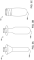
FIGS. 3A-3C are top perspective views of various examples of preforms employed for use in a blow molding process according to the method ofFIG. 1 ; and -
FIG. 4 is a bottom perspective view of a plastic container formed in a free blow molding process according to the method ofFIG. 1 . - The following detailed description and appended drawings describe and illustrate various exemplary embodiments of the invention. The description and drawings serve to enable one skilled in the art to make and use the invention, and are not intended to limit the scope of the invention in any manner. In respect of the methods disclosed, the steps presented are exemplary in nature, and thus, the order of the steps is not necessary or critical.
- "A" and "an" as used herein indicate "at least one" of the item is present; a plurality of such items may be present, when possible. As used herein, "substantially" means "to a considerable degree," "largely," or "proximately" as a person skilled in the art in view of the instant disclosure would understand the term.
- Although the terms first, second, third, etc. may be used herein to describe various elements, components, regions, layers and/or sections, these elements, components, regions, layers and/or sections should not be limited by these terms. These terms may be only used to distinguish one element, component, region, layer or section from another region, layer or section. Terms such as "first," "second," and other numerical terms when used herein do not imply a sequence or order unless clearly indicated by the context. Thus, a first element, component, region, layer or section discussed below could be termed a second element, component, region, layer or section without departing from the teachings of the example embodiments.
-
FIG. 1 shows a flow chart of amethod 10 of designing a container 100 (as shown inFIG. 2 ) according to an embodiment of the invention. Thecontainer 100 is a hollow receptacle configured to hold a product such as a fluid, for example. As used herein thecontainer 100 is a plastic container. However, it is understood a portion or an entirety of the steps can be employed to design containers formed from alternate materials such as glass or other materials as desired. - In a
first step 12 of themethod 10, a conceptual design of thecontainer 100 is produced or otherwise obtained. The conceptual design may be a handmade drawing or a computer generated drawing such as produced by a design tool such as the CAD software suite. However, it is understood other types of medium, software, or three-dimensional renderings now known or later developed can be employed as desired. Thecontainer 100 will include aesthetic and/or functional features. For example, while not shown, thecontainer 100 can include handles, grips, indentations, ripples, curvatures, dimples, other surface features, and the like, for example, as desired. The aesthetic and/or functional features of thecontainer 100 may vary according to an end use of thecontainer 100. - In a
second step 14 of themethod 10, specifications of thecontainer 100 are determined to create an overall sidewall profile. As used herein the sidewall profile, refers to, but is not limited to, the overall three-dimensional shape of thecontainer 100 which includes the overall dimensions of thecontainer 100. The overall dimensions of thecontainer 100 can include inner and outer widths, lengths, and heights, sidewall thicknesses, angles, radiuses of curvatures, and other similar criteria. The specifications can also include a desired weight of thecontainer 100 when empty and a desired inner or outer volume of thecontainer 100. In athird step 16 of themethod 10, a mold 102 (seeFIG. 2 ) is produced, acquired, or simulated using a computer simulation program based on the determined specifications. - As shown in
FIG. 2 , themold 102 is formed from at least two separable parts. As illustrated, themold 102 is in an open or separated position. When combined or in a closed or joining position, the two separable parts form acavity 104. Thecavity 104 corresponds in shape to a shape and a size of the resultingcontainer 100. - With renewed reference to
FIG. 1 , in afourth step 18 of themethod 10, a preform 106 (seeFIG. 3 for examples) is selected. As used herein, thepreform 106 also sometimes referred to as a parison, is used to refer to a term used in blow molding processes, injection blow molding processes, or injection stretch blow molding process. However, it is understood thepreform 106 can also be a term used in other processes such as extrusion blow molding or, for example. Thepreform 106 is formed from plastic and is a tube-like piece of plastic with a hole in one end through which fluid can pass. Thepreform 106 is then positioned within themold 102 and the fluid is blown into themold 102 to expand the plastic to match the contour of thecavity 104 of themold 102. Thepreform 106 selected is typically based on weight and axial and radial stretch ratios obtainable by thepreform 106 when reheated and blow molded to form thecontainer 100. Thepreform 106 may have any desired shape, radius, wall thickness, weight, length, and/or height. - Examples of various ones of the
preform 106 are shown inFIGS. 3A-3C . For example, thepreform 106a inFIG. 3A is configured as a bell shaped preform. In another example, thepreform 106b inFIG. 3B is configured as areverse draft preform 106b. In yet another example, thepreform 106c inFIG. 3C is a wide-mouthconical preform 106c. However, it is understood thepreform 106 can be configured as any preform now known or later developed with any sidewall profile, cross-sectional or three-dimensional shapes as desired. Thepreform 106 may be formed from any material, as desired, that meets the known objectives of the resultingcontainer 100. For example, suitable polymers from which thepreform 106 and thecontainer 100 may be formed include, but are not necessarily limited to, polyethylene terephthalate (PET) and other polyesters, polypropylene, acrylonitrile acid esters, vinyl chlorides, polyolefins, polyamides, and the like, as well as derivatives, blends, and copolymers thereof. - With renewed reference to
FIG. 1 , step 18 of themethod 10 is a preform selection step. Thepreform 106 is selected according to a comparison of the shape of the resultingcontainer 100 and a shape of a resulting container formed by a free blow molding or free blowing of a preform as described in more detail below.Step 20 of themethod 10 is free blowing thepreform 106. As shown, thestep 20 of free blowing the preform may occur as a part of thepreform selection step 18. However, in another embodiment thestep 20 of free blowing thepreform 106 may not be necessary as a part of thepreform selection step 18 as thefree blowing step 20 may have occurred prior to themethod 10. For example, prior to themethod 10, a profile of thepreform 106 which may include a table, a graph, a chart, a formula, a mathematical correlation, or other index or reference guide of the previously-determined information related to a resulting free blown container formed from a particular preform may be available for reference and comparison to thecontainer 100. The profile of thepreform 106 may also include a range of fluid volumes that the resulting free blown container may be capable of holding. As a result, a known preform already free blown into a free blown container may be employed. That is, the preformfree blowing step 20 may have occurred before thepreform selection step 18 or even the conceptual design of thecontainer step 12. - Free blowing of the
preform 106 is a process by which thepreform 106 is heated to equilibrium in an oven and then blow molded using liquid as a free blow medium, for example, without the use of a mold having a mold cavity. Thepreform 106 is allowed to take a shape as dictated by the pressure of the liquid, the volume of the liquid, the materials forming thepreform 106, gravity, the temperature of the oven, and other process and preform variables. - A free blown
container 108 resulting from the free blowing of thepreform 106 formed using a liquid blowing medium (not shown) is illustrated inFIG. 4 . The free blowncontainer 108, because it is formed without the use of a mold, has a tear-drop shape and a closedrounded bottom 110. The free blowncontainer 108 has a resulting sidewall profile. As noted above, various sidewall profiles of the free blowncontainer 108 formed with the same preforms under different conditions may be generated. For example, free blowing a first preform of a known material and known dimensions under first parameters, such as a first temperature of the oven and a first pressure the free blow fluid, may result in a container having a different sidewall profile than free blowing a second preform with the same material and dimensions as the first preform under second parameters, such as a second temperature of the oven and a second pressure of the free blow fluid. Changing the parameters under which the preform is free blown assists in determining the free blowncontainer 108 that has a similar sidewall profile as thecontainer 100 and may also assist in creating the profile for thepreform 106. - An acceptable one of the free blown
container 108 will be substantially free from surface defects, unacceptable wall thickness variations, and/or holes or punctures. Also, the free blowncontainer 108 will expand with a volume sufficient to contain a desired volume of a product therein. Additional profiles for thepreform 106 may be generated by free blowing different weight or shaped preforms formed from different materials, having different lengths, wall thicknesses, diameters, and/or other material or dimensional variations and under different process conditions, such as temperature, fluid volume, blowing medium pressure, and the like. As described herein above, each different preform free blown under the various conditions and parameters or having the various differences in properties described herein will result in a different free blown container having its own unique inner volume (ie volume of the cavity) for containing the product, lengths, widths, shapes, diameters, wall thicknesses, wall thickness profile, angles, radiuses of curvatures, and other desired dimensions. In this way, a reference guide of free blown containers may be generated with the specific sidewall profile of thepreform 106 used to form the free blowncontainer 108 and the specific condition under which thepreform 106 underwent to form the free blowncontainer 108. Particularly advantageous of a reference guide is the ability to relate particular preforms to their maximum inner volume capability. As a result, a preform can be chosen to form a free blowncontainer 108 that is capable of holding a desired volume of the product. - In
step 22 of thepreform selection step 18 of themethod 10, a comparison of thecontainer 100 and the free blowncontainer 108 is performed. For example, a sidewall profile, shape, or outer contour of the free blowncontainer 108 is compared to a shape or inner contour of thecavity 104 of themold 102 or a sidewall profile, a shape or outer contour of thecontainer 100. A difference between the sidewall profile of the free blowncontainer 108 and thecontainer 100 can be determined and minimized. The comparison of the free blowncontainer 108 and thecavity 104 and/or thecontainer 100 may happen physically by placing the free blowncontainer 108 in or next to thecavity 104 of themold 102 or thecontainer 100, a design drawing of themold 102 or thecontainer 100, or the like. Additionally, the comparison may occur with the assistance of a computer modeling tool or spreadsheet, for example, wherein thecavity 104 of themold 102 or thecontainer 100 and the free blowncontainer 108 specifications are entered therein and a difference therebetween can be computed. - In the
comparison step 22, as the void space of thecavity 104 occupied by the free blowncontainer 108 increases, the more likely thecontainer 100 formed from thepreform 106 that resulted in the free blowncontainer 108 is to result in thecontainer 100 having an acceptable appearance and acceptable performance capabilities. Similarly, if the free blowncontainer 108 is compared to thecontainer 100, as differences between the sidewall profiles, outer contours, and dimensions of the free blowncontainer 108 and thecontainer 100 are minimized, the more likely thecontainer 100 formed from thepreform 106 that resulted in the free blowncontainer 108 is to result in thecontainer 100 having an acceptable appearance and acceptable performance capabilities. The free blowncontainer 108 may have dimensions larger than thecontainer 100 wherein certain areas of the sidewall profile or the contour of the free blowncontainer 108 may extend over the profile or the contour of thecontainer 100, or the profile or the contour of thecontainer 100 may extend over the free blowncontainer 108. However, the end goal is to minimize such differences regardless which one of thecontainers - To minimize the differences, a preform different from the prior compared preform with different dimensions or parameters may be selected from the profiles made as referenced herein above, or a different preform may be free blown in the
free blow step 20 and thecomparison step 22 repeated. Alternatively, thefree blow step 20 may be performed under different process conditions but with thesame preform 106 prior to thecomparison step 22. In this way, only thefree blow step 20 is repeated, and thefree blow step 20 is relatively quick and easy to perform as no mold or mold design is required. Thefree blow step 20 could initially involve the free blow molding of numerous and different preforms under numerous and different process conditions. - While numerous preforms and free blown containers selected from the reference guide of free blown containers may result in a container that is acceptable in its performance and aesthetics, minimizing the difference between the free blown
container 108 and thecavity 104 or thecontainer 100 itself will result in an optimized distribution of material forming thepreform 106. Thus, the distribution of material of thecontainer 100 is optimized resulting in minimal surface defects and a reduction in material costs and militates against over-engineering of thecontainer 100. - Once the desired free blown
container 108 design has been determined according to the methods described herein, thepreform 106 used to form the desired free blowncontainer 108 under the known conditions (e.g., temperature, fluid pressure, etc.) may be used to manufacture thecontainer 100 in astep 24. Thecontainer 100 may be manufactured in either a small batch test or full-scale manufacturing under the conditions and parameters resulting with the free blowncontainer 108 that most optimally overlapped with thecontainer 100 in thecomparison step 22 of thepreform selection step 18. - The free blown
container 108 is obtained using liquid as the free blow medium. Once obtained, the free blowncontainer 108 may be considered as verification that a particular container shape, volume, weight, dimensions and the like may be obtained using thepreform 106, regardless of the blowing medium used to form thecontainer 100. For example, once a particular container sidewall profile, shape, volume, weight, dimensions and the like obtainable using thepreform 106 is verified by creating the free blowncontainer 108 using liquid as the blowing medium, a design of thecontainer 100 may be created that is based on the free blowncontainer 108. Thecontainer 100 may then be mass produced from thepreform 106 using air as a blowing medium, because the free blowncontainer 108 provides verification that thepreform 106 may be formed into the desiredcontainer 100 using other container forming processes. In this way, a designer may design thecontainer 100 by first considering the characteristics of thepreform 106, rather than iteratively designing thepreform 106 to obtain the desired sidewall profile of thecontainer 100. - By utilizing the methods of the instant invention, design of plastic containers becomes less iterative and based more on quantifiable and known parameters rather than a "guess-and-check" methodology. While known plastic container design methods involve creating a container and testing preforms to determine whether and how such a preform or process condition may be modified to result in a desired container, the present invention involves a method of creating a container and determining an acceptable preform to form the container based on how such a preform performs when free blown under known process conditions. The method of the instant invention is thus non-iterative in nature, and the time and cost to take a container from concept to manufacturing is minimized. Specifically, the time is reduced from months or weeks to days.
Claims (9)
- A method (10) of designing a plastic container (100) comprising the steps of:providing (12) a design of a container (100) having a first sidewall profile, wherein the first sidewall profile corresponds to a first volume of liquid being contained within the container (100);free blow molding (20) a first preform (106) having known dimensions to result in a free blown container (108) having a second sidewall profile, wherein the free blow molding is performed using liquid as the free blow medium;comparing (22) the first sidewall profile of the design of the container (100) to the second sidewall profile of the free blown container (108); andrepeating the free blow molding step using a second preform with different known dimensions or under different free blow molding conditions from the first preform to minimize a difference between the first sidewall profile of the design of the container (100) and the second sidewall profile of the free blown container, wherein repeating the free blow molding step further includes verifying that the second sidewall profile of the free blown container (108) corresponds to the free blown container containing the first volume of liquid therein, and wherein the second preform with different known dimensions or the different free blow molding conditions are selected based on a reference guide of previously-determined information related to a resulting free blown container formed from a particular preform.
- The method (10) of Claim 1, further comprising the step of determining (14) specifications for the design of the container (100).
- The method (10) of Claim 2, further comprising the step of providing (16) a mold (102) based on the specifications for the design of the container (100).
- The method (10) of Claim 1, wherein a profile of dimensions and free blow molding conditions of preforms is created for reference from data acquired from the free blow molding step and repeating the free blow molding step.
- The method (10) of Claim 1, further comprising the step of selecting one of the first preform (106) and the second preform, the second sidewall profile of the free blown container (108) formed from the selected one of the first preform and the second preform having less differences from the first sidewall profile of the design of the container (100) than the differences between the second sidewall profile of free blown container (108) formed from the other one of the first preform and the second preform and the first sidewall profile of the design of the container (100).
- The method (10) of Claim 5, wherein a preform sidewall profile and a free blow molding condition of the selected one of the first preform (106) and the second preform are used to select a preform for forming the container (100) in a mold (102).
- The method (10) of Claim 6, wherein the preform sidewall profile and the free blow molding condition of the selected one of the first preform (106) and the second preform are used to select a plurality of preforms for forming a plurality of the containers in a manufacturing process.
- The method (10) of Claim 3, wherein the specifications include at least one of: the dimensions of the container (100) and a weight of the container (100) when empty.
- The method (10) of Claim 1, wherein the different free blow molding conditions include a temperature of an oven and a pressure of a fluid blowing medium used to form a respective one of the preforms.
Applications Claiming Priority (2)
| Application Number | Priority Date | Filing Date | Title |
|---|---|---|---|
| US201862691670P | 2018-06-29 | 2018-06-29 | |
| PCT/IB2019/000800 WO2020002993A1 (en) | 2018-06-29 | 2019-06-24 | Free blow bottle design |
Publications (2)
| Publication Number | Publication Date |
|---|---|
| EP3814093A1 EP3814093A1 (en) | 2021-05-05 |
| EP3814093B1 true EP3814093B1 (en) | 2024-02-07 |
Family
ID=68242751
Family Applications (1)
| Application Number | Title | Priority Date | Filing Date |
|---|---|---|---|
| EP19787404.3A Active EP3814093B1 (en) | 2018-06-29 | 2019-06-24 | Free blow bottle design |
Country Status (4)
| Country | Link |
|---|---|
| US (1) | US11639020B2 (en) |
| EP (1) | EP3814093B1 (en) |
| CN (1) | CN112351874A (en) |
| WO (1) | WO2020002993A1 (en) |
Citations (1)
| Publication number | Priority date | Publication date | Assignee | Title |
|---|---|---|---|---|
| CN103097110A (en) * | 2010-09-20 | 2013-05-08 | 西德尔合作公司 | Process for forming a container by selective laser heating and free blowing |
Family Cites Families (7)
| Publication number | Priority date | Publication date | Assignee | Title |
|---|---|---|---|---|
| JPH0740955A (en) | 1993-07-28 | 1995-02-10 | Toyo Seikan Kaisha Ltd | Method and apparatus for manufacturing biaxially stretched plastic bottle having excellent heat resistance |
| JP2876992B2 (en) | 1994-06-21 | 1999-03-31 | 東洋製罐株式会社 | Manufacturing method of biaxially stretched blow container |
| US6230547B1 (en) * | 1997-12-05 | 2001-05-15 | Eastman Chemical Company | Technique for free-blowing plastic preforms |
| CN1455729A (en) | 2001-02-06 | 2003-11-12 | 花王株式会社 | Method and device for design of preform |
| FR2848906B1 (en) * | 2002-12-23 | 2006-08-18 | Sidel Sa | METHOD AND INSTALLATION FOR MANUFACTURING A CONTAINER OF PLASTIC MATERIAL |
| JP6169171B2 (en) | 2012-06-27 | 2017-07-26 | ディスクマ アーゲーDiscma Ag | Method and apparatus for the manufacture of containers such as beverage containers |
| EP2883680A1 (en) | 2013-12-16 | 2015-06-17 | Discma AG | A method and apparatus for fabricating containers |
-
2019
- 2019-06-24 CN CN201980043399.2A patent/CN112351874A/en active Pending
- 2019-06-24 WO PCT/IB2019/000800 patent/WO2020002993A1/en not_active Ceased
- 2019-06-24 US US17/254,966 patent/US11639020B2/en active Active
- 2019-06-24 EP EP19787404.3A patent/EP3814093B1/en active Active
Patent Citations (1)
| Publication number | Priority date | Publication date | Assignee | Title |
|---|---|---|---|---|
| CN103097110A (en) * | 2010-09-20 | 2013-05-08 | 西德尔合作公司 | Process for forming a container by selective laser heating and free blowing |
Also Published As
| Publication number | Publication date |
|---|---|
| WO2020002993A1 (en) | 2020-01-02 |
| US11639020B2 (en) | 2023-05-02 |
| CN112351874A (en) | 2021-02-09 |
| US20210162648A1 (en) | 2021-06-03 |
| EP3814093A1 (en) | 2021-05-05 |
Similar Documents
| Publication | Publication Date | Title |
|---|---|---|
| JP2011506132A5 (en) | ||
| JP5714909B2 (en) | Blow molded liner for overpack container and method for producing the same | |
| EP2722107B1 (en) | Apparatus and method providing blow nozzle to control liquid flow | |
| AU2011316513B2 (en) | Blow nozzle to control liquid flow with pre-stretch rod assembly | |
| McEvoy et al. | Simulation of the stretch blow molding process of PET bottles | |
| CN110785277A (en) | Method of molding container having surface markings and container | |
| CN103201179A (en) | A blow molded container | |
| EP2780146B9 (en) | Plural blow utilization of counter stretch rod and/or base pushup | |
| US11639020B2 (en) | Free blow bottle design | |
| JP2021504196A (en) | Systems and methods for forming stretch blow molded pipettes and stretch blow molded pipettes | |
| Saini et al. | A computer simulation and experimental study of weight reduced carbonated soft drink PET bottle manufacturing | |
| EP2800660B1 (en) | Molding method and apparatus for applying positive pressure to molded container | |
| MX2013005278A (en) | A PROCESS FOR THE MANUFACTURE OF A CONTAINER AND A CONTAINER. | |
| AU2025217307A1 (en) | Methods for digitally designing preforms and molding instructions for bottles | |
| JP2002326220A (en) | Manufacturing method of two-layer preform | |
| Demirel et al. | Experimental study of preform reheat temperature in two‐stage injection stretch blow molding | |
| US20070045221A1 (en) | Plastic container having a ring-shaped reinforcement and method of making same | |
| CN117580701A (en) | Thermal Imaging Methods for Blow Molding Methods | |
| Suvanjumrat et al. | [RETRACTED ARTICLE] Blow Molding Simulation using Cross-Section Technique for Complex Shape Bottles | |
| JP2010513157A (en) | Container filling method, process for manufacturing containers, and manufactured containers | |
| WO1999030150A1 (en) | Technique for free-blowing plastic preforms | |
| CN109204992A (en) | Prefabricated component for blow molding operation | |
| Bin Shuaib et al. | Rheological Study of property variation of virgin polymer with the introduction of recycled content during polymer processing A parametric analysis | |
| Suvanjumrat et al. | A novel simulation of bottle blow molding to determine suitable parison thicknesses for die shaping. | |
| CN115702074B (en) | Method for forming a container with a suspension device |
Legal Events
| Date | Code | Title | Description |
|---|---|---|---|
| STAA | Information on the status of an ep patent application or granted ep patent |
Free format text: STATUS: UNKNOWN |
|
| STAA | Information on the status of an ep patent application or granted ep patent |
Free format text: STATUS: THE INTERNATIONAL PUBLICATION HAS BEEN MADE |
|
| PUAI | Public reference made under article 153(3) epc to a published international application that has entered the european phase |
Free format text: ORIGINAL CODE: 0009012 |
|
| STAA | Information on the status of an ep patent application or granted ep patent |
Free format text: STATUS: REQUEST FOR EXAMINATION WAS MADE |
|
| 17P | Request for examination filed |
Effective date: 20201023 |
|
| AK | Designated contracting states |
Kind code of ref document: A1 Designated state(s): AL AT BE BG CH CY CZ DE DK EE ES FI FR GB GR HR HU IE IS IT LI LT LU LV MC MK MT NL NO PL PT RO RS SE SI SK SM TR |
|
| DAV | Request for validation of the european patent (deleted) | ||
| DAX | Request for extension of the european patent (deleted) | ||
| STAA | Information on the status of an ep patent application or granted ep patent |
Free format text: STATUS: EXAMINATION IS IN PROGRESS |
|
| 17Q | First examination report despatched |
Effective date: 20221114 |
|
| P01 | Opt-out of the competence of the unified patent court (upc) registered |
Effective date: 20230419 |
|
| REG | Reference to a national code |
Ref legal event code: R079 Free format text: PREVIOUS MAIN CLASS: B29C0049020000 Ipc: B29C0049420000 Ref country code: DE Ref document number: 602019046221 Country of ref document: DE |
|
| GRAP | Despatch of communication of intention to grant a patent |
Free format text: ORIGINAL CODE: EPIDOSNIGR1 |
|
| STAA | Information on the status of an ep patent application or granted ep patent |
Free format text: STATUS: GRANT OF PATENT IS INTENDED |
|
| RIC1 | Information provided on ipc code assigned before grant |
Ipc: B29C 49/78 20060101ALN20231006BHEP Ipc: B29C 49/06 20060101ALN20231006BHEP Ipc: B29C 49/04 20060101ALN20231006BHEP Ipc: B29C 49/02 20060101ALI20231006BHEP Ipc: B29C 49/42 20060101AFI20231006BHEP |
|
| INTG | Intention to grant announced |
Effective date: 20231024 |
|
| GRAS | Grant fee paid |
Free format text: ORIGINAL CODE: EPIDOSNIGR3 |
|
| GRAA | (expected) grant |
Free format text: ORIGINAL CODE: 0009210 |
|
| STAA | Information on the status of an ep patent application or granted ep patent |
Free format text: STATUS: THE PATENT HAS BEEN GRANTED |
|
| AK | Designated contracting states |
Kind code of ref document: B1 Designated state(s): AL AT BE BG CH CY CZ DE DK EE ES FI FR GB GR HR HU IE IS IT LI LT LU LV MC MK MT NL NO PL PT RO RS SE SI SK SM TR |
|
| REG | Reference to a national code |
Ref country code: GB Ref legal event code: FG4D |
|
| REG | Reference to a national code |
Ref country code: CH Ref legal event code: EP |
|
| REG | Reference to a national code |
Ref country code: IE Ref legal event code: FG4D |
|
| REG | Reference to a national code |
Ref country code: DE Ref legal event code: R096 Ref document number: 602019046221 Country of ref document: DE |
|
| REG | Reference to a national code |
Ref country code: LT Ref legal event code: MG9D |
|
| REG | Reference to a national code |
Ref country code: NL Ref legal event code: MP Effective date: 20240207 |
|
| PG25 | Lapsed in a contracting state [announced via postgrant information from national office to epo] |
Ref country code: IS Free format text: LAPSE BECAUSE OF FAILURE TO SUBMIT A TRANSLATION OF THE DESCRIPTION OR TO PAY THE FEE WITHIN THE PRESCRIBED TIME-LIMIT Effective date: 20240607 |
|
| PG25 | Lapsed in a contracting state [announced via postgrant information from national office to epo] |
Ref country code: LT Free format text: LAPSE BECAUSE OF FAILURE TO SUBMIT A TRANSLATION OF THE DESCRIPTION OR TO PAY THE FEE WITHIN THE PRESCRIBED TIME-LIMIT Effective date: 20240207 |
|
| PG25 | Lapsed in a contracting state [announced via postgrant information from national office to epo] |
Ref country code: GR Free format text: LAPSE BECAUSE OF FAILURE TO SUBMIT A TRANSLATION OF THE DESCRIPTION OR TO PAY THE FEE WITHIN THE PRESCRIBED TIME-LIMIT Effective date: 20240508 |
|
| REG | Reference to a national code |
Ref country code: AT Ref legal event code: MK05 Ref document number: 1655096 Country of ref document: AT Kind code of ref document: T Effective date: 20240207 |
|
| PG25 | Lapsed in a contracting state [announced via postgrant information from national office to epo] |
Ref country code: NL Free format text: LAPSE BECAUSE OF FAILURE TO SUBMIT A TRANSLATION OF THE DESCRIPTION OR TO PAY THE FEE WITHIN THE PRESCRIBED TIME-LIMIT Effective date: 20240207 Ref country code: HR Free format text: LAPSE BECAUSE OF FAILURE TO SUBMIT A TRANSLATION OF THE DESCRIPTION OR TO PAY THE FEE WITHIN THE PRESCRIBED TIME-LIMIT Effective date: 20240207 Ref country code: RS Free format text: LAPSE BECAUSE OF FAILURE TO SUBMIT A TRANSLATION OF THE DESCRIPTION OR TO PAY THE FEE WITHIN THE PRESCRIBED TIME-LIMIT Effective date: 20240507 |
|
| PG25 | Lapsed in a contracting state [announced via postgrant information from national office to epo] |
Ref country code: ES Free format text: LAPSE BECAUSE OF FAILURE TO SUBMIT A TRANSLATION OF THE DESCRIPTION OR TO PAY THE FEE WITHIN THE PRESCRIBED TIME-LIMIT Effective date: 20240207 |
|
| PG25 | Lapsed in a contracting state [announced via postgrant information from national office to epo] |
Ref country code: AT Free format text: LAPSE BECAUSE OF FAILURE TO SUBMIT A TRANSLATION OF THE DESCRIPTION OR TO PAY THE FEE WITHIN THE PRESCRIBED TIME-LIMIT Effective date: 20240207 |
|
| PG25 | Lapsed in a contracting state [announced via postgrant information from national office to epo] |
Ref country code: RS Free format text: LAPSE BECAUSE OF FAILURE TO SUBMIT A TRANSLATION OF THE DESCRIPTION OR TO PAY THE FEE WITHIN THE PRESCRIBED TIME-LIMIT Effective date: 20240507 Ref country code: NO Free format text: LAPSE BECAUSE OF FAILURE TO SUBMIT A TRANSLATION OF THE DESCRIPTION OR TO PAY THE FEE WITHIN THE PRESCRIBED TIME-LIMIT Effective date: 20240507 Ref country code: NL Free format text: LAPSE BECAUSE OF FAILURE TO SUBMIT A TRANSLATION OF THE DESCRIPTION OR TO PAY THE FEE WITHIN THE PRESCRIBED TIME-LIMIT Effective date: 20240207 Ref country code: LT Free format text: LAPSE BECAUSE OF FAILURE TO SUBMIT A TRANSLATION OF THE DESCRIPTION OR TO PAY THE FEE WITHIN THE PRESCRIBED TIME-LIMIT Effective date: 20240207 Ref country code: IS Free format text: LAPSE BECAUSE OF FAILURE TO SUBMIT A TRANSLATION OF THE DESCRIPTION OR TO PAY THE FEE WITHIN THE PRESCRIBED TIME-LIMIT Effective date: 20240607 Ref country code: HR Free format text: LAPSE BECAUSE OF FAILURE TO SUBMIT A TRANSLATION OF THE DESCRIPTION OR TO PAY THE FEE WITHIN THE PRESCRIBED TIME-LIMIT Effective date: 20240207 Ref country code: GR Free format text: LAPSE BECAUSE OF FAILURE TO SUBMIT A TRANSLATION OF THE DESCRIPTION OR TO PAY THE FEE WITHIN THE PRESCRIBED TIME-LIMIT Effective date: 20240508 Ref country code: FI Free format text: LAPSE BECAUSE OF FAILURE TO SUBMIT A TRANSLATION OF THE DESCRIPTION OR TO PAY THE FEE WITHIN THE PRESCRIBED TIME-LIMIT Effective date: 20240207 Ref country code: ES Free format text: LAPSE BECAUSE OF FAILURE TO SUBMIT A TRANSLATION OF THE DESCRIPTION OR TO PAY THE FEE WITHIN THE PRESCRIBED TIME-LIMIT Effective date: 20240207 Ref country code: BG Free format text: LAPSE BECAUSE OF FAILURE TO SUBMIT A TRANSLATION OF THE DESCRIPTION OR TO PAY THE FEE WITHIN THE PRESCRIBED TIME-LIMIT Effective date: 20240207 Ref country code: AT Free format text: LAPSE BECAUSE OF FAILURE TO SUBMIT A TRANSLATION OF THE DESCRIPTION OR TO PAY THE FEE WITHIN THE PRESCRIBED TIME-LIMIT Effective date: 20240207 |
|
| PG25 | Lapsed in a contracting state [announced via postgrant information from national office to epo] |
Ref country code: PL Free format text: LAPSE BECAUSE OF FAILURE TO SUBMIT A TRANSLATION OF THE DESCRIPTION OR TO PAY THE FEE WITHIN THE PRESCRIBED TIME-LIMIT Effective date: 20240207 Ref country code: PT Free format text: LAPSE BECAUSE OF FAILURE TO SUBMIT A TRANSLATION OF THE DESCRIPTION OR TO PAY THE FEE WITHIN THE PRESCRIBED TIME-LIMIT Effective date: 20240607 |
|
| PG25 | Lapsed in a contracting state [announced via postgrant information from national office to epo] |
Ref country code: SE Free format text: LAPSE BECAUSE OF FAILURE TO SUBMIT A TRANSLATION OF THE DESCRIPTION OR TO PAY THE FEE WITHIN THE PRESCRIBED TIME-LIMIT Effective date: 20240207 Ref country code: PT Free format text: LAPSE BECAUSE OF FAILURE TO SUBMIT A TRANSLATION OF THE DESCRIPTION OR TO PAY THE FEE WITHIN THE PRESCRIBED TIME-LIMIT Effective date: 20240607 Ref country code: PL Free format text: LAPSE BECAUSE OF FAILURE TO SUBMIT A TRANSLATION OF THE DESCRIPTION OR TO PAY THE FEE WITHIN THE PRESCRIBED TIME-LIMIT Effective date: 20240207 Ref country code: LV Free format text: LAPSE BECAUSE OF FAILURE TO SUBMIT A TRANSLATION OF THE DESCRIPTION OR TO PAY THE FEE WITHIN THE PRESCRIBED TIME-LIMIT Effective date: 20240207 |
|
| PG25 | Lapsed in a contracting state [announced via postgrant information from national office to epo] |
Ref country code: DK Free format text: LAPSE BECAUSE OF FAILURE TO SUBMIT A TRANSLATION OF THE DESCRIPTION OR TO PAY THE FEE WITHIN THE PRESCRIBED TIME-LIMIT Effective date: 20240207 |
|
| PG25 | Lapsed in a contracting state [announced via postgrant information from national office to epo] |
Ref country code: SM Free format text: LAPSE BECAUSE OF FAILURE TO SUBMIT A TRANSLATION OF THE DESCRIPTION OR TO PAY THE FEE WITHIN THE PRESCRIBED TIME-LIMIT Effective date: 20240207 |
|
| PG25 | Lapsed in a contracting state [announced via postgrant information from national office to epo] |
Ref country code: EE Free format text: LAPSE BECAUSE OF FAILURE TO SUBMIT A TRANSLATION OF THE DESCRIPTION OR TO PAY THE FEE WITHIN THE PRESCRIBED TIME-LIMIT Effective date: 20240207 Ref country code: CZ Free format text: LAPSE BECAUSE OF FAILURE TO SUBMIT A TRANSLATION OF THE DESCRIPTION OR TO PAY THE FEE WITHIN THE PRESCRIBED TIME-LIMIT Effective date: 20240207 |
|
| PG25 | Lapsed in a contracting state [announced via postgrant information from national office to epo] |
Ref country code: SK Free format text: LAPSE BECAUSE OF FAILURE TO SUBMIT A TRANSLATION OF THE DESCRIPTION OR TO PAY THE FEE WITHIN THE PRESCRIBED TIME-LIMIT Effective date: 20240207 |
|
| PG25 | Lapsed in a contracting state [announced via postgrant information from national office to epo] |
Ref country code: SM Free format text: LAPSE BECAUSE OF FAILURE TO SUBMIT A TRANSLATION OF THE DESCRIPTION OR TO PAY THE FEE WITHIN THE PRESCRIBED TIME-LIMIT Effective date: 20240207 Ref country code: SK Free format text: LAPSE BECAUSE OF FAILURE TO SUBMIT A TRANSLATION OF THE DESCRIPTION OR TO PAY THE FEE WITHIN THE PRESCRIBED TIME-LIMIT Effective date: 20240207 Ref country code: RO Free format text: LAPSE BECAUSE OF FAILURE TO SUBMIT A TRANSLATION OF THE DESCRIPTION OR TO PAY THE FEE WITHIN THE PRESCRIBED TIME-LIMIT Effective date: 20240207 Ref country code: EE Free format text: LAPSE BECAUSE OF FAILURE TO SUBMIT A TRANSLATION OF THE DESCRIPTION OR TO PAY THE FEE WITHIN THE PRESCRIBED TIME-LIMIT Effective date: 20240207 Ref country code: DK Free format text: LAPSE BECAUSE OF FAILURE TO SUBMIT A TRANSLATION OF THE DESCRIPTION OR TO PAY THE FEE WITHIN THE PRESCRIBED TIME-LIMIT Effective date: 20240207 Ref country code: CZ Free format text: LAPSE BECAUSE OF FAILURE TO SUBMIT A TRANSLATION OF THE DESCRIPTION OR TO PAY THE FEE WITHIN THE PRESCRIBED TIME-LIMIT Effective date: 20240207 |
|
| REG | Reference to a national code |
Ref country code: DE Ref legal event code: R097 Ref document number: 602019046221 Country of ref document: DE |
|
| PLBE | No opposition filed within time limit |
Free format text: ORIGINAL CODE: 0009261 |
|
| STAA | Information on the status of an ep patent application or granted ep patent |
Free format text: STATUS: NO OPPOSITION FILED WITHIN TIME LIMIT |
|
| 26N | No opposition filed |
Effective date: 20241108 |
|
| PG25 | Lapsed in a contracting state [announced via postgrant information from national office to epo] |
Ref country code: MC Free format text: LAPSE BECAUSE OF FAILURE TO SUBMIT A TRANSLATION OF THE DESCRIPTION OR TO PAY THE FEE WITHIN THE PRESCRIBED TIME-LIMIT Effective date: 20240207 |
|
| PG25 | Lapsed in a contracting state [announced via postgrant information from national office to epo] |
Ref country code: LU Free format text: LAPSE BECAUSE OF NON-PAYMENT OF DUE FEES Effective date: 20240624 |
|
| GBPC | Gb: european patent ceased through non-payment of renewal fee |
Effective date: 20240624 |
|
| PG25 | Lapsed in a contracting state [announced via postgrant information from national office to epo] |
Ref country code: IE Free format text: LAPSE BECAUSE OF NON-PAYMENT OF DUE FEES Effective date: 20240624 |
|
| PG25 | Lapsed in a contracting state [announced via postgrant information from national office to epo] |
Ref country code: BE Free format text: LAPSE BECAUSE OF NON-PAYMENT OF DUE FEES Effective date: 20240630 Ref country code: SI Free format text: LAPSE BECAUSE OF FAILURE TO SUBMIT A TRANSLATION OF THE DESCRIPTION OR TO PAY THE FEE WITHIN THE PRESCRIBED TIME-LIMIT Effective date: 20240207 |
|
| PG25 | Lapsed in a contracting state [announced via postgrant information from national office to epo] |
Ref country code: GB Free format text: LAPSE BECAUSE OF NON-PAYMENT OF DUE FEES Effective date: 20240624 |
|
| REG | Reference to a national code |
Ref country code: BE Ref legal event code: MM Effective date: 20240630 |
|
| PGFP | Annual fee paid to national office [announced via postgrant information from national office to epo] |
Ref country code: DE Payment date: 20250528 Year of fee payment: 7 |
|
| PGFP | Annual fee paid to national office [announced via postgrant information from national office to epo] |
Ref country code: IT Payment date: 20250528 Year of fee payment: 7 |
|
| PGFP | Annual fee paid to national office [announced via postgrant information from national office to epo] |
Ref country code: FR Payment date: 20250610 Year of fee payment: 7 |
|
| PGFP | Annual fee paid to national office [announced via postgrant information from national office to epo] |
Ref country code: CH Payment date: 20250701 Year of fee payment: 7 |
|
| PG25 | Lapsed in a contracting state [announced via postgrant information from national office to epo] |
Ref country code: CY Free format text: LAPSE BECAUSE OF FAILURE TO SUBMIT A TRANSLATION OF THE DESCRIPTION OR TO PAY THE FEE WITHIN THE PRESCRIBED TIME-LIMIT; INVALID AB INITIO Effective date: 20190624 |
|
| PG25 | Lapsed in a contracting state [announced via postgrant information from national office to epo] |
Ref country code: HU Free format text: LAPSE BECAUSE OF FAILURE TO SUBMIT A TRANSLATION OF THE DESCRIPTION OR TO PAY THE FEE WITHIN THE PRESCRIBED TIME-LIMIT; INVALID AB INITIO Effective date: 20190624 |
|
| PG25 | Lapsed in a contracting state [announced via postgrant information from national office to epo] |
Ref country code: TR Free format text: LAPSE BECAUSE OF FAILURE TO SUBMIT A TRANSLATION OF THE DESCRIPTION OR TO PAY THE FEE WITHIN THE PRESCRIBED TIME-LIMIT Effective date: 20240207 |