EP3813591B1 - Rack system - Google Patents
Rack system Download PDFInfo
- Publication number
- EP3813591B1 EP3813591B1 EP19737919.1A EP19737919A EP3813591B1 EP 3813591 B1 EP3813591 B1 EP 3813591B1 EP 19737919 A EP19737919 A EP 19737919A EP 3813591 B1 EP3813591 B1 EP 3813591B1
- Authority
- EP
- European Patent Office
- Prior art keywords
- support bracket
- bracket
- support
- engaging
- locking
- Prior art date
- Legal status (The legal status is an assumption and is not a legal conclusion. Google has not performed a legal analysis and makes no representation as to the accuracy of the status listed.)
- Active
Links
Images





Classifications
-
- A—HUMAN NECESSITIES
- A47—FURNITURE; DOMESTIC ARTICLES OR APPLIANCES; COFFEE MILLS; SPICE MILLS; SUCTION CLEANERS IN GENERAL
- A47B—TABLES; DESKS; OFFICE FURNITURE; CABINETS; DRAWERS; GENERAL DETAILS OF FURNITURE
- A47B57/00—Cabinets, racks or shelf units, characterised by features for adjusting shelves or partitions
- A47B57/30—Cabinets, racks or shelf units, characterised by features for adjusting shelves or partitions with means for adjusting the height of detachable shelf supports
- A47B57/32—Cabinets, racks or shelf units, characterised by features for adjusting shelves or partitions with means for adjusting the height of detachable shelf supports consisting of grooved or notched ledges, uprights or side walls
-
- A—HUMAN NECESSITIES
- A47—FURNITURE; DOMESTIC ARTICLES OR APPLIANCES; COFFEE MILLS; SPICE MILLS; SUCTION CLEANERS IN GENERAL
- A47B—TABLES; DESKS; OFFICE FURNITURE; CABINETS; DRAWERS; GENERAL DETAILS OF FURNITURE
- A47B57/00—Cabinets, racks or shelf units, characterised by features for adjusting shelves or partitions
- A47B57/30—Cabinets, racks or shelf units, characterised by features for adjusting shelves or partitions with means for adjusting the height of detachable shelf supports
- A47B57/40—Cabinets, racks or shelf units, characterised by features for adjusting shelves or partitions with means for adjusting the height of detachable shelf supports consisting of hooks coacting with openings
-
- A—HUMAN NECESSITIES
- A47—FURNITURE; DOMESTIC ARTICLES OR APPLIANCES; COFFEE MILLS; SPICE MILLS; SUCTION CLEANERS IN GENERAL
- A47B—TABLES; DESKS; OFFICE FURNITURE; CABINETS; DRAWERS; GENERAL DETAILS OF FURNITURE
- A47B57/00—Cabinets, racks or shelf units, characterised by features for adjusting shelves or partitions
- A47B57/30—Cabinets, racks or shelf units, characterised by features for adjusting shelves or partitions with means for adjusting the height of detachable shelf supports
- A47B57/40—Cabinets, racks or shelf units, characterised by features for adjusting shelves or partitions with means for adjusting the height of detachable shelf supports consisting of hooks coacting with openings
- A47B57/408—Cabinets, racks or shelf units, characterised by features for adjusting shelves or partitions with means for adjusting the height of detachable shelf supports consisting of hooks coacting with openings with a security device
-
- A—HUMAN NECESSITIES
- A47—FURNITURE; DOMESTIC ARTICLES OR APPLIANCES; COFFEE MILLS; SPICE MILLS; SUCTION CLEANERS IN GENERAL
- A47B—TABLES; DESKS; OFFICE FURNITURE; CABINETS; DRAWERS; GENERAL DETAILS OF FURNITURE
- A47B96/00—Details of cabinets, racks or shelf units not covered by a single one of groups A47B43/00 - A47B95/00; General details of furniture
- A47B96/06—Brackets or similar supporting means for cabinets, racks or shelves
- A47B96/061—Cantilever brackets
-
- A—HUMAN NECESSITIES
- A47—FURNITURE; DOMESTIC ARTICLES OR APPLIANCES; COFFEE MILLS; SPICE MILLS; SUCTION CLEANERS IN GENERAL
- A47B—TABLES; DESKS; OFFICE FURNITURE; CABINETS; DRAWERS; GENERAL DETAILS OF FURNITURE
- A47B2200/00—General construction of tables or desks
- A47B2200/0035—Tables or desks with features relating to adjustability or folding
- A47B2200/0036—Table tops pivotable around longitudinal axis
-
- A—HUMAN NECESSITIES
- A47—FURNITURE; DOMESTIC ARTICLES OR APPLIANCES; COFFEE MILLS; SPICE MILLS; SUCTION CLEANERS IN GENERAL
- A47B—TABLES; DESKS; OFFICE FURNITURE; CABINETS; DRAWERS; GENERAL DETAILS OF FURNITURE
- A47B96/00—Details of cabinets, racks or shelf units not covered by a single one of groups A47B43/00 - A47B95/00; General details of furniture
- A47B96/06—Brackets or similar supporting means for cabinets, racks or shelves
- A47B96/07—Brackets or similar supporting means for cabinets, racks or shelves adjustable in themselves
Definitions
- the present disclosure concerns rack systems.
- US 5,022,621 is directed to a multi-hooks bracket adapted to hookably attach into vertically spaced and vertically elongated apertures of a multi-apertured column whereby the hookably attached bracket is adapted to cantileverly support office equipment, an improved multi-hooks bracket structure that is resistant to upward dislodgement from the multi-apertured column, said improved bracket structure comprising: (A) a generally horizontally extending arm having a periphery comprising a substantially horizontally upper-edge adapted to support office equipment thereat and also comprising an upright rear-side; (B) a plurality of vertically spaced hooks arrayed along an upright first-plane, each hook extending horizontally rearwardly and then downwardly from the arm rear-side whereby each hook is adapted to extend into and partially occupy the height of a vertically elongate aperture of a said multi-apertured column; and (C) a horizontally elongate lock located along said first-plane and at the arm rear
- US 5,185,971 discloses a channel adapted to fit within a slotted wall panel, comprising an elongated extruded member, which, in cross section, including: (a) a substantially U-shaped central box member, comprising a face plate adapted to be exposed on and oriented substantially parallel to an exposed surface of the panel, and two box support members extending substantially perpendicular from the face plate, adapted to extend into the panel from the face plate; (b) a flange member extending from each of the support members, comprising a flange plate connected to one of the support members and extending substantially parallel to the face plate, and a flange support member connected to the flange plate and extending substantially perpendicular to the flange plate, the two box support members and the flange support members being oriented substantially parallel to each other, and terminating in substantially the same plane.
- US 5,538,213 discloses a support bracket for shelving comprising a main body having a vertical edge from which extend a plurality of spaced apart, outwardly directed hooks for mounting the bracket on a vertical support standard with said hooks extending into vertically spaced apertures in the standard; a lock for preventing removal of the bracket from the standard, said lock comprising a member that is movably mounted on the main body of the bracket for displacement towards and away from the support standard between a locked and unlocked position and including a portion adapted to engage in an aperture of the support standard, the lock being disposed on the vertical edge of the main body so that it enters and at least partially occupies an aperture of the support standard that is not partially occupied by one of the bracket's hooks.
- US 6,978,975 discloses a shelf system for releasable mounting of shelves or boards on a wall or standing by itself, said shelf system comprising: at least one supporting element which is essentially vertically positioned and has slots or grooves, at least one plate-shaped shelf bracket having a longitudinal plane which is adapted to support said shelf or board and which by means of a hook-shaped portion projecting from one end of said shelf bracket is adapted to be inserted into a chosen slot and engage with an area of the supporting element adjacent to the slot for sustaining the shelf bracket in the supporting element, and a locking element for releasable locking of the shelf bracket on the supporting element, wherein the hook-shaped portion has a fastening end which is directed upwards in a mounting position of the shelf bracket and is defined by a recess in the shelf bracket and by an essentially arc-shaped circumferential surface extending downwards from the uppermost portion of the recess and terminating at said end of said shelf bracket, wherein the distance between the termination of said circumferential surface and the
- a further support bracket is known from JP S62 120840 U .
- a rack system comprising at least one support rail configured with a plurality of axially extending bracket arresting slots and a plurality of corresponding locking locations, and at least one support bracket comprising at least two axially disposed engaging hooks readily detachably attachable with any two or more of the bracket arresting slots of the support rail, said support bracket further comprising a locking mechanism comprising a locking plunger configured for engaging with a locking location at the support rail.
- rack system is used in its broad sense and denotes any rack support system configured as a wall mountable rack support system, for any purpose, e.g. a shelving system and the like.
- wall refers to any support element to which a support rail according to the disclosure can be applied, either stationary or mobile.
- support bracket denotes a cantilever-type element detachably attachable to a support rail, said support bracket can be used for supporting any type of load, e.g. shelves, cargo, containers and the like, any items of utility and the like.
- the arrangement is such that the support bracket can be attached or detached from the support rail only when the locking plunger is disengaged from a locking location, thereby preventing unintentional detaching, or attaching, of the support bracket from the support rail.
- the support rail is configured with a bracket arresting surface, comprising a plurality of paired bracket arresting slots, parallelly disposed in two rows, and the plurality of locking locations are configured as locking openings disposed in correspondence with each pair of slots, said locking openings disposed along a longitudinal axis extending between said rows.
- a support bracket configured for detachably attaching to a support rail
- said support bracket comprising a body extending between a first, engaging end, and a second end, wherein the engaging end comprises at least a pair of axially disposed engaging hooks projecting from the engaging end and configured for sliding engagement within bracket arresting slots of a support rail, and a locking mechanism comprising a locking plunger normally biased into a projecting position from the engaging end, and a actuating member for displacing the locking plunger into a retracted position.
- the engaging end of the support bracket defines an engaging surface configured for at least partially sliding and bearing over at least a portion of the bracket arresting surface of the support rail.
- the support bracket has a body comprising two parallelly extending side walls with a space therebetween, at least near the engaging end, said space accommodating the locking mechanism, with an actuation opening at least at one of the side walls extending in register with a portion of the locking mechanism.
- the support bracket is configured with two or more pairs of parallelly disposed engaging hooks, and wherein each pair of engaging hooks is equally spaced from each other pair of engaging hooks along the longitudinal axis.
- utility unit denotes any article of utility, either stationary of mobile, having a utility and being detachable attachable to other utility units.
- a utility unit according to the present disclosure can be, by way of example, any type of container, drawer shed, work surface, locomotion system, mounting system, and the like.
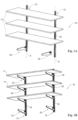
- FIGs. 1A and 1B of the drawings there is illustrated a rack system according to an example of the disclosure, generally designated 10.
- the rack system illustrated in the example is a shelving system, comprising a plurality of shelves 11, though it is appreciated that the rack system can assume different configurations for different purposes.
- the rack system 10 comprises two support rails 12 parallelly extending, vertically, along a longitudinal axis X.
- the support rails 12 are configured for articulation to any wall (not shown) and are configured of sheet metal having a substantially rectangular section with a flat bracket arresting surface 16.
- the bracket arresting surface 16 is configured with two rows of bracket arresting slots 20A and 20B (collectively designated 20) disposed parallelly to axis X.
- the bracket arresting slots are arranged in pairs, horizontally spaced apart at a distance d, equally axially distanced from one another at a distance D, and each slot having a height H and a width W.
- bracket arresting surface 16 is configured with a plurality of locking locations, namely circular openings 26, said openings disposed along the longitudinal axis X and equally distanced from one another, extending between the pairs of bracket arresting slots 20A and 20B.
- Brackets 32 are detachably attached to the support rails 12.
- the bracket 32' has a slightly different design, wherein it is configured with a uniform arm portion extending from a rail engaging end thereof, though is functionally similar to brackets 32 ).
- Each bracket 32 comprises a rigid body 34 extending between a first, rail engaging end 36, and a second, free end 38, wherein the engaging end 36 comprises three pairs of downwardly facing, axially disposed, engaging hooks 40A and 40B (collectively designated 40) projecting from the engaging end 36.
- the length L of engaging hooks 40 is slightly less than height H of arresting slots 20 (H>L) and the width S of the engaging hooks 40 is slightly less than the width W of the arresting slots 20 (S ⁇ W).
- the axial distance between axially neighboring engaging hooks 40 is substantially equal to distance D (the axial distance between arresting slots 20).
- the horizontal distance d between a pair of engaging hooks 40A and 40B is substantially equal to distance between a pair of arresting slots 20.
- the engaging hooks 40A and 40B project from an engaging surface 44, said surface configured for sliding engagement over the bracket arresting surface 16 of the support rail 12.
- a top portion of the support bracket 32 defines a support surface 48, which in the present example extends perpendicular to the engaging surface 44.
- the body 34 of the bracket 32 is configured, according to an example, of bent metal sheet material, though it can be made also in different techniques and materials, e.g. of reinforced polymeric material.
- the body comprises two parallelly extending side walls 50 defining therebetween a space 52 of width P.
- Each of the side walls 50 is configured near the rail engaging end 36 with an elliptically shaped window 56, in register with one another, having a long axis laying substantially parallel to a longitudinal axis of the bracket 32.
- a locking mechanism 60 Disposed within the space 52, there is snappingly set a locking mechanism 60 ( Figs. 3-4B ), comprising a rigid body 62 (actuating member) configured at a front end thereof with a tapering locking plunger 64 having a rounded/chamfered tip 65 and a round finger engageable actuating opening 66. Extending from a rear wall of the body 62 there is a spring retention boss 67 ( Fig. 4A ) supporting a coiled compression spring 68. Body 62 has a flat top surface 70 and has a width Z only slightly less than the width P of the space 52 within the bracket 32, thus fitted for sliding displacement within the space 52.
- the actuating opening 60 is configured with a rim 74 having a width R greater than the width P of space 52 (P ⁇ R), said rim being substantially circular with a diameter corresponding with the short axis of the elliptical window 56 of the bracket 32, whereby the locking mechanism 60 is restricted for sliding displacement within and along the long axis of the window 56.
- the locking plunger 64 is normally biased into a projecting position from the engaging end 36 and owing to location of rim 74 within the elliptical window 56, the locking mechanism 60 is restricted to only sliding displacement within the space of the support bracket 32 between said projecting position and a retracted position, against the biasing effect of the coiled spring 68, by an individual manipulating the actuating member 62 in a trigger-like fashion, i.e. by inserting a finger into the opening 66 and displacing it rearwards, against the biasing effect, so that the plunger 64 retracts inwards.
- a bracket 32 is neared to the bracket arresting surface 16 of the support rail 12 ( Figs. 6A , 7A , 8A and 9A ), then the locking mechanism 60 is retracted by pulling it rearwards within the opening 56, resulting in retraction of the plunger 64 ( Figs. 6B , 7B , 8B and 9B ), whereupon the engaging surface 44 of bracket 32 is applied over the bracket arresting surface 16 so that the engaging hooks 40 engage within the arresting slots 20 and further the support bracket is displaced downwards into arresting of the engaging hooks 40 within the arresting slots 20 ( Figs.
Landscapes
- Drawers Of Furniture (AREA)
Description
- The present disclosure concerns rack systems.
- References considered to be relevant as background to the presently disclosed subject matter are listed below:
-
US 5,022,621 -
US 5,185,971 -
US 5,538,213 -
US 6,978,975 -
JP S62 120840 U -
US 5,022,621 is directed to a multi-hooks bracket adapted to hookably attach into vertically spaced and vertically elongated apertures of a multi-apertured column whereby the hookably attached bracket is adapted to cantileverly support office equipment, an improved multi-hooks bracket structure that is resistant to upward dislodgement from the multi-apertured column, said improved bracket structure comprising: (A) a generally horizontally extending arm having a periphery comprising a substantially horizontally upper-edge adapted to support office equipment thereat and also comprising an upright rear-side; (B) a plurality of vertically spaced hooks arrayed along an upright first-plane, each hook extending horizontally rearwardly and then downwardly from the arm rear-side whereby each hook is adapted to extend into and partially occupy the height of a vertically elongate aperture of a said multi-apertured column; and (C) a horizontally elongate lock located along said first-plane and at the arm rear-side, said lock having an elevation between consecutive bracket hooks and being horizontally reciprocatably associated with said arm so as to move along the horizontal portion of a said consecutive hook toward the unoccupied height remainder of a said partially occupied column aperture, and said lock having an inclined notchably serrated rear-end contour adapted to removably securely plug-into said column aperture unoccupied height remainder to thereby prevent upward dislodgement of said bracket from a said multi-apertured column. -
US 5,185,971 discloses a channel adapted to fit within a slotted wall panel, comprising an elongated extruded member, which, in cross section, including: (a) a substantially U-shaped central box member, comprising a face plate adapted to be exposed on and oriented substantially parallel to an exposed surface of the panel, and two box support members extending substantially perpendicular from the face plate, adapted to extend into the panel from the face plate; (b) a flange member extending from each of the support members, comprising a flange plate connected to one of the support members and extending substantially parallel to the face plate, and a flange support member connected to the flange plate and extending substantially perpendicular to the flange plate, the two box support members and the flange support members being oriented substantially parallel to each other, and terminating in substantially the same plane. -
US 5,538,213 discloses a support bracket for shelving comprising a main body having a vertical edge from which extend a plurality of spaced apart, outwardly directed hooks for mounting the bracket on a vertical support standard with said hooks extending into vertically spaced apertures in the standard; a lock for preventing removal of the bracket from the standard, said lock comprising a member that is movably mounted on the main body of the bracket for displacement towards and away from the support standard between a locked and unlocked position and including a portion adapted to engage in an aperture of the support standard, the lock being disposed on the vertical edge of the main body so that it enters and at least partially occupies an aperture of the support standard that is not partially occupied by one of the bracket's hooks. -
US 6,978,975 discloses a shelf system for releasable mounting of shelves or boards on a wall or standing by itself, said shelf system comprising: at least one supporting element which is essentially vertically positioned and has slots or grooves, at least one plate-shaped shelf bracket having a longitudinal plane which is adapted to support said shelf or board and which by means of a hook-shaped portion projecting from one end of said shelf bracket is adapted to be inserted into a chosen slot and engage with an area of the supporting element adjacent to the slot for sustaining the shelf bracket in the supporting element, and a locking element for releasable locking of the shelf bracket on the supporting element, wherein the hook-shaped portion has a fastening end which is directed upwards in a mounting position of the shelf bracket and is defined by a recess in the shelf bracket and by an essentially arc-shaped circumferential surface extending downwards from the uppermost portion of the recess and terminating at said end of said shelf bracket, wherein the distance between the termination of said circumferential surface and the recess corresponds to the height of the slot in order to enable the hook shaped portion to fit through the slot, wherein the shelf bracket is adapted to be applied obliquely from above into the supporting element and subsequently be pivoted in place downwards, and wherein the recess has a width that is greater than the material thickness of the supporting element in said slot area for releasable receiving of the locking element, which locking element is adapted to be positioned perpendicular to the longitudinal plane of the shelf bracket and the width of the recess is small enough such that the recess engages with the locking element to prevent the shelf bracket from being unintentionally detached from the supporting element when the locking element is in the recess, whereby the shelf bracket is locked in a releasable manner on the supporting element. - A further support bracket is known from
JP S62 120840 U - According to a first aspect of the present invention there is provided a rack system according to claim 14, said rack system comprising at least one support rail configured with a plurality of axially extending bracket arresting slots and a plurality of corresponding locking locations, and at least one support bracket comprising at least two axially disposed engaging hooks readily detachably attachable with any two or more of the bracket arresting slots of the support rail, said support bracket further comprising a locking mechanism comprising a locking plunger configured for engaging with a locking location at the support rail.
- The term rack system is used in its broad sense and denotes any rack support system configured as a wall mountable rack support system, for any purpose, e.g. a shelving system and the like. The term wall refers to any support element to which a support rail according to the disclosure can be applied, either stationary or mobile.
- The term support bracket denotes a cantilever-type element detachably attachable to a support rail, said support bracket can be used for supporting any type of load, e.g. shelves, cargo, containers and the like, any items of utility and the like.
- The arrangement is such that the support bracket can be attached or detached from the support rail only when the locking plunger is disengaged from a locking location, thereby preventing unintentional detaching, or attaching, of the support bracket from the support rail.
- According to a particular example, the support rail is configured with a bracket arresting surface, comprising a plurality of paired bracket arresting slots, parallelly disposed in two rows, and the plurality of locking locations are configured as locking openings disposed in correspondence with each pair of slots, said locking openings disposed along a longitudinal axis extending between said rows.
- According to another aspect of the present invention there is provided a support bracket according to claim 1, said support bracket being configured for detachably attaching to a support rail, said support bracket comprising a body extending between a first, engaging end, and a second end, wherein the engaging end comprises at least a pair of axially disposed engaging hooks projecting from the engaging end and configured for sliding engagement within bracket arresting slots of a support rail, and a locking mechanism comprising a locking plunger normally biased into a projecting position from the engaging end, and a actuating member for displacing the locking plunger into a retracted position.
- The engaging end of the support bracket defines an engaging surface configured for at least partially sliding and bearing over at least a portion of the bracket arresting surface of the support rail.
- According to one example, the support bracket has a body comprising two parallelly extending side walls with a space therebetween, at least near the engaging end, said space accommodating the locking mechanism, with an actuation opening at least at one of the side walls extending in register with a portion of the locking mechanism.
- According to a particular example, the support bracket is configured with two or more pairs of parallelly disposed engaging hooks, and wherein each pair of engaging hooks is equally spaced from each other pair of engaging hooks along the longitudinal axis.
- Any one or more of the following features, designs and configurations can be applied to the support bracket and/or rack system according to the present disclosure, separately and in various combinations thereof:
- The engaging hooks of the support bracket can coextend from the side walls of the body;
- The engaging hooks of the support bracket can extend flush with the side walls of the body;
- The engaging hooks can be axially disposed along a longitudinal axis of the support bracket, and the engaging surface of the body can extend along an axis normal to said longitudinal axis;
- The support rail can be configured for attaching to any substantially vertically extending support wall or any carrying wall surface;
- The body of the support bracket can be made of sheet metal;
- The body of the support bracket can be made of reinforced molded polymer;
- The locking mechanism of the support bracket can comprise more than one locking plunger, all of which being actuated between a normally projecting position and a retracted position by manipulating a single actuating member;
- When the locking plunger of the support bracket is received within a locking opening of the support rail, the engaging surface of the support bracket is prohibited from sliding over the bracket arresting surface of the support rail, thus prohibiting axial sliding displacement into engagement or disengagement from the support rail;
- The actuating member can be configured for only sliding displacement within the space extending between the side walls of the body;
- Manipulating the retracing member can be in a trigger-like actuation fashion, actuated by a single finger;
- The locking plunger can be integral with the actuating member;
- The actuating member with the locking plunger can be biased into the projecting position by a biasing member extending between a bearing portion of the extracting member and a support portion of body;
- The bearing portion and the support portion can be coaxially configured;
- The support portion of the body can be configured as a surface inwardly extending from a side wall of the body;
- The biasing member can be a coiled spring extending between the bearing portion and the support portion;
- The bracket arresting locations can be configured as parallelly disposed slots axially extending along the longitudinal axis;
- The locking locations can be configured as round openings;
- A tip of the plunger can be rounded or chamfered to facilitate easy engagement within corresponding locking locations of the support rail;
- The locking locations can be disposed in register with the plurality of bracket arresting locations;
- The locking locations and the bracket arresting locations are equidistantly distributed along a longitudinal axis;
- The body of the support bracket can be configured out of a unitary folded sheet material;
- A spring support portion of body can be an integral portion of a side wall, bent into the accommodating space;
- The locking mechanism can be snappingly articulated within the space;
- The support bracket can be used as a single member bearing a load, or it can be used in pairs;
- The support bracket can be configured with one or more articulating locations, for securing thereto a variety of utility units;
- The one or more articulating locations can be disposed over, under and a side walls of said support bracket;
- At least a top portion of the support bracket can be configured with an articulation mechanism for detachably attaching thereto a variety of utility units;
- The articulation mechanism can be configured as a snap-type coupling, bayonet coupling, male-female coupling, dovetail coupling, clasp and latch coupling etc.;
- The support bracket can be configured for sliding supporting one or more utility units or a utility support platform, which said utility support platform is configured for detachably attaching thereto one or more utility units.
- The term utility unit as used herein denotes any article of utility, either stationary of mobile, having a utility and being detachable attachable to other utility units. A utility unit according to the present disclosure can be, by way of example, any type of container, drawer shed, work surface, locomotion system, mounting system, and the like.
- In order to better understand the subject matter that is disclosed herein and to exemplify how it may be carried out in practice, embodiments will now be described, by way of a non-limiting example only, with reference to the accompanying drawings, in which:
-
Fig. 1A is a top perspective view of a rack system according to an embodiment of the present disclosure; -
Fig. 1B is a bottom perspective view of a rack system according to an embodiment of the present disclosure; -
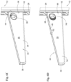
Fig. 2A is a top perspective view of a support bracket according to an exemplary design of the disclosure, articulated to a support rail; -
Fig. 2B is a bottom perspective view of a support bracket according to an exemplary design of the disclosure, articulated to a support rail; -
Fig. 3 is an exploded rear perspective view of a support bracket ofFig. 2A ; -
Fig. 4A is a front perspective view of a locking mechanism of the support bracket ofFig. 3 ; -
Fig. 4B is a section along line I - I inFig. 4A ; -
Fig. 5A is a rear perspective view of an engaging end portion of the support bracket, at enlarged scale, the locking mechanism at a normally projecting position; -
Fig. 5B is a front perspective view of the portion shown inFig. 5A ; -
Fig. 5C is a section taken along line II - II inFig. 5B ; -
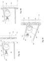
Figs. 6A to 6D are rear perspective views, illustrating consecutive steps of articulating a support bracket to a support rail, according to the present disclosure; -
Figs. 7A to 7D are front perspective views, corresponding with the consecutive steps illustrated inFigs. 6A to 6D ; -
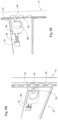
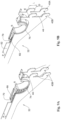
Figs. 8A to 8E are perspective side views of the engaging end, vertically sectioned through a centerline of the support bracket, illustrating consecutive steps of articulating the support bracket to the support rail, according to the present disclosure; -
Fig. 9A is a front perspective view of the engaging end of a bracket, horizontally sectioned along line III - III inFig. 7A , the locking mechanism at the fully projecting position; -
Fig. 9B is a front perspective view of the engaging end of a bracket, horizontally sectioned along line IV - IV inFig. 7C the locking mechanism at the fully retracted position; -
Fig. 9C is a front perspective view of the engaging end of a bracket, vertically sectioned along line V - V inFig. 7A , the locking mechanism at the fully projecting position; and -
Fig. 9D is a front perspective view of the engaging end of a bracket, vertically sectioned along line VI - VI inFig. 7C the locking mechanism at the fully retracted position. - Turning first to
Figs. 1A and 1B of the drawings, there is illustrated a rack system according to an example of the disclosure, generally designated 10. The rack system illustrated in the example is a shelving system, comprising a plurality ofshelves 11, though it is appreciated that the rack system can assume different configurations for different purposes. - With further reference to
Figs. 2A-6D , therack system 10 comprises twosupport rails 12 parallelly extending, vertically, along a longitudinal axis X. The support rails 12 are configured for articulation to any wall (not shown) and are configured of sheet metal having a substantially rectangular section with a flatbracket arresting surface 16. Thebracket arresting surface 16 is configured with two rows ofbracket arresting slots 20A and 20B (collectively designated 20) disposed parallelly to axis X. The bracket arresting slots are arranged in pairs, horizontally spaced apart at a distance d, equally axially distanced from one another at a distance D, and each slot having a height H and a width W. - Further,
bracket arresting surface 16 is configured with a plurality of locking locations, namelycircular openings 26, said openings disposed along the longitudinal axis X and equally distanced from one another, extending between the pairs ofbracket arresting slots 20A and 20B. - A plurality of
brackets 32 are detachably attached to the support rails 12. InFig. 2A the bracket 32' has a slightly different design, wherein it is configured with a uniform arm portion extending from a rail engaging end thereof, though is functionally similar to brackets 32). Eachbracket 32 comprises arigid body 34 extending between a first,rail engaging end 36, and a second,free end 38, wherein theengaging end 36 comprises three pairs of downwardly facing, axially disposed, engaginghooks engaging end 36. The length L of engaginghooks 40 is slightly less than height H of arresting slots 20 (H>L) and the width S of the engaging hooks 40 is slightly less than the width W of the arresting slots 20 (S<W). Further wherein the axial distance between axially neighboring engaginghooks 40 is substantially equal to distance D (the axial distance between arresting slots 20). The horizontal distance d between a pair of engaginghooks slots 20. - The engaging
hooks surface 44, said surface configured for sliding engagement over thebracket arresting surface 16 of thesupport rail 12. A top portion of thesupport bracket 32 defines asupport surface 48, which in the present example extends perpendicular to the engagingsurface 44. - The
body 34 of thebracket 32 is configured, according to an example, of bent metal sheet material, though it can be made also in different techniques and materials, e.g. of reinforced polymeric material. The body comprises two parallelly extendingside walls 50 defining therebetween aspace 52 of width P. Each of theside walls 50 is configured near therail engaging end 36 with an elliptically shapedwindow 56, in register with one another, having a long axis laying substantially parallel to a longitudinal axis of thebracket 32. - Disposed within the
space 52, there is snappingly set a locking mechanism 60 (Figs. 3-4B ), comprising a rigid body 62 (actuating member) configured at a front end thereof with atapering locking plunger 64 having a rounded/chamferedtip 65 and a round fingerengageable actuating opening 66. Extending from a rear wall of thebody 62 there is a spring retention boss 67 (Fig. 4A ) supporting acoiled compression spring 68.Body 62 has a flattop surface 70 and has a width Z only slightly less than the width P of thespace 52 within thebracket 32, thus fitted for sliding displacement within thespace 52. Theactuating opening 60 is configured with arim 74 having a width R greater than the width P of space 52 (P<R), said rim being substantially circular with a diameter corresponding with the short axis of theelliptical window 56 of thebracket 32, whereby thelocking mechanism 60 is restricted for sliding displacement within and along the long axis of thewindow 56. - When assembling the
locking mechanism 60 in thesupport bracket 32, it is snappingly applied into thespace 52, with therim 74 received within thewindow 56, and with a rear end of biasingspring 68 bearing against asupport wall portion 79 cut out of awall 50 and extending into thespace 52. - At the assembled position the locking
plunger 64 is normally biased into a projecting position from theengaging end 36 and owing to location ofrim 74 within theelliptical window 56, thelocking mechanism 60 is restricted to only sliding displacement within the space of thesupport bracket 32 between said projecting position and a retracted position, against the biasing effect of the coiledspring 68, by an individual manipulating the actuatingmember 62 in a trigger-like fashion, i.e. by inserting a finger into theopening 66 and displacing it rearwards, against the biasing effect, so that theplunger 64 retracts inwards. - In use, with reference to
Figs. 6A-9D , abracket 32 is neared to thebracket arresting surface 16 of the support rail 12 (Figs. 6A ,7A ,8A and9A ), then thelocking mechanism 60 is retracted by pulling it rearwards within theopening 56, resulting in retraction of the plunger 64 (Figs. 6B ,7B ,8B and9B ), whereupon the engagingsurface 44 ofbracket 32 is applied over thebracket arresting surface 16 so that the engaginghooks 40 engage within the arrestingslots 20 and further the support bracket is displaced downwards into arresting of the engaginghooks 40 within the arresting slots 20 (Figs. 6C ,7C ,8C and9C ), finally (after the actuatingmember 62 is released) allowing the lockingplunger 64 to spontaneously engage within a corresponding locking locations (openings 26). Once the lockingplunger 64 is engaged within arespective locking openings 26, the support bracket can no longer be axially displaced along therail 12, namely the support brackets is engaged with therail 12 and cannot unintentionally disengage therefrom, unless the locking mechanism is disengaged by retraction of the plunger.
Claims (14)
- A support bracket (32) configured for detachably attaching to a support rail (12), said support bracket comprising a body (34) extending between a first, engaging end (36), and a second end (38), wherein the engaging end (36) comprises at least a pair of axially disposed engaging hooks (40) projecting from the engaging end and configured for sliding engagement within bracket arresting slots (20) of the support rail (12), and a locking mechanism (60) comprising a locking plunger (64) normally biased into a projecting position from the engaging end (36), and a actuating member (62) for displacing the locking plunger into a retracted position, wherein the actuating member (62) is accommodated within a space (52) of the body defined between two parallelly disposed side walls (50),the actuating member (62) being configured with a body portion having a body width (Z) corresponding with the width (P) of the space (52) between the parallelly extending side walls (50) of the bracket body, and a sliding limit projecting from the body portion, having a width greater then said space width and projecting into actuation openings (56) of the side wall, thereby restricting sliding displacement of the retracing member between a forward projecting position and a rearward, retracted position,the body portion of the actuating member being configured with a through-going finger engaging location (66), disposed in register with actuation openings (56) at the side walls, said finger engaging location being smaller than the actuation openings and configured with a laterally projecting rim portion (74) defining said sliding limit.
- The support bracket of claim 1, wherein the engaging end of the support bracket defines an engaging surface configured for at least partially sliding and bearing over at least a portion of the bracket arresting surface of the support rail.
- The support bracket of claim 1, configured with two or more pairs of parallelly disposed engaging hooks (40), and wherein each pair of engaging hooks is equally spaced from each other pair of engaging hooks along the longitudinal axis.
- The support bracket of claim 1, configured with one or more articulating locations, for securing thereto a variety of utility units.
- The support bracket of claim 1, configured with an articulation mechanism for detachably attaching thereto a variety of utility units.
- The support bracket of claim 1, configured for sliding supporting one or more utility units or a utility support platform, which in turn is configured for detachably attaching thereto one or more utility units.
- The support bracket of claim 1, wherein the engaging hooks of the support bracket coextend flush from the side walls of the body.
- The support bracket of claim 1, wherein the engaging hooks of the support bracket are axially disposed along a longitudinal axis of the support bracket, and the engaging surface of the body extends along an axis normal to said longitudinal axis.
- The support bracket of claim 1, wherein the locking mechanism of the support bracket comprises one or more of said locking plungers (64), all of which being actuated between a normally projecting position and a retracted position by manipulating a single actuating member.
- The support bracket of claim 1, wherein when the locking plunger of the support bracket is received within the locking opening of the support rail, the engaging surface of the support bracket is prohibited from sliding over the bracket arresting surface of the support rail, and prohibiting axial sliding displacement into engagement or disengagement from the support rail.
- The support bracket of claim 1, wherein the actuating member is configured for only sliding displacement within the space extending between the side walls of the body.
- The support bracket of claim 1, wherein the actuating member with the locking plunger is biased into the projecting position by a biasing member extending between a bearing portion of the actuating member and a support portion of body.
- The support bracket of claim 1, wherein the locking mechanism is snappingly articulated within the space.
- A rack system (10) comprising at least one support rail (12) configured with a plurality of axially extending bracket arresting slots (20) and a plurality of corresponding locking locations (26), and at least one support bracket (32) according to claim 1.
Applications Claiming Priority (2)
| Application Number | Priority Date | Filing Date | Title |
|---|---|---|---|
| IL260350A IL260350B (en) | 2018-07-01 | 2018-07-01 | Midoff system |
| PCT/IL2019/050679 WO2020008448A1 (en) | 2018-07-01 | 2019-06-18 | Rack system |
Publications (2)
| Publication Number | Publication Date |
|---|---|
| EP3813591A1 EP3813591A1 (en) | 2021-05-05 |
| EP3813591B1 true EP3813591B1 (en) | 2024-10-02 |
Family
ID=66624854
Family Applications (1)
| Application Number | Title | Priority Date | Filing Date |
|---|---|---|---|
| EP19737919.1A Active EP3813591B1 (en) | 2018-07-01 | 2019-06-18 | Rack system |
Country Status (5)
| Country | Link |
|---|---|
| US (1) | US11395547B2 (en) |
| EP (1) | EP3813591B1 (en) |
| IL (1) | IL260350B (en) |
| PL (1) | PL3813591T3 (en) |
| WO (1) | WO2020008448A1 (en) |
Families Citing this family (1)
| Publication number | Priority date | Publication date | Assignee | Title |
|---|---|---|---|---|
| US20240341474A1 (en) * | 2023-04-12 | 2024-10-17 | Scott W. Coons | Wall-mounted storage/display system for firearms, tools, wine bottles, or other collections |
Family Cites Families (18)
| Publication number | Priority date | Publication date | Assignee | Title |
|---|---|---|---|---|
| US2622834A (en) * | 1946-08-17 | 1952-12-23 | Sparring Birger | Shelving |
| US3351212A (en) * | 1966-01-07 | 1967-11-07 | Interlake Steel Corp | Pallet rack construction |
| US4171789A (en) * | 1978-04-24 | 1979-10-23 | Steelcase Inc. | Hanger bracket lock |
| US4406374A (en) * | 1981-08-12 | 1983-09-27 | Myco, Inc. | Locking device for display rack |
| JPH0349536Y2 (en) | 1986-01-24 | 1991-10-23 | ||
| US5022621A (en) | 1990-05-09 | 1991-06-11 | Quest Thomas A | Multi-hooks bracket for cantileverly supporting office equipment |
| JP2512857Y2 (en) | 1990-07-31 | 1996-10-02 | 株式会社イトーキクレビオ | Bracket fall prevention device |
| US5116007A (en) * | 1990-09-13 | 1992-05-26 | E.Z. Shelf Company | Eccentric disc lock bracket |
| US5185971A (en) | 1991-05-17 | 1993-02-16 | Johnson Jr Hugh L | Channeled wall panel |
| US5494246A (en) * | 1994-06-17 | 1996-02-27 | Haworth, Inc. | Passive lock for end panel assembly |
| US5538213A (en) | 1994-09-21 | 1996-07-23 | Brown Office Systems, Inc. | Bracket for shelving, furniture and the like |
| US6202965B1 (en) | 1998-12-21 | 2001-03-20 | The Marvel Group, Inc. | Panel fastening system for modular office furniture |
| SE516876C2 (en) | 1999-11-02 | 2002-03-19 | Elfa Sweden Ab | Shelf system for releasable mounting of shelves, discs or the like, disc-shaped bracket and locking element for such a shelf system |
| US7497344B2 (en) * | 2006-03-22 | 2009-03-03 | Protrend Co., Ltd. | Supporting bracket for wall-mount rack |
| US20070257169A1 (en) * | 2006-04-20 | 2007-11-08 | Brad Taggett | Quick Release Power Strip Bracket assembly |
| US20080067909A1 (en) * | 2006-09-15 | 2008-03-20 | Norcold, Inc. | Shelf support arm with locking mechanism |
| GB2449934B (en) * | 2007-06-08 | 2011-08-31 | Protrend Co Ltd | Multipurpose wall-mount rack |
| DE202009013523U1 (en) * | 2009-10-07 | 2010-03-11 | Atrium Enterprises Gmbh | Pegboard |
-
2018
- 2018-07-01 IL IL260350A patent/IL260350B/en unknown
-
2019
- 2019-06-18 WO PCT/IL2019/050679 patent/WO2020008448A1/en not_active Ceased
- 2019-06-18 US US16/973,751 patent/US11395547B2/en active Active
- 2019-06-18 EP EP19737919.1A patent/EP3813591B1/en active Active
- 2019-06-18 PL PL19737919.1T patent/PL3813591T3/en unknown
Also Published As
| Publication number | Publication date |
|---|---|
| IL260350B (en) | 2022-04-01 |
| EP3813591A1 (en) | 2021-05-05 |
| WO2020008448A1 (en) | 2020-01-09 |
| PL3813591T3 (en) | 2025-02-17 |
| IL260350A (en) | 2019-01-31 |
| US20210251383A1 (en) | 2021-08-19 |
| US11395547B2 (en) | 2022-07-26 |
Similar Documents
| Publication | Publication Date | Title |
|---|---|---|
| AU2018247317B2 (en) | System including article support surface and dividers | |
| CA2245001C (en) | Removable bottom standing divider unit | |
| US7694925B2 (en) | Storage systems having storage accessory with locking tab | |
| US11178964B2 (en) | Mounting system with horizontally-slideable bracket and support bracket | |
| US8622493B2 (en) | Furniture pull-out | |
| US6273534B1 (en) | Shelving accessory mounting system for a cabinet assembly | |
| EP1221876B1 (en) | Pull-out shelf | |
| CA2672127C (en) | Storage systems and methods of use of the same | |
| US4633789A (en) | Toolless mounting arrangement | |
| US10046719B2 (en) | Modular shelving assembly | |
| US5022621A (en) | Multi-hooks bracket for cantileverly supporting office equipment | |
| US20100213334A1 (en) | Shelf mounting system | |
| US9591932B2 (en) | Bracket and wall standard assembly | |
| US11395547B2 (en) | Rack system | |
| US7775492B2 (en) | Mounting system and apparatus for attaching accessories to a wall panel | |
| US12232616B2 (en) | Wall and ceiling track system for mounting devices | |
| US4830440A (en) | Tool-free cabinet attachment | |
| US4215784A (en) | Wall bracket assembly | |
| US20120217359A1 (en) | Upright adapter for shelving systems | |
| JP6050956B2 (en) | Storage fixtures | |
| EP1986522B1 (en) | Shelving brackets | |
| JP5851203B2 (en) | Optional member mounting structure and cart apparatus provided with the same | |
| CA1241364A (en) | Toolless mounting arrangement | |
| WO2021080526A1 (en) | Fastening element for a guide rail | |
| JP4358360B2 (en) | Side plate mounting structure to shelf |
Legal Events
| Date | Code | Title | Description |
|---|---|---|---|
| STAA | Information on the status of an ep patent application or granted ep patent |
Free format text: STATUS: UNKNOWN |
|
| STAA | Information on the status of an ep patent application or granted ep patent |
Free format text: STATUS: THE INTERNATIONAL PUBLICATION HAS BEEN MADE |
|
| PUAI | Public reference made under article 153(3) epc to a published international application that has entered the european phase |
Free format text: ORIGINAL CODE: 0009012 |
|
| STAA | Information on the status of an ep patent application or granted ep patent |
Free format text: STATUS: REQUEST FOR EXAMINATION WAS MADE |
|
| 17P | Request for examination filed |
Effective date: 20201203 |
|
| AK | Designated contracting states |
Kind code of ref document: A1 Designated state(s): AL AT BE BG CH CY CZ DE DK EE ES FI FR GB GR HR HU IE IS IT LI LT LU LV MC MK MT NL NO PL PT RO RS SE SI SK SM TR |
|
| DAV | Request for validation of the european patent (deleted) | ||
| DAX | Request for extension of the european patent (deleted) | ||
| RAP3 | Party data changed (applicant data changed or rights of an application transferred) |
Owner name: KETER HOME AND GARDEN PRODUCTS LTD. |
|
| STAA | Information on the status of an ep patent application or granted ep patent |
Free format text: STATUS: EXAMINATION IS IN PROGRESS |
|
| 17Q | First examination report despatched |
Effective date: 20230818 |
|
| GRAP | Despatch of communication of intention to grant a patent |
Free format text: ORIGINAL CODE: EPIDOSNIGR1 |
|
| GRAP | Despatch of communication of intention to grant a patent |
Free format text: ORIGINAL CODE: EPIDOSNIGR1 |
|
| STAA | Information on the status of an ep patent application or granted ep patent |
Free format text: STATUS: GRANT OF PATENT IS INTENDED |
|
| INTG | Intention to grant announced |
Effective date: 20240614 |
|
| GRAS | Grant fee paid |
Free format text: ORIGINAL CODE: EPIDOSNIGR3 |
|
| GRAA | (expected) grant |
Free format text: ORIGINAL CODE: 0009210 |
|
| STAA | Information on the status of an ep patent application or granted ep patent |
Free format text: STATUS: THE PATENT HAS BEEN GRANTED |
|
| AK | Designated contracting states |
Kind code of ref document: B1 Designated state(s): AL AT BE BG CH CY CZ DE DK EE ES FI FR GB GR HR HU IE IS IT LI LT LU LV MC MK MT NL NO PL PT RO RS SE SI SK SM TR |
|
| REG | Reference to a national code |
Ref country code: GB Ref legal event code: FG4D |
|
| REG | Reference to a national code |
Ref country code: CH Ref legal event code: EP |
|
| REG | Reference to a national code |
Ref country code: DE Ref legal event code: R096 Ref document number: 602019059717 Country of ref document: DE |
|
| P01 | Opt-out of the competence of the unified patent court (upc) registered |
Free format text: CASE NUMBER: APP_51729/2024 Effective date: 20240913 |
|
| REG | Reference to a national code |
Ref country code: IE Ref legal event code: FG4D |
|
| REG | Reference to a national code |
Ref country code: NL Ref legal event code: FP |
|
| REG | Reference to a national code |
Ref country code: LT Ref legal event code: MG9D |
|
| REG | Reference to a national code |
Ref country code: AT Ref legal event code: MK05 Ref document number: 1727844 Country of ref document: AT Kind code of ref document: T Effective date: 20241002 |
|
| PG25 | Lapsed in a contracting state [announced via postgrant information from national office to epo] |
Ref country code: HR Free format text: LAPSE BECAUSE OF FAILURE TO SUBMIT A TRANSLATION OF THE DESCRIPTION OR TO PAY THE FEE WITHIN THE PRESCRIBED TIME-LIMIT Effective date: 20241002 Ref country code: PT Free format text: LAPSE BECAUSE OF FAILURE TO SUBMIT A TRANSLATION OF THE DESCRIPTION OR TO PAY THE FEE WITHIN THE PRESCRIBED TIME-LIMIT Effective date: 20250203 Ref country code: IS Free format text: LAPSE BECAUSE OF FAILURE TO SUBMIT A TRANSLATION OF THE DESCRIPTION OR TO PAY THE FEE WITHIN THE PRESCRIBED TIME-LIMIT Effective date: 20250202 |
|
| PG25 | Lapsed in a contracting state [announced via postgrant information from national office to epo] |
Ref country code: FI Free format text: LAPSE BECAUSE OF FAILURE TO SUBMIT A TRANSLATION OF THE DESCRIPTION OR TO PAY THE FEE WITHIN THE PRESCRIBED TIME-LIMIT Effective date: 20241002 |
|
| PG25 | Lapsed in a contracting state [announced via postgrant information from national office to epo] |
Ref country code: BG Free format text: LAPSE BECAUSE OF FAILURE TO SUBMIT A TRANSLATION OF THE DESCRIPTION OR TO PAY THE FEE WITHIN THE PRESCRIBED TIME-LIMIT Effective date: 20241002 |
|
| PG25 | Lapsed in a contracting state [announced via postgrant information from national office to epo] |
Ref country code: ES Free format text: LAPSE BECAUSE OF FAILURE TO SUBMIT A TRANSLATION OF THE DESCRIPTION OR TO PAY THE FEE WITHIN THE PRESCRIBED TIME-LIMIT Effective date: 20241002 |
|
| PG25 | Lapsed in a contracting state [announced via postgrant information from national office to epo] |
Ref country code: NO Free format text: LAPSE BECAUSE OF FAILURE TO SUBMIT A TRANSLATION OF THE DESCRIPTION OR TO PAY THE FEE WITHIN THE PRESCRIBED TIME-LIMIT Effective date: 20250102 |
|
| PG25 | Lapsed in a contracting state [announced via postgrant information from national office to epo] |
Ref country code: AT Free format text: LAPSE BECAUSE OF FAILURE TO SUBMIT A TRANSLATION OF THE DESCRIPTION OR TO PAY THE FEE WITHIN THE PRESCRIBED TIME-LIMIT Effective date: 20241002 Ref country code: LV Free format text: LAPSE BECAUSE OF FAILURE TO SUBMIT A TRANSLATION OF THE DESCRIPTION OR TO PAY THE FEE WITHIN THE PRESCRIBED TIME-LIMIT Effective date: 20241002 Ref country code: GR Free format text: LAPSE BECAUSE OF FAILURE TO SUBMIT A TRANSLATION OF THE DESCRIPTION OR TO PAY THE FEE WITHIN THE PRESCRIBED TIME-LIMIT Effective date: 20250103 |
|
| PG25 | Lapsed in a contracting state [announced via postgrant information from national office to epo] |
Ref country code: CZ Free format text: LAPSE BECAUSE OF FAILURE TO SUBMIT A TRANSLATION OF THE DESCRIPTION OR TO PAY THE FEE WITHIN THE PRESCRIBED TIME-LIMIT Effective date: 20241002 |
|
| PG25 | Lapsed in a contracting state [announced via postgrant information from national office to epo] |
Ref country code: RS Free format text: LAPSE BECAUSE OF FAILURE TO SUBMIT A TRANSLATION OF THE DESCRIPTION OR TO PAY THE FEE WITHIN THE PRESCRIBED TIME-LIMIT Effective date: 20250102 |
|
| PG25 | Lapsed in a contracting state [announced via postgrant information from national office to epo] |
Ref country code: SM Free format text: LAPSE BECAUSE OF FAILURE TO SUBMIT A TRANSLATION OF THE DESCRIPTION OR TO PAY THE FEE WITHIN THE PRESCRIBED TIME-LIMIT Effective date: 20241002 |
|
| REG | Reference to a national code |
Ref country code: DE Ref legal event code: R097 Ref document number: 602019059717 Country of ref document: DE |
|
| PGFP | Annual fee paid to national office [announced via postgrant information from national office to epo] |
Ref country code: DE Payment date: 20250528 Year of fee payment: 7 |
|
| PG25 | Lapsed in a contracting state [announced via postgrant information from national office to epo] |
Ref country code: DK Free format text: LAPSE BECAUSE OF FAILURE TO SUBMIT A TRANSLATION OF THE DESCRIPTION OR TO PAY THE FEE WITHIN THE PRESCRIBED TIME-LIMIT Effective date: 20241002 |
|
| PGFP | Annual fee paid to national office [announced via postgrant information from national office to epo] |
Ref country code: GB Payment date: 20250522 Year of fee payment: 7 |
|
| PGFP | Annual fee paid to national office [announced via postgrant information from national office to epo] |
Ref country code: NL Payment date: 20250613 Year of fee payment: 7 |
|
| PG25 | Lapsed in a contracting state [announced via postgrant information from national office to epo] |
Ref country code: EE Free format text: LAPSE BECAUSE OF FAILURE TO SUBMIT A TRANSLATION OF THE DESCRIPTION OR TO PAY THE FEE WITHIN THE PRESCRIBED TIME-LIMIT Effective date: 20241002 |
|
| PGFP | Annual fee paid to national office [announced via postgrant information from national office to epo] |
Ref country code: FR Payment date: 20250610 Year of fee payment: 7 |
|
| PG25 | Lapsed in a contracting state [announced via postgrant information from national office to epo] |
Ref country code: RO Free format text: LAPSE BECAUSE OF FAILURE TO SUBMIT A TRANSLATION OF THE DESCRIPTION OR TO PAY THE FEE WITHIN THE PRESCRIBED TIME-LIMIT Effective date: 20241002 |
|
| PG25 | Lapsed in a contracting state [announced via postgrant information from national office to epo] |
Ref country code: SK Free format text: LAPSE BECAUSE OF FAILURE TO SUBMIT A TRANSLATION OF THE DESCRIPTION OR TO PAY THE FEE WITHIN THE PRESCRIBED TIME-LIMIT Effective date: 20241002 |
|
| PG25 | Lapsed in a contracting state [announced via postgrant information from national office to epo] |
Ref country code: IT Free format text: LAPSE BECAUSE OF FAILURE TO SUBMIT A TRANSLATION OF THE DESCRIPTION OR TO PAY THE FEE WITHIN THE PRESCRIBED TIME-LIMIT Effective date: 20241002 |
|
| PLBE | No opposition filed within time limit |
Free format text: ORIGINAL CODE: 0009261 |
|
| STAA | Information on the status of an ep patent application or granted ep patent |
Free format text: STATUS: NO OPPOSITION FILED WITHIN TIME LIMIT |
|
| PG25 | Lapsed in a contracting state [announced via postgrant information from national office to epo] |
Ref country code: SE Free format text: LAPSE BECAUSE OF FAILURE TO SUBMIT A TRANSLATION OF THE DESCRIPTION OR TO PAY THE FEE WITHIN THE PRESCRIBED TIME-LIMIT Effective date: 20241002 |
|
| 26N | No opposition filed |
Effective date: 20250703 |
|
| PGFP | Annual fee paid to national office [announced via postgrant information from national office to epo] |
Ref country code: PL Payment date: 20250527 Year of fee payment: 7 |
|
| REG | Reference to a national code |
Ref country code: CH Ref legal event code: H13 Free format text: ST27 STATUS EVENT CODE: U-0-0-H10-H13 (AS PROVIDED BY THE NATIONAL OFFICE) Effective date: 20260127 |
|
| PG25 | Lapsed in a contracting state [announced via postgrant information from national office to epo] |
Ref country code: MC Free format text: LAPSE BECAUSE OF FAILURE TO SUBMIT A TRANSLATION OF THE DESCRIPTION OR TO PAY THE FEE WITHIN THE PRESCRIBED TIME-LIMIT Effective date: 20241002 |
|
| PG25 | Lapsed in a contracting state [announced via postgrant information from national office to epo] |
Ref country code: LU Free format text: LAPSE BECAUSE OF NON-PAYMENT OF DUE FEES Effective date: 20250618 |
|
| REG | Reference to a national code |
Ref country code: BE Ref legal event code: MM Effective date: 20250630 |
|
| PG25 | Lapsed in a contracting state [announced via postgrant information from national office to epo] |
Ref country code: IE Free format text: LAPSE BECAUSE OF NON-PAYMENT OF DUE FEES Effective date: 20250618 |
|
| PG25 | Lapsed in a contracting state [announced via postgrant information from national office to epo] |
Ref country code: BE Free format text: LAPSE BECAUSE OF NON-PAYMENT OF DUE FEES Effective date: 20250630 |
|
| PG25 | Lapsed in a contracting state [announced via postgrant information from national office to epo] |
Ref country code: CH Free format text: LAPSE BECAUSE OF NON-PAYMENT OF DUE FEES Effective date: 20250630 |