EP3813273A2 - Directional wireless communications onboard aircraft - Google Patents
Directional wireless communications onboard aircraft Download PDFInfo
- Publication number
- EP3813273A2 EP3813273A2 EP20202030.1A EP20202030A EP3813273A2 EP 3813273 A2 EP3813273 A2 EP 3813273A2 EP 20202030 A EP20202030 A EP 20202030A EP 3813273 A2 EP3813273 A2 EP 3813273A2
- Authority
- EP
- European Patent Office
- Prior art keywords
- wireless access
- wireless
- directional antenna
- access points
- access point
- Prior art date
- Legal status (The legal status is an assumption and is not a legal conclusion. Google has not performed a legal analysis and makes no representation as to the accuracy of the status listed.)
- Pending
Links
Images



Classifications
-
- H—ELECTRICITY
- H04—ELECTRIC COMMUNICATION TECHNIQUE
- H04W—WIRELESS COMMUNICATION NETWORKS
- H04W76/00—Connection management
- H04W76/10—Connection setup
- H04W76/15—Setup of multiple wireless link connections
-
- H—ELECTRICITY
- H04—ELECTRIC COMMUNICATION TECHNIQUE
- H04B—TRANSMISSION
- H04B7/00—Radio transmission systems, i.e. using radiation field
- H04B7/14—Relay systems
- H04B7/15—Active relay systems
- H04B7/185—Space-based or airborne stations; Stations for satellite systems
- H04B7/18502—Airborne stations
- H04B7/18506—Communications with or from aircraft, i.e. aeronautical mobile service
-
- G—PHYSICS
- G06—COMPUTING OR CALCULATING; COUNTING
- G06F—ELECTRIC DIGITAL DATA PROCESSING
- G06F16/00—Information retrieval; Database structures therefor; File system structures therefor
- G06F16/20—Information retrieval; Database structures therefor; File system structures therefor of structured data, e.g. relational data
- G06F16/23—Updating
- G06F16/2379—Updates performed during online database operations; commit processing
-
- H—ELECTRICITY
- H04—ELECTRIC COMMUNICATION TECHNIQUE
- H04W—WIRELESS COMMUNICATION NETWORKS
- H04W24/00—Supervisory, monitoring or testing arrangements
- H04W24/08—Testing, supervising or monitoring using real traffic
-
- H—ELECTRICITY
- H04—ELECTRIC COMMUNICATION TECHNIQUE
- H04W—WIRELESS COMMUNICATION NETWORKS
- H04W28/00—Network traffic management; Network resource management
- H04W28/02—Traffic management, e.g. flow control or congestion control
- H04W28/06—Optimizing the usage of the radio link, e.g. header compression, information sizing, discarding information
-
- H—ELECTRICITY
- H04—ELECTRIC COMMUNICATION TECHNIQUE
- H04W—WIRELESS COMMUNICATION NETWORKS
- H04W64/00—Locating users or terminals or network equipment for network management purposes, e.g. mobility management
-
- H—ELECTRICITY
- H04—ELECTRIC COMMUNICATION TECHNIQUE
- H04W—WIRELESS COMMUNICATION NETWORKS
- H04W76/00—Connection management
- H04W76/30—Connection release
-
- H—ELECTRICITY
- H04—ELECTRIC COMMUNICATION TECHNIQUE
- H04B—TRANSMISSION
- H04B7/00—Radio transmission systems, i.e. using radiation field
- H04B7/02—Diversity systems; Multi-antenna system, i.e. transmission or reception using multiple antennas
- H04B7/10—Polarisation diversity; Directional diversity
-
- H—ELECTRICITY
- H04—ELECTRIC COMMUNICATION TECHNIQUE
- H04W—WIRELESS COMMUNICATION NETWORKS
- H04W16/00—Network planning, e.g. coverage or traffic planning tools; Network deployment, e.g. resource partitioning or cells structures
- H04W16/24—Cell structures
- H04W16/28—Cell structures using beam steering
-
- H—ELECTRICITY
- H04—ELECTRIC COMMUNICATION TECHNIQUE
- H04W—WIRELESS COMMUNICATION NETWORKS
- H04W52/00—Power management, e.g. Transmission Power Control [TPC] or power classes
- H04W52/04—Transmission power control [TPC]
- H04W52/18—TPC being performed according to specific parameters
- H04W52/26—TPC being performed according to specific parameters using transmission rate or quality of service QoS [Quality of Service]
-
- H—ELECTRICITY
- H04—ELECTRIC COMMUNICATION TECHNIQUE
- H04W—WIRELESS COMMUNICATION NETWORKS
- H04W52/00—Power management, e.g. Transmission Power Control [TPC] or power classes
- H04W52/04—Transmission power control [TPC]
- H04W52/30—Transmission power control [TPC] using constraints in the total amount of available transmission power
- H04W52/36—Transmission power control [TPC] using constraints in the total amount of available transmission power with a discrete range or set of values, e.g. step size, ramping or offsets
- H04W52/367—Power values between minimum and maximum limits, e.g. dynamic range
-
- H—ELECTRICITY
- H04—ELECTRIC COMMUNICATION TECHNIQUE
- H04W—WIRELESS COMMUNICATION NETWORKS
- H04W88/00—Devices specially adapted for wireless communication networks, e.g. terminals, base stations or access point devices
- H04W88/08—Access point devices
Definitions
- the present disclosure relates to the art of wireless communications on aircraft. Passengers, operators and control systems may harness aircraft wireless communications to communicate onboard and offboard aircraft.
- the method includes receiving absolute wireless access point coordinates from wireless access points that define respective wireless access point positions of the wireless access points.
- the method includes orienting the directional antenna to orientations based on the absolute wireless access point coordinates.
- the method includes transmitting test signals to the respective wireless access points while the directional antenna is positioned at the orientations to generate the database entries associated with the respective wireless access point positions.
- the method includes orienting the directional antenna according to a first one of the database entries having a greatest likelihood to establish a first communications path between a first one of the wireless access points and the wireless endpoint.
- the method includes transmitting a data signal to the first one of the wireless access points with a minimum transmission power based on the database entries.
- further embodiments may include that responsive to a disconnection of the first communications path, orienting the directional antenna according to a second one of the database entries having a second greatest likelihood to establish a second communications path between a second one of the wireless access points and the wireless endpoint.
- further embodiments may include wherein the disconnection of the first communications path includes a dropped packet associated with the first communications path.
- further embodiments may include wherein the orienting the directional antenna of the wireless endpoint based on the absolute wireless access point coordinates is according to relative coordinates defined by the absolute wireless access point coordinates and absolute wireless endpoint coordinates that define a wireless endpoint position of the wireless endpoint.
- further embodiments may include wherein the orientations are all positions within an offset band having a step size that corresponds with the relative coordinates.
- further embodiments may include wherein the database entries are ratios of received signal strengths and transmission powers corresponding to the absolute wireless access point coordinates and the greatest likelihood is based on the ratios.
- further embodiments may include wherein the directional antenna is an antenna apparatus that produces ratios according to the relative coordinates such that the ratios vary based on the relative coordinates.
- further embodiments may include wherein the received signal strengths are received from the respective wireless access points as a data transmission.
- test signals are defined by combinations of transmission strength and polarization that vary at the orientations.
- further embodiments may include wherein the database entries are further defined according to the polarization.
- the method includes orienting the directional antenna according to a first one of the database entries having a greatest likelihood to establish a first communications path between a first one of wireless access points and the wireless endpoint.
- further embodiments may include transmitting a data signal to the first one of the wireless access points with a minimum transmission power based on the database entries; and In addition to one or more of the features described above, or as an alternative, further embodiments may include responsive to a disconnection of the first communications path, orienting the directional antenna according to a second one of the database entries having a second greatest likelihood to establish a second communications path between a second one of the wireless access points and the wireless endpoint.
- database entries are defined by a method for initializing wireless communications in an aircraft by recording the database entries for wireless communications in a database schema comprising:
- further embodiments may include wherein the disconnection of the first communications path includes a dropped packet associated with the first communications path.
- further embodiments may include wherein the database entries are ratios of received signal strengths and transmission powers corresponding to absolute wireless access point coordinates and the greatest likelihood is based on the ratios.
- further embodiments may include wherein the directional antenna is an antenna apparatus that produces ratios according to the absolute wireless access point coordinates such that the ratios vary based on the absolute wireless access point coordinates.
- further embodiments may include wherein the received signal strengths are received from the respective wireless access points as a data transmission.
- the controller program product operable to enable orientation of a directional antenna associated with a wireless endpoint on an aircraft.
- the controller program product includes digital storage including database entries associated with a database schema corresponding to connection likelihoods between the wireless endpoint and wireless access points.
- the computer program product includes controller instructions stored on the digital storage operable upon execution by a controller of the wireless endpoint to orient the directional antenna according to a first one of the database entries having a greatest likelihood to establish a first communications path between a first one of wireless access points and the wireless endpoint and transmit a data signal to the first one of the wireless access points with a minimum transmission power defined in the first one of the database entries, the controller instructions further operable upon execution by the controller to responsive to a disconnection of the first communications path, orienting the directional antenna according to a second one of the database entries having a second greatest likelihood to establish a second communications path between a second one of the wireless access points and the wireless endpoint.
- further embodiments may include wherein the disconnection of the first communications path includes a dropped packet associated with the first communications path.
- further embodiments may include wherein the database entries are ratios of received signal strengths and transmission powers corresponding to absolute wireless access point coordinates and the greatest likelihood is based on the ratios.
- further embodiments may include wherein the directional antenna is an antenna apparatus that produces ratios according to the absolute wireless access point coordinates such that the ratios vary based on the absolute wireless access point coordinates.
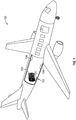
- the aircraft 100 includes a wireless endpoint 102.
- the aircraft 100 may house numerous wireless endpoints 102 for a variety of functions.
- the wireless endpoint 102 may be connected to sensory inputs (e.g., temperature, pressure, force) related to any number of operational inputs.
- the wireless endpoint 102 may provide passenger or cargo communications.
- the wireless endpoint 102 includes a directional antenna 103 and a controller 101.
- the wireless endpoint 102 may be battery powered or powered by aircraft power system.
- the wireless endpoint 102 may be associated with any number of wireless access points 104.
- the directional antenna 103 may be an antenna apparatus configured to direct electromagnetic waves that have different transmission characteristics (e.g., RSSI) that vary based on the orientation of the antenna apparatus.
- the wireless access points 104 may be configured with omnidirectional antennae, directional antennae, or combinations thereof.
- the A wireless endpoint 102 may be disposed throughout the aircraft 100. As an example, the wireless endpoint 102 may be associated with a temperature sensor on the aircraft wing.
- the wireless access points 104 may be dispersed throughout the aircraft on the aircraft wing and the aircraft fuselage.
- the wireless endpoint 102 includes a directional antenna 103 that improves communications with one or more of the wireless access points 104 such that the wireless endpoint 102 can reduce transmission power. Indeed, power consumption of wireless endpoints 102 may be reduced to improve energy consumption of the aircraft 100 or batteries.
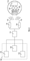
- the network architecture includes the wireless endpoint 102 and wireless access points 104.
- the wireless endpoint 102 includes the direction antenna 103.
- the directional antenna 103 may be any type, including parabolic antennas, phase array antennas, and the like.
- the wireless endpoint 102 may include a radio module 105 for packetization and organization of data communications.
- the wireless endpoint 102 may include an orientation controller 300. As discussed with regard to FIG. 3 the orientation controller 300 may control an orientation of the directional antenna 103.
- the orientation may be mechanical with regard to a parabolic antenna, electromagnetic with regard to a phased array, or another implement.
- the wireless endpoint 102 is configured to communicate with the wireless access points 104 over a first communications path 116 between a first one of the wireless access points 104 and the wireless endpoint 102.
- the wireless endpoint 102 is configured to communicate with the wireless access points 104 over a second communications path 118 between a second one of the wireless access points 104 and the wireless endpoint 102.
- the wireless access points 104 may be associated with a network manager 110.
- the network manager 110 may be a router or a dynamic host configuration protocol (DHCP) server configured to establish and route communications between the wireless access points 104 and flight controls 106.
- the flight controls 106 may include different endpoint controllers 108 (e.g., integrated health management, prognostic health management, engine health management).
- the orientation controller 300 may be disposed on the wireless endpoint 102, in communication with the wireless endpoint 102, or a combination thereof.
- the orientation controller 300 may receive absolute wireless access point coordinates 308 that define a wireless access point position respective the aircraft 100 or another point of origin.
- the orientation controller 300 may receive absolute wireless endpoint coordinates 306 that define a wireless endpoint position respective the aircraft 100 or another point of origin.
- the orientation controller 300 may comprise a transform 302 or computational implement that converts the absolute wireless access point coordinates 308 and absolute wireless endpoint coordinates 306 into relative coordinates 310 for orienting the directional antenna 103.
- the absolute wireless access point coordinates 308 and absolute wireless endpoint coordinates 306 may be used to determine relative coordinates 310 that define a position of the wireless endpoint 102 with respect to respective wireless access point positions.
- the relative coordinates 310 may be used to determine an estimated orientation coordinates 312 of the directional antenna 103 in function block 304.
- the directional antenna 103 may be oriented in an angle that is directed toward one of the wireless access points 104 at a time.
- a coordinate system 400 with orientational angles is shown in accordance with one or more implementations of the present disclosure.
- coordinates are given with respect to the origin (O).
- the origin may be a position on the aircraft 100 for defining the absolute coordinates of the wireless endpoints 102 and the wireless access points 104.
- the origin may be the wireless endpoints 102 or the wireless access points 104 for determination of the relative coordinates 310.
- the coordinates may three-dimensional, including an x-axis 408, y-axis 406, and z-axis 404.
- a directional antenna orientation 402 of the directional antenna 103 corresponds with coordinates 410, 412 of the orientation coordinates 312.
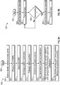
- FIG. 5A portions of an example process 500 associated with analyzing a wireless communications system in accordance with one or more implementations of the present disclosure is shown. It should be appreciated that all processes disclosed herein may include a step-by-step disclosure of the implementation and steps may be added, omitted, or rearranged as necessary. The steps may be further performed in series or in parallel.
- the process 500 begins in step 502.
- the process 500 may be performed during installation or manufacture.
- the process 500 may be performed during operation or in-flight for update or confirmation.
- the wireless endpoint 102 scans to identify wireless access points 104.
- a list of wireless access points 104 is prepared in step 506.
- the first wireless access point 104 is selected by the wireless endpoint 102.
- absolute wireless access point coordinates 308 and absolute wireless endpoint coordinates 306 may be exchanged between the wireless access point 104, and the wireless endpoint 102. It should be appreciated that the wireless access point 104, the wireless endpoint 102, or both may include predefined absolute wireless access point coordinates 308 and absolute wireless endpoint coordinates 306.
- the relative coordinates 310 may be determined by transform 302.
- the directional antenna 103 is oriented to the directional antenna orientation 402.
- test signals are sent to the wireless access points 104 including varying the power transmission level to determine a minimum transmission power required to establish communications with the wireless access point 104 without dropping packets or a communication path.
- Polarization of electromagnetic waves from the wireless endpoint 102 may be adjusted to left or right circular polarization, or any other polarization or strength for that matter, to determine the best communication parameters.
- the reflective properties of the directional antenna 103 may further distort polarization that may require different polarization levels to be evaluated.
- the directional antenna 103 may be oriented within an offset band, offset from the estimated orientation coordinates 312 to determine the minimum transmission power necessary to establish the communications paths 116, 118.
- a step size associated with the directional antenna orientation 402 may adjust the directional antenna orientation 402 within a band that includes the estimated orientation coordinates 312.
- the band may shift based on (RSSI) from the wireless access point 104.
- RSSI may be sent from the wireless access points 104 as a data transmission (e.g., packets including the numerical value of the RSSI).
- the controller 101 associated with the wireless endpoint 102 may include any combination of processors, field programmable gate arrays (FPGA), or application specific integrated circuits (ASIC).
- the controller 101 may include memory, volatile and non-volatile, operable to store machine and controller instructions from the processors and other processing mechanisms to receive, calculate, and control devices, as necessary.
- Machine instructions may be stored (e.g., stored instructions, stored machine instructions, stored steps) in any language or representation, including but not limited to machine code, assembly instructions, C, C++, C#, PASCAL, COBAL, PYTHON, JAVA, and RUBY to form a controller program product. It should be appreciated that any type of wired or wireless configuration is appreciated for any of the communications from the controller 101.
- Wireless protocols such as ZIGBEE, WI-FI, BLUETOOTH, or any other implement may be used. Communications may be realized through any protocol or medium known or unknown. It should be appreciated that the wireless communications disclosed herein may include any protocols (e.g., 802.11), mediums, or components for communicating.
- the controller 101 may be associated with the directional antenna 103 by any number of actuators including electric motors.
- step 518 the RSSI, transmission power, and polarization settings-along with the orientation settings-is stored as database entries, as shown in FIGs. 7A-7B . Some of the parameters or settings may be omitted and other parameters and settings may be added.
- the wireless endpoint 102 After the wireless endpoint 102 has analyzed one or more of the wireless access points 104, the wireless endpoint 102 identifies the wireless access point 104 having the greatest likelihood to establish connection in step 520.
- the wireless access point 104 having the greatest likelihood to establish connection may further be the wireless access point 104 associated with a minimum transmission power, enabling higher likelihood establishment of the communication paths 116, 118 by an increased capacity to increase power transmission levels.
- step 552 an example process 550 associated with establishing communications within wireless communications system is shown in accordance with one or more implementations of the present disclosure.
- the process 550 beings.
- the directional antenna 103 is oriented to improve transmission with a first wireless access point 104 to establish a first communication path 116.
- step 556 data is transmitted between wireless access point 104 and the wireless endpoint 102, communicating a data signal.
- the controller 101 or another implement determines whether a disconnection has occurred. The determination may be based on a loss of signal, dropped packets above a predetermined threshold, improper sequence numbering, or any other situation.
- the directional antenna 103 is oriented to improve transmission with a second wireless access point 104 to establish a second communication path 118 responsive to the disconnection.
- data is transmitted between wireless access point 104 and the wireless endpoint 102 over the second communication path 118. The process may continue, connecting to the highest likelihood connection based on the database entries to ensure continued communications between the wireless endpoint 102 and the wireless access point 104.
- a process 600 associated with wireless communications is shown in accordance with one or more implementations of the present disclosure.
- the wireless access points 104 or wireless endpoints 102 may use the process for parallel processing of access control and communications.
- the process 600 begins.
- the wireless access point 104 determines whether the wireless endpoint 102 is on the access list in step 606. If the wireless endpoint 102 is on the access less in step 606, the wireless access point 104 accepts and acknowledges the communications in step 608.
- step 610 the wireless access point 104 determines whether a communications path exists. If the communications paths 116, 118 exist the wireless access point 104 identifies the wireless endpoint 102 in step 612. If commands are requested to be sent or received, the wireless access point 104 or wireless endpoint 102 sends the commands in step 614. In step 616, the transmission is completed and acknowledged.
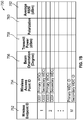
- database schemas 700, 750 may be implemented on a digital storage device as data structures.
- the data structures may include keys to identify information and information locations.
- the data structures may be aggregated to relate to one or more wireless access points 104 and wireless endpoints 102.
- Database schema 700 includes an index database entry in column 702 of the wireless endpoint 102 and associated wireless access points 104 that have been identified and analyzed or that are waiting analysis in column 704.
- Column 706 includes database entries of directional antenna orientations 402.
- transmission power database entries are stored of the signal sent from the wireless endpoint 102 corresponding with the directional antenna orientations 402.
- polarizations (circular or otherwise) are stored as database entries.
- average RSSI from the wireless access point 104 is stored as a database entry.
- Database schema 750 includes a listing 752 of the wireless endpoints 102 and the primary and secondary wireless access points 104 associated therewith pertaining to a first greatest likelihood of connection and a second greatest likelihood of connection in column 754.
- the wireless access points 104 may be associated wireless endpoints 102 through a ratio of the transmission power and the average RSSI received, as stored in columns 758 and 762. Also included is the respective directional antenna orientation 756 and the associated polarization in column 760.
- the wireless endpoints 102 disclosed herein may improve communication range. Hence, depending upon the spatial distribution of the WAPs 104 within the aircraft 100, the wireless endpoints 102 may be installed more sporadically throughout the aircraft 100. This may help to reduce the overall network design cost and aircraft weight, while maintaining the adequate performance.
Landscapes
- Engineering & Computer Science (AREA)
- Computer Networks & Wireless Communication (AREA)
- Signal Processing (AREA)
- Databases & Information Systems (AREA)
- Physics & Mathematics (AREA)
- Theoretical Computer Science (AREA)
- General Physics & Mathematics (AREA)
- General Engineering & Computer Science (AREA)
- Data Mining & Analysis (AREA)
- Astronomy & Astrophysics (AREA)
- Aviation & Aerospace Engineering (AREA)
- Mobile Radio Communication Systems (AREA)
- Radio Transmission System (AREA)
- Quality & Reliability (AREA)
- Electromagnetism (AREA)
- Radio Relay Systems (AREA)
Abstract
Description
- This application claims the benefit of Indian Patent Application Serial No.
201911041775 filed October 15, 2019 - The present disclosure relates to the art of wireless communications on aircraft. Passengers, operators and control systems may harness aircraft wireless communications to communicate onboard and offboard aircraft.
- Disclosed is a method for initializing wireless communications in an aircraft by recording database entries for wireless communications in a database schema and positioning a directional antenna associated with a wireless endpoint according to the database entries. The method includes receiving absolute wireless access point coordinates from wireless access points that define respective wireless access point positions of the wireless access points. The method includes orienting the directional antenna to orientations based on the absolute wireless access point coordinates. The method includes transmitting test signals to the respective wireless access points while the directional antenna is positioned at the orientations to generate the database entries associated with the respective wireless access point positions. The method includes orienting the directional antenna according to a first one of the database entries having a greatest likelihood to establish a first communications path between a first one of the wireless access points and the wireless endpoint. The method includes transmitting a data signal to the first one of the wireless access points with a minimum transmission power based on the database entries.
- In addition to one or more of the features described above, or as an alternative, further embodiments may include that responsive to a disconnection of the first communications path, orienting the directional antenna according to a second one of the database entries having a second greatest likelihood to establish a second communications path between a second one of the wireless access points and the wireless endpoint.
- In addition to one or more of the features described above, or as an alternative, further embodiments may include wherein the disconnection of the first communications path includes a dropped packet associated with the first communications path.
- In addition to one or more of the features described above, or as an alternative, further embodiments may include wherein the orienting the directional antenna of the wireless endpoint based on the absolute wireless access point coordinates is according to relative coordinates defined by the absolute wireless access point coordinates and absolute wireless endpoint coordinates that define a wireless endpoint position of the wireless endpoint.
- In addition to one or more of the features described above, or as an alternative, further embodiments may include wherein the orientations are all positions within an offset band having a step size that corresponds with the relative coordinates.
- In addition to one or more of the features described above, or as an alternative, further embodiments may include wherein the database entries are ratios of received signal strengths and transmission powers corresponding to the absolute wireless access point coordinates and the greatest likelihood is based on the ratios.
- In addition to one or more of the features described above, or as an alternative, further embodiments may include wherein the directional antenna is an antenna apparatus that produces ratios according to the relative coordinates such that the ratios vary based on the relative coordinates.
- In addition to one or more of the features described above, or as an alternative, further embodiments may include wherein the received signal strengths are received from the respective wireless access points as a data transmission.
- In addition to one or more of the features described above, or as an alternative, further embodiments may include wherein the test signals are defined by combinations of transmission strength and polarization that vary at the orientations.
- In addition to one or more of the features described above, or as an alternative, further embodiments may include wherein the database entries are further defined according to the polarization.
- Also disclosed is a method for positioning a directional antenna associated with a wireless endpoint according to database entries. The method includes orienting the directional antenna according to a first one of the database entries having a greatest likelihood to establish a first communications path between a first one of wireless access points and the wireless endpoint.
- In addition to one or more of the features described above, or as an alternative, further embodiments may include transmitting a data signal to the first one of the wireless access points with a minimum transmission power based on the database entries; and
In addition to one or more of the features described above, or as an alternative, further embodiments may include responsive to a disconnection of the first communications path, orienting the directional antenna according to a second one of the database entries having a second greatest likelihood to establish a second communications path between a second one of the wireless access points and the wireless endpoint. - In addition to one or more of the features described above, or as an alternative, further embodiments may include wherein the database entries are defined by a method for initializing wireless communications in an aircraft by recording the database entries for wireless communications in a database schema comprising:
- In addition to one or more of the features described above, or as an alternative, further embodiments may include that receiving absolute wireless access point coordinates from wireless access points that define respective wireless access point positions of the wireless access points;
- In addition to one or more of the features described above, or as an alternative, further embodiments may include that orienting the directional antenna to orientations based on the absolute wireless access point coordinates; and
- In addition to one or more of the features described above, or as an alternative, further embodiments may include that transmitting test signals to the respective wireless access points while the directional antenna is positioned at the orientations to generate the database entries associated with the respective wireless access point positions.
- In addition to one or more of the features described above, or as an alternative, further embodiments may include wherein the disconnection of the first communications path includes a dropped packet associated with the first communications path.
- In addition to one or more of the features described above, or as an alternative, further embodiments may include wherein the database entries are ratios of received signal strengths and transmission powers corresponding to absolute wireless access point coordinates and the greatest likelihood is based on the ratios.
- In addition to one or more of the features described above, or as an alternative, further embodiments may include wherein the directional antenna is an antenna apparatus that produces ratios according to the absolute wireless access point coordinates such that the ratios vary based on the absolute wireless access point coordinates.
- In addition to one or more of the features described above, or as an alternative, further embodiments may include wherein the received signal strengths are received from the respective wireless access points as a data transmission.
- Also disclosed is a controller program product operable to enable orientation of a directional antenna associated with a wireless endpoint on an aircraft. The controller program product includes digital storage including database entries associated with a database schema corresponding to connection likelihoods between the wireless endpoint and wireless access points. The computer program product includes controller instructions stored on the digital storage operable upon execution by a controller of the wireless endpoint to orient the directional antenna according to a first one of the database entries having a greatest likelihood to establish a first communications path between a first one of wireless access points and the wireless endpoint and transmit a data signal to the first one of the wireless access points with a minimum transmission power defined in the first one of the database entries, the controller instructions further operable upon execution by the controller to responsive to a disconnection of the first communications path, orienting the directional antenna according to a second one of the database entries having a second greatest likelihood to establish a second communications path between a second one of the wireless access points and the wireless endpoint.
- In addition to one or more of the features described above, or as an alternative, further embodiments may include wherein the disconnection of the first communications path includes a dropped packet associated with the first communications path.
- In addition to one or more of the features described above, or as an alternative, further embodiments may include wherein the database entries are ratios of received signal strengths and transmission powers corresponding to absolute wireless access point coordinates and the greatest likelihood is based on the ratios.
- In addition to one or more of the features described above, or as an alternative, further embodiments may include wherein the directional antenna is an antenna apparatus that produces ratios according to the absolute wireless access point coordinates such that the ratios vary based on the absolute wireless access point coordinates.
- The following descriptions should not be considered limiting in any way. With reference to the accompanying drawings:
-
FIG. 1 illustrates an example an aircraft having wireless communications apparatuses disposed therein; -
FIG. 2 illustrates an example architecture of a wireless communications system; -
FIG. 3 illustrates an example transfer function associated with orienting a directional antenna; -
FIG. 4 illustrates an example an example coordinate system associated with an aircraft; -
FIG. 5A illustrates an example process associated with analyzing a wireless communications system; -
FIG. 5B illustrates an example process associated with establishing communications within wireless communications system; -
FIG. 6 illustrates a process associated with wireless communications; -
FIG. 7A illustrates a database schema for recording test signal results; and -
FIG. 7B illustrates a database schema for recording highest likelihood connections. - A detailed description of one or more embodiments of the disclosed apparatus and method are presented herein by way of exemplification and not limitation with reference to the Figures.
- Looking to
FIG. 1 , a portion of anaircraft 100 is shown in accordance with one or more implementations of the present disclosure. Theaircraft 100 includes awireless endpoint 102. Theaircraft 100 may house numerouswireless endpoints 102 for a variety of functions. As one of many possible uses, thewireless endpoint 102 may be connected to sensory inputs (e.g., temperature, pressure, force) related to any number of operational inputs. Thewireless endpoint 102 may provide passenger or cargo communications. As shown, thewireless endpoint 102 includes adirectional antenna 103 and acontroller 101. Thewireless endpoint 102 may be battery powered or powered by aircraft power system. Thewireless endpoint 102 may be associated with any number ofwireless access points 104. Thedirectional antenna 103 may be an antenna apparatus configured to direct electromagnetic waves that have different transmission characteristics (e.g., RSSI) that vary based on the orientation of the antenna apparatus. Thewireless access points 104 may be configured with omnidirectional antennae, directional antennae, or combinations thereof. TheA wireless endpoint 102 may be disposed throughout theaircraft 100. As an example, thewireless endpoint 102 may be associated with a temperature sensor on the aircraft wing. Thewireless access points 104 may be dispersed throughout the aircraft on the aircraft wing and the aircraft fuselage. Thewireless endpoint 102 includes adirectional antenna 103 that improves communications with one or more of thewireless access points 104 such that thewireless endpoint 102 can reduce transmission power. Indeed, power consumption ofwireless endpoints 102 may be reduced to improve energy consumption of theaircraft 100 or batteries. - Turning to
FIG. 2 , a network architecture is shown in accordance with one or more implementations of the present disclosure. The network architecture includes thewireless endpoint 102 and wireless access points 104. Thewireless endpoint 102 includes thedirection antenna 103. It should be appreciated that thedirectional antenna 103 may be any type, including parabolic antennas, phase array antennas, and the like. Thewireless endpoint 102 may include aradio module 105 for packetization and organization of data communications. Thewireless endpoint 102 may include anorientation controller 300. As discussed with regard toFIG. 3 theorientation controller 300 may control an orientation of thedirectional antenna 103. Those versed in the art will readily appreciate that the orientation may be mechanical with regard to a parabolic antenna, electromagnetic with regard to a phased array, or another implement. As one non-limiting example, thewireless endpoint 102 is configured to communicate with thewireless access points 104 over afirst communications path 116 between a first one of thewireless access points 104 and thewireless endpoint 102. As another non-limiting example, thewireless endpoint 102 is configured to communicate with thewireless access points 104 over asecond communications path 118 between a second one of thewireless access points 104 and thewireless endpoint 102. Thewireless access points 104 may be associated with anetwork manager 110. Thenetwork manager 110 may be a router or a dynamic host configuration protocol (DHCP) server configured to establish and route communications between thewireless access points 104 and flight controls 106. The flight controls 106 may include different endpoint controllers 108 (e.g., integrated health management, prognostic health management, engine health management). - Referring to
FIG. 3 , a portion of anorientation controller 300 in accordance with one or more implementations of the present disclosure is shown. The orientation controller may be disposed on thewireless endpoint 102, in communication with thewireless endpoint 102, or a combination thereof. Theorientation controller 300 may receive absolute wireless access point coordinates 308 that define a wireless access point position respective theaircraft 100 or another point of origin. Theorientation controller 300 may receive absolute wireless endpoint coordinates 306 that define a wireless endpoint position respective theaircraft 100 or another point of origin. Theorientation controller 300 may comprise atransform 302 or computational implement that converts the absolute wireless access point coordinates 308 and absolute wireless endpoint coordinates 306 intorelative coordinates 310 for orienting thedirectional antenna 103. That is, the absolute wireless access point coordinates 308 and absolute wireless endpoint coordinates 306 may be used to determinerelative coordinates 310 that define a position of thewireless endpoint 102 with respect to respective wireless access point positions. The relative coordinates 310 may be used to determine an estimated orientation coordinates 312 of thedirectional antenna 103 infunction block 304. As such, thedirectional antenna 103 may be oriented in an angle that is directed toward one of thewireless access points 104 at a time. - Turning to
FIG. 4 , a coordinatesystem 400 with orientational angles is shown in accordance with one or more implementations of the present disclosure. As shown, coordinates are given with respect to the origin (O). The origin may be a position on theaircraft 100 for defining the absolute coordinates of thewireless endpoints 102 and the wireless access points 104. The origin may be thewireless endpoints 102 or thewireless access points 104 for determination of the relative coordinates 310. The coordinates may three-dimensional, including anx-axis 408, y-axis 406, and z-axis 404. Adirectional antenna orientation 402 of thedirectional antenna 103 corresponds withcoordinates - Referring to
FIG. 5A , portions of anexample process 500 associated with analyzing a wireless communications system in accordance with one or more implementations of the present disclosure is shown. It should be appreciated that all processes disclosed herein may include a step-by-step disclosure of the implementation and steps may be added, omitted, or rearranged as necessary. The steps may be further performed in series or in parallel. Theprocess 500 begins instep 502. Theprocess 500 may be performed during installation or manufacture. Theprocess 500 may be performed during operation or in-flight for update or confirmation. Instep 504, thewireless endpoint 102 scans to identify wireless access points 104. - A list of
wireless access points 104 is prepared instep 506. Instep 508, the firstwireless access point 104 is selected by thewireless endpoint 102. Instep 510, absolute wireless access point coordinates 308 and absolute wireless endpoint coordinates 306 may be exchanged between thewireless access point 104, and thewireless endpoint 102. It should be appreciated that thewireless access point 104, thewireless endpoint 102, or both may include predefined absolute wireless access point coordinates 308 and absolute wireless endpoint coordinates 306. Instep 512, the relative coordinates 310 may be determined bytransform 302. - In
step 514, thedirectional antenna 103 is oriented to thedirectional antenna orientation 402. Instep 516 and the following steps, test signals are sent to thewireless access points 104 including varying the power transmission level to determine a minimum transmission power required to establish communications with thewireless access point 104 without dropping packets or a communication path. Polarization of electromagnetic waves from thewireless endpoint 102 may be adjusted to left or right circular polarization, or any other polarization or strength for that matter, to determine the best communication parameters. The reflective properties of thedirectional antenna 103 may further distort polarization that may require different polarization levels to be evaluated. Thedirectional antenna 103 may be oriented within an offset band, offset from the estimated orientation coordinates 312 to determine the minimum transmission power necessary to establish thecommunications paths directional antenna orientation 402 may adjust thedirectional antenna orientation 402 within a band that includes the estimated orientation coordinates 312. The band may shift based on (RSSI) from thewireless access point 104. As an example, if the RSSI is increasing along a trajectory, acontroller 101 associated with thedirectional antenna 103 will continue in such a direction until the maximum RSSI is found. The RSSI may be sent from thewireless access points 104 as a data transmission (e.g., packets including the numerical value of the RSSI). - The
controller 101 associated with thewireless endpoint 102 may include any combination of processors, field programmable gate arrays (FPGA), or application specific integrated circuits (ASIC). Thecontroller 101 may include memory, volatile and non-volatile, operable to store machine and controller instructions from the processors and other processing mechanisms to receive, calculate, and control devices, as necessary. Machine instructions may be stored (e.g., stored instructions, stored machine instructions, stored steps) in any language or representation, including but not limited to machine code, assembly instructions, C, C++, C#, PASCAL, COBAL, PYTHON, JAVA, and RUBY to form a controller program product. It should be appreciated that any type of wired or wireless configuration is appreciated for any of the communications from thecontroller 101. Wireless protocols such as ZIGBEE, WI-FI, BLUETOOTH, or any other implement may be used. Communications may be realized through any protocol or medium known or unknown. It should be appreciated that the wireless communications disclosed herein may include any protocols (e.g., 802.11), mediums, or components for communicating. Thecontroller 101 may be associated with thedirectional antenna 103 by any number of actuators including electric motors. - In
step 518, the RSSI, transmission power, and polarization settings-along with the orientation settings-is stored as database entries, as shown inFIGs. 7A-7B . Some of the parameters or settings may be omitted and other parameters and settings may be added. - After the
wireless endpoint 102 has analyzed one or more of thewireless access points 104, thewireless endpoint 102 identifies thewireless access point 104 having the greatest likelihood to establish connection instep 520. Thewireless access point 104 having the greatest likelihood to establish connection may further be thewireless access point 104 associated with a minimum transmission power, enabling higher likelihood establishment of thecommunication paths - Referring to
FIG. 5B , anexample process 550 associated with establishing communications within wireless communications system is shown in accordance with one or more implementations of the present disclosure. Instep 552, theprocess 550 beings. Instep 554, thedirectional antenna 103 is oriented to improve transmission with a firstwireless access point 104 to establish afirst communication path 116. Instep 556, data is transmitted betweenwireless access point 104 and thewireless endpoint 102, communicating a data signal. Instep 558, thecontroller 101 or another implement determines whether a disconnection has occurred. The determination may be based on a loss of signal, dropped packets above a predetermined threshold, improper sequence numbering, or any other situation. Instep 560, thedirectional antenna 103 is oriented to improve transmission with a secondwireless access point 104 to establish asecond communication path 118 responsive to the disconnection. Instep 562, data is transmitted betweenwireless access point 104 and thewireless endpoint 102 over thesecond communication path 118. The process may continue, connecting to the highest likelihood connection based on the database entries to ensure continued communications between thewireless endpoint 102 and thewireless access point 104. - Continuing with
FIG. 6 , aprocess 600 associated with wireless communications is shown in accordance with one or more implementations of the present disclosure. Thewireless access points 104 orwireless endpoints 102 may use the process for parallel processing of access control and communications. Instep 602, theprocess 600 begins. Instep 604, if a communications path request is received, thewireless access point 104 determines whether thewireless endpoint 102 is on the access list instep 606. If thewireless endpoint 102 is on the access less instep 606, thewireless access point 104 accepts and acknowledges the communications instep 608. - In
step 610, thewireless access point 104 determines whether a communications path exists. If thecommunications paths wireless access point 104 identifies thewireless endpoint 102 instep 612. If commands are requested to be sent or received, thewireless access point 104 orwireless endpoint 102 sends the commands instep 614. Instep 616, the transmission is completed and acknowledged. - Now turning to
FIGs. 7A-7B ,database schemas database schemas wireless access points 104 andwireless endpoints 102.Database schema 700 includes an index database entry incolumn 702 of thewireless endpoint 102 and associatedwireless access points 104 that have been identified and analyzed or that are waiting analysis incolumn 704.Column 706 includes database entries ofdirectional antenna orientations 402. Incolumn 708, transmission power database entries are stored of the signal sent from thewireless endpoint 102 corresponding with thedirectional antenna orientations 402. Incolumn 710 polarizations (circular or otherwise) are stored as database entries. Incolumn 712 average RSSI from thewireless access point 104 is stored as a database entry. -
Database schema 750 includes a listing 752 of thewireless endpoints 102 and the primary and secondarywireless access points 104 associated therewith pertaining to a first greatest likelihood of connection and a second greatest likelihood of connection incolumn 754. Thewireless access points 104 may be associatedwireless endpoints 102 through a ratio of the transmission power and the average RSSI received, as stored incolumns directional antenna orientation 756 and the associated polarization incolumn 760. - Those versed in the art will appreciated that the
wireless endpoints 102 disclosed herein may improve communication range. Hence, depending upon the spatial distribution of theWAPs 104 within theaircraft 100, thewireless endpoints 102 may be installed more sporadically throughout theaircraft 100. This may help to reduce the overall network design cost and aircraft weight, while maintaining the adequate performance. - The terminology used herein is for the purpose of describing the features associated with the present disclosure and is not intended to be limiting of the present disclosure. As used herein, the singular forms "a", "an" and "the" are intended to include the plural forms as well, unless the context clearly indicates otherwise. It will be further understood that the terms "comprises" and/or "comprising," when used in this specification, specify the presence of stated features, integers, steps, operations, elements, and/or components, but do not preclude the presence or addition of one or more other features, integers, steps, operations, element components, and/or groups thereof.
- While the present disclosure has been described with reference to features and parts, it will be understood by those skilled in the art that various changes may be made, and equivalents may be substituted for elements thereof without departing from the scope of the invention as defined by the claims.
Claims (14)
- A method for initializing wireless communications in an aircraft by recording database entries for wireless communications in a database schema and positioning a directional antenna associated with a wireless endpoint according to the database entries comprising:receiving absolute wireless access point coordinates from wireless access points that define respective wireless access point positions of the wireless access points;orienting the directional antenna to orientations based on the absolute wireless access point coordinates;transmitting test signals to the respective wireless access points while the directional antenna is positioned at the orientations to generate the database entries associated with the respective wireless access point positions;orienting the directional antenna according to a first one of the database entries having a greatest likelihood to establish a first communications path between a first one of the wireless access points and the wireless endpoint; andtransmitting a data signal to the first one of the wireless access points with a minimum transmission power based on the database entries.
- The method of claim 1, further comprising responsive to a disconnection of the first communications path, orienting the directional antenna according to a second one of the database entries having a second greatest likelihood to establish a second communications path between a second one of the wireless access points and the wireless endpoint.
- The method of claim 1 or 2, wherein the orienting the directional antenna of the wireless endpoint based on the absolute wireless access point coordinates is according to relative coordinates defined by the absolute wireless access point coordinates and absolute wireless endpoint coordinates that define a wireless endpoint position of the wireless endpoint.
- The method of claim 3, wherein the orientations are all positions within an offset band having a step size that corresponds with the relative coordinates.
- The method of any preceding claim, wherein the directional antenna is an antenna apparatus that produces ratios according to the relative coordinates such that the ratios vary based on the relative coordinates.
- The method of any preceding claim, wherein the test signals are defined by combinations of transmission strength and polarization that vary at the orientations.
- The method of claim 6, wherein the database entries are further defined according to the polarization.
- A method for positioning a directional antenna associated with a wireless endpoint according to database entries comprising:orienting the directional antenna according to a first one of the database entries having a greatest likelihood to establish a first communications path between a first one of wireless access points and the wireless endpoint;transmitting a data signal to the first one of the wireless access points with a minimum transmission power based on the database entries; andresponsive to a disconnection of the first communications path, orienting the directional antenna according to a second one of the database entries having a second greatest likelihood to establish a second communications path between a second one of the wireless access points and the wireless endpoint.
- The method of claim 8, wherein the database entries are defined by a method for initializing wireless communications in an aircraft by recording the database entries for wireless communications in a database schema comprising:receiving absolute wireless access point coordinates from wireless access points that define respective wireless access point positions of the wireless access points;orienting the directional antenna to orientations based on the absolute wireless access point coordinates; andtransmitting test signals to the respective wireless access points while the directional antenna is positioned at the orientations to generate the database entries associated with the respective wireless access point positions.
- The method of any preceding claim , wherein the disconnection of the first communications path includes a dropped packet associated with the first communications path.
- The method of any preceding claim, wherein the database entries are ratios of received signal strengths and transmission powers corresponding to absolute wireless access point coordinates and the greatest likelihood is based on the ratios.
- The method of claim 11, wherein the directional antenna is an antenna apparatus that produces ratios according to the absolute wireless access point coordinates such that the ratios vary based on the absolute wireless access point coordinates.
- The method of claim 11 or 12, wherein the received signal strengths are received from the respective wireless access points as a data transmission.
- A controller program product operable to enable orientation of a directional antenna associated with a wireless endpoint on an aircraft comprising:digital storage including database entries associated with a database schema corresponding to connection likelihoods between the wireless endpoint and wireless access points; andcontroller instructions stored on the digital storage operable upon execution by a controller of the wireless endpoint to perform the method of any of claims 8 to 14.
Applications Claiming Priority (1)
| Application Number | Priority Date | Filing Date | Title |
|---|---|---|---|
| IN201911041775 | 2019-10-15 |
Publications (2)
| Publication Number | Publication Date |
|---|---|
| EP3813273A2 true EP3813273A2 (en) | 2021-04-28 |
| EP3813273A3 EP3813273A3 (en) | 2021-07-28 |
Family
ID=72943871
Family Applications (1)
| Application Number | Title | Priority Date | Filing Date |
|---|---|---|---|
| EP20202030.1A Pending EP3813273A3 (en) | 2019-10-15 | 2020-10-15 | Directional wireless communications onboard aircraft |
Country Status (2)
| Country | Link |
|---|---|
| US (1) | US11153922B2 (en) |
| EP (1) | EP3813273A3 (en) |
Family Cites Families (30)
| Publication number | Priority date | Publication date | Assignee | Title |
|---|---|---|---|---|
| US5440719A (en) | 1992-10-27 | 1995-08-08 | Cadence Design Systems, Inc. | Method simulating data traffic on network in accordance with a client/sewer paradigm |
| US8140658B1 (en) | 1999-10-06 | 2012-03-20 | Borgia/Cummins, Llc | Apparatus for internetworked wireless integrated network sensors (WINS) |
| IL134755A0 (en) | 2000-02-28 | 2001-04-30 | Terracross Ltd | Method and apparatus for high-speed generation of a priority metric for queues |
| KR20050026701A (en) * | 2002-05-07 | 2005-03-15 | 아이피알 라이센싱, 인코포레이티드 | Antenna adaptation in a time division duplexing system |
| GB2393077A (en) | 2002-09-14 | 2004-03-17 | Roke Manor Research | Aligning a directional antenna towards an access point using location information |
| US7440785B2 (en) | 2003-03-07 | 2008-10-21 | Nortel Networks Limited | Method and apparatus for enhancing link range in a wireless network using self-configurable antenna |
| US7231180B2 (en) | 2004-03-24 | 2007-06-12 | Honeywell International, Inc. | Aircraft engine sensor network using wireless sensor communication modules |
| US7120468B1 (en) | 2005-04-15 | 2006-10-10 | Texas Instruments Incorporated | System and method for steering directional antenna for wireless communications |
| US7616642B2 (en) | 2006-01-04 | 2009-11-10 | Sap Ag | Priority assignment and transmission of sensor data |
| US7616960B2 (en) | 2006-03-31 | 2009-11-10 | Sap Ag | Channel selection for wireless transmission from a remote device |
| US8917207B2 (en) | 2007-10-16 | 2014-12-23 | Livetv, Llc | Aircraft in-flight entertainment system having a multi-beam phased array antenna and associated methods |
| US8352392B2 (en) | 2007-11-28 | 2013-01-08 | The Boeing Company | Methods and system for modeling network traffic |
| WO2010033779A1 (en) | 2008-09-19 | 2010-03-25 | Delphi Technologies, Inc. | A multi-beam, polarization diversity narrow-band cognitive antenna |
| US8374601B2 (en) | 2010-01-29 | 2013-02-12 | Simmonds Precision Products, Inc. | Circularly polarized antennas for a wireless sensor system |
| KR20110138092A (en) | 2010-06-18 | 2011-12-26 | 한국전자통신연구원 | Network traffic modeling method and apparatus |
| US20120286935A1 (en) | 2011-05-10 | 2012-11-15 | Haiying Huang | Unpowered wireless sensor systems and methods |
| US9571378B2 (en) | 2011-06-28 | 2017-02-14 | The Boeing Company | Synchronized wireless data concentrator for airborne wireless sensor networks |
| US9058565B2 (en) | 2011-08-17 | 2015-06-16 | At&T Intellectual Property I, L.P. | Opportunistic crowd-based service platform |
| US8849475B1 (en) | 2012-04-04 | 2014-09-30 | The Boeing Company | Systems and method for managing sensors in a vehicle |
| US9816897B2 (en) | 2012-06-06 | 2017-11-14 | Harris Corporation | Wireless engine monitoring system and associated engine wireless sensor network |
| GB2505203B (en) | 2012-08-22 | 2017-09-13 | Ge Aviat Systems Ltd | Method for allocation of network resources in an operations network for a selected environment |
| KR101904951B1 (en) | 2013-11-13 | 2018-10-08 | 삼성전자주식회사 | Apparatus and method for searching target cell for handover in wireless communication system |
| US20150296500A1 (en) | 2014-04-15 | 2015-10-15 | Honeywell International Inc. | Radio resource management methods and systems |
| US9906425B2 (en) | 2014-07-23 | 2018-02-27 | Cisco Technology, Inc. | Selective and dynamic application-centric network measurement infrastructure |
| US9832135B2 (en) | 2014-10-23 | 2017-11-28 | Bae Systems Information And Electronic Systems Integration Inc. | Apparatus for managing data queues in a network |
| US20160196527A1 (en) | 2015-01-06 | 2016-07-07 | Falkonry, Inc. | Condition monitoring and prediction for smart logistics |
| US9948513B2 (en) | 2015-03-13 | 2018-04-17 | International Business Machines Corporation | Managing servers with quality of service assurances |
| US9888079B2 (en) | 2015-07-30 | 2018-02-06 | The Boeing Company | Method for managing messages across a controller area network |
| WO2018060950A1 (en) | 2016-09-29 | 2018-04-05 | Getsat Communications Ltd. | Methods circuits devices assemblies and systems for providing an active antenna |
| US10455445B2 (en) | 2017-06-22 | 2019-10-22 | Rosemount Aerospace Inc. | Performance optimization for avionic wireless sensor networks |
-
2019
- 2019-12-12 US US16/712,168 patent/US11153922B2/en active Active
-
2020
- 2020-10-15 EP EP20202030.1A patent/EP3813273A3/en active Pending
Also Published As
| Publication number | Publication date |
|---|---|
| US11153922B2 (en) | 2021-10-19 |
| US20210112613A1 (en) | 2021-04-15 |
| EP3813273A3 (en) | 2021-07-28 |
Similar Documents
| Publication | Publication Date | Title |
|---|---|---|
| EP3840451B1 (en) | Data transmitting device, and data transmitting method | |
| AU2019204510B2 (en) | Multi-GBPS wireless data communication system for vehicular systems | |
| EP3616022B1 (en) | Monitoring method and device | |
| US20230379043A1 (en) | Uplink beamforming between an airborne transceiver and a terrestrial transceiver | |
| EP2631989B1 (en) | Managing antennas on an access point in a wireless network | |
| US12414146B2 (en) | Scheduling method for beamforming and network entity | |
| JP7156464B2 (en) | Vehicles and Programs | |
| US20160365917A1 (en) | Aircraft communications during different phases of flight | |
| CN109495153B (en) | Heterogeneous network, mobile device and method for beam training and tracking | |
| US11153922B2 (en) | Directional wireless communications onboard aircraft | |
| KR101798105B1 (en) | Orbital Angular Momentum Antenna Pointing Alignment Apparatus | |
| CN110858781B (en) | Measuring method and device for millimeter wave signal | |
| CN108900232A (en) | A kind of method, apparatus and electronic equipment of adaptive beamforming | |
| US12075284B2 (en) | Method and system for managing orientation of consumer premise equipment | |
| JP2019068284A (en) | Control arrangement | |
| CN111372195A (en) | Method, device and storage medium for location tracking of mobile terminal in mobile communication network | |
| KR20250114932A (en) | Device and method for performing joint communication and sensing operations using various signals in a wireless communication system | |
| CN120303884A (en) | Apparatus and method for channel estimation in IRS-assisted wireless networks | |
| EP4557873A1 (en) | Electronic device for supporting multi-link operation, and operation method thereof | |
| JP5366191B2 (en) | Radio device and antenna switching method | |
| KR20250019309A (en) | Method and Apparatus for Providing Communication Service in Mobile Communication System cooperating with UAS | |
| CN112969156B (en) | Unmanned aerial vehicle and communication method, command and control station, intelligence single receiving station, reconnaissance system | |
| CN115355907A (en) | Autonomous navigation system and method based on millimeter wave sensing integrated unmanned equipment | |
| KR20220037279A (en) | Electronic device supporting wireless communication for a vehicle and operation method of the electronic device | |
| US12442887B2 (en) | Method and system for radio transmission of data related to a production installation |
Legal Events
| Date | Code | Title | Description |
|---|---|---|---|
| PUAI | Public reference made under article 153(3) epc to a published international application that has entered the european phase |
Free format text: ORIGINAL CODE: 0009012 |
|
| STAA | Information on the status of an ep patent application or granted ep patent |
Free format text: STATUS: THE APPLICATION HAS BEEN PUBLISHED |
|
| AK | Designated contracting states |
Kind code of ref document: A2 Designated state(s): AL AT BE BG CH CY CZ DE DK EE ES FI FR GB GR HR HU IE IS IT LI LT LU LV MC MK MT NL NO PL PT RO RS SE SI SK SM TR |
|
| AX | Request for extension of the european patent |
Extension state: BA ME |
|
| PUAL | Search report despatched |
Free format text: ORIGINAL CODE: 0009013 |
|
| AK | Designated contracting states |
Kind code of ref document: A3 Designated state(s): AL AT BE BG CH CY CZ DE DK EE ES FI FR GB GR HR HU IE IS IT LI LT LU LV MC MK MT NL NO PL PT RO RS SE SI SK SM TR |
|
| RIC1 | Information provided on ipc code assigned before grant |
Ipc: H04B 7/185 20060101AFI20210624BHEP |
|
| STAA | Information on the status of an ep patent application or granted ep patent |
Free format text: STATUS: REQUEST FOR EXAMINATION WAS MADE |
|
| 17P | Request for examination filed |
Effective date: 20220128 |
|
| RBV | Designated contracting states (corrected) |
Designated state(s): AL AT BE BG CH CY CZ DE DK EE ES FI FR GB GR HR HU IE IS IT LI LT LU LV MC MK MT NL NO PL PT RO RS SE SI SK SM TR |
|
| STAA | Information on the status of an ep patent application or granted ep patent |
Free format text: STATUS: EXAMINATION IS IN PROGRESS |
|
| 17Q | First examination report despatched |
Effective date: 20230524 |