EP3813250B1 - Vibration suppression method for servo motor and load multi-stage transmission system - Google Patents
Vibration suppression method for servo motor and load multi-stage transmission system Download PDFInfo
- Publication number
- EP3813250B1 EP3813250B1 EP19820593.2A EP19820593A EP3813250B1 EP 3813250 B1 EP3813250 B1 EP 3813250B1 EP 19820593 A EP19820593 A EP 19820593A EP 3813250 B1 EP3813250 B1 EP 3813250B1
- Authority
- EP
- European Patent Office
- Prior art keywords
- vibration
- frequency
- parameter
- variable
- fixed
- Prior art date
- Legal status (The legal status is an assumption and is not a legal conclusion. Google has not performed a legal analysis and makes no representation as to the accuracy of the status listed.)
- Active
Links
Images

Classifications
-
- H—ELECTRICITY
- H02—GENERATION; CONVERSION OR DISTRIBUTION OF ELECTRIC POWER
- H02P—CONTROL OR REGULATION OF ELECTRIC MOTORS, ELECTRIC GENERATORS OR DYNAMO-ELECTRIC CONVERTERS; CONTROLLING TRANSFORMERS, REACTORS OR CHOKE COILS
- H02P21/00—Arrangements or methods for the control of electric machines by vector control, e.g. by control of field orientation
- H02P21/05—Arrangements or methods for the control of electric machines by vector control, e.g. by control of field orientation specially adapted for damping motor oscillations, e.g. for reducing hunting
-
- F—MECHANICAL ENGINEERING; LIGHTING; HEATING; WEAPONS; BLASTING
- F16—ENGINEERING ELEMENTS AND UNITS; GENERAL MEASURES FOR PRODUCING AND MAINTAINING EFFECTIVE FUNCTIONING OF MACHINES OR INSTALLATIONS; THERMAL INSULATION IN GENERAL
- F16F—SPRINGS; SHOCK-ABSORBERS; MEANS FOR DAMPING VIBRATION
- F16F15/00—Suppression of vibrations in systems; Means or arrangements for avoiding or reducing out-of-balance forces, e.g. due to motion
-
- F—MECHANICAL ENGINEERING; LIGHTING; HEATING; WEAPONS; BLASTING
- F16—ENGINEERING ELEMENTS AND UNITS; GENERAL MEASURES FOR PRODUCING AND MAINTAINING EFFECTIVE FUNCTIONING OF MACHINES OR INSTALLATIONS; THERMAL INSULATION IN GENERAL
- F16F—SPRINGS; SHOCK-ABSORBERS; MEANS FOR DAMPING VIBRATION
- F16F15/00—Suppression of vibrations in systems; Means or arrangements for avoiding or reducing out-of-balance forces, e.g. due to motion
- F16F15/002—Suppression of vibrations in systems; Means or arrangements for avoiding or reducing out-of-balance forces, e.g. due to motion characterised by the control method or circuitry
-
- B—PERFORMING OPERATIONS; TRANSPORTING
- B65—CONVEYING; PACKING; STORING; HANDLING THIN OR FILAMENTARY MATERIAL
- B65G—TRANSPORT OR STORAGE DEVICES, e.g. CONVEYORS FOR LOADING OR TIPPING, SHOP CONVEYOR SYSTEMS OR PNEUMATIC TUBE CONVEYORS
- B65G43/00—Control devices, e.g. for safety, warning or fault-correcting
- B65G43/02—Control devices, e.g. for safety, warning or fault-correcting detecting dangerous physical condition of load carriers, e.g. for interrupting the drive in the event of overheating
-
- G—PHYSICS
- G05—CONTROLLING; REGULATING
- G05B—CONTROL OR REGULATING SYSTEMS IN GENERAL; FUNCTIONAL ELEMENTS OF SUCH SYSTEMS; MONITORING OR TESTING ARRANGEMENTS FOR SUCH SYSTEMS OR ELEMENTS
- G05B19/00—Program-control systems
- G05B19/02—Program-control systems electric
- G05B19/18—Numerical control [NC], i.e. automatically operating machines, in particular machine tools, e.g. in a manufacturing environment, so as to execute positioning, movement or co-ordinated operations by means of program data in numerical form
- G05B19/404—Numerical control [NC], i.e. automatically operating machines, in particular machine tools, e.g. in a manufacturing environment, so as to execute positioning, movement or co-ordinated operations by means of program data in numerical form characterised by control arrangements for compensation, e.g. for backlash, overshoot, tool offset, tool wear, temperature, machine construction errors, load, inertia
-
- H—ELECTRICITY
- H02—GENERATION; CONVERSION OR DISTRIBUTION OF ELECTRIC POWER
- H02P—CONTROL OR REGULATION OF ELECTRIC MOTORS, ELECTRIC GENERATORS OR DYNAMO-ELECTRIC CONVERTERS; CONTROLLING TRANSFORMERS, REACTORS OR CHOKE COILS
- H02P23/00—Arrangements or methods for the control of AC motors characterised by a control method other than vector control
- H02P23/04—Arrangements or methods for the control of AC motors characterised by a control method other than vector control specially adapted for damping motor oscillations, e.g. for reducing hunting
-
- H—ELECTRICITY
- H02—GENERATION; CONVERSION OR DISTRIBUTION OF ELECTRIC POWER
- H02P—CONTROL OR REGULATION OF ELECTRIC MOTORS, ELECTRIC GENERATORS OR DYNAMO-ELECTRIC CONVERTERS; CONTROLLING TRANSFORMERS, REACTORS OR CHOKE COILS
- H02P29/00—Arrangements for regulating or controlling electric motors, appropriate for both AC and DC motors
- H02P29/02—Providing protection against overload without automatic interruption of supply
- H02P29/024—Detecting a fault condition, e.g. short circuit, locked rotor, open circuit or loss of load
- H02P29/028—Detecting a fault condition, e.g. short circuit, locked rotor, open circuit or loss of load the motor continuing operation despite the fault condition, e.g. eliminating, compensating for or remedying the fault
-
- H—ELECTRICITY
- H02—GENERATION; CONVERSION OR DISTRIBUTION OF ELECTRIC POWER
- H02P—CONTROL OR REGULATION OF ELECTRIC MOTORS, ELECTRIC GENERATORS OR DYNAMO-ELECTRIC CONVERTERS; CONTROLLING TRANSFORMERS, REACTORS OR CHOKE COILS
- H02P29/00—Arrangements for regulating or controlling electric motors, appropriate for both AC and DC motors
- H02P29/50—Reduction of harmonics
-
- F—MECHANICAL ENGINEERING; LIGHTING; HEATING; WEAPONS; BLASTING
- F16—ENGINEERING ELEMENTS AND UNITS; GENERAL MEASURES FOR PRODUCING AND MAINTAINING EFFECTIVE FUNCTIONING OF MACHINES OR INSTALLATIONS; THERMAL INSULATION IN GENERAL
- F16F—SPRINGS; SHOCK-ABSORBERS; MEANS FOR DAMPING VIBRATION
- F16F2228/00—Functional characteristics, e.g. variability, frequency-dependence
- F16F2228/04—Frequency effects
-
- F—MECHANICAL ENGINEERING; LIGHTING; HEATING; WEAPONS; BLASTING
- F16—ENGINEERING ELEMENTS AND UNITS; GENERAL MEASURES FOR PRODUCING AND MAINTAINING EFFECTIVE FUNCTIONING OF MACHINES OR INSTALLATIONS; THERMAL INSULATION IN GENERAL
- F16F—SPRINGS; SHOCK-ABSORBERS; MEANS FOR DAMPING VIBRATION
- F16F2230/00—Purpose; Design features
- F16F2230/18—Control arrangements
-
- G—PHYSICS
- G05—CONTROLLING; REGULATING
- G05B—CONTROL OR REGULATING SYSTEMS IN GENERAL; FUNCTIONAL ELEMENTS OF SUCH SYSTEMS; MONITORING OR TESTING ARRANGEMENTS FOR SUCH SYSTEMS OR ELEMENTS
- G05B2219/00—Program-control systems
- G05B2219/30—Nc systems
- G05B2219/39—Robotics, robotics to robotics hand
- G05B2219/39195—Control, avoid oscillation, vibration due to low rigidity
Definitions
- the present invention relates to a vibration suppression method for a servo controller, and specifically to a vibration suppression method for a servo motor and a load multistage drive system.
- a servo control system is widely applied to industrial automation scenarios by virtue of its relatively high dynamic response and control precision.
- the servo control system is prone to vibration during running because of a non-rigid coupling between a servo motor and a load.
- Use of a vibration suppression filter (usually a notch filter) in a control loop of the servo controller may well suppress the vibration.
- a vibration frequency of each stage of drive mechanism is related to inertia of both ends of the drive mechanism and rigidity of the drive mechanism. If the inertia or the drive rigidity varies during movement, the vibration frequency may also change correspondingly.
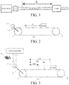
- a lead screw drive system shown in FIG. 1 has a fixed vibration frequency and a variable vibration frequency.
- a coupling is at a first stage of drive, and inertia of both ends of the coupling and rigidity of the coupling remain unchanged, so that its vibration frequency is fixed.
- Driving, by a lead screw, a load to move is at a second stage of drive, and because rigidity of the lead screw is related to a load position L, its vibration frequency is related to L.
- a last stage of drive mechanism driving the load has a vibration frequency related to the load position, and vibration frequencies of drive mechanisms other than the last stage of drive mechanism are fixed.
- the methods are commonly characterized in that the vibration frequency in the control loop can be filtered out only when a frequency parameter of the vibration suppression filter is set correctly, so as to suppress the vibration.
- the fixed parameter setting method does not consider a case that a vibration frequency varies during running. Consequently, the method is only applicable to a simple single-stage drive system.
- the adaptive parameter setting method is to measure the vibration frequency online and adjust the frequency parameter of the vibration suppression filter in real time during running. The method is relatively complex and its performance depends on accuracy of the online vibration frequency measurement.
- JP 6 198393 B2 describes a contact type three-dimensional shape measuring apparatus.
- US 2007/061047 A1 relates to a method of automatically setting by vibration suppression filter.
- the technical problem to be resolved in the present invention is to overcome defects existing in the prior art and provide a vibration suppression method for a servo motor and a load multistage drive system.
- Fixed vibration frequencies and a vibration frequency varying with a load position in a multistage drive system are measured by using an offline method, and the varied vibration frequencies are made into a two-dimensional table related to the load positions.
- the fixed vibration frequencies are eliminated by using fixed-frequency parameter vibration suppression filters; and the varied vibration frequencies are eliminated by using a variable-frequency parameter vibration suppression filter, and the vibration frequencies are obtained in real time according to the load positions and the two-dimensional table by using a linear interpolation method.
- the basic idea of the present invention is to aim at a number N of fixed vibration frequencies and one vibration frequency varying with a load position that exist in the multistage drive mechanism.
- a number N+1 of vibration suppression filters are adopted in the present invention, and each filter is configured to eliminate a corresponding vibration frequency.
- the fixed vibration frequencies are eliminated by using fixed-frequency parameter vibration suppression filters; and the vibration frequency varying with the load position is eliminated by using a variable- frequency parameter vibration suppression filter.
- the present invention provides a vibration suppression method for a servo motor and a load multistage drive system as specified in claim 1, including following steps:
- fixed vibration frequencies and a vibration frequency varying with a load position in a multistage drive system are measured by using an offline method, and the varied vibration frequencies are made into a two-dimensional table related to the load positions.
- the fixed vibration frequencies are eliminated by using fixed-frequency parameter vibration suppression filters.
- the varied vibration frequencies are eliminated by using a variable-frequency parameter vibration suppression filter, and the vibration frequencies are obtained in real time according to the load positions and the two-dimensional table by using a linear interpolation method.
- the method in the present invention is easy to implement, and can measure the frequency accurately and take both fixed and variable vibration frequencies into account.
- FIG. 2 shows a typical belt drive system, and the system has a fixed vibration frequency and a variable vibration frequency.
- a drive mechanism formed by the synchronizing wheel 1, a synchronizing wheel 2, and a belt has a fixed vibration frequency.
- a drive mechanism formed by the synchronizing wheel 1, the belt 5 and a load has a variable vibration frequency related to a load position.
- a vibration suppression filter adopted in this embodiment is a standard notch filter, a transfer function of which is as follows.
- G s s 2 + ⁇ n 2 s 2 + 2 ⁇ n s + ⁇ n 2
- ⁇ n is a center frequency of the notch filter
- ⁇ is a bandwidth of the notch filter
- Step 1 Measuring vibration frequencies.
- a load is stopped at positions of L1, L2, and L3 respectively, and a servo controller is used to give a given torque 6 with relatively rich frequency components, and detect a feedback speed 7 of the motor.
- Fourier transform is performed on the feedback speed, and an amplitude-frequency curve thereof is drawn, as shown in FIG. 4 .
- FIG. 5 shows a relationship between the measured vibration frequencies and the positions.
- Step 2 Setting a notch filter with a fixed center frequency.
- a notch filter with a fixed center frequency is adopted.
- the center frequency thereof is set to the fixed vibration frequency F0.
- Step 2 Setting a notch filter with a variable center frequency.
- a notch filter with a variable center frequency is adopted.
- a vibration frequency F of a load position L is calculated according to the position by using a linear interpolation method; and the vibration frequency is set to a center frequency of the notch filter.
- the fixed-parameter vibration suppression filter and the variable-parameter vibration suppression filter are used respectively, and do not affect each other.
- the vibration frequency is measured in an offline manner.
- the implementation is relatively simple and may obtain a more accurate vibration frequency.
- a servo controller is used to give a given torque with relatively rich frequency components, and detect a feedback speed of the motor, and no extra measurement device is required.
- the variable vibration frequencies are made into a two-dimensional table, and when the system is running, vibration frequencies of different load positions are obtained by using a table look-up method and a linear interpolation method. Therefore, the method is applicable to a multistage drive system with variable vibration frequencies.
- a number N+1 of vibration frequencies in the multistage drive system are eliminated by using a number N+1 of vibration suppression filters.
- a number N of fixed-parameter vibration suppression filters eliminate N fixed vibration frequencies; and one variable-parameter vibration suppression filter eliminates one variable vibration frequency.
- frequency parameters of the fixed-parameter vibration suppression filters are unchanged, and vibration frequencies of different load positions are calculated according to the frequency parameter of the variable-parameter vibration suppression filter by using a linear interpolation method.
Landscapes
- Engineering & Computer Science (AREA)
- General Engineering & Computer Science (AREA)
- Power Engineering (AREA)
- Physics & Mathematics (AREA)
- Aviation & Aerospace Engineering (AREA)
- Mechanical Engineering (AREA)
- Acoustics & Sound (AREA)
- Human Computer Interaction (AREA)
- Manufacturing & Machinery (AREA)
- General Physics & Mathematics (AREA)
- Automation & Control Theory (AREA)
- Control Of Electric Motors In General (AREA)
- Feedback Control In General (AREA)
- Control Of Position Or Direction (AREA)
Description
- The present invention relates to a vibration suppression method for a servo controller, and specifically to a vibration suppression method for a servo motor and a load multistage drive system.
- In recent years, a servo control system is widely applied to industrial automation scenarios by virtue of its relatively high dynamic response and control precision. In terms of mechanical connection, the servo control system is prone to vibration during running because of a non-rigid coupling between a servo motor and a load. Use of a vibration suppression filter (usually a notch filter) in a control loop of the servo controller may well suppress the vibration.
- In most application scenarios, there are a plurality of stages of drive mechanisms between the servo motor and the load. Vibrations may be generated between the drive mechanisms. A vibration frequency of each stage of drive mechanism is related to inertia of both ends of the drive mechanism and rigidity of the drive mechanism. If the inertia or the drive rigidity varies during movement, the vibration frequency may also change correspondingly.
- A lead screw drive system shown in
FIG. 1 has a fixed vibration frequency and a variable vibration frequency. A coupling is at a first stage of drive, and inertia of both ends of the coupling and rigidity of the coupling remain unchanged, so that its vibration frequency is fixed. Driving, by a lead screw, a load to move is at a second stage of drive, and because rigidity of the lead screw is related to a load position L, its vibration frequency is related to L. - Extension is made to a multistage drive system, a last stage of drive mechanism driving the load has a vibration frequency related to the load position, and vibration frequencies of drive mechanisms other than the last stage of drive mechanism are fixed.
- There are many vibration suppression methods for general-purpose servo products. The methods are commonly characterized in that the vibration frequency in the control loop can be filtered out only when a frequency parameter of the vibration suppression filter is set correctly, so as to suppress the vibration. Currently, there are two methods for setting the frequency parameter of the vibration suppression filter: setting a fixed parameter and setting an adaptive parameter. The fixed parameter setting method does not consider a case that a vibration frequency varies during running. Consequently, the method is only applicable to a simple single-stage drive system. The adaptive parameter setting method is to measure the vibration frequency online and adjust the frequency parameter of the vibration suppression filter in real time during running. The method is relatively complex and its performance depends on accuracy of the online vibration frequency measurement.
-
US 2007/205740 A1 describes a method of automatically setting the vibration suppression filter. -
JP 6 198393 B2 -
US 2007/061047 A1 relates to a method of automatically setting by vibration suppression filter. - The technical problem to be resolved in the present invention is to overcome defects existing in the prior art and provide a vibration suppression method for a servo motor and a load multistage drive system. Fixed vibration frequencies and a vibration frequency varying with a load position in a multistage drive system are measured by using an offline method, and the varied vibration frequencies are made into a two-dimensional table related to the load positions. The fixed vibration frequencies are eliminated by using fixed-frequency parameter vibration suppression filters; and the varied vibration frequencies are eliminated by using a variable-frequency parameter vibration suppression filter, and the vibration frequencies are obtained in real time according to the load positions and the two-dimensional table by using a linear interpolation method.
- The basic idea of the present invention is to aim at a number N of fixed vibration frequencies and one vibration frequency varying with a load position that exist in the multistage drive mechanism. a number N+1 of vibration suppression filters are adopted in the present invention, and each filter is configured to eliminate a corresponding vibration frequency. The fixed vibration frequencies are eliminated by using fixed-frequency parameter vibration suppression filters; and the vibration frequency varying with the load position is eliminated by using a variable- frequency parameter vibration suppression filter.
- The present invention provides a vibration suppression method for a servo motor and a load multistage drive system as specified in
claim 1, including following steps: - Step 1: measuring vibration frequencies
Measuring vibration frequencies of stages of drive mechanisms offline, including a number N of fixed vibration frequencies and one variable vibration frequency. For measurement of the variable vibration frequency, successively stopping a load at different positions, recording the load positions and measuring vibration frequencies, and drawing a two-dimensional table according to a relationship between the vibration frequencies and the load positions; - Step 2: setting frequency parameters of fixed-parameter vibration suppression filters
Selecting a number N of fixed-parameter vibration suppression filters, frequency parameters of which respectively correspond to a number N of fixed vibration frequencies measured in thestep 1; and - Step 3: setting a frequency parameter of a variable-parameter vibration suppression filter
Selecting a variable-parameter vibration suppression filter. During movement, calculating, according to a load position and the two-dimensional table drawn in thestep 1, a vibration frequency of the position by using a linear interpolation method. Setting the vibration frequency to a frequency parameter of the variable-parameter vibration suppression filter. - In the present invention, fixed vibration frequencies and a vibration frequency varying with a load position in a multistage drive system are measured by using an offline method, and the varied vibration frequencies are made into a two-dimensional table related to the load positions. The fixed vibration frequencies are eliminated by using fixed-frequency parameter vibration suppression filters. The varied vibration frequencies are eliminated by using a variable-frequency parameter vibration suppression filter, and the vibration frequencies are obtained in real time according to the load positions and the two-dimensional table by using a linear interpolation method. The method in the present invention is easy to implement, and can measure the frequency accurately and take both fixed and variable vibration frequencies into account.
-
-
FIG. 1 shows a lead screw drive system; -
FIG. 2 shows a belt pulley drive system; -
FIG. 3 is a schematic diagram of measuring a vibration frequency of a belt pulley drive system; -
FIG. 4 shows an amplitude-frequency curve of a belt pulley drive system; and -
FIG. 5 shows a relationship between a vibration frequency and a load position. -
FIG. 2 shows a typical belt drive system, and the system has a fixed vibration frequency and a variable vibration frequency. There is arigid coupling 4 and no vibration between aservo motor 3 and a synchronizingwheel 1. A drive mechanism formed by the synchronizingwheel 1, a synchronizing wheel 2, and a belt has a fixed vibration frequency. A drive mechanism formed by the synchronizingwheel 1, thebelt 5 and a load has a variable vibration frequency related to a load position. - A vibration suppression filter adopted in this embodiment is a standard notch filter, a transfer function of which is as follows.

- Wherein, ωn is a center frequency of the notch filter, and ζ is a bandwidth of the notch filter.
- Implementation steps are as follows:
Step 1: Measuring vibration frequencies. - As shown in
FIG. 3 , a load is stopped at positions of L1, L2, and L3 respectively, and a servo controller is used to give a giventorque 6 with relatively rich frequency components, and detect a feedback speed 7 of the motor. Fourier transform is performed on the feedback speed, and an amplitude-frequency curve thereof is drawn, as shown inFIG. 4 . There is a fixed vibration frequency F0 and variable vibration frequencies F1, F2, and F3 in the figure. Vibration frequencies of more positions may be measured by repeating this step, and a relationship between the variable vibration frequencies and the positions is made into a two-dimensional table.FIG. 5 shows a relationship between the measured vibration frequencies and the positions. - Step 2: Setting a notch filter with a fixed center frequency.
- A notch filter with a fixed center frequency is adopted. The center frequency thereof is set to the fixed vibration frequency F0.
- Step 2: Setting a notch filter with a variable center frequency.
- A notch filter with a variable center frequency is adopted. During movement, a vibration frequency F of a load position L is calculated according to the position by using a linear interpolation method; and the vibration frequency is set to a center frequency of the notch filter.
- According to the method of the present invention, the fixed-parameter vibration suppression filter and the variable-parameter vibration suppression filter are used respectively, and do not affect each other. The vibration frequency is measured in an offline manner. The implementation is relatively simple and may obtain a more accurate vibration frequency. When measuring the vibration frequency discretely, only a servo controller is used to give a given torque with relatively rich frequency components, and detect a feedback speed of the motor, and no extra measurement device is required. The variable vibration frequencies are made into a two-dimensional table, and when the system is running, vibration frequencies of different load positions are obtained by using a table look-up method and a linear interpolation method. Therefore, the method is applicable to a multistage drive system with variable vibration frequencies.
- A number N+1 of vibration frequencies in the multistage drive system are eliminated by using a number N+1 of vibration suppression filters. a number N of fixed-parameter vibration suppression filters eliminate N fixed vibration frequencies; and one variable-parameter vibration suppression filter eliminates one variable vibration frequency. During online running, frequency parameters of the fixed-parameter vibration suppression filters are unchanged, and vibration frequencies of different load positions are calculated according to the frequency parameter of the variable-parameter vibration suppression filter by using a linear interpolation method.
Claims (1)
- A vibration suppression method for a servo motor (3) and a load multistage drive system,
characterized by:step 1: measuring vibration frequencies
bymeasuring vibration frequencies of stages of drive mechanisms offline, wherein the vibration frequencies comprise a number N of fixed vibration frequencies and one variable vibration frequency; and bymeasuring the variable vibration frequency by successively stopping a load at different positions, recording load positions and measuring vibration frequencies, and drawing a two-dimensional table according to a relationship between the vibration frequencies and the load positions;step 2: setting frequency parameters of fixed-parameter vibration suppression filters,
by selecting a number N of fixed-parameter vibration suppression filters, wherein frequency parameters of which respectively correspond to a number N of fixed vibration frequencies measured in the step 1; andstep 3: setting a frequency parameter of a variable-parameter vibration suppression filter,
byselecting a variable-parameter vibration suppression filter; during movement, calculating a vibration frequency of the position by using a linear interpolation method, according to the load positions and the two-dimensional table drawn in the step 1; and bysetting the vibration frequency to a frequency parameter of the variable-parameter vibration suppression filter.
Applications Claiming Priority (2)
| Application Number | Priority Date | Filing Date | Title |
|---|---|---|---|
| CN201810606309.3A CN108775373B (en) | 2018-06-13 | 2018-06-13 | Vibration suppression method for servo motor and load multistage transmission system |
| PCT/CN2019/086538 WO2019237868A1 (en) | 2018-06-13 | 2019-05-13 | Vibration suppression method for servo motor and load multi-stage transmission system |
Publications (3)
| Publication Number | Publication Date |
|---|---|
| EP3813250A1 EP3813250A1 (en) | 2021-04-28 |
| EP3813250A4 EP3813250A4 (en) | 2021-04-28 |
| EP3813250B1 true EP3813250B1 (en) | 2022-07-06 |
Family
ID=64026018
Family Applications (1)
| Application Number | Title | Priority Date | Filing Date |
|---|---|---|---|
| EP19820593.2A Active EP3813250B1 (en) | 2018-06-13 | 2019-05-13 | Vibration suppression method for servo motor and load multi-stage transmission system |
Country Status (4)
| Country | Link |
|---|---|
| US (1) | US11913512B2 (en) |
| EP (1) | EP3813250B1 (en) |
| CN (1) | CN108775373B (en) |
| WO (1) | WO2019237868A1 (en) |
Families Citing this family (2)
| Publication number | Priority date | Publication date | Assignee | Title |
|---|---|---|---|---|
| CN108775373B (en) | 2018-06-13 | 2019-12-10 | 南京埃斯顿自动化股份有限公司 | Vibration suppression method for servo motor and load multistage transmission system |
| CN115793729B (en) * | 2023-01-31 | 2023-04-28 | 合肥安迅精密技术有限公司 | Bandwidth compensation method and system based on position and chip mounter |
Family Cites Families (14)
| Publication number | Priority date | Publication date | Assignee | Title |
|---|---|---|---|---|
| US6507165B2 (en) * | 2000-02-10 | 2003-01-14 | Fanuc Ltd. | Controller for machine |
| CN1408933A (en) * | 2001-09-24 | 2003-04-09 | 合肥荣事达集团有限责任公司 | Variable-frequency control method for vibration of washing machine |
| JP4367041B2 (en) | 2003-07-18 | 2009-11-18 | 富士電機システムズ株式会社 | Machine control device |
| JP2005092297A (en) * | 2003-09-12 | 2005-04-07 | Yaskawa Electric Corp | Automatic setting method of vibration suppression filter |
| JP4720744B2 (en) * | 2004-06-16 | 2011-07-13 | 株式会社安川電機 | Servo control device |
| DE112008000194B4 (en) | 2007-01-17 | 2022-02-24 | Panasonic Corporation | Servo motor control device and control method |
| CN101576752A (en) * | 2009-06-15 | 2009-11-11 | 南京航空航天大学 | Active vibration absorber with flexible structure and control method thereof |
| CN103270692B (en) | 2010-12-20 | 2016-01-20 | 三菱电机株式会社 | motor control unit |
| JP6198393B2 (en) * | 2012-12-28 | 2017-09-20 | キヤノン株式会社 | Contact type three-dimensional shape measuring apparatus and probe control method |
| JP6118988B2 (en) * | 2013-04-09 | 2017-04-26 | パナソニックIpマネジメント株式会社 | Motor drive device |
| JP6107689B2 (en) * | 2014-02-05 | 2017-04-05 | トヨタ自動車株式会社 | vehicle |
| CN204692445U (en) * | 2015-06-16 | 2015-10-07 | 广东工业大学 | Frequency-adjustable compound vibration-damper |
| CN105805224B (en) * | 2016-05-18 | 2017-09-15 | 南京尚爱机械制造有限公司 | A kind of belt vibration damping device |
| CN108775373B (en) | 2018-06-13 | 2019-12-10 | 南京埃斯顿自动化股份有限公司 | Vibration suppression method for servo motor and load multistage transmission system |
-
2018
- 2018-06-13 CN CN201810606309.3A patent/CN108775373B/en active Active
-
2019
- 2019-05-13 US US17/058,139 patent/US11913512B2/en active Active
- 2019-05-13 WO PCT/CN2019/086538 patent/WO2019237868A1/en not_active Ceased
- 2019-05-13 EP EP19820593.2A patent/EP3813250B1/en active Active
Also Published As
| Publication number | Publication date |
|---|---|
| CN108775373B (en) | 2019-12-10 |
| US11913512B2 (en) | 2024-02-27 |
| WO2019237868A1 (en) | 2019-12-19 |
| US20210199173A1 (en) | 2021-07-01 |
| EP3813250A1 (en) | 2021-04-28 |
| CN108775373A (en) | 2018-11-09 |
| EP3813250A4 (en) | 2021-04-28 |
Similar Documents
| Publication | Publication Date | Title |
|---|---|---|
| EP2571159B1 (en) | Motor control apparatus | |
| US10108177B2 (en) | Control parameter adjustment device | |
| US8538582B2 (en) | Robot and noise removing method for the robot | |
| JP6316323B2 (en) | Motor control device | |
| WO2014167852A1 (en) | Motor drive device | |
| JP5490335B1 (en) | Frequency response measuring device | |
| US11913512B2 (en) | Vibration suppression method for servo motor and load multistage drive system | |
| CN108431704A (en) | The determination of the rigidity of the power train of machine, particularly lathe or production machine | |
| US20140217952A1 (en) | Position Control Apparatus | |
| JP6118988B2 (en) | Motor drive device | |
| JP5469949B2 (en) | Electric machine control device | |
| CN108333935B (en) | Precise debugging method and system based on second-order notch filter | |
| KR20190062096A (en) | Positioning control device of an actuator including a wave gear device by fully closed-loop type control combined with state observer | |
| US20250244738A1 (en) | Servo adjustment method of motor driving device, program, and servo adjustment device for motor driving device | |
| KR20230021322A (en) | Method for estimating parameter of mechanical model for servo motor and system for controlling motor with Kalman filter using the same | |
| US20140123757A1 (en) | Method for measuring mechanical resonance frequency using servo driver | |
| CN107272576B (en) | Method for measuring frequency characteristics in feed shaft control device | |
| US20250112573A1 (en) | Motor Control Device and Method for Automatic Adjustment Thereof | |
| CN113031530B (en) | Robot control method, robot control device and robot | |
| JP2020027366A (en) | Motor control device | |
| JPWO2018073873A1 (en) | Servo control device | |
| CN115629627B (en) | Load end torque fluctuation suppression method, electronic device and storage medium | |
| CN118092174B (en) | A five-axis machine tool auxiliary method and system for intelligently configuring drive parameters |
Legal Events
| Date | Code | Title | Description |
|---|---|---|---|
| STAA | Information on the status of an ep patent application or granted ep patent |
Free format text: STATUS: THE INTERNATIONAL PUBLICATION HAS BEEN MADE |
|
| PUAI | Public reference made under article 153(3) epc to a published international application that has entered the european phase |
Free format text: ORIGINAL CODE: 0009012 |
|
| STAA | Information on the status of an ep patent application or granted ep patent |
Free format text: STATUS: REQUEST FOR EXAMINATION WAS MADE |
|
| 17P | Request for examination filed |
Effective date: 20201223 |
|
| A4 | Supplementary search report drawn up and despatched |
Effective date: 20210325 |
|
| AK | Designated contracting states |
Kind code of ref document: A1 Designated state(s): AL AT BE BG CH CY CZ DE DK EE ES FI FR GB GR HR HU IE IS IT LI LT LU LV MC MK MT NL NO PL PT RO RS SE SI SK SM TR |
|
| AX | Request for extension of the european patent |
Extension state: BA ME |
|
| DAV | Request for validation of the european patent (deleted) | ||
| DAX | Request for extension of the european patent (deleted) | ||
| GRAP | Despatch of communication of intention to grant a patent |
Free format text: ORIGINAL CODE: EPIDOSNIGR1 |
|
| STAA | Information on the status of an ep patent application or granted ep patent |
Free format text: STATUS: GRANT OF PATENT IS INTENDED |
|
| RIC1 | Information provided on ipc code assigned before grant |
Ipc: F16F 15/00 20060101ALN20220307BHEP Ipc: H02P 29/50 20160101ALI20220307BHEP Ipc: H02P 29/028 20160101ALI20220307BHEP Ipc: H02P 23/04 20060101ALI20220307BHEP Ipc: H02P 29/00 20160101ALI20220307BHEP Ipc: H02P 21/05 20060101AFI20220307BHEP |
|
| INTG | Intention to grant announced |
Effective date: 20220331 |
|
| RIC1 | Information provided on ipc code assigned before grant |
Ipc: F16F 15/00 20060101ALN20220323BHEP Ipc: H02P 29/50 20160101ALI20220323BHEP Ipc: H02P 29/028 20160101ALI20220323BHEP Ipc: H02P 23/04 20060101ALI20220323BHEP Ipc: H02P 29/00 20160101ALI20220323BHEP Ipc: H02P 21/05 20060101AFI20220323BHEP |
|
| GRAS | Grant fee paid |
Free format text: ORIGINAL CODE: EPIDOSNIGR3 |
|
| GRAA | (expected) grant |
Free format text: ORIGINAL CODE: 0009210 |
|
| STAA | Information on the status of an ep patent application or granted ep patent |
Free format text: STATUS: THE PATENT HAS BEEN GRANTED |
|
| AK | Designated contracting states |
Kind code of ref document: B1 Designated state(s): AL AT BE BG CH CY CZ DE DK EE ES FI FR GB GR HR HU IE IS IT LI LT LU LV MC MK MT NL NO PL PT RO RS SE SI SK SM TR |
|
| REG | Reference to a national code |
Ref country code: AT Ref legal event code: REF Ref document number: 1503598 Country of ref document: AT Kind code of ref document: T Effective date: 20220715 Ref country code: CH Ref legal event code: EP |
|
| REG | Reference to a national code |
Ref country code: DE Ref legal event code: R096 Ref document number: 602019016824 Country of ref document: DE |
|
| REG | Reference to a national code |
Ref country code: IE Ref legal event code: FG4D |
|
| REG | Reference to a national code |
Ref country code: LT Ref legal event code: MG9D |
|
| REG | Reference to a national code |
Ref country code: NL Ref legal event code: MP Effective date: 20220706 |
|
| PG25 | Lapsed in a contracting state [announced via postgrant information from national office to epo] |
Ref country code: SE Free format text: LAPSE BECAUSE OF FAILURE TO SUBMIT A TRANSLATION OF THE DESCRIPTION OR TO PAY THE FEE WITHIN THE PRESCRIBED TIME-LIMIT Effective date: 20220706 Ref country code: RS Free format text: LAPSE BECAUSE OF FAILURE TO SUBMIT A TRANSLATION OF THE DESCRIPTION OR TO PAY THE FEE WITHIN THE PRESCRIBED TIME-LIMIT Effective date: 20220706 Ref country code: PT Free format text: LAPSE BECAUSE OF FAILURE TO SUBMIT A TRANSLATION OF THE DESCRIPTION OR TO PAY THE FEE WITHIN THE PRESCRIBED TIME-LIMIT Effective date: 20221107 Ref country code: NO Free format text: LAPSE BECAUSE OF FAILURE TO SUBMIT A TRANSLATION OF THE DESCRIPTION OR TO PAY THE FEE WITHIN THE PRESCRIBED TIME-LIMIT Effective date: 20221006 Ref country code: NL Free format text: LAPSE BECAUSE OF FAILURE TO SUBMIT A TRANSLATION OF THE DESCRIPTION OR TO PAY THE FEE WITHIN THE PRESCRIBED TIME-LIMIT Effective date: 20220706 Ref country code: LV Free format text: LAPSE BECAUSE OF FAILURE TO SUBMIT A TRANSLATION OF THE DESCRIPTION OR TO PAY THE FEE WITHIN THE PRESCRIBED TIME-LIMIT Effective date: 20220706 Ref country code: LT Free format text: LAPSE BECAUSE OF FAILURE TO SUBMIT A TRANSLATION OF THE DESCRIPTION OR TO PAY THE FEE WITHIN THE PRESCRIBED TIME-LIMIT Effective date: 20220706 Ref country code: FI Free format text: LAPSE BECAUSE OF FAILURE TO SUBMIT A TRANSLATION OF THE DESCRIPTION OR TO PAY THE FEE WITHIN THE PRESCRIBED TIME-LIMIT Effective date: 20220706 Ref country code: ES Free format text: LAPSE BECAUSE OF FAILURE TO SUBMIT A TRANSLATION OF THE DESCRIPTION OR TO PAY THE FEE WITHIN THE PRESCRIBED TIME-LIMIT Effective date: 20220706 |
|
| REG | Reference to a national code |
Ref country code: AT Ref legal event code: MK05 Ref document number: 1503598 Country of ref document: AT Kind code of ref document: T Effective date: 20220706 |
|
| PG25 | Lapsed in a contracting state [announced via postgrant information from national office to epo] |
Ref country code: PL Free format text: LAPSE BECAUSE OF FAILURE TO SUBMIT A TRANSLATION OF THE DESCRIPTION OR TO PAY THE FEE WITHIN THE PRESCRIBED TIME-LIMIT Effective date: 20220706 Ref country code: IS Free format text: LAPSE BECAUSE OF FAILURE TO SUBMIT A TRANSLATION OF THE DESCRIPTION OR TO PAY THE FEE WITHIN THE PRESCRIBED TIME-LIMIT Effective date: 20221106 Ref country code: HR Free format text: LAPSE BECAUSE OF FAILURE TO SUBMIT A TRANSLATION OF THE DESCRIPTION OR TO PAY THE FEE WITHIN THE PRESCRIBED TIME-LIMIT Effective date: 20220706 Ref country code: GR Free format text: LAPSE BECAUSE OF FAILURE TO SUBMIT A TRANSLATION OF THE DESCRIPTION OR TO PAY THE FEE WITHIN THE PRESCRIBED TIME-LIMIT Effective date: 20221007 |
|
| REG | Reference to a national code |
Ref country code: DE Ref legal event code: R097 Ref document number: 602019016824 Country of ref document: DE |
|
| PG25 | Lapsed in a contracting state [announced via postgrant information from national office to epo] |
Ref country code: SM Free format text: LAPSE BECAUSE OF FAILURE TO SUBMIT A TRANSLATION OF THE DESCRIPTION OR TO PAY THE FEE WITHIN THE PRESCRIBED TIME-LIMIT Effective date: 20220706 Ref country code: RO Free format text: LAPSE BECAUSE OF FAILURE TO SUBMIT A TRANSLATION OF THE DESCRIPTION OR TO PAY THE FEE WITHIN THE PRESCRIBED TIME-LIMIT Effective date: 20220706 Ref country code: DK Free format text: LAPSE BECAUSE OF FAILURE TO SUBMIT A TRANSLATION OF THE DESCRIPTION OR TO PAY THE FEE WITHIN THE PRESCRIBED TIME-LIMIT Effective date: 20220706 Ref country code: CZ Free format text: LAPSE BECAUSE OF FAILURE TO SUBMIT A TRANSLATION OF THE DESCRIPTION OR TO PAY THE FEE WITHIN THE PRESCRIBED TIME-LIMIT Effective date: 20220706 Ref country code: AT Free format text: LAPSE BECAUSE OF FAILURE TO SUBMIT A TRANSLATION OF THE DESCRIPTION OR TO PAY THE FEE WITHIN THE PRESCRIBED TIME-LIMIT Effective date: 20220706 |
|
| PLBE | No opposition filed within time limit |
Free format text: ORIGINAL CODE: 0009261 |
|
| STAA | Information on the status of an ep patent application or granted ep patent |
Free format text: STATUS: NO OPPOSITION FILED WITHIN TIME LIMIT |
|
| PG25 | Lapsed in a contracting state [announced via postgrant information from national office to epo] |
Ref country code: SK Free format text: LAPSE BECAUSE OF FAILURE TO SUBMIT A TRANSLATION OF THE DESCRIPTION OR TO PAY THE FEE WITHIN THE PRESCRIBED TIME-LIMIT Effective date: 20220706 Ref country code: EE Free format text: LAPSE BECAUSE OF FAILURE TO SUBMIT A TRANSLATION OF THE DESCRIPTION OR TO PAY THE FEE WITHIN THE PRESCRIBED TIME-LIMIT Effective date: 20220706 |
|
| 26N | No opposition filed |
Effective date: 20230411 |
|
| PG25 | Lapsed in a contracting state [announced via postgrant information from national office to epo] |
Ref country code: AL Free format text: LAPSE BECAUSE OF FAILURE TO SUBMIT A TRANSLATION OF THE DESCRIPTION OR TO PAY THE FEE WITHIN THE PRESCRIBED TIME-LIMIT Effective date: 20220706 |
|
| PG25 | Lapsed in a contracting state [announced via postgrant information from national office to epo] |
Ref country code: SI Free format text: LAPSE BECAUSE OF FAILURE TO SUBMIT A TRANSLATION OF THE DESCRIPTION OR TO PAY THE FEE WITHIN THE PRESCRIBED TIME-LIMIT Effective date: 20220706 |
|
| REG | Reference to a national code |
Ref country code: CH Ref legal event code: PL |
|
| PG25 | Lapsed in a contracting state [announced via postgrant information from national office to epo] |
Ref country code: MC Free format text: LAPSE BECAUSE OF FAILURE TO SUBMIT A TRANSLATION OF THE DESCRIPTION OR TO PAY THE FEE WITHIN THE PRESCRIBED TIME-LIMIT Effective date: 20220706 |
|
| REG | Reference to a national code |
Ref country code: BE Ref legal event code: MM Effective date: 20230531 |
|
| PG25 | Lapsed in a contracting state [announced via postgrant information from national office to epo] |
Ref country code: MC Free format text: LAPSE BECAUSE OF FAILURE TO SUBMIT A TRANSLATION OF THE DESCRIPTION OR TO PAY THE FEE WITHIN THE PRESCRIBED TIME-LIMIT Effective date: 20220706 Ref country code: LU Free format text: LAPSE BECAUSE OF NON-PAYMENT OF DUE FEES Effective date: 20230513 Ref country code: LI Free format text: LAPSE BECAUSE OF NON-PAYMENT OF DUE FEES Effective date: 20230531 Ref country code: CH Free format text: LAPSE BECAUSE OF NON-PAYMENT OF DUE FEES Effective date: 20230531 |
|
| REG | Reference to a national code |
Ref country code: IE Ref legal event code: MM4A |
|
| PG25 | Lapsed in a contracting state [announced via postgrant information from national office to epo] |
Ref country code: IE Free format text: LAPSE BECAUSE OF NON-PAYMENT OF DUE FEES Effective date: 20230513 |
|
| PG25 | Lapsed in a contracting state [announced via postgrant information from national office to epo] |
Ref country code: IE Free format text: LAPSE BECAUSE OF NON-PAYMENT OF DUE FEES Effective date: 20230513 |
|
| PG25 | Lapsed in a contracting state [announced via postgrant information from national office to epo] |
Ref country code: FR Free format text: LAPSE BECAUSE OF NON-PAYMENT OF DUE FEES Effective date: 20230531 Ref country code: BE Free format text: LAPSE BECAUSE OF NON-PAYMENT OF DUE FEES Effective date: 20230531 |
|
| PG25 | Lapsed in a contracting state [announced via postgrant information from national office to epo] |
Ref country code: BG Free format text: LAPSE BECAUSE OF FAILURE TO SUBMIT A TRANSLATION OF THE DESCRIPTION OR TO PAY THE FEE WITHIN THE PRESCRIBED TIME-LIMIT Effective date: 20220706 |
|
| PG25 | Lapsed in a contracting state [announced via postgrant information from national office to epo] |
Ref country code: BG Free format text: LAPSE BECAUSE OF FAILURE TO SUBMIT A TRANSLATION OF THE DESCRIPTION OR TO PAY THE FEE WITHIN THE PRESCRIBED TIME-LIMIT Effective date: 20220706 |
|
| PGFP | Annual fee paid to national office [announced via postgrant information from national office to epo] |
Ref country code: IT Payment date: 20250319 Year of fee payment: 7 |
|
| PGFP | Annual fee paid to national office [announced via postgrant information from national office to epo] |
Ref country code: DE Payment date: 20250521 Year of fee payment: 7 |
|
| PGFP | Annual fee paid to national office [announced via postgrant information from national office to epo] |
Ref country code: GB Payment date: 20250520 Year of fee payment: 7 |
|
| PG25 | Lapsed in a contracting state [announced via postgrant information from national office to epo] |
Ref country code: CY Free format text: LAPSE BECAUSE OF FAILURE TO SUBMIT A TRANSLATION OF THE DESCRIPTION OR TO PAY THE FEE WITHIN THE PRESCRIBED TIME-LIMIT; INVALID AB INITIO Effective date: 20190513 |
|
| PG25 | Lapsed in a contracting state [announced via postgrant information from national office to epo] |
Ref country code: HU Free format text: LAPSE BECAUSE OF FAILURE TO SUBMIT A TRANSLATION OF THE DESCRIPTION OR TO PAY THE FEE WITHIN THE PRESCRIBED TIME-LIMIT; INVALID AB INITIO Effective date: 20190513 |
|
| PG25 | Lapsed in a contracting state [announced via postgrant information from national office to epo] |
Ref country code: TR Free format text: LAPSE BECAUSE OF FAILURE TO SUBMIT A TRANSLATION OF THE DESCRIPTION OR TO PAY THE FEE WITHIN THE PRESCRIBED TIME-LIMIT Effective date: 20220706 |