EP3813234A1 - Armature - Google Patents
Armature Download PDFInfo
- Publication number
- EP3813234A1 EP3813234A1 EP19843798.0A EP19843798A EP3813234A1 EP 3813234 A1 EP3813234 A1 EP 3813234A1 EP 19843798 A EP19843798 A EP 19843798A EP 3813234 A1 EP3813234 A1 EP 3813234A1
- Authority
- EP
- European Patent Office
- Prior art keywords
- insulating
- central axis
- axis direction
- slot
- leg
- Prior art date
- Legal status (The legal status is an assumption and is not a legal conclusion. Google has not performed a legal analysis and makes no representation as to the accuracy of the status listed.)
- Granted
Links
Images












Classifications
-
- H—ELECTRICITY
- H02—GENERATION; CONVERSION OR DISTRIBUTION OF ELECTRIC POWER
- H02K—DYNAMO-ELECTRIC MACHINES
- H02K1/00—Details of the magnetic circuit
- H02K1/06—Details of the magnetic circuit characterised by the shape, form or construction
- H02K1/12—Stationary parts of the magnetic circuit
- H02K1/16—Stator cores with slots for windings
- H02K1/165—Shape, form or location of the slots
-
- H—ELECTRICITY
- H02—GENERATION; CONVERSION OR DISTRIBUTION OF ELECTRIC POWER
- H02K—DYNAMO-ELECTRIC MACHINES
- H02K3/00—Details of windings
- H02K3/32—Windings characterised by the shape, form or construction of the insulation
- H02K3/34—Windings characterised by the shape, form or construction of the insulation between conductors or between conductor and core, e.g. slot insulation
- H02K3/345—Windings characterised by the shape, form or construction of the insulation between conductors or between conductor and core, e.g. slot insulation between conductor and core, e.g. slot insulation
-
- H—ELECTRICITY
- H02—GENERATION; CONVERSION OR DISTRIBUTION OF ELECTRIC POWER
- H02K—DYNAMO-ELECTRIC MACHINES
- H02K15/00—Processes or apparatus specially adapted for manufacturing, assembling, maintaining or repairing of dynamo-electric machines
- H02K15/10—Applying solid insulation to windings, stators or rotors, e.g. applying insulating tapes
-
- H—ELECTRICITY
- H02—GENERATION; CONVERSION OR DISTRIBUTION OF ELECTRIC POWER
- H02K—DYNAMO-ELECTRIC MACHINES
- H02K15/00—Processes or apparatus specially adapted for manufacturing, assembling, maintaining or repairing of dynamo-electric machines
- H02K15/10—Applying solid insulation to windings, stators or rotors, e.g. applying insulating tapes
- H02K15/105—Applying solid insulation to windings, stators or rotors, e.g. applying insulating tapes to the windings
-
- H—ELECTRICITY
- H02—GENERATION; CONVERSION OR DISTRIBUTION OF ELECTRIC POWER
- H02K—DYNAMO-ELECTRIC MACHINES
- H02K15/00—Processes or apparatus specially adapted for manufacturing, assembling, maintaining or repairing of dynamo-electric machines
- H02K15/12—Impregnating, moulding insulation, heating or drying of windings, stators, rotors or machines
-
- H—ELECTRICITY
- H02—GENERATION; CONVERSION OR DISTRIBUTION OF ELECTRIC POWER
- H02K—DYNAMO-ELECTRIC MACHINES
- H02K3/00—Details of windings
- H02K3/04—Windings characterised by the conductor shape, form or construction, e.g. with bar conductors
- H02K3/12—Windings characterised by the conductor shape, form or construction, e.g. with bar conductors arranged in slots
-
- H—ELECTRICITY
- H02—GENERATION; CONVERSION OR DISTRIBUTION OF ELECTRIC POWER
- H02K—DYNAMO-ELECTRIC MACHINES
- H02K3/00—Details of windings
- H02K3/04—Windings characterised by the conductor shape, form or construction, e.g. with bar conductors
- H02K3/12—Windings characterised by the conductor shape, form or construction, e.g. with bar conductors arranged in slots
- H02K3/14—Windings characterised by the conductor shape, form or construction, e.g. with bar conductors arranged in slots with transposed conductors, e.g. twisted conductors
-
- H—ELECTRICITY
- H02—GENERATION; CONVERSION OR DISTRIBUTION OF ELECTRIC POWER
- H02K—DYNAMO-ELECTRIC MACHINES
- H02K3/00—Details of windings
- H02K3/32—Windings characterised by the shape, form or construction of the insulation
-
- H—ELECTRICITY
- H02—GENERATION; CONVERSION OR DISTRIBUTION OF ELECTRIC POWER
- H02K—DYNAMO-ELECTRIC MACHINES
- H02K3/00—Details of windings
- H02K3/32—Windings characterised by the shape, form or construction of the insulation
- H02K3/34—Windings characterised by the shape, form or construction of the insulation between conductors or between conductor and core, e.g. slot insulation
-
- H—ELECTRICITY
- H02—GENERATION; CONVERSION OR DISTRIBUTION OF ELECTRIC POWER
- H02K—DYNAMO-ELECTRIC MACHINES
- H02K9/00—Arrangements for cooling or ventilating
- H02K9/22—Arrangements for cooling or ventilating by solid heat conducting material embedded in, or arranged in contact with, the stator or rotor, e.g. heat bridges
Definitions
- the present invention relates to an armature.
- an armature including an armature core provided with a plurality of slots extending in a central axis direction is known.
- Such an armature is disclosed in Japanese Unexamined Patent Application Publication No. 2006-141076 ( JP 2006-141076 A ) and Japanese Unexamined Patent Application Publication No. 2011-244596 ( JP 2011-244596 ), for example.
- JP 2006-141076 A discloses a rotary electric machine stator (hereinafter, referred to as a "stator") having a stator core provided with a plurality of slots extending in a central axis direction (axial direction).
- a coil is disposed in the slots of the stator.
- the coil is divided into three in the axial direction.
- the coil is configured of one linear portion conductor segment that has a linear shape and two coil end portion conductor segments that have a substantially U-shape.
- an insulating insulator is disposed in each of the slots.
- the insulating insulator is formed of resin (formed by molding resin). Further, the insulating insulator is provided with an insertion hole into which the linear portion conductor segment is inserted. The insertion hole is set to such a size that the linear portion conductor segment is press-fitted, and the linear portion conductor segment is press-fitted into the insulating insulator disposed in the slot.
- the linear portion conductor segment is fixed to the stator core by an insulating insulator and is configured to ensure the insulation performance of the linear portion conductor segment and the stator core.
- the linear portion conductor segment and the coil end portion conductor segment are joined inside the insertion hole of the insulating insulator and thus, the coil is configured.
- JP 2011-244596 A discloses a stator including a stator core that is provided with a plurality of slots extending in a central axis direction (axial direction).
- a coil is disposed in the slots of the stator.
- the slots of the stator are each provided with a foamed resin sheet sandwiched between an inner wall surface of the slot and the coil.
- a foamed resin portion is formed between the inner wall surface of the slot and the coil.
- the coil is fixed to the inner wall surface of the slot by curing (thermosetting) the foamed resin portion.
- stator described in JP 2006-141076 A is provided with an insulating insulator formed of resin (formed by molding resin), equipment for performing resin molding including a resin molding mold is required.
- equipment for performing resin molding including a resin molding mold is required.
- the configuration of equipment (devices) for manufacturing the stator becomes complicated.
- a coefficient of thermal expansion of the stator core and the coefficient of thermal expansion of the coil may be different values.
- the expansion length (contraction length) of the stator core and the expansion length (contraction length) of the coil differ due to the difference in the coefficient of thermal expansion.
- stress thermal stress
- a mechanical strength of the joint part may decrease due to the thermal stress.
- the present invention has been made to solve the above problems, and one object of the present invention is to provide an armature in which thermal stress on a joint portion of a plurality of segment conductors can be reduced while preventing armature manufacturing equipment from becoming complicated.
- the armature in one aspect of the present invention includes an armature core provided with a plurality of slots extending in a central axis direction; a coil portion in which leg portions of a plurality of segment conductors disposed so as to face each other in the central axis direction are joined in one slot of the slots or in a joint portion on an outer side of the slot in the central axis direction; and a core leg portion that is provided in the slot, in a part at a position different from the position in the central axis direction corresponding to the joint portion and that includes a first fixing layer that fixes the armature core and the leg portion.
- the configuration is such that the first fixing layer of the core leg portion fixing member is provided in the part at the position different from the position in the central axis direction corresponding to the joint portion so as to fix the armature core and the leg portion.
- the first fixing layer is not provided in the joint portion, the relative position between the joint portion and the armature core is not fixed by the first fixing layer.
- the thermal stress can be relieved, since the relative positions of the joint portion and the armature core in the central axis direction can be changed.
- the first fixing layer of the core leg portion fixing member is configured to fix the armature core and the leg portion, there is no need to form the core leg portion fixing member by molding resin so that the segment conductor can be press-fitted to the core leg portion fixing member.
- joint portion has a broad meaning including not only a portion joined with a bonding agent but also a portion that is only in contact without a bonding agent.
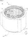
- the structure of a stator 100 according to the first embodiment will be described with reference to FIGS. 1 to 21 .
- the stator 100 has an annular shape centered around a central axis C1.
- the stator 100 is an example of an "armature" in the claims.
- an "axial direction (central axis direction, axis direction)” means a direction (Z direction) along the central axis C1 of the stator 100 (a rotational axis of a rotor 101) as shown in FIG. 1 .
- a “circumferential direction” means a circumferential direction (A1 direction, A2 direction) of the stator 100.
- a “radial direction” means a radial direction (R direction) of the stator 100.
- An “inner radial side” means a direction (R1 direction) toward the central axis C1 of the stator 100 along the radial direction.
- an “outer radial side” means a direction (R2 direction) toward the outside of the stator 100 along the radial direction.
- the stator 100 configures a part of a rotary electric machine 102 together with the rotor 101.
- the rotary electric machine 102 is configured as a motor, a generator, or a motor/generator, for example.
- the stator 100 is disposed on the outer radial side the rotor 101 in which a permanent magnet (not shown) is provided. That is, in the first embodiment, the stator 100 configures a part of the inner rotor type rotary electric machine 102.
- the stator 100 includes a stator core 10, a first insulating member 20, and a coil portion 30. Further, as shown in FIG. 3 , the coil portion 30 includes a first coil assembly 30a (non-lead side coil) and a second coil assembly 30b (lead side coil). Further, as shown in FIG. 3 , the coil portion 30 is composed of a plurality of segment conductors 40.
- the stator 100 includes a second insulating member 21 that is provided separately from the first insulating member 20.
- the stator core 10 is an example of an "armature core” in the claims.
- the first insulating member 20 is an example of a “core leg portion fixing member” in the claims.
- the second insulating member 21 is an example of a "first joint portion insulating member" in the claims.
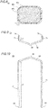
- the stator core 10 has a cylindrical shape with the central axis C1 (see FIG. 1 ) as the central axis. Further, the stator core 10 is formed, for example, by stacking a plurality of electromagnetic steel plates (for example, silicon steel plates) in the axial direction. Here, in the first embodiment, the stator core 10 is formed by stacking a plurality of silicon steel plates having a thermal expansion coefficient K1. As shown in FIG. 4 , the stator core 10 is provided with a back yoke 11 having an annular shape when viewed in the axial direction, and a plurality of slots 12 that is provided on the inner radial side of the back yoke 11 and that extends in the axial direction. The stator core 10 is provided with a plurality of teeth 13 on both sides of each slot 12 in the circumferential direction.
- Each slot 12 is a portion surrounded by a wall portion 11a of the back yoke 11 provided on the outer radial side and a circumferential side surface 13a of the two teeth 13.
- the slot 12 is provided with an opening portion 12a that opens to the inner radial side.
- the slot 12 opens on both sides in the axial direction.
- the teeth 13 are formed so as to protrude radially inward from the back yoke 11, and a protruding portion 13b configuring an opening portion 12a of the slot 12 is formed on a distal end portion on the inner radial side.
- the wall portion 11a and the circumferential side surface 13a are examples of an "end surface of the armature core" in the claims.
- the opening portion 12a has an opening width W1 in the circumferential direction.
- the opening width W1 corresponds to the distance between the distal end portions of the protruding portions 13b of the teeth 13.
- a width W2 of a part of the slot 12 in which the coil portion 30 is disposed is larger than the opening width W1. That is, the slot 12 is configured as a semi-open type slot.
- the width W2 corresponds to the distance between the circumferential side surfaces 13a of the teeth 13 disposed on both sides of the slot 12 in the circumferential direction.
- the width W2 of the slot 12 is substantially constant in the radial direction.
- the coil portion 30 is configured of a flat conductor wire.
- the coil portion 30 is configured of a material having a thermal expansion coefficient K2 larger than the thermal expansion coefficient K1 (linear expansion coefficient) of the stator core 10.
- the coil portion 30 (conductor body 40c) is made of copper or aluminum having the thermal expansion coefficient K2 larger than the thermal expansion coefficient K1.
- the coil portion 30 is formed by the first coil assembly 30a provided on one axial side (arrow Z2 direction side) and the second coil assembly 30b provided on the other axial side (arrow Z1 direction side) being combined in the axial direction and joined.
- the first coil assembly 30a and the second coil assembly 30b are each formed in an annular shape centered around the same central axis C1 (see FIG. 1 ) as the stator core 10.
- the coil portion 30 is formed by joining in a joint portion 90, a first leg portion 71 and a second leg portion 81, described below, of the segment conductors 40.
- the first leg portion 71 is an example of a "short leg portion" in the claims.
- the second leg portion 81 is an example of a "long leg portion” in the claims.
- the coil portion 30 is configured as a wave winding coil, for example. Moreover, the coil portion 30 is configured as a coil of eight turns. That is, the coil portion 30 is configured so that eight segment conductors 40 are disposed in parallel in the slot 12 in the radial direction.
- the coil portion 30 is configured to generate magnetic flux by being supplied with three-phase alternating current power from a power supply unit (not shown).
- the coil portions 30 are connected (wired) by three-phase Y-connection. That is, the coil portion 30 includes a U-phase coil portion 30U, a V-phase coil portion 30V, and a W-phase coil portion 30W.
- the coil portion 30 is provided with a plurality of (for example, two) neutral points N.
- the coil portion 30 is connected in four parallel lines (star connection). That is, the U-phase coil portion 30U is provided with four neutral point connection end portions NtU and four power line connection end portions PtU.
- the V-phase coil portion 30V is provided with four neutral point connection end portions NtV and four power line connection end portions PtV
- the W-phase coil portion 30W is provided with four neutral point connection end portions NtW and four power line connection end portions PtW.
- the neutral point connecting end portion and the power line connecting end portion are simply indicated as a "neutral point connecting end portion Nt" and a "power line connection end portion Pt".
- the first coil assembly 30a is composed of a plurality of first conductors 70 serving as the segment conductors 40. It is preferable that the first coil assembly 30a be configured by combining only the first conductors 70.
- the second coil assembly 30b includes a plurality of (for example, three) power segment conductors 50 (hereinafter, referred to as "power conductors 50") as the segment conductors 40, and a plurality of (for example, two) neutral-point segment conductors 60 (hereinafter referred to as "neutral-point conductors 60") as the segment conductors 40, and second conductors 80 that are conductors (general segment conductors 40) different from the power conductors 50 and the neutral-point conductors 60 among the segment conductors 40 and that configure the coil portion 30. That is, all of the power conductors 50 and the neutral point conductors 60 provided in the stator 100 are provided in the second coil assembly 30b.
- the power conductors 50 and the neutral point conductors 60 are examples of a "second segment conductor” in the claims.
- the first conductors 70 are an example of a "first segment conductor” in the claims.
- the second conductors 80 are an example of the "second segment conductor” in the claims.
- the segment conductor 40 is configured as a flat conductor wire having a substantially rectangular cross section.
- a conductor surface 40b of the segment conductor 40 is provided with an insulating coating 40a that has a thickness t1 and that is different from an insulating layer 20a described later.
- the insulating layer 20a is provided between the leg portions (71, 81) covered by the insulating coating 40a and the stator core 10 (the wall portion 11a and the circumferential side surface 13a).
- the thickness t1 of the insulating coating 40a is set, for example, to such an extent that interphase insulating performance (insulation between the first coil end portions 72 and insulation between the second coil end portions 82 (see FIG. 2 )) can be ensured. Note that, in FIG. 8 , the size relationship such as the thickness is highlighted for the sake of explanation, and the present invention is not limited to this example indicated in the drawing.
- the segment conductors 40 include the first conductors 70 disposed on one axial side (Z2 direction side) of the stator core 10 and the second conductors 80 that are disposed on the other axial side (Z1 direction side) of the stator core 10 and that face the first conductors 70 in the central axis direction. That is, the coil portion 30 is formed by joining the first conductors 70 and the second conductors 80, which are divided into two in the axial direction.
- the second conductors 80 are the segment conductors 40 other than the power conductors 50 and the neutral point conductors 60 among the segment conductors 40 that configure the second coil assembly 30b.
- the power conductor 50, the neutral point conductor 60, and the first conductor 70 include the first leg portion 71 having a first length L1 in the axial direction.
- Each second conductor 80 include the second leg portion 81 that is disposed on the Z1 direction side of the first leg portion 71 and that has a second length L2 that is greater than the first length L1 in the axial direction.
- the first conductors 70 are formed so as to have a U-shape (substantially U-shape) when viewed in the radial direction by connecting a pair of the first leg portions 71 in which the first leg portions 71 are disposed in the slots 12 different from each other.
- the coil pitch of the first conductors 70 is six. That is, the first leg portions 71 of the pair of first leg portions 71 are disposed at positions different in the circumferential direction by six slots 12. That is, five slots 12 are provided between the slot 12 in which one first leg portion 71 of the pair of first leg portions 71 is disposed and the slot 12 in which the other first leg portion 71 of the pair of first leg portions 71 is disposed.
- each first conductor 70 includes the pair of the first leg portions 71 that are disposed in different slots 12 and that are each linearly formed along the axial direction, and a first coil end portion 72.
- the first leg portion 71 means a portion disposed in the slot 12 from the axial position of the end surface 10a (see FIG. 2 ) of the stator core 10.
- the first coil end portion 72 means a portion that is formed to be continuous with the first leg portion 71 and that is disposed on the outer axial side of the end surface 10a of the stator core 10.
- the first coil end portion 72 has a bent shape that bends in the axial direction.
- the first coil end portion 72 has a first crank part 73 formed in a crank shape in which the first crank part 73 is bent in a stepwise manner by the width of one segment conductor 40 in the radial direction when viewed in the axial direction. That is, the radial width of the first crank part 73 is twice the width of one segment conductor 40.
- the axial lengths L1 of the pair of first leg portions 71 are substantially equal to each other.
- the axial length L1 of the first leg portions 71 means the length from the most distal end of the first leg portion 71 to the bent part connected to the first coil end portion 72.
- the axial length L1 is smaller than an axial length L3 of the stator core 10 (see FIG. 2 ).
- the axial length L3 of the stator core 10 means the distance (interval) between the end surface 10a and the end surface 10b in the axial direction.
- the second conductor 80 includes the pair of second leg portions 81 disposed in the slot 12 and the second coil end portion 82.
- the second coil end portion 82 also has a second crank part 83.
- the second conductor 80 is formed to have a U-shape by connecting the pair of second leg portions 81, which is disposed in the different slots 12, to each other.
- the axial lengths L2 of the pair of second leg portions 81 of the second conductor 80 are substantially equal to each other.
- the axial length L2 of the pair of second leg portions 81 of the second conductor 80 is larger than the axial length L1 of the pair of first leg portions 71 of the first conductor 70 (L2>L1).
- the axial length L2 of the second leg portions 81 means the length from the most distal end of the second leg portions 81 to the bent part connected to the second coil end portion 82.
- the power conductor 50 a plurality (for example, four) of the power line connection end portions Pt of the same phase are electrically connected to each other, and a plurality of the connected power line connection end portions Pt and one power terminal member 51 are electrically connected.
- the second leg portion 81 joined to one of the pair of first leg portions 71 (see FIG. 14 ) and the power terminal member 51 are joined.
- the power conductor 50 has a function of introducing electric power into the coil portion 30 from the power supply unit (not shown).
- the power conductor 50 includes an outer radial side power conductor 52 that is disposed on the outer radial side of the slot 12 (see FIG. 1 ) and that has the power line connection end portion Pt, and an inner radial side power conductor 53 that is disposed on the inner radial side and the outer axial side of the outer radial side power conductor 52 and that has the power line connection end portion Pt.
- the power conductor 50 is formed in a bifurcated shape.
- the outer radial side power conductor 52 and the power terminal member 51 are electrically connected by a lead wire 54.
- the inner radial side power conductor 53 and the power terminal member 51 are electrically connected to each other by the lead wire 54.
- the outer radial side power conductor 52 and the inner radial side power conductor 53 are electrically connected via the power terminal member 51 and the lead wire 54.
- the lead wire 54 is formed of a stranded wire (conductor) and an insulating tube 51a is disposed on the outer circumference, for example.
- the outer radial side power conductor 52 and the inner radial side power conductor 53 are each provided with the second leg portion 81 but are not provided with the first coil end portion 72 or the second coil end portion 82. Further, in the outer radial side power conductor 52 and the inner radial side power conductor 53, the lead wire 54 and the second leg portion 81 are joined via a conductor plate 55. For example, the joining is performed by brazing or welding (for example, any one of resistance welding, arc welding, laser welding, or high energy beam welding).
- the neutral point conductor 60 includes an outer radial side neutral point conductor 61 and an inner radial side neutral point conductor 62.
- the outer radial side neutral point conductor 61 and the inner radial side neutral point conductor 62 each include the neutral point N, and the neutral point connecting end portion NtU of the U-phase coil portion 30U, the neutral point connection end portion NtV of the V-phase coil portion 30V, and the neutral point connection end portion NtW of the W-phase coil portion 30W are electrically connected.
- each outer radial side neutral point conductor 61 includes two U-phase W-phase neutral point segment conductors 61a and two V-phase neutral point segment conductors 61b.
- the U-phase W-phase neutral point segment conductors 61a include the U-phase second leg portions 81 connected to the first leg portions 71 of the first conductors 70 for the U-phase among the three-phase alternating current, the W-phase second leg portions 81 connected to the W-phase first leg portions 71, and two neutral point coil end portions 61c that each connect the U-phase second leg portion 81 and the W-phase second leg portion 81.
- the neutral point coil end portion 61c is formed to be continuous with the U-phase second leg portion 81 and is formed to be continuous with the W-phase second leg portion 81.
- the U-phase W-phase neutral point segment conductor 61a is formed to have a substantially U-shape (substantially U-shape) when viewed from the inner radial side.
- the V-phase neutral point segment conductor 61b is formed in a substantially linear shape when viewed from the inner radial side.
- the neutral point coil end portion 61c is formed along the circumferential direction on the outer radial side of the second coil end portion 82 of the second conductor 80.
- the neutral point coil end portion 61c is formed in a substantially arc shape when viewed in the arrow Z2 direction.
- One of the two U-phase W-phase neutral point segment conductors 61a is disposed on the other outer axial side (arrow Z1 direction side).
- the V-phase neutral point segment conductor 61b includes a V-phase second leg portion 81 connected to the V-phase first conductor 70 and a neutral point coil end portion 61d.
- the neutral point coil end portion 61d is formed so as to protrude from the second leg portion 81 in the outer axial direction (in the arrow Z1 direction).
- the two neutral point coil end portions 61d are electrically joined to each other by being joined to both of the two neutral point coil end portions 61c.
- the inner radial side neutral point conductor 62 includes two U-phase W-phase neutral point segment conductors 62a and two V-phase neutral point segment conductors 62b.
- the U-phase W-phase neutral point segment conductors 62a include the U-phase second leg portions 81 connected to the first leg portions 71 of the first conductors 70 for the U-phase among the three-phase alternating current, the W-phase second leg portions 81 connected to the W-phase first conductor 70, and the neutral point coil end portions 62c that each connect the U-phase second leg portion 81 and the W-phase second leg portion 81.
- the neutral point coil end portions 62c are formed to be continuous with the U-phase second leg portions 81 and to be continuous with the W-phase second leg portion 81.
- the U-phase W-phase neutral point segment conductors 62a are formed in a substantially U-shape (substantially U-shape) when viewed from the inner radial side.
- the V-phase neutral point segment conductors 62b are formed in a substantially linear shape when viewed from the inner radial side.
- the neutral point coil end portion 62c is formed so as to protrude axially outward with respect to the second coil end portion 82 of the second conductor 80.
- the neutral-point coil end portion 62c is disposed close to the outer axial side of the second coil end portion 82 of the second conductor 80, and is formed along the circumferential direction when viewed in the axial direction.
- One of the two U-phase W-phase neutral point segment conductors 62a is disposed on outer radial side of the other U-phase W-phase neutral point segment conductor 62a.
- the V-phase neutral point segment conductor 62b includes the V-phase second leg portion 81 connected to the first leg portion 71 of the V-phase first conductor 70, and a neutral point coil end portion 62d.
- the neutral point coil end portion 62d is formed so as to protrude from the second leg portion 81 in the outer axial direction (in the direction of the arrow Z1).
- the two neutral point coil end portions 62d are electrically joined by being joined to both of the two neutral point coil end portions 62c.
- the joining portion 90 in which the first conductor 70 and the second conductor 80 are joined is disposed in the slot 12, on one end portion side (near the end surface 10a) of the axial center of the stator core 10. Further, in all the slots 12 of the stator core 10, the joint portion 90 is provided in the vicinity of the end surface 10a on one axial side.
- the vicinity of the end surface 10a includes, in the axial direction, the position that is on the Z2 direction side of the axial center C2 and that is the same position as the end surface 10a, and the range within the substantially insulating creepage distance in the Z1 direction or the Z2 direction from the end surface 10a, for example.
- the plurality of first leg portions 71 are provided in one slot 12 so as to be adjacent to each other in the radial direction of the stator core 10. That is, the joint portions 90 of the first leg portions 71 and the second leg portions 81 are disposed adjacent to each other in the radial direction in one slot 12.
- the first conductor 70 of the plurality of segment conductors 40 is provided with a first facing surface 74, which is inclined with respect to a plane orthogonal to the axial direction, at the distal end portion of the first leg portion 71.
- the second conductor 80 is provided with a second facing surface 84, which is inclined with respect to the plane orthogonal to the axial direction, at the distal end portion of the second leg portion 81.
- the joining portion 90 is formed by joining the first facing surface 74 and the second facing surface 84, which face each other in the radial direction, of the first conductor 70 and the second conductor 80 which face each other in the axial direction. That is, the joint portion 90 means a portion in which the first conductor 70 and the second conductor 80 are joined.
- the first facing surface 74 and the second facing surface 84 are examples of an "inclined surface" in the claims.
- the first leg portion 71 includes the first facing surface 74 that faces the second leg portion 81 and that also faces the inner radial side (arrow R1 direction side).
- the second leg portion 81 includes the second facing surface 84 that faces the first facing surface 74 and that also faces the outer radial side (arrow R2 direction side).
- the first conductor 70 and the second conductor 80 are joined by joining the first facing surface 74 of the first leg portion 71 and the second facing surface 84 of the second leg portion 81.
- first facing surface 74 of the first leg portion 71 and the second facing surface 84 of the second leg portion 81 are joined by a joining material (not shown), for example.
- the joining material joins and electrically connects the first facing surface 74 and the second facing surface 84.
- the bonding material includes a conductive material such as silver or copper. It is preferable that the joining material is a paste form joining material (silver nanopaste) that contains, as conductive particles, metal particles obtained by miniaturizing silver to a nanometer level, in a solvent.
- the bonding material contains a member (resin member) that volatilizes when heated, and has a function of bringing the first facing surface 74 and the second facing surface 84 close to each other by heating the volatilizing member and decreasing the volume of the bonding material.
- the joint portions 90 are configured so that the joint portions 90 adjacent in the radial overlap with each other when viewed in the radial direction.
- the plurality of (all) joint portions 90 disposed in one slot 12 are configured to overlap with each other when viewed in the radial direction. That is, all the joint portions 90 disposed in one slot 12 are disposed in a state in which the joint portions 90 are aligned along the horizontal direction. In other words, each position of the joint portions 90 in the axial direction in one slot 12 are substantially equal to each other.
- the joining portion 90 is a part in which the first facing surface 74 of the first leg portion 71 and the second facing surface 84 of the second leg portion 81 are joined (overlapped) when viewed in the radial direction.
- the first insulating member 20 is disposed between the wall portion 11a and the teeth 13 and the first leg portion 71 and the second leg portion 81 (segment conductor 40).
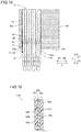
- the first insulating member 20 has a three-layer configuration. Specifically, as shown in FIG. 14 , in the first embodiment, the first insulating member 20 includes, in the slot 12: an insulating layer 20a that is provided between the wall portion 11a of the back yoke 11 and the circumferential side surface 13a of the teeth 13 (see FIG.
- the fixing layer 20c is preferably configured as an adhesive layer containing an adhesive.
- the position P2 includes, in the axial direction, the entire region inside the slot 12 of the part excluding the axial position PI, and a part near the end surface 10b of the stator core 10 (including the part outside the slot 12 in the axial direction) for example.
- the insulating layer 20a and the fixing layer 20c are examples of a "first insulating layer” and a “first fixing layer” in the claims, respectively.
- the first insulating member 20 is disposed so as to integrally cover the surroundings of the second leg portions 81 disposed in parallel in the radial direction when viewed in the arrow Z2 direction. In other words, both sides in the circumferential direction and both sides in the radial direction of the second leg portions 81 disposed in parallel in the radial direction are covered by the first insulating member 20. In this way, the first insulating member 20 can ensure the insulation between the joint portion 90 and the stator core 10.
- the insulating layer 20a is configured of a poly phenylene sulfide resin (PPS), for example.
- PPS poly phenylene sulfide resin
- the insulating layer 20a may be formed in a non-woven fabric form such as aramid paper.
- the insulating layer 20a is provided from the end surface 10a on one axial side of the stator core 10 across to the end surface 10b on the other axial side. That is, the insulating layer 20a is disposed so as to cover the wall portion 11a and the circumferential side surface 13a in each slot.
- cover does not only mean to cover all parts of the wall portion 11a and the circumferential side surface 13a, but means a broad concept including a case in which the inner radial side part (distal end gap part) of the circumferential side surface 13a is exposed, as shown in FIG. 5 .
- the fixing layer 20c includes a foaming agent 20d (expanding agent) that foams due to heat.
- the fixing layer 20c is formed, for example, by mixing a plurality of capsule bodies as the foaming agent 20d with a thermosetting resin 20e.
- the foaming agent 20d is configured to expand the volume of the capsule body when heated to a foaming temperature T1 or higher.
- the thickness of the fixing layer 20c increases from t2 (see FIG. 17 ) to t3 (see FIG. 18 ) by being heated in the manufacturing process of the stator 100, for example.
- the fixing layer 20c fills the space between the second leg portion 81 and the wall portion 11a and the circumferential side surface 13a by the foaming agent 20d foaming (expanding) when heated.
- the foaming agent 20d is an example of a "first foaming agent" in the claims.
- thermosetting resin 20e is configured to be cured by being heated to a curing temperature T2 or higher which is higher than the foaming temperature T1.
- the thermosetting resin 20e forming the fixing layer 20c is, for example, an epoxy resin.
- the fixing layer 20c is configured so that when the fixing layer 20c is heated, the thermosetting resin 20e is cured so that the second leg portion 81 and the wall portion 11a and the circumferential side surface 13a are bonded and fixed.
- the fixing layer 20c containing the foaming agent 20d in the foamed state is filled between at least a part of the second leg portion 81, and the wall portion 11a and the circumferential side surface 13a that configure the slot 12, at the position P2 different from the position P1 in the axial direction corresponding to the joint portion 90.
- the fixing layer 20c is provided so as to overlap with the part 20b of the insulating layer 20a on the other axial side (Z1 direction side) of the position P1 in the axial direction corresponding to the joint portion 90.
- the fixing layer 20c is provided so as to overlap with the part 20b of the insulating layer 20a on the other axial side of the vicinity of the end surface 10a on the one axial side (Z2 direction side). Further, the fixing layer 20c is provided in the slot 12 so as to overlap with the part 20b of the insulating layer 20a that is disposed between the second leg portion 81 and the stator core 10. For example, as shown in FIG. 16 , the fixing layer 20c is provided so as to overlap with and sandwich the insulating layer 20a in the part 20b of the insulating layer 20a at a position different from the axial position corresponding to the joint portion 90.
- the first insulating member 20 provided between the slot 12 and the coil portion 30 and the second insulating member 21 provided separately from the first insulating member 20 are provided.
- the joint portions 90 in which the first conductor 70 and the second conductor 80 are joined between the coils adjacent in the radial direction in one slot 12 are insulated by the second insulating member 21 that is provided separate from the first insulating member 20.
- the term "coils adjacent in the radial direction" means a linear part of the coil portion 30 that is disposed in the slot 12 after the first conductor 70 and the second conductor 80 are joined.
- the second insulating member 21 is formed by folding one sheet-shaped insulating member such as a Nomex.
- the second insulating member 21 includes: a facing surface insulating part 21a that covers facing surfaces 90a of the joint portions 90 that are adjacent in the radial direction; and a circumferential surface insulating part 21b that is continuous from end portions of the facing surface insulating part 21a in the circumferential direction and that covers one of the circumferential surfaces 90b of the joint portion 90 that are adjacent in the radial direction for at least the insulation distance.
- the facing surface 90a of the joint portion 90 means an outer radial surface and an inner radial surface, which face each other, of the joint portions 90 that are radially adjacent to each other.
- the insulation distance means a distance (creepage distance) that is a length along the circumferential surface insulating part 21b in the radial direction and that is sufficient for insulating the joint portions 90, which are adjacent to each other, from each other.
- the second insulating member 21 includes a part 21c that covers an outer radial side of the joint portion 90 disposed on the outermost radial side, and a part 21d that covers the inner dial side of the joint portion 90 disposed on the innermost radial side.
- the facing surface insulating parts 21a that are adjacent in the radial direction are connected to each other by the circumferential surface insulating part 21b in one or the other circumferential direction.
- the facing surface insulating part 21a on the outer radial side among the pair of facing surface insulating parts 21a disposed adjacent to each other in the radial direction, the circumferential surface insulating part 21b provided on one side in the circumferential direction, the facing surface insulating part 21a on the inner radial side among the pair of facing surface insulating parts 21a, and the circumferential surface insulating part 21b provided on the other side in the circumferential direction are formed to be continuous.
- the circumferential surface 90b on the A1 direction side of the joint portion 90 and the circumferential surface 90b on the A2 direction side of the joint portion 90 are alternately covered by the circumferential surface insulating part 21b.
- the second insulating member 21 is configured so as not to continuously cover the circumferential surfaces 90b of the plurality of joint portions 90 disposed adjacent to each other in the radial direction.
- the second insulating member 21 has a meandering shape (bellows shape) when viewed from the central axis direction. Further, all the joint portions 90 disposed in one slot 12 are insulated from each other by one second insulating member 21. This makes it possible to reduce the number of steps for disposing the second insulating member 21 as compared to the case in which the plurality of joint portions 90 disposed in one slot 12 are individually covered by the insulating member.
- the second insulating member 21 is configured to be expandable/contractible along the radial direction.
- the second insulating member 21 is made of a flexible sheet-shaped insulating member, and is configured to not continuously cover the circumferential surfaces 90b of the plurality of joint portions 90 disposed adjacent to each other in the radial direction.
- the second insulating member 21 can be deformed with the movement of the first leg portion 71 and the second leg portion 81.
- the second insulating member 21 is disposed so that an edge portion on one axial side protrudes outward from the end surface 10a of the stator core 10 in the central axis direction. Specifically, in the central axis direction, the Z2 direction side of the second insulating member 21 protrudes outward from the end surface 10a of the stator core 10, and the Z1 direction side is disposed in the slot 12.
- the first insulating member 20 is also disposed together with the second insulating member 21 so as to protrude outward from the end surface 10a of the stator core 10 in the central axis direction.
- a height position h1 of the part of the second insulating member 21 protruding outward from the end surface 10a of the stator core 10 and a height position h2 of the part of the first insulating member 20 protruding outward from the end surface 10a of the stator core 10 are substantially equal.
- the protruding amount of the first insulating member 20 and the second insulating member 21 from the end surface 10a of the stator core 10 is adjusted to a degree in which the first insulating member 20 and the second insulating member 21 are not bent by coming into contact with the second coil end portion 82 of the second segment conductor 80.
- a length L12 of the second insulating member 21 is smaller than a length L11 of the first insulating member 20 in the central axis direction.
- the length L11 of the first insulating member 20 is larger than the length L3 of the stator core 10 in the central axis direction.
- the length L12 of the second insulating member 21 is smaller than the length L3 of the stator core 10.
- the second insulating member 21 is provided so as to cover the joint portion 90 and extend from the joint portion 90 toward the Z1 direction side and the Z2 direction side.
- the length L12 of the second insulating member 21 is adjusted based on the magnitude of the voltage applied to the coil portion 30 (based on the required creepage distance).
- the first insulating member 20 has a part 20f that overlaps with the second insulating member 21 and the part 20b that does not overlap with the second insulating member 21 when viewed in the radial direction. Specifically, the first insulating member 20 overlaps with the second insulating member 21 in the vicinity of the end portion (end surface 10a) in the central axis direction in the slot 12.
- a thickness t11 of the part 20f of the first insulating member 20 that overlaps with the second insulating member 21 is smaller than a thickness t12 of the part 20b of the first insulating member 20 that does not overlap with the second insulating member 21.
- a thickness t13 of the second insulating member 21 is smaller than the thickness t11. Further, the thickness t12 is obtained by adding the thickness t11 to the thickness t3 of two sheets (t3 ⁇ 2) of the fixing layer 20c.
- the fixing layer 20c is not provided and a clearance C11 is provided, between the joint portion 90 (see FIG. 14 ) and the stator core 10 (the wall portion 11a and the circumferential side surface 13a). Further, the fixing layer 20c is provided between a part of the second leg portion 81 (see FIG. 14 ) other than the joint portion 90 (that is, a part of the second leg portion 81 on the end surface 10b side with respect to the joint portion 90) and the stator core 10 (the wall portion 11a and the circumferential side surface 13a).
- the clearance C11 is a clearance formed by the difference between the thickness t12 of the part 20b and the thickness t11 of the part 20f.
- the second insulating member 21 is disposed on one axial side (Z2 direction side) with respect to the fixing layer 20c of the first insulating member 20 and between the joint portions 90 in the radial direction, and is configured to insulate the joint portions 90 from each other.
- the fixing layer 20c is provided so as to overlap with the part 20b of the insulating layer 20a that does not overlap with the second insulating member 21 in the radial direction.
- the insulating layer 20a is disposed in the part 20f that overlaps with the second insulating member 21 when viewed in the radial direction.
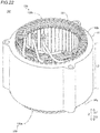
- stator 200 according to a second embodiment will be described.
- insulating members (121, 122) that are integrally formed are provided, unlike the stator 100 of the first embodiment that has the first insulating member 20 and the second insulating member 21 that are provided separately from each other.
- the same configurations as those in the first embodiment are indicated by the same reference numerals as those in the first embodiment and are shown in the drawings, and the description thereof will be omitted.
- stator 200 The structure of the stator 200 according to the second embodiment will be described with reference to FIG. 4 and FIGS. 22 to 31 .
- the stator 200 is an example of the "armature" in the claims.
- the stator 200 includes the sheet-shaped insulating member 121 and a coil portion 130.
- the coil portion 130 also includes a first coil assembly 130a (non-lead side coil) and a second coil assembly 130b (lead side coil). Further, the coil portion 130 is composed of a plurality of segment conductors 140 (see FIGS. 24A and 24B ).
- the insulating member 121 is an example of a "second joint portion insulating member" in the claims.
- the insulating member 121 (contact portion insulating part 121c described below) and the core leg portion insulating part 122 described below each have the same length L22.
- the length L22 is larger than the length L3 of the stator core 10 in the central axis direction.
- illustration of the first conductor 170 and the second conductor 180 is omitted for simplification.
- each shape of the insulating member 121 and the core leg portion insulating part 122 are schematically illustrated.
- the segment conductor 140 is configured as a flat conductor wire having a substantially rectangular cross section.
- a first leg portion 171 (second leg portion 181), which will be described below, is not covered with the insulating coating and a conductor surface 140b is exposed (see FIG. 24A ).
- an insulating coating 140a (see FIG. 24B ) having a thickness t21 is provided on the conductor surface 140b of a first coil end portion 172 (second coil end portion 182) described below.
- the thickness t21 of the insulating coating 140a is set to ensure an interphase insulating performance (insulation between the first coil end portions 172 and insulation between the second coil end portions 182 (see FIGS. 25A and B, and FIGS. 26A and B )).
- FIGS. 24A and 24B for the sake of explanation, the magnitude relationship such as the thickness is emphasized.
- the present invention is not limited to this illustrated example.
- FIGS. 24A and 24B only the first conductor 170 described below is shown.
- the second conductor 180 is similar, illustration thereof is omitted.
- the conductor surface 140b is an example of a "metal surface" in the claims.
- the plurality of segment conductors 140 includes a plurality of first conductors 170 disposed on one axial side (Z2 direction side) of the stator core 10 and a plurality of second conductors 180 disposed on the other axial side (Z1 direction side) of the stator core 10.
- the first conductor 170 and the second conductor 180 are disposed facing each other in the central axis direction.
- the first conductor 170 also includes the first leg portion 171 having a length L31 in the axial direction.
- the first leg portion 171 extends to the other side (Z1 direction side) in the central axis direction.
- the second conductor 180 also includes the second leg portion 181 having a length L32 in the axial direction.
- the second leg portion 181 extends to one side (Z2 direction side) in the central axis direction.
- the length L31 of the first leg portion 171 and the length L32 of the second leg portion 181 are substantially the same. Further, each of the first leg portion 171 and the second leg portion 181 is inserted in the slot 12.
- the first conductor 170 and the second conductor 180 are examples of a "third segment conductor" and a "fourth segment conductor” in the claims, respectively.
- the plurality of first conductors 170 is formed to have a U-shape (substantially U-shape) when viewed in the radial direction by connecting a pair of the first leg portions 171, which are disposed in different slots 12, to each other.
- the coil pitch of the first conductor 170 is six. That is, the first leg portions 171 are disposed at positions different in the circumferential direction by six slots 12. That is, five slots 12 are provided between the slot 12 in which one first leg portion 171 of the pair of first leg portions 171 is disposed and the slot 12 in which the other first leg portion 171 is disposed.
- the first conductor 170 includes the pair of first leg portions 171, which are each disposed in different slots 12 and which are linearly formed along the axial direction, and the first coil end portion 172.
- the first leg portion 171 means a part disposed in the slot 12 from the axial position of the end surface 10a (see FIG. 2 ) in the central axis direction of the stator core 10, and the first coil end portion 172 means a part that is formed to be continuous with the first leg portion 171 and that is disposed on the outer axial side of the end surface 10a of the stator core 10.
- the first coil end portion 172 has a bent shape that bends in the axial direction.
- first coil end portion 172 has a first crank part 173 formed in a crank shape that is bent in a stepwise shape for a width of one segment conductor 140 in the radial direction when viewed in the axial direction. That is, the radial width of the first crank part 173 is twice the width of one segment conductor 140.
- the axial lengths L31 of the pair of first leg portions 171 are substantially equal to each other.
- An axial length L31 means the length of the part of the first conductor 170 that extends linearly in the central axis direction within the slot 12.
- the axial length L31 is smaller than the central axis direction length L3 (see FIG. 23 ) of the stator core 10 (slot 12).
- the second conductor 180 includes a pair of the second leg portions 181 disposed in the slot 12 and the second coil end portion 182. Also, the second coil end portion 182 has a second crank part 183.
- the second conductor 180 is formed to have a U-shape by connecting the pair of second leg portions 181, which are disposed in different slots 12, to each other.
- the axial lengths L32 of the pair of second leg portions 181 of the second conductor 180 are substantially equal to each other.
- the axial length L32 means the length of the part of the second conductor 180 that extends linearly in the central axis direction within the slot 12.
- the plurality of first leg portions 171 are provided in each of the plurality of slots 12 so that the first leg portions 171 are adjacent to each other in the radial direction of the stator core 10.
- the plurality of second leg portions 181 are provided in each of the plurality of slots 12 so that the second leg portions 181 are adjacent to each other in the radial direction of the stator core 10.
- first surfaces 171a provided on the first leg portions 171 and the second surfaces 181a provided on the second leg portions 181 are disposed alternately along the radial direction.
- Each first surface 171a is provided on a distal end portion 171b side of the first leg portion 171.
- Each second surface 181a is provided on a distal end portion 181b side of the second leg portion 181.
- the first surface 171a and the second surface 181a are provided so as to be in contact with each other as described below, and the first surface 171a and the second surface 181a that are in contact with each other are disposed so as to face each other in the radial direction.
- the stator 200 includes a spring member 210 that is provided in each of the plurality of slots 12 so as to be sandwiched between the coil portion 130 and the opening portion 12a (protruding portion 13b) of the slot 12. That is, the spring member 210 is provided in a distal end clearance 12b provided inside the slot 12 in the radial direction.
- the spring member 210 is configured to press the coil portion 130 from the inner radial side of the coil portion 130 in the radial direction so that the first surface 171a of the first leg portion 171 of the first conductor 170 and the second surface 181a of the second leg portion 181 of the second conductor 180 are in contact with each other.
- a contact portion 190 is formed by contact between the first surface 171a of the first leg portion 171 and the second surface 181a of the second leg portion 181.
- the contact portion 190 is an example of a "joint portion" in the claims.
- the first surface 171a and the second surface 181a are in contact with each other by being pressed by the spring member 210 without a bonding agent being interposed between the first surface 171a and the second surface 181a. That is, the first surface 171a and the second surface 181a are not joined, and the contact state between the first surface 171a and the second surface 181a is maintained by the pressing force of the spring member 210.
- a plurality of sets (eight in the second embodiment) of the first surface 171a and the second surface 181a that are in contact with each other are provided in one slot 12. That is, a plurality of the contact portions 190 is provided in one slot 12. The contact portions 190 are disposed adjacent to each other in the radial direction within one slot 12.
- a plurality of sets (eight in the second embodiment) of the first surface 171a and the second surface 181a that are in contact with each other are provided in one slot 12. That is, a plurality of the contact portions 190 is provided in one slot 12. The contact portions 190 are disposed adjacent to each other in the radial direction within one slot 12.
- each of the plurality of contact portions 190 is disposed within the slot 12, in a central portion in the central axis direction of the stator core 10.
- the spring member 210 is also disposed in the central portion of the stator core 10 in the central axis direction. Specifically, the spring member 210 is provided so as to overlap with each of the plurality of contact portions 190 when viewed in the radial direction.
- each of the first surface 171a and the second surface 181a is plated. That is, the plated surfaces (the first surface 171a and the second surface 181a) are in contact with each other.
- metals such as nickel (Ni), silver (Ag), gold (Au), and tin (Sn) are used.
- the plating process may be performed using a plurality of metals (for example, Ni and Ag) among the above metals.
- the first leg portion 171 includes a first surface forming portion 171c in which the first surface 171a is formed.
- the first surface forming portion 171c (first surface 171a) is provided so as to extend along the central axis direction.
- the first leg portion 171 includes a first leg body portion 171d that is provided on one side (Z2 direction side) in the central axis direction of the first surface forming portion 171c so as to be continuous from the first surface forming portion 171c.
- the first surface forming portion 171c has a radial thickness t31.
- the first leg body portion 171d has a radial thickness t32.
- the radial thickness t32 of the first leg body portion 171d is greater than the radial thickness t31 of the first surface forming portion 171c.
- first leg portion 171 includes a first step portion 171e provided between the first surface forming portion 171c and the first leg body portion 171d.
- a clearance portion 171f is provided between the first step portion 171e and the distal end portion 181b of the second leg portion 181.
- the second leg portion 181 includes a second surface forming portion 181c in which the second surface 181a is formed.
- the second surface forming portion 181c (second surface 181a) is provided so as to extend along the central axis direction.
- the second leg portion 181 includes a second leg body portion 181d that is provided on the other side (Z1 direction side) in the central axis direction of the second surface forming portion 181c so as to be continuous from the second surface forming portion 181c.
- the second surface forming portion 181c has a radial thickness t33.
- the second leg body portion 181d has a radial thickness t34.
- the radial thickness t34 of the second leg body portion 181d is greater than the radial thickness t33 of the second surface forming portion 181c.
- the second leg portion 181 includes a second step portion 181e provided between the second surface forming portion 181c and the second leg portion main body portion 181d.
- a clearance portion 181f is provided between the second step portion 181e and the distal end portion 171b of the first leg portion 171.
- the radial thickness t31 of the first surface forming portion 171c and the radial thickness t33 of the second surface forming portion 181c are substantially equal.
- the radial thickness t32 of the first leg body portion 171d and the radial thickness t34 of the second leg body portion 181d are substantially equal. Note that, in FIG. 28 , in order to highlight the insulating member 121, the insulating member 121 is illustrated so as to have a thickness greater than the actual thickness.
- the sheet-shaped insulating member 121 is provided so as to insulate the contact portions 190 between the coils adjacent in the radial direction in one slot 12. That is, the insulating member 121 is provided so as to insulate the contact portions 190 from each other, in which the first leg portion 171 in which the conductor surface 140b (see FIGS. 24A and 24B ) is exposed and the second leg portion 181 in which the conductor surface 140b is exposed are in contact with each other without interposing a bonding agent.
- the insulating member 121 is provided between each of the plurality of (eight in the second embodiment) coils (a set of the first leg portion 171 and the second leg portion 181 that are in contact with each other) disposed in the radial direction in the slot 12.
- the insulating member 121 is formed by folding one sheet-shaped insulating member such as a Nomex.
- the insulating member 121 includes: facing surface insulating parts 121a that cover facing surfaces 190a of the contact portions 190 that are adjacent in the radial direction; and a circumferential surface insulating part 121b that is continuous from both end portions of the facing surface insulating part 121a in the circumferential direction and that covers one of the circumferential surfaces 190b of the contact portions 190 that are adj acent in the radial direction for at least the insulation distance.
- the facing surfaces 190a of the contact portions 190 mean an outer radial surface and an inner radial surface of the contact portions 190, which face each other in the radial direction.
- the insulation distance is a length along the radial direction of the circumferential surface insulating part 121b and means a distance (creepage distance) sufficient for insulating the contact portions 190 adjacent to each other in the radial direction.
- the circumferential surfaces 190b mean surfaces of the contact portions 190 that intersect with the circumferential direction. In other words, the circumferential surfaces 190b mean surfaces extending in the radial direction and the axial direction.
- the insulation distance is an example of a "predetermined distance" in the claims.
- the insulating member 121 includes the contact portion insulating parts 121c that are formed so that the following are continuous: the facing surface insulating part 121a on the outer radial side among a pair of the facing surface insulating parts 121a disposed adjacent to each other in the radial direction; the circumferential surface insulating part 121b provided on one circumferential side; the facing surface insulating part 121a on the inner radial side among the pair of the facing surface insulating parts 121a; and the circumferential surface insulating part 121b provided on the other side in the circumferential direction.
- the stator 200 includes the core leg portion insulating part 122 that is provided between the slot 12 and the coil portion 130 and that is integrally formed with the contact portion insulating part 121c. That is, the core leg portion insulating part 122 has a sheet shape similar to the contact portion insulating part 121c and is made of the same material as the contact portion insulating part 121c. Further, the contact portion insulating part 121c and the core leg portion insulating part 122 have the same thickness (not shown). The contact portion insulating part 121c and the core leg portion insulating part 122 have the same length L22 (see FIG. 27 ) in the central axis direction.
- the core leg portion insulating part 122 is an example of the "core leg portion fixing member" in the claims.
- the core leg portion insulating part 122 has the one side insulating part 122a that is continuous with the facing surface insulating part 121a on the outermost radial side and that is provided, on one side of the slot 12 in the circumferential direction (left side in FIG. 29 ), between the slot 12 (circumferential side surface 13a) and the coil portion 130 (circumferential surface 190b). Further, the core leg portion insulating part 122 has the other side insulating part 122b that is continuous with the facing surface insulating part 121a on the innermost radial side and that is provided, on the other side of the slot 12 in the circumferential direction (right side in FIG. 29 ), between the slot 12 (circumferential side surface 13a) and the coil portion 130 (circumferential surface 190b).
- the one side insulating part 122a (other side insulating part 122b) is provided so that a part sandwiched between the circumferential side surface 13a and the circumferential surface 190b, and a part sandwiched between the circumferential side surface 13a and the circumferential surface insulating part 121b that covers the circumferential surface 190b are arranged alternately along the radial direction.
- the one side insulating part 122a extends from an outer radial side end portion 230a of the coil portion 130 in the slot 12 to an inner radial side end portion 230b (so as to extend over the end portion 230b).
- the other side insulating part 122b extends from the inner radial side end portion 230b of the coil portion 130 in the slot 12 to the outer radial side end portion 230a (so as to extend over the end portion 230a).
- the coil portion 130 in the slot 12 is provided so as to be surrounded by the facing surface insulating part 121a on the outermost radial side, the facing surface insulating part 121a on the innermost radial side, the one side insulating part 122a, and the other side insulating part 122b.
- the core leg portion insulating part 122 includes an inner radial side insulating part 122c that is continuous with the one side insulating part 122a and that is provided so as to cover the facing surface insulating part 121a on the innermost radial side from the inner radial side. Further, the core leg portion insulating part 122 has an outer radial side insulating part 122d that is continuous with the other side insulating part 122b and that is provided so as to cover the facing surface insulating part 121a on the outermost radial side from the outer radial side.
- the inner radial side insulating part 122c is provided so as to be sandwiched between the facing surface insulating part 121a on the innermost radial side and the spring member 210. That is, the coil portion 130 and the spring member 210 are insulated from each other by the facing surface insulating part 121a on the innermost radial side and the inner radial side insulating part 122c.
- the outer radial side insulating part 122d is provided so as to be sandwiched between the facing surface insulating part 121a on the outermost radial side and the wall portion 11a of the slot 12.
- the coil portion 130 and the wall portion 11a (stator core 10) of the slot 12 are insulated from each other by the facing surface insulating part 121a on the outermost radial side and the outer radial side insulating part 122d.
- the inner radial side insulating part 122c has a length L41 in the circumferential direction.
- the outer radial side insulating part 122d has a length L42 in the circumferential direction.
- Each of the length L41 of the inner radial side insulating part 122c and the length L42 of the outer radial side insulating part 122d is greater than half the width W2 of the slot 12 (see FIG. 4 ), for example.
- the length L22 of each of the contact portion insulating part 121c (see FIG. 29 ) and the core leg portion insulating part 122 (see FIG. 29 ) in the central axis direction is greater than a length L62 of the slot 12 in the central axis direction.
- the length L62 of the slot 12 in the central axis direction is equal to the length L3 of the stator core 10 in the central axis direction (see FIG. 22 ).
- each of the contact portion insulating part 121c and the core leg portion insulating part 122 is disposed so that edge portions on both sides in the central axis direction protrude outward from the end surfaces (10a, 10b) of the stator core 10 in the central axis direction.
- each of the contact portion insulating part 121c and the core leg portion insulating part 122 is provided across the entire slot 12, in the central axis direction.
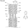
- the contact portion insulating part 121c includes an insulating layer 123a and a fixing layer 123b that includes a foaming agent 123c that foams due to heat.
- the foaming agent 123c foams and expands so as to fix a coil (a pair in which the first leg portion 171 and the second leg portion 181 are in contact with each other) in at least the central axis direction with respect to a coil adjacent in the circumferential direction.
- the fixing layer 123b is provided on both surfaces of the insulating layer 123a. When the fixing layer 123b is heated, a thermosetting resin 123d is cured.
- the fixing layer 123b of the contact portion insulating part 121c bonds the adjacent coils to each other to fix the coils.
- FIG. 30 illustration of the stator core 10 and the like is omitted for simplification.
- the insulating layer 123a and the fixing layer 123b are examples of a "second insulating layer” and a “second fixing layer” in the claims, respectively.
- the foaming agent 123c is an example of a "second foaming layer" in the claims.
- the core leg portion insulating part 122 includes an insulating layer 124a and a fixing layer 124b that includes a foaming agent 124c that foams due to heat.
- the foaming agent 124c foams and expands so as to fix each of the first leg portion 171 and the second leg portion 181 in at least the central axis direction with respect to the stator core 10.
- the fixing layer 124b of the core leg portion insulating part 122 is configured to bond and fix each of the first leg portion 171 and the second leg portion 181 to the stator core 10.
- the insulating member 121 and the core leg portion insulating part 122 are illustrated to have a thickness larger than the actual thickness so as to highlight the insulating member 121 and the core leg portion insulating part 122. Since the insulating layer 123a (124a) and the fixing layer 123b (124b) have the same configurations (materials) as the insulating layer 20a and the fixing layer 20c of the first embodiment, detailed description thereof will be omitted.
- the insulating layer 124a and the fixing layer 124b are examples of the "first insulating layer” and the "first fixing layer” in the claims, respectively.
- the foaming agent 124c is an example of the "first foaming layer" in the claims.
- the fixing layer 124b (fixing layer 123b) is provided so as to be separated into two parts, which are a part on the one side (Z2 direction side) in the central axis direction with respect to the first step portion 171e (see FIG. 36) and a part on the other side (Z1 direction side) in the central axis direction with respect to the second step portion 181e (see FIG. 36).
- the position P4 includes, in the axial direction, the entire region inside the slot 12 of the part excluding the axial position P3 in the axial direction, and the near the end surface 10b of the stator core 10 (including the part outside the slot 12 in the axial direction), for example.
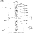
- the fixing layer 124b is not provided and a clearance C21 is provided, between the contact portion 190 and the circumferential side surface 13a (wall portion 11a) of the stator core 10.
- the fixing layer 124b is provided between the leg portions (171, 181) other than the contact portion 190 and the circumferential side surface 13a (wall portion 11a) of the stator core 10.
- FIG. 31 shows only the clearance C21 between the circumferential side surface 13a and the contact portion 190.
- stator 200 Next, with reference to FIG. 32 , a manufacturing process of the stator 200 will be described.
- step S1 the insulating member 121 (contact portion insulating part 121c) and the core leg portion insulating part 122 are integrally inserted (placed) in the slot 12.
- step S2 the second leg portion 181 (see FIG. 27 ) of the second conductor 180 is inserted in the slot 12 from the other side (Z1 direction side) in the central axis direction.
- step S3 the first leg portion 171 (see FIG. 27 ) of the first conductor 170 is inserted in the slot 12 from one side (Z2 direction side) in the central axis direction. At this time, the first leg portion 171 is disposed so that the first surface 171a of the first leg portion 171 and the second surface 181a of the second leg portion 181 face each other.
- step S4 the spring member 210 (see FIG. 27 ) is inserted in the slot 12 from the inner radial side through the opening portion 12a of the slot 12.
- step S5 the stator core 10 is heated and the fixing layer 123b is heated and thus, the foaming agent 123c is foamed and the fixing layer 123b is expanded. In this way, the coil portion 130 is fixed to the slot 12 at least in the central axis direction.
- the configuration is such that the first fixing layer (20c, 124b) of the core leg portion fixing member (20, 122) is provided in the part (20b, 124e) at the position (P2, P4) different from the position (P1) in the central axis direction corresponding to the joint portion (90, 190) so as to fix the armature core (10) and the leg portion (81, 171, 181).
- the first fixing layer (20c, 124b) is not provided on the joint portion (90, 190)
- the relative positions of the joint portion (90, 190) and the armature core (10) is not fixed due to fixing by the first fixing layer (20c, 124b).
- the first fixing layer (20c, 124b) of the core leg portion fixing member (20, 122) is configured to fix the armature core (10) and the leg portion (81, 171, 181), there is no need to form the core leg portion fixing member (20, 122) by molding resin so that the segment conductor (40, 140) can be press-fitted to the core leg portion fixing member (20, 122).
- the manufacturing equipment of the armature (100, 200) is not required.
- joint portion (90, 190) has a broad meaning including not only the part joined via the bonding agent but also the part that is only in contact without the bonding agent.
- the first fixing layer (20c, 124b) contains a first foaming agent (20d, 124c) that foams due to heat, and at a position (P2, P4) different from the position (P1, P3) in the central axis direction corresponding to the joint portion (90, 190), the first fixing layer (20c, 124b) containing the first foaming agent (20d, 124c) in a foamed state is filled between an end surface (11a, 13a) of the armature core (10) and the leg portion (81, 171, 181).
- the segment conductor (40, 140) can be disposed in the slot (12) after the core leg portion fixing member (20, 122) having the first fixing layer (20c, 124b) containing the first foaming agent (20d, 124c) in a non-foamed state is disposed in the slot (12).
- the leg portion (81, 171, 181) can be inserted in the slot (12) while the thickness (t2) of the first fixing layer (20c, 124b) is made relatively small to prevent the leg portion (81, 171, 181) and the core leg portion fixing member (20, 122) from mechanically interfering.
- insertability of the leg portion (81, 171, 181) into the slot (12) can be improved.
- the first foaming agent (20d, 124c) of the first fixing layer (20c, 124b) is foamed after the leg portion (81, 171, 181) is disposed in the slot (12)
- the core leg portion fixing member (20, 122) further includes a first insulating layer (20a, 124a) that is provided in the slot (12), between the end surface (11a, 13a) of the armature core (10) and the leg portion (71, 81, 171, 181), and that insulates the end surface (11a, 13a) of the armature core (10) and the leg portion (71, 81, 171, 181).
- the first fixing layer (20c, 124b) is provided so as to overlap with a part (20b, 124e) of the first insulating layer (20a, 124a) at a position (P2, P4) different from the position (P1, P3) in the central axis direction corresponding to the joint portion (90, 190).
- a position (P2, P4) different from the position (P1, P3) in the central axis direction corresponding to the joint portion (90, 190).
- the joint portion (90) is provided on one side in the central axis direction with respect to a central portion (C2) of the slot (12) in the central axis direction, and the first fixing layer (20c) is provided so as to overlap with a part (20b) of the first insulating layer (20a) on the other side in the central axis direction with respect to a position (P1) in the central axis direction corresponding to the joint portion (90).
- the length (L2) in the central axis direction is larger than that of the part (20f) on the one side.
- the first insulating layer (20a) is provided from one side end portion (10a) across to the other side end portion (10b) of the end surface (11a, 13a) of the armature core (10) in the central axis direction, and the first fixing layer (20c) is provided so as to overlap with a part (20b) of the first insulating layer (20a) on the other side in the central axis direction with respect to the central portion (C2) in the central axis direction.
- the coil portion (30) is formed by joining, in the joint portion (90), among the leg portions (81) of the plurality of segment conductors (40), a short leg portion (71) that is disposed on one side in the central axis direction and that has a first length (L1) in the central axis direction, and a long leg portion (81) that is disposed on the other side in the central axis direction and that has a second length (L2) that is greater than the first length (L1) in the central axis direction, and the first fixing layer (20c) is provided so as to overlap with a part (20d) of the first insulating layer (20a) disposed between the long leg portion (81) and the armature core (10), in the slot (12) or on the outer side of the one slot (12) in the central axis direction.
- the first fixing layer (20c) is provided only between the short leg portion (71) and the armature core (10)
- the first fixing layer (20c) is at least provided between the long leg portion (81), which is relatively long in the central axis direction and the armature core (10)
- the fixing strength of the coil portion (30) and the armature core (10) can be improved.
- the plurality of segment conductors (40) includes a first segment conductor (40) formed in a U-shape by connecting a pair of the short leg portions(71), which are disposed in different slots (12) from each other, to each other, and a second segment conductor (40) that is formed in a U-shape by connecting a pair of the long leg portions (81), which are disposed in different slots (12) from each other, to each other.
- two leg portions (71, 81) can be fixed to the armature core (10) with the first fixing layer (20c).
- the fixing strength between the segment conductor (40) and the armature core (10) can be increased as compared to the case in which the segment conductor (40) and the armature core (10) are fixed at one place.
- a plurality of the leg portions (71, 81) is provided adjacent to each other in a radial direction of the armature core (10), in the slot (12) or on the outer side of the one slot (12) in the central axis direction, the joint portions (90) of the plurality of leg portions (71, 81) are disposed adjacent to each other in the radial direction, and a first joint portion insulating member (21) that is disposed on one side with respect to the first fixing layer (20c) in the central axis direction and between the joint portions (90) in the radial direction, and that insulates the joint portions (90) is further provided.
- the joint portions (90) can be insulated from each other by the first joint portion insulating member (21), the insulation performance of the armature (100) can be improved.
- the first joint portion insulating member (21) can be easily disposed between the joint portions (90) by inserting the first joint portion insulating member (21) in the slot (12) from the one side in the central axis direction with respect to the armature core (10) and disposing the second segment conductor (80) in the slot (12).
- the insulation performance between the joint portions (90) can be easily improved.
- the first fixing layer (20c) is provided so as to overlap with a part (20b) of the first insulating layer (20a) that does not overlap with the first joint portion insulating member (21) when seen in the radial direction.
- the first insulating layer (20a) is disposed at a position (20f) at which the first insulating layer (20a) overlaps with the first joint portion insulating member (21) when seen in the radial direction.
- each of the plurality of segment conductors (40) is provided with an inclined surface (74, 84), which is inclined with respect to a plane orthogonal to the central axis direction, at a distal end portion of the leg portion (71, 81), and the joint portion (90) is formed by joining the inclined surfaces (74, 84), which face each other in the radial direction, of the plurality of segment conductors (40) that face each other in the central axis direction.
- the coil end portion (72, 82) disposed in the outer side of the slot (12) in the central axis direction needs to be pressed.
- the coil end portion (72, 82) disposed far away are pressed from within the slot (12) or from the joint portion (90) near the slot (12), and it is not easy to make the pressing force uniform, due to the pressing position and the joining position being spaced away.
- the pressing force can be applied to the joint portion (90) by pressing the leg portions (71, 81) in the radial direction so as to make the inclined surfaces (74, 84) abut against each other.
- the leg portions (71, 81) having the joint portion (90) can pressed so as to press the vicinity of the joint portion (90), it is possible to prevent the pressing force from becoming non-uniform.
- the first fixing layer (20c, 124b) is provided so as to sandwich the first insulating layer (20a, 124a) at a part (20b, 124e) of the first insulating layer (20a, 124a) at a position (P2, P4) different from the position (P1, P3) in the central axis direction corresponding to the joint portion (90, 190).
- the first insulating layer (20a, 124a) and the leg portion (81, 171, 181) can be fixed by the first fixing layer (20c, 124b) on one side of the first insulating layer (20a, 124a) and the first insulating layer (20a, 124a) and the end surface (11a, 13a) of the armature core (10) can be fixed by the first fixing layer (20a, 124a) on the other side of the first insulating layer (20a, 124a).
- the leg portion (81, 171, 181) and the armature core (10) can be fixed more firmly, compared to the case in which the first fixing layer (20c, 124b) is provided on only one side or the other side of the first insulating layer (20a, 124a).
- the leg portion (71, 81) is covered by an insulating coating (40a) different from the first insulating layer (20a).
- the first insulating layer (20a) is provided between the leg portion (71, 81) covered by the insulating coating (40a) and an end surface (11a, 13a) of the armature core (10).
- the plurality of segment conductors (140) includes a plurality of third segment conductors (170) that has a first leg portion (171) that extends to the other side in the central axis direction and that is inserted in the slot (12), among the leg portions (171, 181) that are not covered by an insulating coating and in which a metal surface (140b) is not exposed, and a plurality of fourth segment conductors (180) that has a second leg portion (181) that extends to one side in the central axis direction, and that is inserted in the slot (12), among the leg portions (171, 181) that are not covered by an insulating coating and in which a metal surface (140b) is exposed.
- a second joint portion insulating member (121) that has a sheet shape and that is provided so as to insulate the joint portions (190) from each other, in which the first leg portion (171) having the exposed metal surface (140b) and the second leg portion (181) having the exposed metal surface (140b) are in contact without interposing a bonding agent, between coils that are radially adjacent to each other in one slot (12).
- the coil end portions (172, 182) are insulated from each other by the insulating coating (140a) and the leg portions (171, 181) (joint portions (190)) are insulated from each other by the second joint portion insulating member (121), the coil end portions (172, 182) and the leg portions (171, 181) can be insulated by different members. In this way, the thickness of each of the insulating coating (140a) of the coil end portion (172, 182) and the second joint portion insulating member (121) can be individually adjusted.
- the second joint portion insulating member (121) is sheet-shaped, it is possible to easily transmit the pressing force from the inner radial side to the entirety of the joint portions (190) disposed in the radial direction, when the first leg portion (171) and the second leg portion (181) are brought into contact.
- the second joint portion insulating member (121) includes at least two or more facing surface insulating parts (121a) that cover facing surfaces (190a) of the joint portions (190) that are radially adjacent to each other, and a circumferential surface insulating part (121b) that is continuous from both end portions of the facing surface insulating parts (121a) in a circumferential direction and that covers one circumferential surface (190b) of the joint portions (190) adjacent in the radial direction for at least a predetermined distance along the radial direction, and the facing surface insulating parts (121a) adjacent in the radial direction are connected by the circumferential surface insulating part (121b) in one or another circumferential direction.
- the second joint portion insulating member (121) includes a joint portion insulating part (121c) that is formed so that the following are continuous: the facing surface insulating part (121a) on an outer radial side among a pair of the facing surface insulating parts (121a) disposed adjacent to each other in the radial direction; the circumferential surface insulating part (121b) provided on one circumferential side; the facing surface insulating part (121a) on an inner radial side among the pair of facing surface insulating parts (121a); and the circumferential surface insulating part (121b) provided on another circumferential side.
- the core leg portion fixing member (122) is provided between the slot (12) and the coil portion (130) and is integrally formed with the joint portion insulating part (121c). With such a configuration, since the joint portion insulating part (121c) and the core leg portion fixing member (122) can be integrally disposed in the slot (12) in one step, the joint portion insulating part (121c) and the core leg portion fixing member (122) can be easily disposed in the slot (12).
- the core leg portion fixing member (122) has a one side insulating part (122a) that is continuous with the facing surface insulating part (121a) on an outermost radial side and that is provided between the slot (12) and the coil portion (130), on one side of the slot (12) in the circumferential direction.
- the core leg portion fixing member (122) has another side insulating part (122b) that is continuous with the facing surface insulating part (121a) on an innermost radial side and that is provided between the slot (12) and the coil portion (130), on another side of the slot (12) in the circumferential direction.
- each of the one side insulating part (122a,) and the other side insulating part (122b) is continuous with the joint portion insulating part (121c)
- the one side insulating part (122a) and the other side insulating part (122b) can be disposed in the slot (12) at the same time as the joint portion insulating part (121c).
- the one side insulating part (122a) extends from the end portion (230a) on the outer radial side to the end portion (230b) on the inner radial side of the coil portion (130) in the slot (12).
- the other side insulating part (122b) extends from the end portion (230b) on the inner radial side to the end portion (230a) on the outer radial side of the coil portion (130) in the slot (12).
- the core leg portion fixing member (122) further has an inner radial side insulating part (122c) that is continuous with the one side insulating part (122a) and that is provided so as to cover the facing surface insulating part (121a) on the innermost radial side from the inner radial side.
- the core leg portion fixing member (122) has an outer radial side insulating part (122d) that is continuous with the other side insulating part (122b) and that is provided so as to cover the facing surface insulating part (121a) on an outermost radial side from the outer radial side.
- joint portion insulating part (121c) it is possible to prevent the joint portion insulating part (121c) from expanding in the radial direction and deforming, since the joint portion insulating part (121c) is sandwiched in the radial direction by the inner radial side insulating part (122c) and the outer radial side insulating part (122d). As a result, the work of inserting the joint portion insulating part (121c) into the slot (12) can be facilitated.
- a length (L22) of each of the joint insulating portion (121c) and the core leg portion fixing member (122) in the central axis direction is larger than a length (L62) of the slot (12) in the central axis direction.
- Each of the joint portion insulating part (121c) and the core leg portion fixing member (122) is disposed so that edge portions on both sides in the central axis direction protrude outward from an end surface (10a, 10b) of the armature core (10) in the central axis direction.
- each of the joint portion insulating part (121c) and the core leg portion insulating part (122) is provided in the entire slot (12) in the central axis direction, it is possible to more surely insulate the leg portions (171, 181) from each other (the joint portions (190) from each other) with the joint portion insulating part (121c), and it is also possible to more surely insulate the leg portions (171, 181) and the slot (12) (armature core (10)) with the core leg portion insulating part (122).
- the joint portion insulating part (121c) includes a second insulating layer (123a) and a second fixing layer (123b) that has a second foaming agent (123c) that foams due to heat and in which the second foaming agent (123c) foams and expands to fix the coil to the coil adjacent in the radial direction in at least the central axis direction.
- the second fixing layer (123b) is provided so as to overlap with a part (123e) of the second insulating layer (123a) at a position (P4) different from the position (P3) in the central axis direction corresponding to the joint portion (190).
- each of a plurality of the joint portions (190) is disposed in a central portion of the armature core (10) in the central axis direction within the slot (12).
- the coil portion (30, 130) is made of a material having a coefficient of thermal expansion (K2) larger than a coefficient of thermal expansion (K1) of the armature core (10).
- the armature core (10) can be made of a silicon steel plate suitable as a material for the armature core (10), and the coil portion (30, 130) can be formed of a copper material suitable as a material of the coil portion (30, 130).
- the first fixing layer (20c, 124b) is not provided and a clearance (C11, C21) is provided between the joint portion (90, 190) and the end surface (11a, 13a) of the armature core (10).
- the first fixing layer (20c, 124b) is provided between a part of the leg portion (81, 171, 181) other than the joint portion (90, 190) and an end surface (11a, 13a) of the armature core (10).
- the thermal stress can be further relieved.
- the leg portions (81, 171, 181) other than the joint portions (90, 190) and the end surfaces (11a, 13a) of the armature core (10) are fixed by the first fixing layer (20c, 124b).
- the thermal stress can be further relieved by the clearances (C11, C21).
- first and second embodiments an example is shown in which the first leg portion and the second leg portion of a plurality of segment conductors, which are divided into two in the axial direction and which are disposed to face each other, are joined to form the joint portion in the slot.
- the present invention is not limited to this.
- a first joint portion 391 and a second joint portion 392 may be formed at positions in which the axial positions in the slot 12 are different from each other by joining a first leg portion 371, a second leg portion 372, and a third leg portion 373 of a plurality of segment conductors 340 that are disposed while being divided into three in the axial direction.
- a fixing layer 320c is provided at a position P12 different from a position P11 of the first joint portion 391 in the axial direction and at the position P12 different from a position P13 of the second joint portion 392 in the axial direction.
- the fixing layer 320c is an example of a "first fixing layer" in the claims.
- first conductor and the second conductor are each formed to have a U-shape.
- the present invention is not limited to this.
- a first conductor 470 and a second conductor 480 may each be formed in a J-shape. That is, the first conductor 470 is formed by connecting a short leg portion 471 and a long leg portion 472.
- the second conductor 480 is formed by connecting a short leg portion 481 and a long leg portion 482.
- the examples are shown in which the armature of the present invention is configured as the stator.
- the configuration is not limited to this.
- the armature of the present invention may be configured as a rotor having a rotor core and a coil (segment conductor).
- the example is shown in which the first insulating member is formed into a three-layer structure in which an insulating layer is sandwiched between two fixing layers.
- the configuration is not limited to this.
- the first insulating member may be configured in a two-layer structure by an insulating layer and one fixing layer, or may be configured in a structure of four or more layers by a plurality of insulating layers and a plurality of fixing layers.
- the fixing layer may be configured of only a thermosetting resin, without including a foaming agent in the fixing layer.
- An expanding agent having a function of expanding, other than a foaming agent, may be mixed in the fixing layer.
- the joint portion is provided in the slot.
- the configuration is not limited to this.
- the joint portion may be provided in a part outside the slot in the axial direction (outside the slot).
- the second leg portion may be disposed so as to pass through the slot in the axial direction, the first leg portion may be joined to the second leg portion, and the joint portion may be formed outside the slot.
- a fixing layer is provided between the second leg portion and the circumferential side surface of the teeth and the wall portion of the back yoke.
- the examples are shown in which the insulating layer is provided from the end surface on one axial side of the wall portion of the back yoke and the circumferential side surface of the teeth across to the end surface on the other axial side.
- the present invention is not limited to this.
- the insulating layer may be provided only on a part that is a part of either one of the wall portion of the back yoke and the circumferential side surface of the tooth, and is a part from the end surface on one side axial direction to the end surface on the other side.
- another insulating member for example, a second insulating member
- the example is shown in which the plurality of joint portions are provided so as to be adjacent to each other in the radial direction within the slot.
- the configuration is not limited to this.
- only one joint may be provided within one slot or on the outer side of the slot in the axial direction.
- the example is shown in which the second insulating member for insulating the joint portions from each other is provided in the stator.
- the present invention is not limited to this.
- the stator may not be provided with the second insulating member as long as the insulation performance (insulation distance) between the joint portions is sufficiently secured even if the stator is not provided with the second insulating member.
- the example is shown in which the first facing surface that is provided on the first leg portion and that is configured as the inclined surface and the second facing surface that is provided on the second leg portion and that is configured as the inclined surface are joined.
- the present invention is not limited to this.
- the first facing surface and the second facing surface may be configured as flat surfaces along a plane orthogonal to the axial direction, and the flat surfaces may be joined to each other. In this case, the first leg portion and the second leg portion are pressed in a direction facing each other (a direction along the axial direction).
- the joint portion is provided only on one end surface side of the center of the stator core in the axial direction.
- the present invention is not limited to this.
- the joint portion may be provided not only on one end surface side of the center of the stator core in the axial direction but also on the other end surface side of the center in the axial direction, or the joint portion may be provided in the center of the stator core in the axial direction.
- the opening portion is formed on the inner radial side of the stator.
- the present invention is not limited to this.
- the opening portion may be formed on the outer radial side of the stator.
- the coil is formed as a wave winding coil.
- the present invention is not limited to this.
- the coil may be formed as a distributed winding coil or a centralized winding coil.
- the examples are shown in which the cross-sectional shape of the segment conductor is formed to have a flat shape.
- the present invention is not limited to this. That is, the cross-sectional shape of the segment conductor may be formed to have a shape other than the flat shape (a circular shape, an elliptical shape, and the like).
- the slots are shown in which the slot is configured to be a semi-open type (the opening width is smaller than the width of the slot).
- the present invention is not limited to this.
- the slot may be configured as a full-open type slot having an opening width equal to the width of the slot as long as the characteristics of the stator (armature) are not affected. Due to the characteristics of the stator, a semi-open type is more preferable than a full-open type.
- first leg portion and the second leg portion are joined by the joining material to form the joined portion.
- the present invention is not limited to this.
- a joint may be formed by brazing or welding the first leg portion and the second leg portion.
- the fixing layer of the present invention is formed as the adhesive layer.
- the present invention is not limited to this.
- the wall portion and the circumferential side surface and the second leg portion may be fixed by being pressed against each other (pressing force), without being adhered.
- the example is shown in which the contact portion insulating part and the core leg portion insulating part are integrally formed.
- the present invention is not limited to this.
- the contact portion insulating part and the core leg portion insulating part may be provided separately (individually).
- the example is shown in which the one side insulating part and the inner radial side insulating part are continuous and the other side insulating part and the outer radial side insulating part are continuous.
- the present invention is not limited to this. At least one of the one side insulating part and the inner radial side insulating part and the other side insulating part and the outer radial side insulating part may be provided separately (individually).
- the example is shown in which the fixing layer is provided up to the edge portion of the insulating layer.
- the present invention is not limited to this.
- the fixing layer may be provided only on the part of the insulating layer (other than the part corresponding to the joint portion) housed in the slot.
- the examples are shown in which the insulating layer and the fixing layer are integrally formed.
- the present invention is not limited to this.
- the insulating layer and the fixing layer may be provided separately, as in the case in which the fixing layer is previously applied to the armature core.
Landscapes
- Engineering & Computer Science (AREA)
- Power Engineering (AREA)
- Manufacturing & Machinery (AREA)
- Insulation, Fastening Of Motor, Generator Windings (AREA)
Abstract
Description
- The present invention relates to an armature.
- Conventionally, an armature including an armature core provided with a plurality of slots extending in a central axis direction is known. Such an armature is disclosed in Japanese Unexamined Patent Application Publication No.
2006-141076 JP 2006-141076 A 2011-244596 JP 2011-244596 -
JP 2006-141076 A - Further, in
JP 2006-141076 A -
JP 2011-244596 A -
- Patent Document 1: Japanese Unexamined Patent Application Publication No.
2006-141076 JP 2006-141076 A - Patent Document 2: Japanese Unexamined Patent Application Publication No.
2011-244596 JP 2011-244596 A - However, since the stator described in
JP 2006-141076 A JP 2006-141076 A - Here, a coefficient of thermal expansion of the stator core and the coefficient of thermal expansion of the coil may be different values. In this case, when the temperature of the stator core and the coil changes, the expansion length (contraction length) of the stator core and the expansion length (contraction length) of the coil differ due to the difference in the coefficient of thermal expansion. Thus, in the stator described in
JP 2011-244596 A - As described above, in the stators described in
JP 2006-1410676 A JP 2011-244596 A - The present invention has been made to solve the above problems, and one object of the present invention is to provide an armature in which thermal stress on a joint portion of a plurality of segment conductors can be reduced while preventing armature manufacturing equipment from becoming complicated.
- In order to achieve the above object, the armature in one aspect of the present invention includes an armature core provided with a plurality of slots extending in a central axis direction; a coil portion in which leg portions of a plurality of segment conductors disposed so as to face each other in the central axis direction are joined in one slot of the slots or in a joint portion on an outer side of the slot in the central axis direction; and a core leg portion that is provided in the slot, in a part at a position different from the position in the central axis direction corresponding to the joint portion and that includes a first fixing layer that fixes the armature core and the leg portion.
- In the armature according to one aspect of the present invention, as described above, the configuration is such that the first fixing layer of the core leg portion fixing member is provided in the part at the position different from the position in the central axis direction corresponding to the joint portion so as to fix the armature core and the leg portion. As a result, in the central axis direction, since the first fixing layer is not provided in the joint portion, the relative position between the joint portion and the armature core is not fixed by the first fixing layer. Thus, even if the expansion length (contraction length) along the central axis direction of the armature core and the expansion length (contraction length) along the center axis direction of the leg portion are different sizes due to the armature core and the leg portion being heated or cooled, the thermal stress can be relieved, since the relative positions of the joint portion and the armature core in the central axis direction can be changed. Further, in the present invention, since the first fixing layer of the core leg portion fixing member is configured to fix the armature core and the leg portion, there is no need to form the core leg portion fixing member by molding resin so that the segment conductor can be press-fitted to the core leg portion fixing member. In this way, it is possible to prevent the armature manufacturing equipment from becoming complicated since it is not necessary to mold the resin. As a result, it is possible to reduce the thermal stress on the joint portions of the plurality of segment conductors while preventing the armature manufacturing equipment from becoming complicated. The term "joint portion" has a broad meaning including not only a portion joined with a bonding agent but also a portion that is only in contact without a bonding agent.
- According to the present invention, as described above, it is possible to reduce the thermal stress on the joint portion of the plurality of segment conductors while preventing the armature manufacturing equipment from becoming complicated.
-
- [
FIG. 1] FIG. 1 is a plan view showing a configuration of a stator (rotary electric machine) according to a first embodiment. - [
FIG. 2] FIG. 2 is a perspective view showing the configuration of the stator according to the first embodiment. - [
FIG. 3] FIG. 3 is an exploded perspective view of the stator according to the first embodiment. - [
FIG. 4] FIG. 4 is a plan view showing a configuration of a stator core according to the first and second embodiments. - [
FIG. 5] FIG. 5 is a sectional view showing a configuration of a first insulating member and a second insulating member according to the first embodiment. - [
FIG. 6] FIG. 6 is a circuit diagram showing a wiring configuration of a coil portion according to the first embodiment. - [
FIG. 7] FIG. 7 is a perspective view showing a part of a second coil assembly according to the first embodiment. - [
FIG. 8] FIG. 8 is a cross-sectional view showing a configuration of a segment conductor according to the first embodiment. - [
FIG. 9] FIG. 9 is a figure showing a configuration of a first segment conductor according to the first embodiment. - [
FIG. 10] FIG. 10 is a figure showing a configuration of a second conductor according to the first embodiment. - [
FIG. 11] FIG. 11 is a diagram showing a configuration of a power segment conductor according to the first embodiment. - [
FIG. 12] FIG. 12 is a figure showing a configuration of an outer radial side neutral point conductor according to the first embodiment. - [
FIG. 13] FIG. 13 is a figure showing a configuration of an inner radial side neutral point conductor according to the first embodiment. - [
FIG. 14] FIG. 14 is a sectional view taken along line 1000-1000 inFIG. 1 . - [
FIG. 15] FIG. 15 is a figure showing the relationship between a disposition position of a first insulating member and a disposition position of a second insulating member according to the first embodiment. - [
FIG. 16] FIG. 16 is a sectional drawing schematically showing a configuration of the first insulating member according to the first embodiment. - [
FIG. 17] FIG. 17 is a sectional drawing showing the configuration of the first insulating member and the second insulating member including a fixing layer before foaming according to the first embodiment. - [
FIG. 18] FIG. 18 is sectional drawing showing a boundary vicinity of the first insulating member and the second insulating member including the fixing layer after foaming according to the first embodiment. - [
FIG. 19] FIG. 19 is a sectional view showing the configuration of the second insulating member according to the first embodiment. - [
FIG. 20] FIG. 20 is a perspective view showing the configuration of the second insulating member according to the first embodiment. - [
FIG. 21] FIG. 21 is a figure showing the thickness of the first insulating member and the thickness of the second insulating member according to the first embodiment. - [
FIG. 22] FIG. 22 is a perspective view showing the configuration of a stator according to a second embodiment. - [
FIG. 23] FIG. 23 is an exploded perspective view of the stator according to the second embodiment. - [
FIG. 24] FIG. 24 is a cross-sectional view showing a configuration of a segment conductor according to the second embodiment. (FIG. 24A is a cross-sectional view of a leg portion.FIG. 24B is a cross-sectional view of a coil end portion.) - [
FIG. 25] FIG. 25 is a perspective view showing a configuration of a first conductor according to the second embodiment. (FIG. 25A is a perspective view of the first conductor viewed from the outside in outer radial direction.FIG. 25B is a perspective view of the first conductor viewed from the inner radial side.) - [
FIG. 26] FIG. 26 is a perspective view showing a configuration of a second conductor according to the second embodiment. (FIG. 26A is a perspective view of the second conductor viewed from the outer radial side.FIG. 26B is a perspective view of the second conductor viewed from the inner radial side.) - [
FIG. 27] FIG. 27 is a cross-sectional view along the radial direction of the inside of a slot according to the second embodiment. - [
FIG. 28] FIG. 28 is a partially enlarged view of a vicinity of a contact portion inFIG. 27 . - [
FIG. 29] FIG. 29 is a sectional drawing showing a configuration of an insulating member according to the second embodiment. - [
FIG. 30] FIG. 30 is a sectional drawing showing a configuration of an insulating layer and a fixing layer of the contact portion insulating part according to the second embodiment. - [
FIG. 31] FIG. 31 is a sectional drawing showing a configuration of an insulating layer and a fixing layer of a core leg portion insulating part according to the second embodiment. - [
FIG. 32] FIG. 32 is a flowchart showing a manufacturing method of the stator according to the second embodiment. - [
FIG. 33] FIG. 33 is a plan view showing a configuration of the stator according a first modification of the first and second embodiments. - [
FIG. 34] FIG. 34 is a diagram showing a configuration of a stator according a second modification of the first and second embodiments. - Hereinafter, an embodiment of the present invention will be described with reference to the drawings.
- [First Embodiment]
- The structure of a
stator 100 according to the first embodiment will be described with reference toFIGS. 1 to 21 . Thestator 100 has an annular shape centered around a central axis C1. Thestator 100 is an example of an "armature" in the claims. - In the specification of the application, an "axial direction (central axis direction, axis direction)" means a direction (Z direction) along the central axis C1 of the stator 100 (a rotational axis of a rotor 101) as shown in
FIG. 1 . A "circumferential direction" means a circumferential direction (A1 direction, A2 direction) of thestator 100. A "radial direction" means a radial direction (R direction) of thestator 100. An "inner radial side" means a direction (R1 direction) toward the central axis C1 of thestator 100 along the radial direction. Further, an "outer radial side" means a direction (R2 direction) toward the outside of thestator 100 along the radial direction. - The
stator 100 configures a part of a rotaryelectric machine 102 together with therotor 101. The rotaryelectric machine 102 is configured as a motor, a generator, or a motor/generator, for example. As shown inFIG. 1 , thestator 100 is disposed on the outer radial side therotor 101 in which a permanent magnet (not shown) is provided. That is, in the first embodiment, thestator 100 configures a part of the inner rotor type rotaryelectric machine 102. - As shown in
FIG. 2 , thestator 100 includes astator core 10, a first insulatingmember 20, and acoil portion 30. Further, as shown inFIG. 3 , thecoil portion 30 includes afirst coil assembly 30a (non-lead side coil) and asecond coil assembly 30b (lead side coil). Further, as shown inFIG. 3 , thecoil portion 30 is composed of a plurality ofsegment conductors 40. In addition, in the first embodiment, thestator 100 includes a second insulatingmember 21 that is provided separately from the first insulatingmember 20. Thestator core 10 is an example of an "armature core" in the claims. The first insulatingmember 20 is an example of a "core leg portion fixing member" in the claims. The second insulatingmember 21 is an example of a "first joint portion insulating member" in the claims. - The
stator core 10 has a cylindrical shape with the central axis C1 (seeFIG. 1 ) as the central axis. Further, thestator core 10 is formed, for example, by stacking a plurality of electromagnetic steel plates (for example, silicon steel plates) in the axial direction. Here, in the first embodiment, thestator core 10 is formed by stacking a plurality of silicon steel plates having a thermal expansion coefficient K1. As shown inFIG. 4 , thestator core 10 is provided with aback yoke 11 having an annular shape when viewed in the axial direction, and a plurality ofslots 12 that is provided on the inner radial side of theback yoke 11 and that extends in the axial direction. Thestator core 10 is provided with a plurality ofteeth 13 on both sides of eachslot 12 in the circumferential direction. - Each
slot 12 is a portion surrounded by awall portion 11a of theback yoke 11 provided on the outer radial side and acircumferential side surface 13a of the twoteeth 13. Theslot 12 is provided with anopening portion 12a that opens to the inner radial side. Theslot 12 opens on both sides in the axial direction. Theteeth 13 are formed so as to protrude radially inward from theback yoke 11, and a protrudingportion 13b configuring anopening portion 12a of theslot 12 is formed on a distal end portion on the inner radial side. Thewall portion 11a and thecircumferential side surface 13a are examples of an "end surface of the armature core" in the claims. - The
opening portion 12a has an opening width W1 in the circumferential direction. Here, the opening width W1 corresponds to the distance between the distal end portions of the protrudingportions 13b of theteeth 13. A width W2 of a part of theslot 12 in which thecoil portion 30 is disposed is larger than the opening width W1. That is, theslot 12 is configured as a semi-open type slot. Here, the width W2 corresponds to the distance between the circumferential side surfaces 13a of theteeth 13 disposed on both sides of theslot 12 in the circumferential direction. The width W2 of theslot 12 is substantially constant in the radial direction. - As shown in
FIG. 5 , thecoil portion 30 is configured of a flat conductor wire. In the first embodiment, thecoil portion 30 is configured of a material having a thermal expansion coefficient K2 larger than the thermal expansion coefficient K1 (linear expansion coefficient) of thestator core 10. For example, the coil portion 30 (conductor body 40c) is made of copper or aluminum having the thermal expansion coefficient K2 larger than the thermal expansion coefficient K1. - As shown in
FIGS. 2 and3 , thecoil portion 30 is formed by thefirst coil assembly 30a provided on one axial side (arrow Z2 direction side) and thesecond coil assembly 30b provided on the other axial side (arrow Z1 direction side) being combined in the axial direction and joined. Thefirst coil assembly 30a and thesecond coil assembly 30b are each formed in an annular shape centered around the same central axis C1 (seeFIG. 1 ) as thestator core 10. As shown inFIG. 5 , in the first embodiment, thecoil portion 30 is formed by joining in ajoint portion 90, afirst leg portion 71 and asecond leg portion 81, described below, of thesegment conductors 40. Thefirst leg portion 71 is an example of a "short leg portion" in the claims. Thesecond leg portion 81 is an example of a "long leg portion" in the claims. - The
coil portion 30 is configured as a wave winding coil, for example. Moreover, thecoil portion 30 is configured as a coil of eight turns. That is, thecoil portion 30 is configured so that eightsegment conductors 40 are disposed in parallel in theslot 12 in the radial direction. - As shown in
FIG. 6 , thecoil portion 30 is configured to generate magnetic flux by being supplied with three-phase alternating current power from a power supply unit (not shown). Specifically, thecoil portions 30 are connected (wired) by three-phase Y-connection. That is, thecoil portion 30 includes aU-phase coil portion 30U, a V-phase coil portion 30V, and a W-phase coil portion 30W. Thecoil portion 30 is provided with a plurality of (for example, two) neutral points N. Specifically, thecoil portion 30 is connected in four parallel lines (star connection). That is, theU-phase coil portion 30U is provided with four neutral point connection end portions NtU and four power line connection end portions PtU. The V-phase coil portion 30V is provided with four neutral point connection end portions NtV and four power line connection end portions PtV The W-phase coil portion 30W is provided with four neutral point connection end portions NtW and four power line connection end portions PtW. In the following description, when the U-phase, the V-phase, and the W-phase are not particularly distinguished for the neutral point connecting end portion and the power line connecting end portion, the neutral point connecting end portion and the power line connecting end portion are simply indicated as a "neutral point connecting end portion Nt" and a "power line connection end portion Pt". - As shown in
FIG. 3 , thefirst coil assembly 30a is composed of a plurality offirst conductors 70 serving as thesegment conductors 40. It is preferable that thefirst coil assembly 30a be configured by combining only thefirst conductors 70. - As shown in
FIG. 7 , thesecond coil assembly 30b includes a plurality of (for example, three) power segment conductors 50 (hereinafter, referred to as "power conductors 50") as thesegment conductors 40, and a plurality of (for example, two) neutral-point segment conductors 60 (hereinafter referred to as "neutral-point conductors 60") as thesegment conductors 40, andsecond conductors 80 that are conductors (general segment conductors 40) different from thepower conductors 50 and the neutral-point conductors 60 among thesegment conductors 40 and that configure thecoil portion 30. That is, all of thepower conductors 50 and theneutral point conductors 60 provided in thestator 100 are provided in thesecond coil assembly 30b. Thepower conductors 50 and theneutral point conductors 60 are examples of a "second segment conductor" in the claims. Thefirst conductors 70 are an example of a "first segment conductor" in the claims. Thesecond conductors 80 are an example of the "second segment conductor" in the claims. - As shown in
FIG. 8 , thesegment conductor 40 is configured as a flat conductor wire having a substantially rectangular cross section. Aconductor surface 40b of thesegment conductor 40 is provided with an insulatingcoating 40a that has a thickness t1 and that is different from an insulatinglayer 20a described later. The insulatinglayer 20a is provided between the leg portions (71, 81) covered by the insulatingcoating 40a and the stator core 10 (thewall portion 11a and thecircumferential side surface 13a). The thickness t1 of the insulatingcoating 40a is set, for example, to such an extent that interphase insulating performance (insulation between the firstcoil end portions 72 and insulation between the second coil end portions 82 (seeFIG. 2 )) can be ensured. Note that, inFIG. 8 , the size relationship such as the thickness is highlighted for the sake of explanation, and the present invention is not limited to this example indicated in the drawing. - As shown in
FIGS. 9 and 10 , thesegment conductors 40 include thefirst conductors 70 disposed on one axial side (Z2 direction side) of thestator core 10 and thesecond conductors 80 that are disposed on the other axial side (Z1 direction side) of thestator core 10 and that face thefirst conductors 70 in the central axis direction. That is, thecoil portion 30 is formed by joining thefirst conductors 70 and thesecond conductors 80, which are divided into two in the axial direction. Here, thesecond conductors 80 are thesegment conductors 40 other than thepower conductors 50 and theneutral point conductors 60 among thesegment conductors 40 that configure thesecond coil assembly 30b. Then, in the first embodiment, thepower conductor 50, theneutral point conductor 60, and thefirst conductor 70 include thefirst leg portion 71 having a first length L1 in the axial direction. Eachsecond conductor 80 include thesecond leg portion 81 that is disposed on the Z1 direction side of thefirst leg portion 71 and that has a second length L2 that is greater than the first length L1 in the axial direction. - In the first embodiment, as shown in
FIG. 9 , thefirst conductors 70 are formed so as to have a U-shape (substantially U-shape) when viewed in the radial direction by connecting a pair of thefirst leg portions 71 in which thefirst leg portions 71 are disposed in theslots 12 different from each other. The coil pitch of thefirst conductors 70 is six. That is, thefirst leg portions 71 of the pair offirst leg portions 71 are disposed at positions different in the circumferential direction by sixslots 12. That is, fiveslots 12 are provided between theslot 12 in which onefirst leg portion 71 of the pair offirst leg portions 71 is disposed and theslot 12 in which the otherfirst leg portion 71 of the pair offirst leg portions 71 is disposed. Specifically, eachfirst conductor 70 includes the pair of thefirst leg portions 71 that are disposed indifferent slots 12 and that are each linearly formed along the axial direction, and a firstcoil end portion 72. Thefirst leg portion 71 means a portion disposed in theslot 12 from the axial position of theend surface 10a (seeFIG. 2 ) of thestator core 10. The firstcoil end portion 72 means a portion that is formed to be continuous with thefirst leg portion 71 and that is disposed on the outer axial side of theend surface 10a of thestator core 10. The firstcoil end portion 72 has a bent shape that bends in the axial direction. Further, the firstcoil end portion 72 has a first crankpart 73 formed in a crank shape in which the first crankpart 73 is bent in a stepwise manner by the width of onesegment conductor 40 in the radial direction when viewed in the axial direction. That is, the radial width of the first crankpart 73 is twice the width of onesegment conductor 40. - Further, the axial lengths L1 of the pair of
first leg portions 71 are substantially equal to each other. The axial length L1 of thefirst leg portions 71 means the length from the most distal end of thefirst leg portion 71 to the bent part connected to the firstcoil end portion 72. The axial length L1 is smaller than an axial length L3 of the stator core 10 (seeFIG. 2 ). The axial length L3 of thestator core 10 means the distance (interval) between theend surface 10a and theend surface 10b in the axial direction. - Similarly, as shown in
FIG. 10 , thesecond conductor 80 includes the pair ofsecond leg portions 81 disposed in theslot 12 and the secondcoil end portion 82. The secondcoil end portion 82 also has a second crankpart 83. In the first embodiment, thesecond conductor 80 is formed to have a U-shape by connecting the pair ofsecond leg portions 81, which is disposed in thedifferent slots 12, to each other. The axial lengths L2 of the pair ofsecond leg portions 81 of thesecond conductor 80 are substantially equal to each other. Further, the axial length L2 of the pair ofsecond leg portions 81 of thesecond conductor 80 is larger than the axial length L1 of the pair offirst leg portions 71 of the first conductor 70 (L2>L1). The axial length L2 of thesecond leg portions 81 means the length from the most distal end of thesecond leg portions 81 to the bent part connected to the secondcoil end portion 82. - As shown in
FIG. 11 , in thepower conductor 50, a plurality (for example, four) of the power line connection end portions Pt of the same phase are electrically connected to each other, and a plurality of the connected power line connection end portions Pt and onepower terminal member 51 are electrically connected. In thepower conductor 50, thesecond leg portion 81 joined to one of the pair of first leg portions 71 (seeFIG. 14 ) and thepower terminal member 51 are joined. Thepower conductor 50 has a function of introducing electric power into thecoil portion 30 from the power supply unit (not shown). - Specifically, the
power conductor 50 includes an outer radialside power conductor 52 that is disposed on the outer radial side of the slot 12 (seeFIG. 1 ) and that has the power line connection end portion Pt, and an inner radialside power conductor 53 that is disposed on the inner radial side and the outer axial side of the outer radialside power conductor 52 and that has the power line connection end portion Pt. In other words, thepower conductor 50 is formed in a bifurcated shape. - The outer radial
side power conductor 52 and thepower terminal member 51 are electrically connected by alead wire 54. The inner radialside power conductor 53 and thepower terminal member 51 are electrically connected to each other by thelead wire 54. The outer radialside power conductor 52 and the inner radialside power conductor 53 are electrically connected via thepower terminal member 51 and thelead wire 54. Thelead wire 54 is formed of a stranded wire (conductor) and an insulatingtube 51a is disposed on the outer circumference, for example. - The outer radial
side power conductor 52 and the inner radialside power conductor 53 are each provided with thesecond leg portion 81 but are not provided with the firstcoil end portion 72 or the secondcoil end portion 82. Further, in the outer radialside power conductor 52 and the inner radialside power conductor 53, thelead wire 54 and thesecond leg portion 81 are joined via aconductor plate 55. For example, the joining is performed by brazing or welding (for example, any one of resistance welding, arc welding, laser welding, or high energy beam welding). - As shown in
FIG. 1 , theneutral point conductor 60 includes an outer radial sideneutral point conductor 61 and an inner radial sideneutral point conductor 62. As shown inFIG. 6 , the outer radial sideneutral point conductor 61 and the inner radial sideneutral point conductor 62 each include the neutral point N, and the neutral point connecting end portion NtU of theU-phase coil portion 30U, the neutral point connection end portion NtV of the V-phase coil portion 30V, and the neutral point connection end portion NtW of the W-phase coil portion 30W are electrically connected. - As shown in
FIG. 12 , each outer radial sideneutral point conductor 61 includes two U-phase W-phase neutralpoint segment conductors 61a and two V-phase neutralpoint segment conductors 61b. The U-phase W-phase neutralpoint segment conductors 61a include the U-phasesecond leg portions 81 connected to thefirst leg portions 71 of thefirst conductors 70 for the U-phase among the three-phase alternating current, the W-phasesecond leg portions 81 connected to the W-phasefirst leg portions 71, and two neutral pointcoil end portions 61c that each connect the U-phasesecond leg portion 81 and the W-phasesecond leg portion 81. The neutral pointcoil end portion 61c is formed to be continuous with the U-phasesecond leg portion 81 and is formed to be continuous with the W-phasesecond leg portion 81. - The U-phase W-phase neutral
point segment conductor 61a is formed to have a substantially U-shape (substantially U-shape) when viewed from the inner radial side. The V-phase neutralpoint segment conductor 61b is formed in a substantially linear shape when viewed from the inner radial side. - As shown in
FIG. 1 , the neutral pointcoil end portion 61c is formed along the circumferential direction on the outer radial side of the secondcoil end portion 82 of thesecond conductor 80. The neutral pointcoil end portion 61c is formed in a substantially arc shape when viewed in the arrow Z2 direction. One of the two U-phase W-phase neutralpoint segment conductors 61a is disposed on the other outer axial side (arrow Z1 direction side). - As shown in
FIG. 12 , the V-phase neutralpoint segment conductor 61b includes a V-phasesecond leg portion 81 connected to the V-phasefirst conductor 70 and a neutral pointcoil end portion 61d. The neutral pointcoil end portion 61d is formed so as to protrude from thesecond leg portion 81 in the outer axial direction (in the arrow Z1 direction). The two neutral pointcoil end portions 61d are electrically joined to each other by being joined to both of the two neutral pointcoil end portions 61c. - As shown in
FIG. 13 , the inner radial sideneutral point conductor 62 includes two U-phase W-phase neutralpoint segment conductors 62a and two V-phase neutralpoint segment conductors 62b. The U-phase W-phase neutralpoint segment conductors 62a include the U-phasesecond leg portions 81 connected to thefirst leg portions 71 of thefirst conductors 70 for the U-phase among the three-phase alternating current, the W-phasesecond leg portions 81 connected to the W-phasefirst conductor 70, and the neutral pointcoil end portions 62c that each connect the U-phasesecond leg portion 81 and the W-phasesecond leg portion 81. The neutral pointcoil end portions 62c are formed to be continuous with the U-phasesecond leg portions 81 and to be continuous with the W-phasesecond leg portion 81. As a result, the U-phase W-phase neutralpoint segment conductors 62a are formed in a substantially U-shape (substantially U-shape) when viewed from the inner radial side. The V-phase neutralpoint segment conductors 62b are formed in a substantially linear shape when viewed from the inner radial side. - As shown in
FIG. 14 , the neutral pointcoil end portion 62c is formed so as to protrude axially outward with respect to the secondcoil end portion 82 of thesecond conductor 80. The neutral-pointcoil end portion 62c is disposed close to the outer axial side of the secondcoil end portion 82 of thesecond conductor 80, and is formed along the circumferential direction when viewed in the axial direction. One of the two U-phase W-phase neutralpoint segment conductors 62a is disposed on outer radial side of the other U-phase W-phase neutralpoint segment conductor 62a. - The V-phase neutral
point segment conductor 62b includes the V-phasesecond leg portion 81 connected to thefirst leg portion 71 of the V-phasefirst conductor 70, and a neutral pointcoil end portion 62d. The neutral pointcoil end portion 62d is formed so as to protrude from thesecond leg portion 81 in the outer axial direction (in the direction of the arrow Z1). The two neutral pointcoil end portions 62d are electrically joined by being joined to both of the two neutral pointcoil end portions 62c. - As shown in
FIG. 14 , the plurality offirst conductors 70 and the plurality ofsecond conductors 80 are joined in oneslot 12. Further, in the first embodiment, the axial length L2 of the pair ofsecond leg portions 81 of thesecond conductor 80 is larger than the axial length L1 of the pair offirst leg portions 71 of the first conductor 70 (L2>L1). Thus, the joiningportion 90 in which thefirst conductor 70 and thesecond conductor 80 are joined is disposed in theslot 12, on one end portion side (near theend surface 10a) of the axial center of thestator core 10. Further, in all theslots 12 of thestator core 10, thejoint portion 90 is provided in the vicinity of theend surface 10a on one axial side. Here, the vicinity of theend surface 10a includes, in the axial direction, the position that is on the Z2 direction side of the axial center C2 and that is the same position as theend surface 10a, and the range within the substantially insulating creepage distance in the Z1 direction or the Z2 direction from theend surface 10a, for example. - Further, in the first embodiment, the plurality of
first leg portions 71 are provided in oneslot 12 so as to be adjacent to each other in the radial direction of thestator core 10. That is, thejoint portions 90 of thefirst leg portions 71 and thesecond leg portions 81 are disposed adjacent to each other in the radial direction in oneslot 12. - As shown in
FIG. 15 , thefirst conductor 70 of the plurality ofsegment conductors 40 is provided with a first facingsurface 74, which is inclined with respect to a plane orthogonal to the axial direction, at the distal end portion of thefirst leg portion 71. In addition, thesecond conductor 80 is provided with a second facingsurface 84, which is inclined with respect to the plane orthogonal to the axial direction, at the distal end portion of thesecond leg portion 81. The joiningportion 90 is formed by joining the first facingsurface 74 and the second facingsurface 84, which face each other in the radial direction, of thefirst conductor 70 and thesecond conductor 80 which face each other in the axial direction. That is, thejoint portion 90 means a portion in which thefirst conductor 70 and thesecond conductor 80 are joined. The first facingsurface 74 and the second facingsurface 84 are examples of an "inclined surface" in the claims. - Specifically, the
first leg portion 71 includes the first facingsurface 74 that faces thesecond leg portion 81 and that also faces the inner radial side (arrow R1 direction side). In addition, thesecond leg portion 81 includes the second facingsurface 84 that faces the first facingsurface 74 and that also faces the outer radial side (arrow R2 direction side). Thefirst conductor 70 and thesecond conductor 80 are joined by joining the first facingsurface 74 of thefirst leg portion 71 and the second facingsurface 84 of thesecond leg portion 81. - Further, the first facing
surface 74 of thefirst leg portion 71 and the second facingsurface 84 of thesecond leg portion 81 are joined by a joining material (not shown), for example. The joining material joins and electrically connects the first facingsurface 74 and the second facingsurface 84. Specifically, the bonding material includes a conductive material such as silver or copper. It is preferable that the joining material is a paste form joining material (silver nanopaste) that contains, as conductive particles, metal particles obtained by miniaturizing silver to a nanometer level, in a solvent. Further, the bonding material contains a member (resin member) that volatilizes when heated, and has a function of bringing the first facingsurface 74 and the second facingsurface 84 close to each other by heating the volatilizing member and decreasing the volume of the bonding material. - As shown in
FIG. 15 , in the first embodiment, thejoint portions 90, each in which thefirst conductor 70 and thesecond conductor 80 are joined, are configured so that thejoint portions 90 adjacent in the radial overlap with each other when viewed in the radial direction. Specifically, the plurality of (all)joint portions 90 disposed in oneslot 12 are configured to overlap with each other when viewed in the radial direction. That is, all thejoint portions 90 disposed in oneslot 12 are disposed in a state in which thejoint portions 90 are aligned along the horizontal direction. In other words, each position of thejoint portions 90 in the axial direction in oneslot 12 are substantially equal to each other. The joiningportion 90 is a part in which the first facingsurface 74 of thefirst leg portion 71 and the second facingsurface 84 of thesecond leg portion 81 are joined (overlapped) when viewed in the radial direction. - As shown in
FIG. 5 , the first insulatingmember 20 is disposed between thewall portion 11a and theteeth 13 and thefirst leg portion 71 and the second leg portion 81 (segment conductor 40). As shown inFIG. 16 , the first insulatingmember 20 has a three-layer configuration. Specifically, as shown inFIG. 14 , in the first embodiment, the first insulatingmember 20 includes, in the slot 12: an insulatinglayer 20a that is provided between thewall portion 11a of theback yoke 11 and thecircumferential side surface 13a of the teeth 13 (seeFIG. 5 ), and thefirst leg portion 71 and thesecond leg portion 81, and that insulates thewall portion 11a and thecircumferential side surface 13a from thefirst leg portion 71 and thesecond leg portion 81; and afixing layer 20c that is provided so as to overlap with apart 20b at a position (region) (P2) different from the position P1 in the axial direction corresponding to the joiningportion 90 among the insulatinglayer 20a and that fixes thestator core 10 and thesecond leg portion 81. Thefixing layer 20c is preferably configured as an adhesive layer containing an adhesive. In addition, the position P2 includes, in the axial direction, the entire region inside theslot 12 of the part excluding the axial position PI, and a part near theend surface 10b of the stator core 10 (including the part outside theslot 12 in the axial direction) for example. The insulatinglayer 20a and thefixing layer 20c are examples of a "first insulating layer" and a "first fixing layer" in the claims, respectively. - And the first insulating
member 20 is disposed so as to integrally cover the surroundings of thesecond leg portions 81 disposed in parallel in the radial direction when viewed in the arrow Z2 direction. In other words, both sides in the circumferential direction and both sides in the radial direction of thesecond leg portions 81 disposed in parallel in the radial direction are covered by the first insulatingmember 20. In this way, the first insulatingmember 20 can ensure the insulation between thejoint portion 90 and thestator core 10. - The insulating
layer 20a is configured of a poly phenylene sulfide resin (PPS), for example. The insulatinglayer 20a may be formed in a non-woven fabric form such as aramid paper. In addition, in the first embodiment, as shown inFIG. 14 , the insulatinglayer 20a is provided from theend surface 10a on one axial side of thestator core 10 across to theend surface 10b on the other axial side. That is, the insulatinglayer 20a is disposed so as to cover thewall portion 11a and thecircumferential side surface 13a in each slot. In addition, to "cover" does not only mean to cover all parts of thewall portion 11a and thecircumferential side surface 13a, but means a broad concept including a case in which the inner radial side part (distal end gap part) of thecircumferential side surface 13a is exposed, as shown inFIG. 5 . - As shown in
FIG. 16 , in the first embodiment, thefixing layer 20c includes afoaming agent 20d (expanding agent) that foams due to heat. Specifically, thefixing layer 20c is formed, for example, by mixing a plurality of capsule bodies as thefoaming agent 20d with athermosetting resin 20e. Thefoaming agent 20d is configured to expand the volume of the capsule body when heated to a foaming temperature T1 or higher. The thickness of thefixing layer 20c increases from t2 (seeFIG. 17 ) to t3 (seeFIG. 18 ) by being heated in the manufacturing process of thestator 100, for example. As a result, thefixing layer 20c fills the space between thesecond leg portion 81 and thewall portion 11a and thecircumferential side surface 13a by thefoaming agent 20d foaming (expanding) when heated. Thefoaming agent 20d is an example of a "first foaming agent" in the claims. - Further, the
thermosetting resin 20e is configured to be cured by being heated to a curing temperature T2 or higher which is higher than the foaming temperature T1. Thethermosetting resin 20e forming thefixing layer 20c is, for example, an epoxy resin. Thefixing layer 20c is configured so that when thefixing layer 20c is heated, thethermosetting resin 20e is cured so that thesecond leg portion 81 and thewall portion 11a and thecircumferential side surface 13a are bonded and fixed. - As shown in
FIG. 14 , in the first embodiment, thefixing layer 20c containing thefoaming agent 20d in the foamed state is filled between at least a part of thesecond leg portion 81, and thewall portion 11a and thecircumferential side surface 13a that configure theslot 12, at the position P2 different from the position P1 in the axial direction corresponding to thejoint portion 90. Specifically, in the first embodiment, thefixing layer 20c is provided so as to overlap with thepart 20b of the insulatinglayer 20a on the other axial side (Z1 direction side) of the position P1 in the axial direction corresponding to thejoint portion 90. In other words, thefixing layer 20c is provided so as to overlap with thepart 20b of the insulatinglayer 20a on the other axial side of the vicinity of theend surface 10a on the one axial side (Z2 direction side). Further, thefixing layer 20c is provided in theslot 12 so as to overlap with thepart 20b of the insulatinglayer 20a that is disposed between thesecond leg portion 81 and thestator core 10. For example, as shown inFIG. 16 , thefixing layer 20c is provided so as to overlap with and sandwich the insulatinglayer 20a in thepart 20b of the insulatinglayer 20a at a position different from the axial position corresponding to thejoint portion 90. - Further, in the first embodiment, as shown in
FIG. 15 , the first insulatingmember 20 provided between theslot 12 and thecoil portion 30 and the second insulatingmember 21 provided separately from the first insulatingmember 20 are provided. As shown inFIG. 19 , thejoint portions 90 in which thefirst conductor 70 and thesecond conductor 80 are joined between the coils adjacent in the radial direction in oneslot 12 are insulated by the second insulatingmember 21 that is provided separate from the first insulatingmember 20. The term "coils adjacent in the radial direction" means a linear part of thecoil portion 30 that is disposed in theslot 12 after thefirst conductor 70 and thesecond conductor 80 are joined. - Here, in the first embodiment, as shown in
FIG. 19 , the second insulatingmember 21 is formed by folding one sheet-shaped insulating member such as a Nomex. The second insulatingmember 21 includes: a facingsurface insulating part 21a that covers facingsurfaces 90a of thejoint portions 90 that are adjacent in the radial direction; and a circumferentialsurface insulating part 21b that is continuous from end portions of the facingsurface insulating part 21a in the circumferential direction and that covers one of thecircumferential surfaces 90b of thejoint portion 90 that are adjacent in the radial direction for at least the insulation distance. The facingsurface 90a of thejoint portion 90 means an outer radial surface and an inner radial surface, which face each other, of thejoint portions 90 that are radially adjacent to each other. The insulation distance means a distance (creepage distance) that is a length along the circumferentialsurface insulating part 21b in the radial direction and that is sufficient for insulating thejoint portions 90, which are adjacent to each other, from each other. - As shown in
FIG. 20 , the second insulatingmember 21 includes apart 21c that covers an outer radial side of thejoint portion 90 disposed on the outermost radial side, and apart 21d that covers the inner dial side of thejoint portion 90 disposed on the innermost radial side. - Further, in the second insulating
member 21, the facingsurface insulating parts 21a that are adjacent in the radial direction are connected to each other by the circumferentialsurface insulating part 21b in one or the other circumferential direction. Specifically, the facingsurface insulating part 21a on the outer radial side among the pair of facingsurface insulating parts 21a disposed adjacent to each other in the radial direction, the circumferentialsurface insulating part 21b provided on one side in the circumferential direction, the facingsurface insulating part 21a on the inner radial side among the pair of facingsurface insulating parts 21a, and the circumferentialsurface insulating part 21b provided on the other side in the circumferential direction are formed to be continuous. That is, thecircumferential surface 90b on the A1 direction side of thejoint portion 90 and thecircumferential surface 90b on the A2 direction side of thejoint portion 90 are alternately covered by the circumferentialsurface insulating part 21b. In other words, the second insulatingmember 21 is configured so as not to continuously cover thecircumferential surfaces 90b of the plurality ofjoint portions 90 disposed adjacent to each other in the radial direction. - Thus, the second insulating
member 21 has a meandering shape (bellows shape) when viewed from the central axis direction. Further, all thejoint portions 90 disposed in oneslot 12 are insulated from each other by one second insulatingmember 21. This makes it possible to reduce the number of steps for disposing the second insulatingmember 21 as compared to the case in which the plurality ofjoint portions 90 disposed in oneslot 12 are individually covered by the insulating member. - Further, in the first embodiment, as shown in
FIG. 20 , the second insulatingmember 21 is configured to be expandable/contractible along the radial direction. The second insulatingmember 21 is made of a flexible sheet-shaped insulating member, and is configured to not continuously cover thecircumferential surfaces 90b of the plurality ofjoint portions 90 disposed adjacent to each other in the radial direction. Thus, even when thefirst leg portion 71 and thesecond leg portion 81 are pressed in the radial direction or the axial direction when thefirst leg portion 71 and thesecond leg portion 81 are joined, the second insulatingmember 21 can be deformed with the movement of thefirst leg portion 71 and thesecond leg portion 81. - Further, as shown in
FIG. 15 , the second insulatingmember 21 is disposed so that an edge portion on one axial side protrudes outward from theend surface 10a of thestator core 10 in the central axis direction. Specifically, in the central axis direction, the Z2 direction side of the second insulatingmember 21 protrudes outward from theend surface 10a of thestator core 10, and the Z1 direction side is disposed in theslot 12. - Further, as shown in
FIG. 15 , the first insulatingmember 20 is also disposed together with the second insulatingmember 21 so as to protrude outward from theend surface 10a of thestator core 10 in the central axis direction. A height position h1 of the part of the second insulatingmember 21 protruding outward from theend surface 10a of thestator core 10 and a height position h2 of the part of the first insulatingmember 20 protruding outward from theend surface 10a of thestator core 10 are substantially equal. The protruding amount of the first insulatingmember 20 and the second insulatingmember 21 from theend surface 10a of thestator core 10 is adjusted to a degree in which the first insulatingmember 20 and the second insulatingmember 21 are not bent by coming into contact with the secondcoil end portion 82 of thesecond segment conductor 80. - Further, as shown in
FIG. 3 , a length L12 of the second insulatingmember 21 is smaller than a length L11 of the first insulatingmember 20 in the central axis direction. Specifically, the length L11 of the first insulatingmember 20 is larger than the length L3 of thestator core 10 in the central axis direction. The length L12 of the second insulatingmember 21 is smaller than the length L3 of thestator core 10. The second insulatingmember 21 is provided so as to cover thejoint portion 90 and extend from thejoint portion 90 toward the Z1 direction side and the Z2 direction side. The length L12 of the second insulatingmember 21 is adjusted based on the magnitude of the voltage applied to the coil portion 30 (based on the required creepage distance). - Further, since the length L12 of the second insulating
member 21 is smaller than the length L11 of the first insulatingmember 20, as shown inFIG. 21 , the first insulatingmember 20 has apart 20f that overlaps with the second insulatingmember 21 and thepart 20b that does not overlap with the second insulatingmember 21 when viewed in the radial direction. Specifically, the first insulatingmember 20 overlaps with the second insulatingmember 21 in the vicinity of the end portion (endsurface 10a) in the central axis direction in theslot 12. A thickness t11 of thepart 20f of the first insulatingmember 20 that overlaps with the second insulatingmember 21 is smaller than a thickness t12 of thepart 20b of the first insulatingmember 20 that does not overlap with the second insulatingmember 21. - A thickness t13 of the second insulating
member 21 is smaller than the thickness t11. Further, the thickness t12 is obtained by adding the thickness t11 to the thickness t3 of two sheets (t3×2) of thefixing layer 20c. - Here, in the first embodiment, the
fixing layer 20c is not provided and a clearance C11 is provided, between the joint portion 90 (seeFIG. 14 ) and the stator core 10 (thewall portion 11a and thecircumferential side surface 13a). Further, thefixing layer 20c is provided between a part of the second leg portion 81 (seeFIG. 14 ) other than the joint portion 90 (that is, a part of thesecond leg portion 81 on theend surface 10b side with respect to the joint portion 90) and the stator core 10 (thewall portion 11a and thecircumferential side surface 13a). Specifically, the clearance C11 is a clearance formed by the difference between the thickness t12 of thepart 20b and the thickness t11 of thepart 20f. Although only the clearance C11 between thewall portion 11a and thejoint portion 90 is shown inFIG. 21 , since the same applies to thecircumferential side surface 13a, illustration is omitted. - Further, in the first embodiment, the second insulating
member 21 is disposed on one axial side (Z2 direction side) with respect to thefixing layer 20c of the first insulatingmember 20 and between thejoint portions 90 in the radial direction, and is configured to insulate thejoint portions 90 from each other. Specifically, thefixing layer 20c is provided so as to overlap with thepart 20b of the insulatinglayer 20a that does not overlap with the second insulatingmember 21 in the radial direction. Further, the insulatinglayer 20a is disposed in thepart 20f that overlaps with the second insulatingmember 21 when viewed in the radial direction. - Next, with reference to
FIG. 4 andFIGS. 22 to 32 , astator 200 according to a second embodiment will be described. In thestator 200 of the second embodiment, insulating members (121, 122) that are integrally formed are provided, unlike thestator 100 of the first embodiment that has the first insulatingmember 20 and the second insulatingmember 21 that are provided separately from each other. The same configurations as those in the first embodiment are indicated by the same reference numerals as those in the first embodiment and are shown in the drawings, and the description thereof will be omitted. - The structure of the
stator 200 according to the second embodiment will be described with reference toFIG. 4 andFIGS. 22 to 31 . Thestator 200 is an example of the "armature" in the claims. - As shown in
FIG. 22 , thestator 200 includes the sheet-shaped insulatingmember 121 and acoil portion 130. Thecoil portion 130 also includes afirst coil assembly 130a (non-lead side coil) and asecond coil assembly 130b (lead side coil). Further, thecoil portion 130 is composed of a plurality of segment conductors 140 (seeFIGS. 24A and 24B ). The insulatingmember 121 is an example of a "second joint portion insulating member" in the claims. - In addition, as shown in
FIG. 23 , in the central axis direction, the insulating member 121 (contactportion insulating part 121c described below) and the core legportion insulating part 122 described below each have the same length L22. The length L22 is larger than the length L3 of thestator core 10 in the central axis direction. InFIG. 23 , illustration of thefirst conductor 170 and thesecond conductor 180 is omitted for simplification. In addition, inFIG. 23 , each shape of the insulatingmember 121 and the core legportion insulating part 122 are schematically illustrated. - As shown in
FIGS. 24A and 24B , thesegment conductor 140 is configured as a flat conductor wire having a substantially rectangular cross section. In thesegment conductor 140, a first leg portion 171 (second leg portion 181), which will be described below, is not covered with the insulating coating and aconductor surface 140b is exposed (seeFIG. 24A ). In contrast, in thesegment conductor 140, an insulatingcoating 140a (seeFIG. 24B ) having a thickness t21 is provided on theconductor surface 140b of a first coil end portion 172 (second coil end portion 182) described below. For example, the thickness t21 of the insulatingcoating 140a is set to ensure an interphase insulating performance (insulation between the firstcoil end portions 172 and insulation between the second coil end portions 182 (seeFIGS. 25A and B, and FIGS. 26A and B )). InFIGS. 24A and 24B , for the sake of explanation, the magnitude relationship such as the thickness is emphasized. However, the present invention is not limited to this illustrated example. InFIGS. 24A and 24B , only thefirst conductor 170 described below is shown. However, thesecond conductor 180 is similar, illustration thereof is omitted. Theconductor surface 140b is an example of a "metal surface" in the claims. - As shown in
FIGS. 25A(B) and 26A(B) , the plurality ofsegment conductors 140 includes a plurality offirst conductors 170 disposed on one axial side (Z2 direction side) of thestator core 10 and a plurality ofsecond conductors 180 disposed on the other axial side (Z1 direction side) of thestator core 10. Thefirst conductor 170 and thesecond conductor 180 are disposed facing each other in the central axis direction. Thefirst conductor 170 also includes thefirst leg portion 171 having a length L31 in the axial direction. Thefirst leg portion 171 extends to the other side (Z1 direction side) in the central axis direction. Thesecond conductor 180 also includes thesecond leg portion 181 having a length L32 in the axial direction. Thesecond leg portion 181 extends to one side (Z2 direction side) in the central axis direction. The length L31 of thefirst leg portion 171 and the length L32 of thesecond leg portion 181 are substantially the same. Further, each of thefirst leg portion 171 and thesecond leg portion 181 is inserted in theslot 12. Thefirst conductor 170 and thesecond conductor 180 are examples of a "third segment conductor" and a "fourth segment conductor" in the claims, respectively. - As shown in
FIGS. 25A and 25B , the plurality offirst conductors 170 is formed to have a U-shape (substantially U-shape) when viewed in the radial direction by connecting a pair of thefirst leg portions 171, which are disposed indifferent slots 12, to each other. The coil pitch of thefirst conductor 170 is six. That is, thefirst leg portions 171 are disposed at positions different in the circumferential direction by sixslots 12. That is, fiveslots 12 are provided between theslot 12 in which onefirst leg portion 171 of the pair offirst leg portions 171 is disposed and theslot 12 in which the otherfirst leg portion 171 is disposed. Specifically, thefirst conductor 170 includes the pair offirst leg portions 171, which are each disposed indifferent slots 12 and which are linearly formed along the axial direction, and the firstcoil end portion 172. Thefirst leg portion 171 means a part disposed in theslot 12 from the axial position of theend surface 10a (seeFIG. 2 ) in the central axis direction of thestator core 10, and the firstcoil end portion 172 means a part that is formed to be continuous with thefirst leg portion 171 and that is disposed on the outer axial side of theend surface 10a of thestator core 10. The firstcoil end portion 172 has a bent shape that bends in the axial direction. Further, the firstcoil end portion 172 has a first crankpart 173 formed in a crank shape that is bent in a stepwise shape for a width of onesegment conductor 140 in the radial direction when viewed in the axial direction. That is, the radial width of the first crankpart 173 is twice the width of onesegment conductor 140. - Further, the axial lengths L31 of the pair of
first leg portions 171 are substantially equal to each other. An axial length L31 means the length of the part of thefirst conductor 170 that extends linearly in the central axis direction within theslot 12. The axial length L31 is smaller than the central axis direction length L3 (seeFIG. 23 ) of the stator core 10 (slot 12). - Similarly, as shown in
FIGS. 26A and 26B , thesecond conductor 180 includes a pair of thesecond leg portions 181 disposed in theslot 12 and the secondcoil end portion 182. Also, the secondcoil end portion 182 has a second crankpart 183. Thesecond conductor 180 is formed to have a U-shape by connecting the pair ofsecond leg portions 181, which are disposed indifferent slots 12, to each other. The axial lengths L32 of the pair ofsecond leg portions 181 of thesecond conductor 180 are substantially equal to each other. The axial length L32 means the length of the part of thesecond conductor 180 that extends linearly in the central axis direction within theslot 12. - As shown in
FIG. 27 , the plurality offirst leg portions 171 are provided in each of the plurality ofslots 12 so that thefirst leg portions 171 are adjacent to each other in the radial direction of thestator core 10. In addition, the plurality ofsecond leg portions 181 are provided in each of the plurality ofslots 12 so that thesecond leg portions 181 are adjacent to each other in the radial direction of thestator core 10. - Further, in one
slot 12, a plurality offirst surfaces 171a provided on thefirst leg portions 171 and thesecond surfaces 181a provided on thesecond leg portions 181 are disposed alternately along the radial direction. Eachfirst surface 171a is provided on adistal end portion 171b side of thefirst leg portion 171. Eachsecond surface 181a is provided on adistal end portion 181b side of thesecond leg portion 181. Thefirst surface 171a and thesecond surface 181a are provided so as to be in contact with each other as described below, and thefirst surface 171a and thesecond surface 181a that are in contact with each other are disposed so as to face each other in the radial direction. - Further, the
stator 200 includes aspring member 210 that is provided in each of the plurality ofslots 12 so as to be sandwiched between thecoil portion 130 and theopening portion 12a (protrudingportion 13b) of theslot 12. That is, thespring member 210 is provided in adistal end clearance 12b provided inside theslot 12 in the radial direction. - The
spring member 210 is configured to press thecoil portion 130 from the inner radial side of thecoil portion 130 in the radial direction so that thefirst surface 171a of thefirst leg portion 171 of thefirst conductor 170 and thesecond surface 181a of thesecond leg portion 181 of thesecond conductor 180 are in contact with each other. Acontact portion 190 is formed by contact between thefirst surface 171a of thefirst leg portion 171 and thesecond surface 181a of thesecond leg portion 181. Thecontact portion 190 is an example of a "joint portion" in the claims. - The
first surface 171a and thesecond surface 181a are in contact with each other by being pressed by thespring member 210 without a bonding agent being interposed between thefirst surface 171a and thesecond surface 181a. That is, thefirst surface 171a and thesecond surface 181a are not joined, and the contact state between thefirst surface 171a and thesecond surface 181a is maintained by the pressing force of thespring member 210. - In addition, a plurality of sets (eight in the second embodiment) of the
first surface 171a and thesecond surface 181a that are in contact with each other are provided in oneslot 12. That is, a plurality of thecontact portions 190 is provided in oneslot 12. Thecontact portions 190 are disposed adjacent to each other in the radial direction within oneslot 12. - In addition, a plurality of sets (eight in the second embodiment) of the
first surface 171a and thesecond surface 181a that are in contact with each other are provided in oneslot 12. That is, a plurality of thecontact portions 190 is provided in oneslot 12. Thecontact portions 190 are disposed adjacent to each other in the radial direction within oneslot 12. - Here, in the second embodiment, each of the plurality of
contact portions 190 is disposed within theslot 12, in a central portion in the central axis direction of thestator core 10. Thespring member 210 is also disposed in the central portion of thestator core 10 in the central axis direction. Specifically, thespring member 210 is provided so as to overlap with each of the plurality ofcontact portions 190 when viewed in the radial direction. - Further, each of the
first surface 171a and thesecond surface 181a is plated. That is, the plated surfaces (thefirst surface 171a and thesecond surface 181a) are in contact with each other. - In the plating process, metals such as nickel (Ni), silver (Ag), gold (Au), and tin (Sn) are used. The plating process may be performed using a plurality of metals (for example, Ni and Ag) among the above metals.
- As shown in
FIG. 28 , thefirst leg portion 171 includes a firstsurface forming portion 171c in which thefirst surface 171a is formed. The firstsurface forming portion 171c (first surface 171a) is provided so as to extend along the central axis direction. In addition, thefirst leg portion 171 includes a firstleg body portion 171d that is provided on one side (Z2 direction side) in the central axis direction of the firstsurface forming portion 171c so as to be continuous from the firstsurface forming portion 171c. The firstsurface forming portion 171c has a radial thickness t31. The firstleg body portion 171d has a radial thickness t32. The radial thickness t32 of the firstleg body portion 171d is greater than the radial thickness t31 of the firstsurface forming portion 171c. - Further, the
first leg portion 171 includes afirst step portion 171e provided between the firstsurface forming portion 171c and the firstleg body portion 171d. Aclearance portion 171f is provided between thefirst step portion 171e and thedistal end portion 181b of thesecond leg portion 181. - The
second leg portion 181 includes a secondsurface forming portion 181c in which thesecond surface 181a is formed. The secondsurface forming portion 181c (second surface 181a) is provided so as to extend along the central axis direction. In addition, thesecond leg portion 181 includes a secondleg body portion 181d that is provided on the other side (Z1 direction side) in the central axis direction of the secondsurface forming portion 181c so as to be continuous from the secondsurface forming portion 181c. The secondsurface forming portion 181c has a radial thickness t33. The secondleg body portion 181d has a radial thickness t34. The radial thickness t34 of the secondleg body portion 181d is greater than the radial thickness t33 of the secondsurface forming portion 181c. - The
second leg portion 181 includes asecond step portion 181e provided between the secondsurface forming portion 181c and the second leg portionmain body portion 181d. Aclearance portion 181f is provided between thesecond step portion 181e and thedistal end portion 171b of thefirst leg portion 171. - The radial thickness t31 of the first
surface forming portion 171c and the radial thickness t33 of the secondsurface forming portion 181c are substantially equal. The radial thickness t32 of the firstleg body portion 171d and the radial thickness t34 of the secondleg body portion 181d are substantially equal. Note that, inFIG. 28 , in order to highlight the insulatingmember 121, the insulatingmember 121 is illustrated so as to have a thickness greater than the actual thickness. - Here, in the second embodiment, as shown in
FIG. 29 , the sheet-shaped insulatingmember 121 is provided so as to insulate thecontact portions 190 between the coils adjacent in the radial direction in oneslot 12. That is, the insulatingmember 121 is provided so as to insulate thecontact portions 190 from each other, in which thefirst leg portion 171 in which theconductor surface 140b (seeFIGS. 24A and 24B ) is exposed and thesecond leg portion 181 in which theconductor surface 140b is exposed are in contact with each other without interposing a bonding agent. Specifically, the insulatingmember 121 is provided between each of the plurality of (eight in the second embodiment) coils (a set of thefirst leg portion 171 and thesecond leg portion 181 that are in contact with each other) disposed in the radial direction in theslot 12. - Specifically, the insulating
member 121 is formed by folding one sheet-shaped insulating member such as a Nomex. The insulatingmember 121 includes: facingsurface insulating parts 121a thatcover facing surfaces 190a of thecontact portions 190 that are adjacent in the radial direction; and a circumferentialsurface insulating part 121b that is continuous from both end portions of the facingsurface insulating part 121a in the circumferential direction and that covers one of thecircumferential surfaces 190b of thecontact portions 190 that are adj acent in the radial direction for at least the insulation distance. The facing surfaces 190a of thecontact portions 190 mean an outer radial surface and an inner radial surface of thecontact portions 190, which face each other in the radial direction. Further, the insulation distance is a length along the radial direction of the circumferentialsurface insulating part 121b and means a distance (creepage distance) sufficient for insulating thecontact portions 190 adjacent to each other in the radial direction. Thecircumferential surfaces 190b mean surfaces of thecontact portions 190 that intersect with the circumferential direction. In other words, thecircumferential surfaces 190b mean surfaces extending in the radial direction and the axial direction. The insulation distance is an example of a "predetermined distance" in the claims. - In addition, the insulating
member 121 includes the contactportion insulating parts 121c that are formed so that the following are continuous: the facingsurface insulating part 121a on the outer radial side among a pair of the facingsurface insulating parts 121a disposed adjacent to each other in the radial direction; the circumferentialsurface insulating part 121b provided on one circumferential side; the facingsurface insulating part 121a on the inner radial side among the pair of the facingsurface insulating parts 121a; and the circumferentialsurface insulating part 121b provided on the other side in the circumferential direction. - Here, in the second embodiment, the
stator 200 includes the core legportion insulating part 122 that is provided between theslot 12 and thecoil portion 130 and that is integrally formed with the contactportion insulating part 121c. That is, the core legportion insulating part 122 has a sheet shape similar to the contactportion insulating part 121c and is made of the same material as the contactportion insulating part 121c. Further, the contactportion insulating part 121c and the core legportion insulating part 122 have the same thickness (not shown). The contactportion insulating part 121c and the core legportion insulating part 122 have the same length L22 (seeFIG. 27 ) in the central axis direction. The core legportion insulating part 122 is an example of the "core leg portion fixing member" in the claims. - Specifically, the core leg
portion insulating part 122 has the oneside insulating part 122a that is continuous with the facingsurface insulating part 121a on the outermost radial side and that is provided, on one side of theslot 12 in the circumferential direction (left side inFIG. 29 ), between the slot 12 (circumferential side surface 13a) and the coil portion 130 (circumferential surface 190b). Further, the core legportion insulating part 122 has the other side insulating part 122b that is continuous with the facingsurface insulating part 121a on the innermost radial side and that is provided, on the other side of theslot 12 in the circumferential direction (right side inFIG. 29 ), between the slot 12 (circumferential side surface 13a) and the coil portion 130 (circumferential surface 190b). - Specifically, the one
side insulating part 122a (other side insulating part 122b) is provided so that a part sandwiched between thecircumferential side surface 13a and thecircumferential surface 190b, and a part sandwiched between thecircumferential side surface 13a and the circumferentialsurface insulating part 121b that covers thecircumferential surface 190b are arranged alternately along the radial direction. - Further, in the second embodiment, the one
side insulating part 122a extends from an outer radialside end portion 230a of thecoil portion 130 in theslot 12 to an inner radialside end portion 230b (so as to extend over theend portion 230b). The other side insulating part 122b extends from the inner radialside end portion 230b of thecoil portion 130 in theslot 12 to the outer radialside end portion 230a (so as to extend over theend portion 230a). That is, thecoil portion 130 in theslot 12 is provided so as to be surrounded by the facingsurface insulating part 121a on the outermost radial side, the facingsurface insulating part 121a on the innermost radial side, the oneside insulating part 122a, and the other side insulating part 122b. - The core leg
portion insulating part 122 includes an inner radialside insulating part 122c that is continuous with the oneside insulating part 122a and that is provided so as to cover the facingsurface insulating part 121a on the innermost radial side from the inner radial side. Further, the core legportion insulating part 122 has an outer radialside insulating part 122d that is continuous with the other side insulating part 122b and that is provided so as to cover the facingsurface insulating part 121a on the outermost radial side from the outer radial side. - Specifically, the inner radial
side insulating part 122c is provided so as to be sandwiched between the facingsurface insulating part 121a on the innermost radial side and thespring member 210. That is, thecoil portion 130 and thespring member 210 are insulated from each other by the facingsurface insulating part 121a on the innermost radial side and the inner radialside insulating part 122c. The outer radialside insulating part 122d is provided so as to be sandwiched between the facingsurface insulating part 121a on the outermost radial side and thewall portion 11a of theslot 12. That is, thecoil portion 130 and thewall portion 11a (stator core 10) of theslot 12 are insulated from each other by the facingsurface insulating part 121a on the outermost radial side and the outer radialside insulating part 122d. - Further, the inner radial
side insulating part 122c has a length L41 in the circumferential direction. Further, the outer radialside insulating part 122d has a length L42 in the circumferential direction. Each of the length L41 of the inner radialside insulating part 122c and the length L42 of the outer radialside insulating part 122d is greater than half the width W2 of the slot 12 (seeFIG. 4 ), for example. - In the second embodiment, as shown in
FIG. 27 , the length L22 of each of the contactportion insulating part 121c (seeFIG. 29 ) and the core leg portion insulating part 122 (seeFIG. 29 ) in the central axis direction is greater than a length L62 of theslot 12 in the central axis direction. The length L62 of theslot 12 in the central axis direction is equal to the length L3 of thestator core 10 in the central axis direction (seeFIG. 22 ). In addition, each of the contactportion insulating part 121c and the core legportion insulating part 122 is disposed so that edge portions on both sides in the central axis direction protrude outward from the end surfaces (10a, 10b) of thestator core 10 in the central axis direction. As a result, each of the contactportion insulating part 121c and the core legportion insulating part 122 is provided across theentire slot 12, in the central axis direction. - Further, as shown in
FIG. 30 , the contactportion insulating part 121c includes an insulatinglayer 123a and afixing layer 123b that includes afoaming agent 123c that foams due to heat. Thefoaming agent 123c foams and expands so as to fix a coil (a pair in which thefirst leg portion 171 and thesecond leg portion 181 are in contact with each other) in at least the central axis direction with respect to a coil adjacent in the circumferential direction. Thefixing layer 123b is provided on both surfaces of the insulatinglayer 123a. When thefixing layer 123b is heated, athermosetting resin 123d is cured. As a result, thefixing layer 123b of the contactportion insulating part 121c bonds the adjacent coils to each other to fix the coils. InFIG. 30 , illustration of thestator core 10 and the like is omitted for simplification. The insulatinglayer 123a and thefixing layer 123b are examples of a "second insulating layer" and a "second fixing layer" in the claims, respectively. Thefoaming agent 123c is an example of a "second foaming layer" in the claims. - As shown in
FIG. 31 , the core legportion insulating part 122 includes an insulatinglayer 124a and afixing layer 124b that includes afoaming agent 124c that foams due to heat. Thefoaming agent 124c foams and expands so as to fix each of thefirst leg portion 171 and thesecond leg portion 181 in at least the central axis direction with respect to thestator core 10. Thefixing layer 124b of the core legportion insulating part 122 is configured to bond and fix each of thefirst leg portion 171 and thesecond leg portion 181 to thestator core 10. In FIGS. 36 and 37, the insulatingmember 121 and the core legportion insulating part 122 are illustrated to have a thickness larger than the actual thickness so as to highlight the insulatingmember 121 and the core legportion insulating part 122. Since the insulatinglayer 123a (124a) and thefixing layer 123b (124b) have the same configurations (materials) as the insulatinglayer 20a and thefixing layer 20c of the first embodiment, detailed description thereof will be omitted. The insulatinglayer 124a and thefixing layer 124b are examples of the "first insulating layer" and the "first fixing layer" in the claims, respectively. Thefoaming agent 124c is an example of the "first foaming layer" in the claims. - Here, in the second embodiment, the
fixing layer 124b (fixinglayer 123b, seeFIG. 30 ) is provided so as to overlap with apart 124e (part 123e, seeFIG. 30 ) of the insulatinglayer 124a (insulatinglayer 123a, seeFIG. 30 ) at a position (P4, seeFIG. 27 ) different from a position (P3, seeFIG. 27 ) in the central axis direction corresponding to thecontact portion 190. In other words, in the core leg portion insulating part 122 (contactportion insulating part 121c, seeFIG. 30 ), only the insulatinglayer 124a (insulatinglayer 123a) is provided at the position P3 in the central axis direction corresponding to thecontact portion 190. Specifically, thefixing layer 124b (fixinglayer 123b) is provided so as to be separated into two parts, which are a part on the one side (Z2 direction side) in the central axis direction with respect to thefirst step portion 171e (see FIG. 36) and a part on the other side (Z1 direction side) in the central axis direction with respect to thesecond step portion 181e (see FIG. 36). In addition, the position P4 includes, in the axial direction, the entire region inside theslot 12 of the part excluding the axial position P3 in the axial direction, and the near theend surface 10b of the stator core 10 (including the part outside theslot 12 in the axial direction), for example. - That is, the
fixing layer 124b is not provided and a clearance C21 is provided, between thecontact portion 190 and thecircumferential side surface 13a (wall portion 11a) of thestator core 10. Thefixing layer 124b is provided between the leg portions (171, 181) other than thecontact portion 190 and thecircumferential side surface 13a (wall portion 11a) of thestator core 10.FIG. 31 shows only the clearance C21 between thecircumferential side surface 13a and thecontact portion 190. - Next, with reference to
FIG. 32 , a manufacturing process of thestator 200 will be described. - As shown in
FIG. 32 , first, in step S1, the insulating member 121 (contactportion insulating part 121c) and the core legportion insulating part 122 are integrally inserted (placed) in theslot 12. - Next, in step S2, the second leg portion 181 (see
FIG. 27 ) of thesecond conductor 180 is inserted in theslot 12 from the other side (Z1 direction side) in the central axis direction. - Next, in step S3, the first leg portion 171 (see
FIG. 27 ) of thefirst conductor 170 is inserted in theslot 12 from one side (Z2 direction side) in the central axis direction. At this time, thefirst leg portion 171 is disposed so that thefirst surface 171a of thefirst leg portion 171 and thesecond surface 181a of thesecond leg portion 181 face each other. - Next, in step S4, the spring member 210 (see
FIG. 27 ) is inserted in theslot 12 from the inner radial side through theopening portion 12a of theslot 12. - Then, in step S5, the
stator core 10 is heated and thefixing layer 123b is heated and thus, thefoaming agent 123c is foamed and thefixing layer 123b is expanded. In this way, thecoil portion 130 is fixed to theslot 12 at least in the central axis direction. - The other configurations of the second embodiment are the same as those of the first embodiment.
- In the first and second embodiments, the following effects can be obtained.
- In the first and second embodiments, as described above, the configuration is such that the first fixing layer (20c, 124b) of the core leg portion fixing member (20, 122) is provided in the part (20b, 124e) at the position (P2, P4) different from the position (P1) in the central axis direction corresponding to the joint portion (90, 190) so as to fix the armature core (10) and the leg portion (81, 171, 181). Thus, in the central axis direction, since the first fixing layer (20c, 124b) is not provided on the joint portion (90, 190), the relative positions of the joint portion (90, 190) and the armature core (10) is not fixed due to fixing by the first fixing layer (20c, 124b). Thus, even if the expansion length (contraction length) along the central axis direction of the armature core (10) and the expansion length (contraction length) along the center axis direction of the leg portion (71, 81, 171, 181) are different sizes due to the armature core (10) and the leg portion (71, 81, 171, 181) being heated or cooled, the thermal stress can be relaxed, since the relative positions of the joint portion (90, 190) and the armature core (10) in the central axis direction can be changed. Further, in the above embodiment, since the first fixing layer (20c, 124b) of the core leg portion fixing member (20, 122) is configured to fix the armature core (10) and the leg portion (81, 171, 181), there is no need to form the core leg portion fixing member (20, 122) by molding resin so that the segment conductor (40, 140) can be press-fitted to the core leg portion fixing member (20, 122). As a result, it is possible to prevent the manufacturing equipment of the armature (100, 200) from becoming complicated since resin molding is not required. As a result, it is possible to reduce the thermal stress on the joint portions (90, 190) of the leg portions (71, 81, 171, 181) of the plurality of segment conductors (40, 140) while preventing the manufacturing equipment of the armature (100, 200) from becoming complicated. The term "joint portion (90, 190)" has a broad meaning including not only the part joined via the bonding agent but also the part that is only in contact without the bonding agent.
- In the first and second embodiments, as described above, the first fixing layer (20c, 124b) contains a first foaming agent (20d, 124c) that foams due to heat, and at a position (P2, P4) different from the position (P1, P3) in the central axis direction corresponding to the joint portion (90, 190), the first fixing layer (20c, 124b) containing the first foaming agent (20d, 124c) in a foamed state is filled between an end surface (11a, 13a) of the armature core (10) and the leg portion (81, 171, 181). With such a configuration, the segment conductor (40, 140) can be disposed in the slot (12) after the core leg portion fixing member (20, 122) having the first fixing layer (20c, 124b) containing the first foaming agent (20d, 124c) in a non-foamed state is disposed in the slot (12). Thus, between the end surface (11a, 13a) of the armature core (10) and the leg portion (81, 171, 181), the leg portion (81, 171, 181) can be inserted in the slot (12) while the thickness (t2) of the first fixing layer (20c, 124b) is made relatively small to prevent the leg portion (81, 171, 181) and the core leg portion fixing member (20, 122) from mechanically interfering. As a result, insertability of the leg portion (81, 171, 181) into the slot (12) can be improved. When the first foaming agent (20d, 124c) of the first fixing layer (20c, 124b) is foamed after the leg portion (81, 171, 181) is disposed in the slot (12), it is possible to increase the thickness of the core leg portion fixing member (20, 122) (to t3) so as to fill the space between the leg portion (81, 171, 181) and the end surface (11a, 13a) of the armature core (10). As a result, it is possible to improve the fixing strength and the insulating performance of the leg portion (81, 171, 181) with respect to the armature core (10) while improving the insertability of the leg portion (81, 171, 181) into the slot (12).
- Further, in the first and second embodiments, as described above, the core leg portion fixing member (20, 122) further includes a first insulating layer (20a, 124a) that is provided in the slot (12), between the end surface (11a, 13a) of the armature core (10) and the leg portion (71, 81, 171, 181), and that insulates the end surface (11a, 13a) of the armature core (10) and the leg portion (71, 81, 171, 181). The first fixing layer (20c, 124b) is provided so as to overlap with a part (20b, 124e) of the first insulating layer (20a, 124a) at a position (P2, P4) different from the position (P1, P3) in the central axis direction corresponding to the joint portion (90, 190). With such a configuration, it is possible to ensure insulation of the position (P2, P4) without providing the first fixing layer (20c, 124b) on the part (20b, 124e) at the position (P2, P4) different from the position (P1, P3) in the central axis direction corresponding to the joint position (90, 190).
- Further, in the first embodiment, as described above, the joint portion (90) is provided on one side in the central axis direction with respect to a central portion (C2) of the slot (12) in the central axis direction, and the first fixing layer (20c) is provided so as to overlap with a part (20b) of the first insulating layer (20a) on the other side in the central axis direction with respect to a position (P1) in the central axis direction corresponding to the joint portion (90). With this configuration, in the part (20b) of the first insulating layer (20a) on the other side in the central axis direction with respect to the position (P1) in the central axis direction corresponding to the joint portion (90), the length (L2) in the central axis direction is larger than that of the part (20f) on the one side. As a result, even if the first fixing layer (20c) is provided at the position (P2) different from the position (P1) in the central axis direction corresponding to the joint portion (90), it is possible to prevent the length (L2) in the central axis direction of the first fixing layer (20c) from becoming small. As a result, since a sufficient fixed length (L2) in the central axis direction can be secured, the fixing strength of the leg portion (81) with respect to the armature core (10) by the first fixing layer (20c) can be prevented from decreasing while decreasing the thermal stress on the joint portion (90).
- In the first embodiment, as described above, the first insulating layer (20a) is provided from one side end portion (10a) across to the other side end portion (10b) of the end surface (11a, 13a) of the armature core (10) in the central axis direction, and the first fixing layer (20c) is provided so as to overlap with a part (20b) of the first insulating layer (20a) on the other side in the central axis direction with respect to the central portion (C2) in the central axis direction. With this configuration, even if the first fixing layer (20c) is provided at the position (P2) different from the position (P1) in the central axis direction corresponding to the joint portion (90), it is possible to secure with the first insulating layer (20a), the insulation performance of the leg portion (81) and the armature core (10) in the entire area in the central axis direction, within the slot (12). As a result, the insulation performance can be improved while the thermal stress on the joint portion (90) is reduced.
- Further, in the first embodiment, as described above, the coil portion (30) is formed by joining, in the joint portion (90), among the leg portions (81) of the plurality of segment conductors (40), a short leg portion (71) that is disposed on one side in the central axis direction and that has a first length (L1) in the central axis direction, and a long leg portion (81) that is disposed on the other side in the central axis direction and that has a second length (L2) that is greater than the first length (L1) in the central axis direction, and the first fixing layer (20c) is provided so as to overlap with a part (20d) of the first insulating layer (20a) disposed between the long leg portion (81) and the armature core (10), in the slot (12) or on the outer side of the one slot (12) in the central axis direction. With this configuration, unlike the case in which the first fixing layer (20c) is provided only between the short leg portion (71) and the armature core (10), since the first fixing layer (20c) is at least provided between the long leg portion (81), which is relatively long in the central axis direction and the armature core (10), the fixing strength of the coil portion (30) and the armature core (10) can be improved.
- Further, in the first embodiment, as described above, the plurality of segment conductors (40) includes a first segment conductor (40) formed in a U-shape by connecting a pair of the short leg portions(71), which are disposed in different slots (12) from each other, to each other, and a second segment conductor (40) that is formed in a U-shape by connecting a pair of the long leg portions (81), which are disposed in different slots (12) from each other, to each other. With this configuration, for each segment conductor (40), two leg portions (71, 81) can be fixed to the armature core (10) with the first fixing layer (20c). As a result, the fixing strength between the segment conductor (40) and the armature core (10) can be increased as compared to the case in which the segment conductor (40) and the armature core (10) are fixed at one place.
- Further, in the first embodiment, as described above, a plurality of the leg portions (71, 81) is provided adjacent to each other in a radial direction of the armature core (10), in the slot (12) or on the outer side of the one slot (12) in the central axis direction, the joint portions (90) of the plurality of leg portions (71, 81) are disposed adjacent to each other in the radial direction, and a first joint portion insulating member (21) that is disposed on one side with respect to the first fixing layer (20c) in the central axis direction and between the joint portions (90) in the radial direction, and that insulates the joint portions (90) is further provided. With this configuration, since the joint portions (90) can be insulated from each other by the first joint portion insulating member (21), the insulation performance of the armature (100) can be improved. When the joint portion (90) is provided on one side in the central axis direction as in the present embodiment, the first joint portion insulating member (21) can be easily disposed between the joint portions (90) by inserting the first joint portion insulating member (21) in the slot (12) from the one side in the central axis direction with respect to the armature core (10) and disposing the second segment conductor (80) in the slot (12). As a result, the insulation performance between the joint portions (90) can be easily improved.
- In the first embodiment, as described above, the first fixing layer (20c) is provided so as to overlap with a part (20b) of the first insulating layer (20a) that does not overlap with the first joint portion insulating member (21) when seen in the radial direction. With this configuration, since it is possible to prevent the total thickness of the core leg portion fixing member (20) and the first joint portion insulating member (21) from increasing, it is possible to decrease the radial width of the part other than the leg portion (71, 81) (the part configured of the first fixing layer (20c) and the first joint portion insulating member (21)). As a result, even if the first joint portion insulating member (21) is provided in the slot (12), it is possible to prevent the coil space factor in the slot (12) from being decreased.
- Further, in the first embodiment, as described above, the first insulating layer (20a) is disposed at a position (20f) at which the first insulating layer (20a) overlaps with the first joint portion insulating member (21) when seen in the radial direction. With this configuration, even in the part (20f) near the joint portion (90) in which the first joint portion insulating member (21) is disposed and the first fixing layer (20c) is not provided, the insulating performance between the leg portion (71, 81) and the armature core (10) can be improved with the first insulating layer (20a) and the insulating performance between the joint portions (90) can be improved with the first joint portion insulating member (21).
- In the first embodiment, as described above, each of the plurality of segment conductors (40) is provided with an inclined surface (74, 84), which is inclined with respect to a plane orthogonal to the central axis direction, at a distal end portion of the leg portion (71, 81), and the joint portion (90) is formed by joining the inclined surfaces (74, 84), which face each other in the radial direction, of the plurality of segment conductors (40) that face each other in the central axis direction. Here, in the case where the plurality of segment conductors (40) is pressed along the central axis direction when joining the leg portions (71, 81) to each other, the coil end portion (72, 82) disposed in the outer side of the slot (12) in the central axis direction needs to be pressed. In this case, the coil end portion (72, 82) disposed far away are pressed from within the slot (12) or from the joint portion (90) near the slot (12), and it is not easy to make the pressing force uniform, due to the pressing position and the joining position being spaced away. With respect to this point, according to the above-described embodiment, the pressing force can be applied to the joint portion (90) by pressing the leg portions (71, 81) in the radial direction so as to make the inclined surfaces (74, 84) abut against each other. As a result, unlike the case in which the coil end portions (72, 82) disposed relatively far away are pressed, since the leg portions (71, 81) having the joint portion (90) can pressed so as to press the vicinity of the joint portion (90), it is possible to prevent the pressing force from becoming non-uniform.
- In the first and second embodiments, as described above, the first fixing layer (20c, 124b) is provided so as to sandwich the first insulating layer (20a, 124a) at a part (20b, 124e) of the first insulating layer (20a, 124a) at a position (P2, P4) different from the position (P1, P3) in the central axis direction corresponding to the joint portion (90, 190). With this configuration, the first insulating layer (20a, 124a) and the leg portion (81, 171, 181) can be fixed by the first fixing layer (20c, 124b) on one side of the first insulating layer (20a, 124a) and the first insulating layer (20a, 124a) and the end surface (11a, 13a) of the armature core (10) can be fixed by the first fixing layer (20a, 124a) on the other side of the first insulating layer (20a, 124a). As a result, the leg portion (81, 171, 181) and the armature core (10) can be fixed more firmly, compared to the case in which the first fixing layer (20c, 124b) is provided on only one side or the other side of the first insulating layer (20a, 124a).
- In the first embodiment, the leg portion (71, 81) is covered by an insulating coating (40a) different from the first insulating layer (20a). The first insulating layer (20a) is provided between the leg portion (71, 81) covered by the insulating coating (40a) and an end surface (11a, 13a) of the armature core (10). With this configuration, since the leg portion (71, 81) and the end surface (11a, 13a) of the armature core (10) can be insulated by both the insulating coating (40a) and the first insulating layer (20a), the insulation between the leg portion (71, 81) and the end surface (11a, 13a) of the armature core (10) can be more surely ensured.
- In the second embodiment, the plurality of segment conductors (140) includes a plurality of third segment conductors (170) that has a first leg portion (171) that extends to the other side in the central axis direction and that is inserted in the slot (12), among the leg portions (171, 181) that are not covered by an insulating coating and in which a metal surface (140b) is not exposed, and a plurality of fourth segment conductors (180) that has a second leg portion (181) that extends to one side in the central axis direction, and that is inserted in the slot (12), among the leg portions (171, 181) that are not covered by an insulating coating and in which a metal surface (140b) is exposed. Further, provided is a second joint portion insulating member (121) that has a sheet shape and that is provided so as to insulate the joint portions (190) from each other, in which the first leg portion (171) having the exposed metal surface (140b) and the second leg portion (181) having the exposed metal surface (140b) are in contact without interposing a bonding agent, between coils that are radially adjacent to each other in one slot (12). With such a configuration, since the coil end portions (172, 182) are insulated from each other by the insulating coating (140a) and the leg portions (171, 181) (joint portions (190)) are insulated from each other by the second joint portion insulating member (121), the coil end portions (172, 182) and the leg portions (171, 181) can be insulated by different members. In this way, the thickness of each of the insulating coating (140a) of the coil end portion (172, 182) and the second joint portion insulating member (121) can be individually adjusted. As a result, even when the voltages applied to the coil end portion (172, 182) and the leg portion (171, 181) are different from each other, it is possible to appropriately insulate the coil end portion (172, 182) and the leg portion (171, 181) by adjusting the thickness of each of the insulating coating (140a) and the second joint portion insulating member (121).
- In addition, since the second joint portion insulating member (121) is sheet-shaped, it is possible to easily transmit the pressing force from the inner radial side to the entirety of the joint portions (190) disposed in the radial direction, when the first leg portion (171) and the second leg portion (181) are brought into contact.
- Further, in the second embodiment, the second joint portion insulating member (121) includes at least two or more facing surface insulating parts (121a) that cover facing surfaces (190a) of the joint portions (190) that are radially adjacent to each other, and a circumferential surface insulating part (121b) that is continuous from both end portions of the facing surface insulating parts (121a) in a circumferential direction and that covers one circumferential surface (190b) of the joint portions (190) adjacent in the radial direction for at least a predetermined distance along the radial direction, and the facing surface insulating parts (121a) adjacent in the radial direction are connected by the circumferential surface insulating part (121b) in one or another circumferential direction. The second joint portion insulating member (121) includes a joint portion insulating part (121c) that is formed so that the following are continuous: the facing surface insulating part (121a) on an outer radial side among a pair of the facing surface insulating parts (121a) disposed adjacent to each other in the radial direction; the circumferential surface insulating part (121b) provided on one circumferential side; the facing surface insulating part (121a) on an inner radial side among the pair of facing surface insulating parts (121a); and the circumferential surface insulating part (121b) provided on another circumferential side. The core leg portion fixing member (122) is provided between the slot (12) and the coil portion (130) and is integrally formed with the joint portion insulating part (121c). With such a configuration, since the joint portion insulating part (121c) and the core leg portion fixing member (122) can be integrally disposed in the slot (12) in one step, the joint portion insulating part (121c) and the core leg portion fixing member (122) can be easily disposed in the slot (12).
- In the second embodiment, as described above, the core leg portion fixing member (122) has a one side insulating part (122a) that is continuous with the facing surface insulating part (121a) on an outermost radial side and that is provided between the slot (12) and the coil portion (130), on one side of the slot (12) in the circumferential direction. The core leg portion fixing member (122) has another side insulating part (122b) that is continuous with the facing surface insulating part (121a) on an innermost radial side and that is provided between the slot (12) and the coil portion (130), on another side of the slot (12) in the circumferential direction. With such a configuration, it is possible to prevent conduction of the slot (12) (armature core (10)) and the coil portion (130) in the circumferential direction by each of the one side insulating part (122a,) and the other side insulating part (122b). Further, since each of the one side insulating part (122a) and the other side insulating part (122b) is continuous with the joint portion insulating part (121c), the one side insulating part (122a) and the other side insulating part (122b) can be disposed in the slot (12) at the same time as the joint portion insulating part (121c).
- Further, in the second embodiment, the one side insulating part (122a) extends from the end portion (230a) on the outer radial side to the end portion (230b) on the inner radial side of the coil portion (130) in the slot (12). The other side insulating part (122b) extends from the end portion (230b) on the inner radial side to the end portion (230a) on the outer radial side of the coil portion (130) in the slot (12). With such a configuration, it is possible to more surely prevent conduction of the slot (12) (armature core (10)) and the coil portion (130) in the circumferential direction by each of the one side insulating part (122a) and the other side insulating part (122b).
- Further, in the second embodiment, the core leg portion fixing member (122) further has an inner radial side insulating part (122c) that is continuous with the one side insulating part (122a) and that is provided so as to cover the facing surface insulating part (121a) on the innermost radial side from the inner radial side. The core leg portion fixing member (122) has an outer radial side insulating part (122d) that is continuous with the other side insulating part (122b) and that is provided so as to cover the facing surface insulating part (121a) on an outermost radial side from the outer radial side. With such a configuration, it is possible to more surely prevent conduction of the coil portion (130) with the slot (12) (armature core (10)) and the like via the end portions (230a, 230b) on both sides of the coil portion (130) in the radial direction, with the inner radial side insulating part (122c) and the outer radial side insulating part (122d).
- Further, it is possible to prevent the joint portion insulating part (121c) from expanding in the radial direction and deforming, since the joint portion insulating part (121c) is sandwiched in the radial direction by the inner radial side insulating part (122c) and the outer radial side insulating part (122d). As a result, the work of inserting the joint portion insulating part (121c) into the slot (12) can be facilitated.
- Further, in the second embodiment, a length (L22) of each of the joint insulating portion (121c) and the core leg portion fixing member (122) in the central axis direction is larger than a length (L62) of the slot (12) in the central axis direction. Each of the joint portion insulating part (121c) and the core leg portion fixing member (122) is disposed so that edge portions on both sides in the central axis direction protrude outward from an end surface (10a, 10b) of the armature core (10) in the central axis direction. With such a configuration, since each of the joint portion insulating part (121c) and the core leg portion insulating part (122) is provided in the entire slot (12) in the central axis direction, it is possible to more surely insulate the leg portions (171, 181) from each other (the joint portions (190) from each other) with the joint portion insulating part (121c), and it is also possible to more surely insulate the leg portions (171, 181) and the slot (12) (armature core (10)) with the core leg portion insulating part (122).
- In the second embodiment, as described above, the joint portion insulating part (121c) includes a second insulating layer (123a) and a second fixing layer (123b) that has a second foaming agent (123c) that foams due to heat and in which the second foaming agent (123c) foams and expands to fix the coil to the coil adjacent in the radial direction in at least the central axis direction. The second fixing layer (123b) is provided so as to overlap with a part (123e) of the second insulating layer (123a) at a position (P4) different from the position (P3) in the central axis direction corresponding to the joint portion (190). With this structure, it is possible to prevent the second fixing layer (123b) from entering the joint portion (190) (for example, a clearance portion (171f, 181f)) due to the expansion of the second fixing layer (123b).
- In the second embodiment, as described above, each of a plurality of the joint portions (190) is disposed in a central portion of the armature core (10) in the central axis direction within the slot (12). With such a configuration, it is possible to prevent one of the first leg portion (171) and the second leg portion (181) from becoming excessively heavier than the other. As a result, it is possible to prevent the first leg portion (171) or the second leg portion (181) from becoming too heavy to be fixed by the first fixing layer (124b).
- Further, in the first and second embodiments, as described above, the coil portion (30, 130) is made of a material having a coefficient of thermal expansion (K2) larger than a coefficient of thermal expansion (K1) of the armature core (10). With this configuration, for example, the armature core (10) can be made of a silicon steel plate suitable as a material for the armature core (10), and the coil portion (30, 130) can be formed of a copper material suitable as a material of the coil portion (30, 130). In this case, when the coil portion (30, 130) and the armature core (10) are heated, the expansion length of the coil portion (30, 130) becomes larger than the expansion length of the armature core (10), and when the coil portion (30, 130) and the armature core (10) are cooled, the reduced length of the coil portion (30, 130) becomes larger than the reduced length of the armature core (10). Here, according to the present embodiment, even if the expansion length and the reduction length of the coil portion (30, 130) and the expansion length and the reduction length of the armature core (10) are different, since the joint portion (90, 190) are not directly fixed to the armature core (10), the relative position of the joint portion (90, 190) with respect to the armature core (10) can change to relieve the thermal stress. As a result, the thermal stress can be effectively relieved while the armature core (10) and the coil portion (30, 130) are made of the optimum material.
- Further, in the first and second embodiments, the first fixing layer (20c, 124b) is not provided and a clearance (C11, C21) is provided between the joint portion (90, 190) and the end surface (11a, 13a) of the armature core (10). The first fixing layer (20c, 124b) is provided between a part of the leg portion (81, 171, 181) other than the joint portion (90, 190) and an end surface (11a, 13a) of the armature core (10). With this configuration, since the clearance (C11, C21) is provided between the joint portion (90, 190) and the end surface (11a, 13a) of the armature core (10), the joint portion (90, 190) can be easily moved relative to the armature core (10). Thus, the thermal stress can be further relieved. As a result, the leg portions (81, 171, 181) other than the joint portions (90, 190) and the end surfaces (11a, 13a) of the armature core (10) are fixed by the first fixing layer (20c, 124b). At the same time, the thermal stress can be further relieved by the clearances (C11, C21).
- It should be considered that the embodiments presently disclosed are exemplifications in all points and are not restrictive. The scope of the present invention is shown by the scope of the claims and not by the above description of the embodiments, and further includes the meanings equivalent to the scope of the claims and all changes (modifications) within the scope.
- For example, in the first and second embodiments, an example is shown in which the first leg portion and the second leg portion of a plurality of segment conductors, which are divided into two in the axial direction and which are disposed to face each other, are joined to form the joint portion in the slot. However, the present invention is not limited to this. For example, as in a
stator 300 according to a first modification shown inFIG. 33 , a firstjoint portion 391 and a secondjoint portion 392 may be formed at positions in which the axial positions in theslot 12 are different from each other by joining afirst leg portion 371, asecond leg portion 372, and athird leg portion 373 of a plurality ofsegment conductors 340 that are disposed while being divided into three in the axial direction. In this case, afixing layer 320c is provided at a position P12 different from a position P11 of the firstjoint portion 391 in the axial direction and at the position P12 different from a position P13 of the secondjoint portion 392 in the axial direction. Thefixing layer 320c is an example of a "first fixing layer" in the claims. - Further, in the first and second embodiments, examples are shown in which the first conductor and the second conductor are each formed to have a U-shape. However, the present invention is not limited to this. For example, as in a
stator 400 according to a second modification shown inFIG. 34 , afirst conductor 470 and asecond conductor 480 may each be formed in a J-shape. That is, thefirst conductor 470 is formed by connecting ashort leg portion 471 and along leg portion 472. Thesecond conductor 480 is formed by connecting ashort leg portion 481 and along leg portion 482. - In the first and second embodiments described above, the examples are shown in which the armature of the present invention is configured as the stator. However, the configuration is not limited to this. For example, the armature of the present invention may be configured as a rotor having a rotor core and a coil (segment conductor).
- In the first embodiment described above, the example is shown in which the first insulating member is formed into a three-layer structure in which an insulating layer is sandwiched between two fixing layers. However, the configuration is not limited to this. For example, the first insulating member may be configured in a two-layer structure by an insulating layer and one fixing layer, or may be configured in a structure of four or more layers by a plurality of insulating layers and a plurality of fixing layers.
- In the first and second embodiments described above, the examples are shown in which the foaming agent is included in the fixing layer have been shown. However, the configuration is not limited to this. For example, the fixing layer may be configured of only a thermosetting resin, without including a foaming agent in the fixing layer. An expanding agent having a function of expanding, other than a foaming agent, may be mixed in the fixing layer.
- In the first embodiment described above, the example is shown in which the joint portion is provided in the slot. However, the configuration is not limited to this. For example, the joint portion may be provided in a part outside the slot in the axial direction (outside the slot). Specifically, the second leg portion may be disposed so as to pass through the slot in the axial direction, the first leg portion may be joined to the second leg portion, and the joint portion may be formed outside the slot. In this case, a fixing layer is provided between the second leg portion and the circumferential side surface of the teeth and the wall portion of the back yoke.
- Further, in the first and second embodiments described above, the examples are shown in which the insulating layer is provided from the end surface on one axial side of the wall portion of the back yoke and the circumferential side surface of the teeth across to the end surface on the other axial side. However, the present invention is not limited to this. For example, the insulating layer may be provided only on a part that is a part of either one of the wall portion of the back yoke and the circumferential side surface of the tooth, and is a part from the end surface on one side axial direction to the end surface on the other side. In this case, it is preferable that another insulating member (for example, a second insulating member) is provided in the part in which the insulating layer is not provided.
- Further, in the first and second embodiments, the example is shown in which the plurality of joint portions are provided so as to be adjacent to each other in the radial direction within the slot. However, the configuration is not limited to this. For example, only one joint may be provided within one slot or on the outer side of the slot in the axial direction.
- In the first embodiment described above, the example is shown in which the second insulating member for insulating the joint portions from each other is provided in the stator. However, the present invention is not limited to this. For example, the stator may not be provided with the second insulating member as long as the insulation performance (insulation distance) between the joint portions is sufficiently secured even if the stator is not provided with the second insulating member.
- In the first embodiment described above, the example is shown in which the first facing surface that is provided on the first leg portion and that is configured as the inclined surface and the second facing surface that is provided on the second leg portion and that is configured as the inclined surface are joined. However, the present invention is not limited to this. For example, the first facing surface and the second facing surface may be configured as flat surfaces along a plane orthogonal to the axial direction, and the flat surfaces may be joined to each other. In this case, the first leg portion and the second leg portion are pressed in a direction facing each other (a direction along the axial direction).
- Further, in the first embodiment, the example is shown in which the joint portion is provided only on one end surface side of the center of the stator core in the axial direction. However, the present invention is not limited to this. For example, the joint portion may be provided not only on one end surface side of the center of the stator core in the axial direction but also on the other end surface side of the center in the axial direction, or the joint portion may be provided in the center of the stator core in the axial direction.
- Further, in the first and second embodiments described above, the examples are shown in which the opening portion is formed on the inner radial side of the stator. However, the present invention is not limited to this. For example, the opening portion may be formed on the outer radial side of the stator.
- Further, in the first and second embodiments described above, the examples is shown in which the coil is formed as a wave winding coil. However, the present invention is not limited to this. For example, the coil may be formed as a distributed winding coil or a centralized winding coil.
- In the first and second embodiments described above, the examples are shown in which the cross-sectional shape of the segment conductor is formed to have a flat shape. However, the present invention is not limited to this. That is, the cross-sectional shape of the segment conductor may be formed to have a shape other than the flat shape (a circular shape, an elliptical shape, and the like).
- Further, in the first and second embodiments described above, the examples are shown in which the slot is configured to be a semi-open type (the opening width is smaller than the width of the slot). However, the present invention is not limited to this. For example, the slot may be configured as a full-open type slot having an opening width equal to the width of the slot as long as the characteristics of the stator (armature) are not affected. Due to the characteristics of the stator, a semi-open type is more preferable than a full-open type.
- In the first embodiment described above, the examples are shown in which the first leg portion and the second leg portion are joined by the joining material to form the joined portion. However, the present invention is not limited to this. For example, a joint may be formed by brazing or welding the first leg portion and the second leg portion.
- Further, in the first and second embodiments described above, the examples are shown in which the fixing layer of the present invention is formed as the adhesive layer. However, the present invention is not limited to this. For example, by using a fixing layer including an expanding material (expanding layer) different from the adhesive layer, the wall portion and the circumferential side surface and the second leg portion may be fixed by being pressed against each other (pressing force), without being adhered.
- In the second embodiment described above, the example is shown in which the contact portion insulating part and the core leg portion insulating part are integrally formed. However, the present invention is not limited to this. The contact portion insulating part and the core leg portion insulating part may be provided separately (individually).
- In the second embodiment described above, the example is shown in which the one side insulating part and the inner radial side insulating part are continuous and the other side insulating part and the outer radial side insulating part are continuous. However, the present invention is not limited to this. At least one of the one side insulating part and the inner radial side insulating part and the other side insulating part and the outer radial side insulating part may be provided separately (individually).
- In the second embodiment described above, the example is shown in which the fixing layer is provided up to the edge portion of the insulating layer. However, the present invention is not limited to this. For example, the fixing layer may be provided only on the part of the insulating layer (other than the part corresponding to the joint portion) housed in the slot.
- Further, in the first and second embodiments described above, the examples are shown in which the insulating layer and the fixing layer are integrally formed. However, the present invention is not limited to this. For example, the insulating layer and the fixing layer may be provided separately, as in the case in which the fixing layer is previously applied to the armature core.
-
- 10 Stator core (armature core)
- 10a, 10b End surface (end portion of stator core)
- 11a Wall portion (end surface of stator core)
- 12 Slot
- 13a Circumferential side surface (end surface of stator core)
- 20 First insulating member (core leg portion fixing member)
- 20a, 124a Insulating layer (first insulating layer)
- 20b, 124e Part (part at different position)
- 20c, 124b, 320c Fixing layer (first fixing layer)
- 20d, 124c Foaming agent (first foaming agent)
- 21 Second insulating member (first joint portion insulating member)
- 30, 130 Coil portion
- 40, 140, 340 Segment conductor
- 40a Insulating coating
- 70, 470 First conductor (first segment conductor)
- 71, 371 First leg portion (short leg portion)
- 80 Second conductor (second segment conductor)
- 81, 372 Second leg portion (long leg portion)
- 90 Joint portion
- 100, 200, 300, 400 Stator (armature)
- 121 Insulating member (second joint portion insulating member)
- 121a Facing surface insulating part
- 121b Circumferential surface insulating part
- 121c Contact portion insulating part (joint portion insulating part)
- 122 Core leg portion insulating part (core leg portion fixing member)
- 122a One side insulating part
- 122b Other side insulating part
- 122c Inner radial side insulating part
- 122d Outer radial side insulating part
- 123a Insulating layer (second insulating layer)
- 123b Fixing layer (second fixing layer)
- 123c Foaming layer (second foaming layer)
- 140b Conductor surface (metal surface)
- 170 First conductor (third segment conductor)
- 180 Second conductor (fourth segment conductor)
- 171 First leg portion
- 181 Second leg portion
- 190 Contact portion (joint portion)
- 190a Facing surface
- 190b Circumferential surface
- 230a End portion (end portion on outer radial side of coil portion)
- 230b End portion (end portion on inner radial side of coil portion)
- 391 First joint portion
- 392 Second joint portion
- C11, C21 Clearance (Clearance between joint portion and end surface of armature core)
- L22 Length (Length of contact portion insulating part and core leg portion insulating part)
- L62 Length (length of slot)
Claims (23)
- An armature comprising:an armature core provided with a plurality of slots extending in a central axis direction;a coil portion in which leg portions of a plurality of segment conductors disposed so as to face each other in the central axis direction are joined in a joint portion that is in one slot of the slots or that is on an outer side of the one slot in the central axis direction; anda core leg portion fixing member that is provided in the slot, in a part at a position different from the position in the central axis direction corresponding to the joint portion and that includes a first fixing layer that fixes the armature core and the leg portion.
- The armature according to claim 1, wherein
the first fixing layer contains a first foaming agent that foams due to heat, and
at a position different from the position in the central axis direction corresponding to the joint portion, the first fixing layer containing the first foaming agent in a foamed state is filled between an end surface of the armature core and the leg portion. - The armature according to claim 1 or 2, wherein
the core leg portion fixing member further includes a first insulating layer that is provided in the slot, between the end surface of the armature core and the leg portion, and that insulates the end surface of the armature core and the leg portion, and
the first fixing layer is provided so as to overlap with a part of the first insulating layer at a position different from the position in the central axis direction corresponding to the joint portion. - The armature according to claim 3, wherein
the joint portion is provided on one side in the central axis direction with respect to a central portion of the slot in the central axis direction, and
the first fixing layer is provided so as to overlap with a part of the first insulating layer on the other side in the central axis direction with respect to a position in the central axis direction corresponding to the joint portion. - The armature according to claim 4, wherein
the first insulating layer is provided from one side end portion across to the other side end portion of the end surface of the armature core in the central axis direction, and
the first fixing layer is provided so as to overlap with a part of the first insulating layer on the other side in the central axis direction with respect to the central portion in the central axis direction. - The armature according to claim 4 or 5, wherein
the coil portion is formed by joining, in the joint portion, among the leg portions of the plurality of segment conductors, a short leg portion that is disposed on one side in the central axis direction and that has a first length in the central axis direction, and a long leg portion that is disposed on the other side in the central axis direction and that has a second length that is greater than the first length in the central axis direction, and
the first fixing layer is provided so as to overlap with a part of the first insulating layer disposed between the long leg portion and the armature core. - The armature according to claim 6, wherein the plurality of segment conductors includes a first segment conductor formed in a U-shape by connecting a pair of the short leg portions, which are disposed in different slots from each other, to each other, and a second segment conductor that is formed in a U-shape by connecting a pair of the long leg portions, which are disposed in different slots from each other, to each other.
- The armature according to any one of claims 4 to 7, wherein
a plurality of the leg portions is provided adjacent to each other in a radial direction of the armature core, in the slot or on the outer side of the one slot in the central axis direction,
the joint portions of the plurality of leg portions are disposed adjacent to each other in the radial direction, and
a first joint portion insulating member that is disposed on one side with respect to the first fixing layer in the central axis direction and between the joint portions in the radial direction, and that insulates the joint portions is further provided. - The armature according to claim 8, wherein the first fixing layer is provided so as to overlap with a part of the first insulating layer that does not overlap with the first joint portion insulating member when seen in the radial direction.
- The armature according to claim 8 or 9, wherein the first insulating layer is disposed at a position at which the first insulating layer overlaps with the first joint portion insulating member when seen in the radial direction.
- The armature according to any one of claims 8 to 10, wherein
each of the plurality of segment conductors is provided with an inclined surface, which is inclined with respect to a plane orthogonal to the central axis direction, at a distal end portion of the leg portion, and
the joint portion is formed by joining the inclined surfaces, which face each other in the radial direction, of the plurality of segment conductors that face each other in the central axis direction. - The armature according to any one of claims 3 to 11, wherein the first fixing layer is provided so as to sandwich the first insulating layer at a part of the first insulating layer at a position different from the position in the central axis direction corresponding to the joint portion.
- The armature according to any one of claims 3 to 12, wherein the leg portion is covered by an insulating coating different from the first insulating layer, and
the first insulating layer is provided between the leg portion covered by the insulating coating and an end surface of the armature core. - The armature according to any one of claims 1 to 3, wherein
the plurality of segment conductors includes a plurality of third segment conductors that has a first leg portion that extends to the other side in the central axis direction and that is inserted in the slot, among the leg portions that are not covered by an insulating coating and in which a metal surface is not exposed, and a plurality of fourth segment conductors that has a second leg portion that extends to one side in the central axis direction, and that is inserted in the slot, among the leg portions that are not covered by an insulating coating and in which a metal surface is exposed, and
the armature further has a second joint portion insulating member that has a sheet shape and that is provided so as to insulate the joint portions from each other, in which the first leg portion having the exposed metal surface and the second leg portion having the exposed metal surface are in contact without interposing a bonding agent, between coils that are radially adjacent to each other in one slot. - The armature according to claim 14, wherein
the second joint portion insulating member includes at least two or more facing surface insulating parts that cover facing surfaces of the joint portions that are radially adjacent to each other, and a circumferential surface insulating part that is continuous from both end portions of the facing surface insulating parts in a circumferential direction and that covers one circumferential surface of the joint portions adjacent in the radial direction for at least a predetermined distance along the radial direction, and the facing surface insulating parts adjacent in the radial direction are connected by the circumferential surface insulating part in one or another circumferential direction, and
the second joint portion insulating member includes a joint portion insulating part that is formed so that the following are continuous: the facing surface insulating part on an outer radial side among a pair of the facing surface insulating parts disposed adjacent to each other in the radial direction; the circumferential surface insulating part provided on one circumferential side; the facing surface insulating part on an inner radial side among the pair of facing surface insulating parts; and the circumferential surface insulating part provided on another circumferential side, and
the core leg portion fixing member is provided between the slot and the coil portion and is integrally formed with the joint portion insulating part. - The armature according to claim 15, wherein the core leg portion fixing member has a one side insulating part that is continuous with the facing surface insulating part on an outermost radial side and that is provided between the slot and the coil portion, on one side of the slot in the circumferential direction, and another side insulating part that is continuous with the facing surface insulating part on an innermost radial side and that is provided between the slot and the coil portion, on another side of the slot in the circumferential direction.
- The armature wherein according to claim 16, wherein
the one side insulating part extends from the end portion on the outer radial side to the end portion on the inner radial side of the coil portion in the slot, and
the other side insulating part extends from the end portion on the inner radial side to the end portion on the outer radial side of the coil portion in the slot. - The armature according to claim 17, wherein the core leg portion fixing member further has an inner radial side insulating part that is continuous with the one side insulating part and that is provided so as to cover the facing surface insulating part on the innermost radial side from the inner radial side, and an outer radial side insulating part that is continuous with the other side insulating part and that is provided so as to cover the facing surface insulating part on an outermost radial side from the outer radial side.
- The armature according to any one of claims 15 to 18, wherein
a length of each of the joint insulating portion and the core leg portion fixing member in the central axis direction is larger than a length of the slot in the central axis direction, and
each of the joint portion insulating part and the core leg portion fixing member is disposed so that edge portions on both sides in the central axis direction protrude outward from an end surface of the armature core in the central axis direction. - The armature according to any one of claims 15 to 19, wherein
the joint portion insulating part includes a second insulating layer and a second fixing layer that has a second foaming agent that foams due to heat and in which the second foaming agent foams and expands to fix the coil to the coil adjacent in the radial direction in at least the central axis direction, and
the second fixing layer is provided so as to overlap with a part of the second insulating layer at a position different from the position in the central axis direction corresponding to the joint portion. - The armature according to any one of claims 14 to 20, wherein each of a plurality of the joint portions is disposed in a central portion of the armature core in the central axis direction within the slot.
- The armature according to any one of claims 1 to 21, wherein the coil portion is made of a material having a coefficient of thermal expansion larger than a coefficient of thermal expansion of the armature core.
- The armature according to any one of claims 1 to 22, wherein
the first fixing layer is not provided and a clearance is provided between the joint portion and the end surface of the armature core, and
the first fixing layer is provided between a part of the leg portion other than the joint portion and an end surface of the armature core.
Applications Claiming Priority (2)
| Application Number | Priority Date | Filing Date | Title |
|---|---|---|---|
| JP2018144375 | 2018-07-31 | ||
| PCT/JP2019/026897 WO2020026707A1 (en) | 2018-07-31 | 2019-07-05 | Armature |
Publications (3)
| Publication Number | Publication Date |
|---|---|
| EP3813234A1 true EP3813234A1 (en) | 2021-04-28 |
| EP3813234A4 EP3813234A4 (en) | 2021-08-11 |
| EP3813234B1 EP3813234B1 (en) | 2024-03-27 |
Family
ID=69232526
Family Applications (1)
| Application Number | Title | Priority Date | Filing Date |
|---|---|---|---|
| EP19843798.0A Active EP3813234B1 (en) | 2018-07-31 | 2019-07-05 | Armature |
Country Status (5)
| Country | Link |
|---|---|
| US (1) | US11509181B2 (en) |
| EP (1) | EP3813234B1 (en) |
| JP (1) | JP7184085B2 (en) |
| CN (1) | CN112352369B (en) |
| WO (1) | WO2020026707A1 (en) |
Families Citing this family (10)
| Publication number | Priority date | Publication date | Assignee | Title |
|---|---|---|---|---|
| JP7495883B2 (en) * | 2018-11-09 | 2024-06-05 | 株式会社アイシン | Armature and method for manufacturing the same |
| JP7302609B2 (en) * | 2019-02-06 | 2023-07-04 | 株式会社アイシン | Armature |
| KR20220028784A (en) * | 2020-08-31 | 2022-03-08 | 현대모비스 주식회사 | Coil assembly and motor having the same |
| CN112737249A (en) * | 2020-12-25 | 2021-04-30 | 厦门势拓御能科技有限公司 | Stator manufacturing method adopting continuous wave winding process, stator and flat wire motor |
| JP7563571B2 (en) * | 2021-03-10 | 2024-10-08 | 日産自動車株式会社 | Stator of rotating electrical machine |
| EP4318891B1 (en) * | 2021-04-02 | 2025-11-12 | Nissan Motor Co., Ltd. | Stator |
| CN116888859A (en) * | 2021-04-12 | 2023-10-13 | 舍弗勒技术股份两合公司 | Stator assembly for electric motor and assembly method thereof, and electric motor |
| JP2023115774A (en) * | 2022-02-08 | 2023-08-21 | 株式会社デンソー | Rotating electric machine stator |
| WO2024224823A1 (en) * | 2023-04-28 | 2024-10-31 | ヤマハ発動機株式会社 | Motor |
| WO2024224824A1 (en) * | 2023-04-28 | 2024-10-31 | ヤマハ発動機株式会社 | Motor |
Family Cites Families (33)
| Publication number | Priority date | Publication date | Assignee | Title |
|---|---|---|---|---|
| JPS5237253U (en) * | 1975-09-09 | 1977-03-16 | ||
| JPS5529242A (en) * | 1978-08-21 | 1980-03-01 | Toshiba Corp | Rotary electric machine |
| JP3921985B2 (en) * | 2001-10-05 | 2007-05-30 | アイシン・エィ・ダブリュ株式会社 | Core with insulating member and method for manufacturing the same |
| JP2004229460A (en) * | 2003-01-27 | 2004-08-12 | Mitsubishi Electric Corp | Rotating electric machine stator |
| JP2006141076A (en) | 2004-11-10 | 2006-06-01 | Toyota Motor Corp | Stator structure |
| JP4166212B2 (en) | 2004-11-19 | 2008-10-15 | ライオン株式会社 | Toothbrush handle and molding method thereof |
| JP2006158044A (en) * | 2004-11-26 | 2006-06-15 | Toyota Motor Corp | Stator structure |
| JP4878002B2 (en) * | 2006-07-06 | 2012-02-15 | 株式会社日本自動車部品総合研究所 | Electromagnetic equipment |
| JP5028293B2 (en) * | 2008-02-14 | 2012-09-19 | 日立オートモティブシステムズ株式会社 | Rotating electric machine |
| JP2010259316A (en) * | 2009-03-31 | 2010-11-11 | Denso Corp | Stator for rotating electric machine and method for manufacturing the same |
| WO2011102150A1 (en) * | 2010-02-18 | 2011-08-25 | アイシン・エィ・ダブリュ株式会社 | Armature for a dynamo-electric device |
| JP5432806B2 (en) * | 2010-04-06 | 2014-03-05 | 株式会社デンソー | Rotating electric machine stator and rotating electric machine |
| JP5497532B2 (en) * | 2010-05-18 | 2014-05-21 | トヨタ自動車株式会社 | Method for manufacturing stator of electric motor |
| US8487498B2 (en) * | 2010-07-30 | 2013-07-16 | Hamilton Sundstrand Corporation | Multiple conductor winding in stator |
| JP5331160B2 (en) * | 2011-05-18 | 2013-10-30 | トヨタ自動車株式会社 | Coil fixing member of rotating electric machine and rotating electric machine |
| JP2013115832A (en) * | 2011-11-24 | 2013-06-10 | Toyota Motor Corp | Motor |
| JP5816567B2 (en) * | 2012-02-01 | 2015-11-18 | 日立オートモティブシステムズ株式会社 | Rotating electric machine |
| JP5718854B2 (en) * | 2012-05-09 | 2015-05-13 | トヨタ自動車株式会社 | Inflatable sheet for rotating electrical machine, stator for rotating electrical machine using the expanded sheet for rotating electrical machine, and method for manufacturing stator for rotating electrical machine |
| JP5962607B2 (en) * | 2013-07-23 | 2016-08-03 | トヨタ自動車株式会社 | Rotating electrical machine stator and manufacturing method thereof |
| JP2015082868A (en) * | 2013-10-21 | 2015-04-27 | トヨタ自動車株式会社 | Manufacturing method of motor stator and motor |
| JP5954591B2 (en) * | 2014-02-07 | 2016-07-20 | 株式会社デンソー | Rotating electric machine stator |
| JP6196928B2 (en) * | 2014-03-31 | 2017-09-13 | 本田技研工業株式会社 | Rotating electric machine stator |
| FR3020521B1 (en) * | 2014-04-29 | 2016-06-03 | Nicolas Langlard | ROTATING ELECTRIC MACHINE STATOR WITH OPTIMIZED WINDING |
| DE102014221939A1 (en) * | 2014-10-28 | 2016-04-28 | Robert Bosch Gmbh | Insulating element for the stator winding of an electrical machine and an electrical machine |
| JP2016127629A (en) * | 2014-12-26 | 2016-07-11 | トヨタ自動車株式会社 | Stator for rotating electrical machine and manufacturing method thereof |
| US10622861B2 (en) * | 2015-03-31 | 2020-04-14 | Aisin Aw Co., Ltd. | Stator and bus bar connector configuration |
| DE102015225585A1 (en) * | 2015-12-17 | 2017-06-22 | Volkswagen Aktiengesellschaft | Winding for an electric machine and method for its production |
| JP6575495B2 (en) * | 2016-12-01 | 2019-09-18 | トヨタ自動車株式会社 | Coil insulation |
| JP6459083B2 (en) | 2017-01-16 | 2019-01-30 | 本田技研工業株式会社 | Insulating member, stator of rotating electric machine, rotating electric machine, and method for manufacturing stator of rotating electric machine |
| EP3696948A4 (en) * | 2017-11-30 | 2020-12-09 | Aisin Aw Co., Ltd. | FITTINGS AND METHOD FOR MANUFACTURING IT |
| JP6927324B2 (en) * | 2017-11-30 | 2021-08-25 | 株式会社アイシン | Armature manufacturing method |
| JP7302609B2 (en) * | 2019-02-06 | 2023-07-04 | 株式会社アイシン | Armature |
| JP7024747B2 (en) * | 2019-02-26 | 2022-02-24 | 株式会社デンソー | Rotating machine, its stator, and manufacturing method of rotating machine |
-
2019
- 2019-07-05 US US17/253,995 patent/US11509181B2/en active Active
- 2019-07-05 JP JP2020534136A patent/JP7184085B2/en active Active
- 2019-07-05 WO PCT/JP2019/026897 patent/WO2020026707A1/en not_active Ceased
- 2019-07-05 CN CN201980040160.XA patent/CN112352369B/en active Active
- 2019-07-05 EP EP19843798.0A patent/EP3813234B1/en active Active
Also Published As
| Publication number | Publication date |
|---|---|
| EP3813234A4 (en) | 2021-08-11 |
| WO2020026707A1 (en) | 2020-02-06 |
| US11509181B2 (en) | 2022-11-22 |
| CN112352369A (en) | 2021-02-09 |
| US20210273514A1 (en) | 2021-09-02 |
| CN112352369B (en) | 2023-10-03 |
| JPWO2020026707A1 (en) | 2021-07-01 |
| EP3813234B1 (en) | 2024-03-27 |
| JP7184085B2 (en) | 2022-12-06 |
Similar Documents
| Publication | Publication Date | Title |
|---|---|---|
| EP3813234B1 (en) | Armature | |
| EP3836359B1 (en) | Armature and armature production method | |
| EP3817198B1 (en) | Armature | |
| EP3706296B1 (en) | Method for manufacturing armature, and device for manufacturing armature | |
| US11996749B2 (en) | Armature | |
| EP3836358B1 (en) | Armature and armature production method | |
| JP2019129658A (en) | Armature and method of manufacturing armature | |
| JP7480481B2 (en) | Armature manufacturing method | |
| JP7067344B2 (en) | Armature | |
| JP2020078202A (en) | Armature and method of manufacturing armature | |
| JP2023115774A (en) | Rotating electric machine stator | |
| JP2019140708A (en) | Armature and manufacturing method of the same | |
| JP2020036457A (en) | Armature manufacturing method | |
| JP2020036401A (en) | Armature |
Legal Events
| Date | Code | Title | Description |
|---|---|---|---|
| STAA | Information on the status of an ep patent application or granted ep patent |
Free format text: STATUS: THE INTERNATIONAL PUBLICATION HAS BEEN MADE |
|
| PUAI | Public reference made under article 153(3) epc to a published international application that has entered the european phase |
Free format text: ORIGINAL CODE: 0009012 |
|
| STAA | Information on the status of an ep patent application or granted ep patent |
Free format text: STATUS: REQUEST FOR EXAMINATION WAS MADE |
|
| 17P | Request for examination filed |
Effective date: 20201209 |
|
| AK | Designated contracting states |
Kind code of ref document: A1 Designated state(s): AL AT BE BG CH CY CZ DE DK EE ES FI FR GB GR HR HU IE IS IT LI LT LU LV MC MK MT NL NO PL PT RO RS SE SI SK SM TR |
|
| AX | Request for extension of the european patent |
Extension state: BA ME |
|
| REG | Reference to a national code |
Ref country code: DE Ref legal event code: R079 Ref document number: 602019049177 Country of ref document: DE Free format text: PREVIOUS MAIN CLASS: H02K0003040000 Ipc: H02K0003340000 |
|
| STAA | Information on the status of an ep patent application or granted ep patent |
Free format text: STATUS: EXAMINATION IS IN PROGRESS |
|
| A4 | Supplementary search report drawn up and despatched |
Effective date: 20210708 |
|
| RIC1 | Information provided on ipc code assigned before grant |
Ipc: H02K 3/34 20060101AFI20210702BHEP Ipc: H02K 3/30 20060101ALI20210702BHEP Ipc: H02K 15/12 20060101ALI20210702BHEP Ipc: H02K 15/06 20060101ALI20210702BHEP Ipc: H02K 3/12 20060101ALI20210702BHEP Ipc: H02K 15/10 20060101ALI20210702BHEP Ipc: H02K 1/16 20060101ALI20210702BHEP |
|
| 17Q | First examination report despatched |
Effective date: 20210803 |
|
| DAV | Request for validation of the european patent (deleted) | ||
| DAX | Request for extension of the european patent (deleted) | ||
| RAP1 | Party data changed (applicant data changed or rights of an application transferred) |
Owner name: AISIN CORPORATION |
|
| GRAP | Despatch of communication of intention to grant a patent |
Free format text: ORIGINAL CODE: EPIDOSNIGR1 |
|
| STAA | Information on the status of an ep patent application or granted ep patent |
Free format text: STATUS: GRANT OF PATENT IS INTENDED |
|
| INTG | Intention to grant announced |
Effective date: 20231113 |
|
| GRAS | Grant fee paid |
Free format text: ORIGINAL CODE: EPIDOSNIGR3 |
|
| GRAA | (expected) grant |
Free format text: ORIGINAL CODE: 0009210 |
|
| STAA | Information on the status of an ep patent application or granted ep patent |
Free format text: STATUS: THE PATENT HAS BEEN GRANTED |
|
| AK | Designated contracting states |
Kind code of ref document: B1 Designated state(s): AL AT BE BG CH CY CZ DE DK EE ES FI FR GB GR HR HU IE IS IT LI LT LU LV MC MK MT NL NO PL PT RO RS SE SI SK SM TR |
|
| REG | Reference to a national code |
Ref country code: GB Ref legal event code: FG4D |
|
| REG | Reference to a national code |
Ref country code: CH Ref legal event code: EP |
|
| REG | Reference to a national code |
Ref country code: DE Ref legal event code: R096 Ref document number: 602019049177 Country of ref document: DE |
|
| REG | Reference to a national code |
Ref country code: IE Ref legal event code: FG4D |
|
| PG25 | Lapsed in a contracting state [announced via postgrant information from national office to epo] |
Ref country code: LT Free format text: LAPSE BECAUSE OF FAILURE TO SUBMIT A TRANSLATION OF THE DESCRIPTION OR TO PAY THE FEE WITHIN THE PRESCRIBED TIME-LIMIT Effective date: 20240327 |
|
| REG | Reference to a national code |
Ref country code: LT Ref legal event code: MG9D |
|
| PG25 | Lapsed in a contracting state [announced via postgrant information from national office to epo] |
Ref country code: GR Free format text: LAPSE BECAUSE OF FAILURE TO SUBMIT A TRANSLATION OF THE DESCRIPTION OR TO PAY THE FEE WITHIN THE PRESCRIBED TIME-LIMIT Effective date: 20240628 |
|
| PG25 | Lapsed in a contracting state [announced via postgrant information from national office to epo] |
Ref country code: RS Free format text: LAPSE BECAUSE OF FAILURE TO SUBMIT A TRANSLATION OF THE DESCRIPTION OR TO PAY THE FEE WITHIN THE PRESCRIBED TIME-LIMIT Effective date: 20240627 Ref country code: HR Free format text: LAPSE BECAUSE OF FAILURE TO SUBMIT A TRANSLATION OF THE DESCRIPTION OR TO PAY THE FEE WITHIN THE PRESCRIBED TIME-LIMIT Effective date: 20240327 |
|
| PG25 | Lapsed in a contracting state [announced via postgrant information from national office to epo] |
Ref country code: RS Free format text: LAPSE BECAUSE OF FAILURE TO SUBMIT A TRANSLATION OF THE DESCRIPTION OR TO PAY THE FEE WITHIN THE PRESCRIBED TIME-LIMIT Effective date: 20240627 Ref country code: NO Free format text: LAPSE BECAUSE OF FAILURE TO SUBMIT A TRANSLATION OF THE DESCRIPTION OR TO PAY THE FEE WITHIN THE PRESCRIBED TIME-LIMIT Effective date: 20240627 Ref country code: LT Free format text: LAPSE BECAUSE OF FAILURE TO SUBMIT A TRANSLATION OF THE DESCRIPTION OR TO PAY THE FEE WITHIN THE PRESCRIBED TIME-LIMIT Effective date: 20240327 Ref country code: HR Free format text: LAPSE BECAUSE OF FAILURE TO SUBMIT A TRANSLATION OF THE DESCRIPTION OR TO PAY THE FEE WITHIN THE PRESCRIBED TIME-LIMIT Effective date: 20240327 Ref country code: GR Free format text: LAPSE BECAUSE OF FAILURE TO SUBMIT A TRANSLATION OF THE DESCRIPTION OR TO PAY THE FEE WITHIN THE PRESCRIBED TIME-LIMIT Effective date: 20240628 Ref country code: FI Free format text: LAPSE BECAUSE OF FAILURE TO SUBMIT A TRANSLATION OF THE DESCRIPTION OR TO PAY THE FEE WITHIN THE PRESCRIBED TIME-LIMIT Effective date: 20240327 Ref country code: BG Free format text: LAPSE BECAUSE OF FAILURE TO SUBMIT A TRANSLATION OF THE DESCRIPTION OR TO PAY THE FEE WITHIN THE PRESCRIBED TIME-LIMIT Effective date: 20240327 |
|
| REG | Reference to a national code |
Ref country code: NL Ref legal event code: MP Effective date: 20240327 |
|
| PG25 | Lapsed in a contracting state [announced via postgrant information from national office to epo] |
Ref country code: SE Free format text: LAPSE BECAUSE OF FAILURE TO SUBMIT A TRANSLATION OF THE DESCRIPTION OR TO PAY THE FEE WITHIN THE PRESCRIBED TIME-LIMIT Effective date: 20240327 Ref country code: LV Free format text: LAPSE BECAUSE OF FAILURE TO SUBMIT A TRANSLATION OF THE DESCRIPTION OR TO PAY THE FEE WITHIN THE PRESCRIBED TIME-LIMIT Effective date: 20240327 |
|
| PG25 | Lapsed in a contracting state [announced via postgrant information from national office to epo] |
Ref country code: NL Free format text: LAPSE BECAUSE OF FAILURE TO SUBMIT A TRANSLATION OF THE DESCRIPTION OR TO PAY THE FEE WITHIN THE PRESCRIBED TIME-LIMIT Effective date: 20240327 |
|
| REG | Reference to a national code |
Ref country code: AT Ref legal event code: MK05 Ref document number: 1670865 Country of ref document: AT Kind code of ref document: T Effective date: 20240327 |
|
| PG25 | Lapsed in a contracting state [announced via postgrant information from national office to epo] |
Ref country code: NL Free format text: LAPSE BECAUSE OF FAILURE TO SUBMIT A TRANSLATION OF THE DESCRIPTION OR TO PAY THE FEE WITHIN THE PRESCRIBED TIME-LIMIT Effective date: 20240327 |
|
| PG25 | Lapsed in a contracting state [announced via postgrant information from national office to epo] |
Ref country code: IS Free format text: LAPSE BECAUSE OF FAILURE TO SUBMIT A TRANSLATION OF THE DESCRIPTION OR TO PAY THE FEE WITHIN THE PRESCRIBED TIME-LIMIT Effective date: 20240727 |
|
| PG25 | Lapsed in a contracting state [announced via postgrant information from national office to epo] |
Ref country code: SM Free format text: LAPSE BECAUSE OF FAILURE TO SUBMIT A TRANSLATION OF THE DESCRIPTION OR TO PAY THE FEE WITHIN THE PRESCRIBED TIME-LIMIT Effective date: 20240327 Ref country code: PT Free format text: LAPSE BECAUSE OF FAILURE TO SUBMIT A TRANSLATION OF THE DESCRIPTION OR TO PAY THE FEE WITHIN THE PRESCRIBED TIME-LIMIT Effective date: 20240729 |
|
| PG25 | Lapsed in a contracting state [announced via postgrant information from national office to epo] |
Ref country code: ES Free format text: LAPSE BECAUSE OF FAILURE TO SUBMIT A TRANSLATION OF THE DESCRIPTION OR TO PAY THE FEE WITHIN THE PRESCRIBED TIME-LIMIT Effective date: 20240327 |
|
| PG25 | Lapsed in a contracting state [announced via postgrant information from national office to epo] |
Ref country code: EE Free format text: LAPSE BECAUSE OF FAILURE TO SUBMIT A TRANSLATION OF THE DESCRIPTION OR TO PAY THE FEE WITHIN THE PRESCRIBED TIME-LIMIT Effective date: 20240327 Ref country code: CZ Free format text: LAPSE BECAUSE OF FAILURE TO SUBMIT A TRANSLATION OF THE DESCRIPTION OR TO PAY THE FEE WITHIN THE PRESCRIBED TIME-LIMIT Effective date: 20240327 |
|
| PG25 | Lapsed in a contracting state [announced via postgrant information from national office to epo] |
Ref country code: AT Free format text: LAPSE BECAUSE OF FAILURE TO SUBMIT A TRANSLATION OF THE DESCRIPTION OR TO PAY THE FEE WITHIN THE PRESCRIBED TIME-LIMIT Effective date: 20240327 |
|
| PG25 | Lapsed in a contracting state [announced via postgrant information from national office to epo] |
Ref country code: PL Free format text: LAPSE BECAUSE OF FAILURE TO SUBMIT A TRANSLATION OF THE DESCRIPTION OR TO PAY THE FEE WITHIN THE PRESCRIBED TIME-LIMIT Effective date: 20240327 |
|
| PG25 | Lapsed in a contracting state [announced via postgrant information from national office to epo] |
Ref country code: SK Free format text: LAPSE BECAUSE OF FAILURE TO SUBMIT A TRANSLATION OF THE DESCRIPTION OR TO PAY THE FEE WITHIN THE PRESCRIBED TIME-LIMIT Effective date: 20240327 |
|
| PG25 | Lapsed in a contracting state [announced via postgrant information from national office to epo] |
Ref country code: SM Free format text: LAPSE BECAUSE OF FAILURE TO SUBMIT A TRANSLATION OF THE DESCRIPTION OR TO PAY THE FEE WITHIN THE PRESCRIBED TIME-LIMIT Effective date: 20240327 Ref country code: SK Free format text: LAPSE BECAUSE OF FAILURE TO SUBMIT A TRANSLATION OF THE DESCRIPTION OR TO PAY THE FEE WITHIN THE PRESCRIBED TIME-LIMIT Effective date: 20240327 Ref country code: RO Free format text: LAPSE BECAUSE OF FAILURE TO SUBMIT A TRANSLATION OF THE DESCRIPTION OR TO PAY THE FEE WITHIN THE PRESCRIBED TIME-LIMIT Effective date: 20240327 Ref country code: PT Free format text: LAPSE BECAUSE OF FAILURE TO SUBMIT A TRANSLATION OF THE DESCRIPTION OR TO PAY THE FEE WITHIN THE PRESCRIBED TIME-LIMIT Effective date: 20240729 Ref country code: PL Free format text: LAPSE BECAUSE OF FAILURE TO SUBMIT A TRANSLATION OF THE DESCRIPTION OR TO PAY THE FEE WITHIN THE PRESCRIBED TIME-LIMIT Effective date: 20240327 Ref country code: IS Free format text: LAPSE BECAUSE OF FAILURE TO SUBMIT A TRANSLATION OF THE DESCRIPTION OR TO PAY THE FEE WITHIN THE PRESCRIBED TIME-LIMIT Effective date: 20240727 Ref country code: ES Free format text: LAPSE BECAUSE OF FAILURE TO SUBMIT A TRANSLATION OF THE DESCRIPTION OR TO PAY THE FEE WITHIN THE PRESCRIBED TIME-LIMIT Effective date: 20240327 Ref country code: EE Free format text: LAPSE BECAUSE OF FAILURE TO SUBMIT A TRANSLATION OF THE DESCRIPTION OR TO PAY THE FEE WITHIN THE PRESCRIBED TIME-LIMIT Effective date: 20240327 Ref country code: CZ Free format text: LAPSE BECAUSE OF FAILURE TO SUBMIT A TRANSLATION OF THE DESCRIPTION OR TO PAY THE FEE WITHIN THE PRESCRIBED TIME-LIMIT Effective date: 20240327 Ref country code: AT Free format text: LAPSE BECAUSE OF FAILURE TO SUBMIT A TRANSLATION OF THE DESCRIPTION OR TO PAY THE FEE WITHIN THE PRESCRIBED TIME-LIMIT Effective date: 20240327 |
|
| PG25 | Lapsed in a contracting state [announced via postgrant information from national office to epo] |
Ref country code: IT Free format text: LAPSE BECAUSE OF FAILURE TO SUBMIT A TRANSLATION OF THE DESCRIPTION OR TO PAY THE FEE WITHIN THE PRESCRIBED TIME-LIMIT Effective date: 20240327 |
|
| PG25 | Lapsed in a contracting state [announced via postgrant information from national office to epo] |
Ref country code: IT Free format text: LAPSE BECAUSE OF FAILURE TO SUBMIT A TRANSLATION OF THE DESCRIPTION OR TO PAY THE FEE WITHIN THE PRESCRIBED TIME-LIMIT Effective date: 20240327 |
|
| REG | Reference to a national code |
Ref country code: DE Ref legal event code: R097 Ref document number: 602019049177 Country of ref document: DE |
|
| PG25 | Lapsed in a contracting state [announced via postgrant information from national office to epo] |
Ref country code: DK Free format text: LAPSE BECAUSE OF FAILURE TO SUBMIT A TRANSLATION OF THE DESCRIPTION OR TO PAY THE FEE WITHIN THE PRESCRIBED TIME-LIMIT Effective date: 20240327 |
|
| PG25 | Lapsed in a contracting state [announced via postgrant information from national office to epo] |
Ref country code: DK Free format text: LAPSE BECAUSE OF FAILURE TO SUBMIT A TRANSLATION OF THE DESCRIPTION OR TO PAY THE FEE WITHIN THE PRESCRIBED TIME-LIMIT Effective date: 20240327 |
|
| PG25 | Lapsed in a contracting state [announced via postgrant information from national office to epo] |
Ref country code: MC Free format text: LAPSE BECAUSE OF FAILURE TO SUBMIT A TRANSLATION OF THE DESCRIPTION OR TO PAY THE FEE WITHIN THE PRESCRIBED TIME-LIMIT Effective date: 20240327 |
|
| PLBE | No opposition filed within time limit |
Free format text: ORIGINAL CODE: 0009261 |
|
| STAA | Information on the status of an ep patent application or granted ep patent |
Free format text: STATUS: NO OPPOSITION FILED WITHIN TIME LIMIT |
|
| REG | Reference to a national code |
Ref country code: CH Ref legal event code: PL |
|
| 26N | No opposition filed |
Effective date: 20250103 |
|
| PG25 | Lapsed in a contracting state [announced via postgrant information from national office to epo] |
Ref country code: LU Free format text: LAPSE BECAUSE OF NON-PAYMENT OF DUE FEES Effective date: 20240705 |
|
| PG25 | Lapsed in a contracting state [announced via postgrant information from national office to epo] |
Ref country code: LU Free format text: LAPSE BECAUSE OF NON-PAYMENT OF DUE FEES Effective date: 20240705 |
|
| PG25 | Lapsed in a contracting state [announced via postgrant information from national office to epo] |
Ref country code: BE Free format text: LAPSE BECAUSE OF NON-PAYMENT OF DUE FEES Effective date: 20240731 Ref country code: SI Free format text: LAPSE BECAUSE OF FAILURE TO SUBMIT A TRANSLATION OF THE DESCRIPTION OR TO PAY THE FEE WITHIN THE PRESCRIBED TIME-LIMIT Effective date: 20240327 Ref country code: CH Free format text: LAPSE BECAUSE OF NON-PAYMENT OF DUE FEES Effective date: 20240731 |
|
| REG | Reference to a national code |
Ref country code: BE Ref legal event code: MM Effective date: 20240731 |
|
| PG25 | Lapsed in a contracting state [announced via postgrant information from national office to epo] |
Ref country code: IE Free format text: LAPSE BECAUSE OF NON-PAYMENT OF DUE FEES Effective date: 20240705 |
|
| PGFP | Annual fee paid to national office [announced via postgrant information from national office to epo] |
Ref country code: DE Payment date: 20250528 Year of fee payment: 7 |
|
| PG25 | Lapsed in a contracting state [announced via postgrant information from national office to epo] |
Ref country code: CY Free format text: LAPSE BECAUSE OF FAILURE TO SUBMIT A TRANSLATION OF THE DESCRIPTION OR TO PAY THE FEE WITHIN THE PRESCRIBED TIME-LIMIT; INVALID AB INITIO Effective date: 20190705 |
|
| PG25 | Lapsed in a contracting state [announced via postgrant information from national office to epo] |
Ref country code: HU Free format text: LAPSE BECAUSE OF FAILURE TO SUBMIT A TRANSLATION OF THE DESCRIPTION OR TO PAY THE FEE WITHIN THE PRESCRIBED TIME-LIMIT; INVALID AB INITIO Effective date: 20190705 |
|
| PG25 | Lapsed in a contracting state [announced via postgrant information from national office to epo] |
Ref country code: TR Free format text: LAPSE BECAUSE OF FAILURE TO SUBMIT A TRANSLATION OF THE DESCRIPTION OR TO PAY THE FEE WITHIN THE PRESCRIBED TIME-LIMIT Effective date: 20240327 |
|
| PGFP | Annual fee paid to national office [announced via postgrant information from national office to epo] |
Ref country code: GB Payment date: 20260601 Year of fee payment: 8 |
|
| PGFP | Annual fee paid to national office [announced via postgrant information from national office to epo] |
Ref country code: FR Payment date: 20260608 Year of fee payment: 8 |