EP3813230A1 - Electrical machine having a segmented stator or rotor - Google Patents
Electrical machine having a segmented stator or rotor Download PDFInfo
- Publication number
- EP3813230A1 EP3813230A1 EP19204807.2A EP19204807A EP3813230A1 EP 3813230 A1 EP3813230 A1 EP 3813230A1 EP 19204807 A EP19204807 A EP 19204807A EP 3813230 A1 EP3813230 A1 EP 3813230A1
- Authority
- EP
- European Patent Office
- Prior art keywords
- slot
- segment
- slots
- pitch
- rotor
- Prior art date
- Legal status (The legal status is an assumption and is not a legal conclusion. Google has not performed a legal analysis and makes no representation as to the accuracy of the status listed.)
- Withdrawn
Links
Images

Classifications
-
- H—ELECTRICITY
- H02—GENERATION; CONVERSION OR DISTRIBUTION OF ELECTRIC POWER
- H02K—DYNAMO-ELECTRIC MACHINES
- H02K1/00—Details of the magnetic circuit
- H02K1/06—Details of the magnetic circuit characterised by the shape, form or construction
- H02K1/12—Stationary parts of the magnetic circuit
- H02K1/16—Stator cores with slots for windings
- H02K1/165—Shape, form or location of the slots
-
- H—ELECTRICITY
- H02—GENERATION; CONVERSION OR DISTRIBUTION OF ELECTRIC POWER
- H02K—DYNAMO-ELECTRIC MACHINES
- H02K3/00—Details of windings
- H02K3/04—Windings characterised by the conductor shape, form or construction, e.g. with bar conductors
- H02K3/28—Layout of windings or of connections between windings
-
- F—MECHANICAL ENGINEERING; LIGHTING; HEATING; WEAPONS; BLASTING
- F03—MACHINES OR ENGINES FOR LIQUIDS; WIND, SPRING, OR WEIGHT MOTORS; PRODUCING MECHANICAL POWER OR A REACTIVE PROPULSIVE THRUST, NOT OTHERWISE PROVIDED FOR
- F03D—WIND MOTORS
- F03D9/00—Adaptations of wind motors for special use; Combinations of wind motors with apparatus driven thereby; Wind motors specially adapted for installation in particular locations
- F03D9/20—Wind motors characterised by the driven apparatus
- F03D9/25—Wind motors characterised by the driven apparatus the apparatus being an electrical generator
-
- H—ELECTRICITY
- H02—GENERATION; CONVERSION OR DISTRIBUTION OF ELECTRIC POWER
- H02K—DYNAMO-ELECTRIC MACHINES
- H02K7/00—Arrangements for handling mechanical energy structurally associated with dynamo-electric machines, e.g. structural association with mechanical driving motors or auxiliary dynamo-electric machines
- H02K7/18—Structural association of electric generators with mechanical driving motors, e.g. with turbines
- H02K7/1807—Rotary generators
- H02K7/1823—Rotary generators structurally associated with turbines or similar engines
- H02K7/183—Rotary generators structurally associated with turbines or similar engines wherein the turbine is a wind turbine
- H02K7/1838—Generators mounted in a nacelle or similar structure of a horizontal axis wind turbine
-
- F—MECHANICAL ENGINEERING; LIGHTING; HEATING; WEAPONS; BLASTING
- F05—INDEXING SCHEMES RELATING TO ENGINES OR PUMPS IN VARIOUS SUBCLASSES OF CLASSES F01-F04
- F05B—INDEXING SCHEME RELATING TO WIND, SPRING, WEIGHT, INERTIA OR LIKE MOTORS, TO MACHINES OR ENGINES FOR LIQUIDS COVERED BY SUBCLASSES F03B, F03D AND F03G
- F05B2220/00—Application
- F05B2220/70—Application in combination with
- F05B2220/706—Application in combination with an electrical generator
-
- H—ELECTRICITY
- H02—GENERATION; CONVERSION OR DISTRIBUTION OF ELECTRIC POWER
- H02K—DYNAMO-ELECTRIC MACHINES
- H02K2213/00—Specific aspects, not otherwise provided for and not covered by codes H02K2201/00 - H02K2211/00
- H02K2213/12—Machines characterised by the modularity of some components
-
- Y—GENERAL TAGGING OF NEW TECHNOLOGICAL DEVELOPMENTS; GENERAL TAGGING OF CROSS-SECTIONAL TECHNOLOGIES SPANNING OVER SEVERAL SECTIONS OF THE IPC; TECHNICAL SUBJECTS COVERED BY FORMER USPC CROSS-REFERENCE ART COLLECTIONS [XRACs] AND DIGESTS
- Y02—TECHNOLOGIES OR APPLICATIONS FOR MITIGATION OR ADAPTATION AGAINST CLIMATE CHANGE
- Y02E—REDUCTION OF GREENHOUSE GAS [GHG] EMISSIONS, RELATED TO ENERGY GENERATION, TRANSMISSION OR DISTRIBUTION
- Y02E10/00—Energy generation through renewable energy sources
- Y02E10/70—Wind energy
- Y02E10/72—Wind turbines with rotation axis in wind direction
Definitions
- the present invention relates to an electrical machine having a stator or a rotor with a segmented geometry, i.e. a stator or a rotor including a plurality of stator segments circumferentially joined together.
- stator and/or the rotor structure In large electrical machines, segmentation of the stator and/or the rotor structure is required to ease manufacturing and transportation. This is particularly required for stators or rotors where a winding is provided.
- the integral slot distributed winding and fractional slot concentrated winding are two options to realize a stator or rotor structure.
- the integral slot distributed winding suffers from large torque ripple and the fractional slot distributed winding suffers from large rotor eddy current loss.
- the fractional slot machine with 2-slot-pitch winding may be a potential solution.
- the stator of the conventional 2-slot-pitch winding cannot be segmented, which prevents its application in large electrical machines.
- Scope of the present invention is to provide a new segment design, for achieving the advantages above described, i.e. a segmented structure with smaller torque ripple and rotor loss in comparison with the segments designs of the prior art.
- a segment for the stator or the rotor of an electrical machine including a segment body circumferentially extending about a longitudinal axis of the stator segment between two circumferential ends.
- the segment body includes:
- the segment further includes:
- the above described segment may be advantageously integrated in a segmented stator or rotor of an electrical machine, either generator or motor.
- the above described segment may be advantageously integrated in the stator of an electrical generator for a wind turbine.
- a spatial distribution of the magnetomotive force may be achieved which contains very low subharmonics, which leads to extremely low rotor eddy current loss in the machine.
- the fractional slot design of the invention achieves a significant reduction of the torque ripple in comparison with the prior art.
- the end coils of each segment are physically protected by the circumferential end teeth, which makes it convenient for manufacture, transport and assembly.
- each slot includes a bottom portion adjacent to the yoke and a top portion radially opposed to the bottom portion
- the at least one 2-pitch coil extends between a top portion of the i-th slot and a bottom portion of the (i+2)-th slot or between a bottom top portion of the i-th slot and a top portion of the (i+2)-th slot.
- the segment further includes at least one 1-pitch coil between two circumferentially adjacent slots of said plurality of N+1 slots, said at least one 1-pitch coil being adjacent to one end tooth.
- the at least one 1-pitch coil may extend between two respective top portions or two respective bottom portions of the two circumferentially adjacent slots of said plurality of N+1 slots.
- each slot houses two coils according to a double layer scheme, i.e. one on the top radial portion and the other on the bottom radial portion.
- each slot may house one 2-pitch coil and one 1-pitch coil.
- each slot may house only one 2-pitch coil, at the bottom portion or at the top portion, i.e. at the circumferential ends each slot may be half filled, while each slot between the slots at the circumferential ends houses two 2-pitch coils.
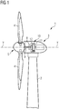
- FIG 1 shows a wind turbine 1 according to the invention.
- the wind turbine 1 comprises a tower 2, which is mounted on a non-depicted foundation.
- a nacelle 3 is arranged on top of the tower 2.
- the wind turbine 1 further comprises a wind rotor 5 having two, three or more blades 4 (in the perspective of Figure 1 only two blades 4 are visible).
- the wind rotor 5 is rotatable around a rotational axis Y.
- the terms axial, radial and circumferential in the following are made with reference to the rotational axis Y.
- the blades 4 extend radially with respect to the rotational axis Y.
- the wind turbine 1 comprises a concentrated winding electrical generator 10.
- the wind rotor 5 is rotationally coupled with the electrical generator 10 by means of a rotatable main shaft 9. According to other possible embodiments of the present invention (not represented in the attached figures), the wind rotor 5 is rotationally coupled directly with the electrical generator 10 (direct-drive generator configuration).
- a schematically depicted bearing assembly 8 is provided in order to hold in place the rotor 5.
- the rotatable main shaft 9 extends along the rotational axis Y.
- the permanent magnet electrical generator 10 includes a stator 11 and a rotor 12.
- the rotor 12 is radially external to the stator 11 and is rotatable with respect to the stator 11 about the rotational axis Y.
- the rotor is radially internal to the stator.
- the present invention can be applied to any electrical generator or motor which has concentrated winding topology, for example geared drivetrains or electrical machine of the synchronous or asynchronous types.
- the present invention can be applied to any electrical generator or motor which has a fractional slot concentrated winding.
- Figure 2 shows a schematic view of a cross section, orthogonal to the rotational axis Y, of a first embodiment of the electrical generator 10 with radially internal stator 11 and the radial external rotor 12.
- the electrical generator 10 includes a circumferential air gap 19, radially interposed between the stator 11 and the rotor 12.
- the rotor 12 includes plurality of circumferentially distributed permanent magnets 33.
- the circumferential air gap 19 is radially interposed between the permanent magnets 33 and the stator 11.
- the stator 11 includes a plurality of circumferential segments 100 (six segments 100 in the embodiment of figure 2 , each segment 100 having an angular extension about the longitudinal axis Y of 60°), which are circumferentially joined together. According to other possible embodiments of the present invention (not represented in the attached figures), the present invention and the description which follows is applied to a rotor of an electrical machine.
- Each segment 100 includes a segment body 22 circumferentially extending about the longitudinal axis Y between a first circumferential end 23a and a second circumferential 23b.
- each segment span clockwise between the respective first circumferential end 23a and the respective a second circumferential 23b.
- the segment body 22 includes a yoke 13, from which a plurality of teeth 15a, 15b, 16 and a plurality of slots 17 radially protrudes.
- the teeth 15a, 15b, 16 and the plurality of slots 17 are circumferentially distributed as follows.
- a first end tooth 15a is provided at the first circumferential end 23a and a second end tooth 15b is provided at the second circumferential ends 23b.
- Each end tooth has a first circumferential extension or thickness t1.
- the plurality of circumferential segments 100 are joined together by joining together the first end tooth 15a of one segment 100 with the second end tooth 15b of another segment 100. Any means of joining may be used.
- the plurality of intermediate teeth 16 are circumferentially distributed between the two end teeth 15a, 15b.
- Each of the plurality of N intermediate teeth 16 having a second circumferential extension or thickness t2 greater than the first circumferential extension t1.
- t2 may equal to two times of t1.
- a plurality of N+1 slots 17 i.e. thirteen slots in the embodiment of figure 2
- Each pair of circumferentially adjacent intermediate teeth 16 has a slot 17 interposed therebetween.
- a slot 17 is also provided between each end tooth 15a, 15b and a respective circumferentially adjacent intermediate tooth 16.
- the segment 100 further includes plurality of N-1 2-pitch coils 30 (i.e. eleven 2-pitch coils in the embodiment of figure 2 ).
- the coils 30 are wound according to a fractional slot winding scheme. Considering the slots being progressively counted from the first circumferential end 23a to the second circumferential end 23b, a first 2-pitch coil 30 is wound between the first slot and the third slot, a second 2-pitch coil 30 is wound between the second slot and the forth slot and so on up to the eleventh 2-pitch coil 30 that is wound between the eleventh slot and the thirteen and last slot.
- Each slot 17 extends radially so that it includes a bottom portion 17a adjacent to the yoke 13 and a top portion 17b radially opposed to the bottom portion 17a.
- the 2-pitch coils 30 extends between a top portion of the i-th slot and a bottom portion of the (i+2)-th slot. According to other embodiments of the invention (not shown) the 2-pitch coils 30 extends between a bottom portion of the i-th slot and a top portion of the (i+2)-th slot. According to other embodiments of the invention (not shown) the 2-pitch coils 30 extends between a bottom portion of the i-th slot and a bottom portion of the (i+2)-th slot.
- the 2-pitch coils 30 extends between a top portion of the i-th slot and a top portion of the (i+2)-th slot.
- the above described winding is a double-layer winding, where each slot 17 may include one coil at the bottom portion 17a and one coil at the top portion 17b.
- Each segment 100 further includes a first 1-pitch coil 31 adjacent to the first end tooth 15a and a second 1-pitch coil 31 adjacent to the second end tooth 15b.
- the first 1-pitch coil 31 is wound between the first slot and the second slot and the second slot is wound between the last ((N+1)-th) slot and the previous next to last (N-th) slot.
- the first 1-pitch coil 31 is wound between two respective bottom portions 17a of the first slot and the second slot.
- the first 1-pitch coil 31 is wound between two respective top portions 17b of the first slot and the second slot.
- the 1-pitch coil 31 may be wound between the portions of slots left free from the 2-pitch coil 30.
- the second 1-pitch coil 31 is wound between two respective top portions 17b of the last ((N+1)-th) slot and the previous next to last (N-th) slot.
- the second 1-pitch coil 31 may be wound between two respective bottom portions 17a of the last ((N+1)-th) slot and the previous next to last (N-th) slot.
- each of the thirteen slots 17 includes two 2-pitch coils 30 or one 2-pitch coil 30 and one 1-pitch coil 31. Namely, the first two slots and the last two slots includes one 2-pitch coil 30 and one 1-pitch coil 31.
- the present invention has a greater number of the permanent magnets 33 on the rotor 12.
- the increased permanent magnet 33 number i may be any integer greater than 1, i.e. i may be 2, 3....etc.
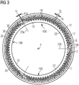
- Figure 3 shows a schematic view of a cross section, orthogonal to the rotational axis Y, of a second embodiment of the electrical generator 10.
- stator 11 may include any plurality of segments 100, i.e. two or more segments.
- the number N of intermediate teeth 16 may be any integer greater than 2, i.e. N may be 2,3....etc.
- the segment 100 includes the first end tooth 15a, the second end tooth 15b, two intermediate teeth 16, three slots 17 and one 2-pitch coil 30 extending between the first and the third (last) slot. Two 1-pitch coils respectively between the first and the second slot and between the second and the third slot may be optionally present.
Landscapes
- Engineering & Computer Science (AREA)
- Power Engineering (AREA)
- Life Sciences & Earth Sciences (AREA)
- Sustainable Energy (AREA)
- Sustainable Development (AREA)
- Chemical & Material Sciences (AREA)
- Combustion & Propulsion (AREA)
- Mechanical Engineering (AREA)
- General Engineering & Computer Science (AREA)
- Iron Core Of Rotating Electric Machines (AREA)
Abstract
It is described a stator segment (100) for the stator (11) or the rotor (12) of an electrical machine (10) including:- two end teeth (15a, 15b) at two respective circumferential ends (23a, 23b),- a plurality of N intermediate teeth (16), N being an integer greater than 1,- a plurality of N+1 slots (17) circumferentially distributed between the two end teeth (15a, 15b), each pair of circumferentially adjacent intermediate teeth (16) having a slot (17) interposed therebetween, a slot (17) being provided between each end tooth (15a, 15b) and a respective circumferentially adjacent intermediate tooth (16),- at least one 2-pitch coil (30), the 2-pitch coils (30) being in the number of N-1 and extending between an i-th slot and a (i+2)-th slot, the slots being progressively counted from one to the other of the two circumferential ends (23a, 23b), i being an integer between 1 and N-1.
Description
- The present invention relates to an electrical machine having a stator or a rotor with a segmented geometry, i.e. a stator or a rotor including a plurality of stator segments circumferentially joined together.
- In large electrical machines, segmentation of the stator and/or the rotor structure is required to ease manufacturing and transportation. This is particularly required for stators or rotors where a winding is provided. The integral slot distributed winding and fractional slot concentrated winding are two options to realize a stator or rotor structure. The integral slot distributed winding suffers from large torque ripple and the fractional slot distributed winding suffers from large rotor eddy current loss. With the purpose of achieving small torque ripple and rotor loss simultaneously, the fractional slot machine with 2-slot-pitch winding may be a potential solution. However, due to the overlapping winding structure, the stator of the conventional 2-slot-pitch winding cannot be segmented, which prevents its application in large electrical machines.
- Scope of the present invention is to provide a new segment design, for achieving the advantages above described, i.e. a segmented structure with smaller torque ripple and rotor loss in comparison with the segments designs of the prior art.
- This scope is met by the subject matter according to the independent claim. Advantageous embodiments of the present invention are described by the dependent claims.
- According to the invention, it is provided a segment for the stator or the rotor of an electrical machine including a segment body circumferentially extending about a longitudinal axis of the stator segment between two circumferential ends. The segment body includes:
- two end teeth at the two circumferential ends respectively, each end tooth having a first circumferential extension,
- a plurality of N intermediate teeth protruding according to a radial direction orthogonal to the longitudinal axis from a yoke of the segment body to respective tooth radial ends, the plurality of intermediate teeth being circumferentially distributed between the two end teeth, each of the plurality N intermediate teeth having a second circumferential extension greater than the first circumferential extension, N being an integer greater than 1,
- a plurality of N+1 slots circumferentially distributed between the two end teeth, each pair of circumferentially adjacent intermediate teeth having a slot interposed therebetween, a slot being provided between each end tooth and a respective circumferentially adjacent intermediate tooth.
- The segment further includes:
- at least one 2-pitch coil, the 2-pitch coils being in the number of N-1 and extending between an i-th slot and a (i+2)-th slot, the slots being progressively counted from one to the other of the two circumferential ends, i being an integer between 1 and N-1.
- The above described segment may be advantageously integrated in a segmented stator or rotor of an electrical machine, either generator or motor. For example, the above described segment may be advantageously integrated in the stator of an electrical generator for a wind turbine.
- According to the above described segment design of the present invention, a spatial distribution of the magnetomotive force (MMF) may be achieved which contains very low subharmonics, which leads to extremely low rotor eddy current loss in the machine. The fractional slot design of the invention achieves a significant reduction of the torque ripple in comparison with the prior art. The end coils of each segment are physically protected by the circumferential end teeth, which makes it convenient for manufacture, transport and assembly.
- According to embodiments of the invention, each slot includes a bottom portion adjacent to the yoke and a top portion radially opposed to the bottom portion, the at least one 2-pitch coil extends between a top portion of the i-th slot and a bottom portion of the (i+2)-th slot or between a bottom top portion of the i-th slot and a top portion of the (i+2)-th slot. This permits to achieve a double layer winding where torque ripple and rotor loss may be significantly reduced in comparison with conventional fractional slot winding schemes and conventional integral slot winding schemes.
- According to embodiments of the invention, the segment further includes at least one 1-pitch coil between two circumferentially adjacent slots of said plurality of N+1 slots, said at least one 1-pitch coil being adjacent to one end tooth. In particular, the at least one 1-pitch coil may extend between two respective top portions or two respective bottom portions of the two circumferentially adjacent slots of said plurality of N+1 slots. In such embodiments each slot houses two coils according to a double layer scheme, i.e. one on the top radial portion and the other on the bottom radial portion. At the circumferential ends each slot may house one 2-pitch coil and one 1-pitch coil. Alternatively, at the circumferential ends each slot may house only one 2-pitch coil, at the bottom portion or at the top portion, i.e. at the circumferential ends each slot may be half filled, while each slot between the slots at the circumferential ends houses two 2-pitch coils.
- The aspects defined above and further aspects of the present invention are apparent from the examples of embodiment to be described hereinafter and are explained with reference to the examples of embodiment. The invention will be described in more detail hereinafter with reference to examples of embodiment but to which the invention is not limited.
-
- Figure 1
- shows a schematic section of a wind turbine including an electrical generator with a stator geometry according to the present invention.
- Figure 2
- shows a cross section of an electrical generator in accordance with a first embodiment of the present invention.
- Figure 3
- shows a cross section of an electrical generator in accordance with a second embodiment of the present invention.
- The illustrations in the drawings are schematic. It is noted that in different figures, similar or identical elements are provided with the same reference signs.
-
Figure 1 shows a wind turbine 1 according to the invention. The wind turbine 1 comprises atower 2, which is mounted on a non-depicted foundation. Anacelle 3 is arranged on top of thetower 2. The wind turbine 1 further comprises a wind rotor 5 having two, three or more blades 4 (in the perspective ofFigure 1 only two blades 4 are visible). The wind rotor 5 is rotatable around a rotational axis Y. When not differently specified, the terms axial, radial and circumferential in the following are made with reference to the rotational axis Y. The blades 4 extend radially with respect to the rotational axis Y. The wind turbine 1 comprises a concentrated windingelectrical generator 10. The wind rotor 5 is rotationally coupled with theelectrical generator 10 by means of a rotatablemain shaft 9. According to other possible embodiments of the present invention (not represented in the attached figures), the wind rotor 5 is rotationally coupled directly with the electrical generator 10 (direct-drive generator configuration). A schematically depicted bearing assembly 8 is provided in order to hold in place the rotor 5. The rotatablemain shaft 9 extends along the rotational axis Y. The permanent magnetelectrical generator 10 includes astator 11 and arotor 12. Therotor 12 is radially external to thestator 11 and is rotatable with respect to thestator 11 about the rotational axis Y. According to other embodiments of the present invention (not shown) the rotor is radially internal to the stator. According to other possible embodiments of the present invention (not represented in the attached figures), the present invention can be applied to any electrical generator or motor which has concentrated winding topology, for example geared drivetrains or electrical machine of the synchronous or asynchronous types. - According to other possible embodiments of the present invention (not represented in the attached figures), the present invention can be applied to any electrical generator or motor which has a fractional slot concentrated winding.
-
Figure 2 shows a schematic view of a cross section, orthogonal to the rotational axis Y, of a first embodiment of theelectrical generator 10 with radiallyinternal stator 11 and the radialexternal rotor 12. Theelectrical generator 10 includes acircumferential air gap 19, radially interposed between thestator 11 and therotor 12. Therotor 12 includes plurality of circumferentially distributedpermanent magnets 33. Thecircumferential air gap 19 is radially interposed between thepermanent magnets 33 and thestator 11. Thestator 11 includes a plurality of circumferential segments 100 (sixsegments 100 in the embodiment offigure 2 , eachsegment 100 having an angular extension about the longitudinal axis Y of 60°), which are circumferentially joined together. According to other possible embodiments of the present invention (not represented in the attached figures), the present invention and the description which follows is applied to a rotor of an electrical machine. - Each
segment 100 includes asegment body 22 circumferentially extending about the longitudinal axis Y between a firstcircumferential end 23a and a second circumferential 23b. In the exemplary representation offigure 2 each segment span clockwise between the respective firstcircumferential end 23a and the respective a second circumferential 23b. Thesegment body 22 includes ayoke 13, from which a plurality ofteeth slots 17 radially protrudes. Theteeth slots 17 are circumferentially distributed as follows. - A
first end tooth 15a is provided at the firstcircumferential end 23a and asecond end tooth 15b is provided at the second circumferential ends 23b. Each end tooth has a first circumferential extension or thickness t1. The plurality ofcircumferential segments 100 are joined together by joining together thefirst end tooth 15a of onesegment 100 with thesecond end tooth 15b of anothersegment 100. Any means of joining may be used. A plurality of N (N=12 in the embodiment offigure 2 )intermediate teeth 16 protrude according to a radial direction orthogonal to the longitudinal axis Y from theyoke 13 to respective tooth radial ends 36. The plurality ofintermediate teeth 16 are circumferentially distributed between the twoend teeth intermediate teeth 16 having a second circumferential extension or thickness t2 greater than the first circumferential extension t1. According to possible embodiment of the present invention, t2 may equal to two times of t1. A plurality of N+1 slots 17 (i.e. thirteen slots in the embodiment offigure 2 ) are circumferentially distributed between the twoend teeth intermediate teeth 16 has aslot 17 interposed therebetween. Aslot 17 is also provided between eachend tooth intermediate tooth 16. Thesegment 100 further includes plurality of N-1 2-pitch coils 30 (i.e. eleven 2-pitch coils in the embodiment offigure 2 ). Each 2-pitch coil 30 is wound between an i-th slot and a (i+2)-th slot, i being an integer ranging between 1 and N-1 (i.e. 1=1, 2, ..., 11 in the embodiment offigure 2 ). Thecoils 30 are wound according to a fractional slot winding scheme. Considering the slots being progressively counted from the firstcircumferential end 23a to the secondcircumferential end 23b, a first 2-pitch coil 30 is wound between the first slot and the third slot, a second 2-pitch coil 30 is wound between the second slot and the forth slot and so on up to the eleventh 2-pitch coil 30 that is wound between the eleventh slot and the thirteen and last slot. - Each
slot 17 extends radially so that it includes abottom portion 17a adjacent to theyoke 13 and atop portion 17b radially opposed to thebottom portion 17a. In the embodiment offigure 2 , the 2-pitch coils 30 extends between a top portion of the i-th slot and a bottom portion of the (i+2)-th slot. According to other embodiments of the invention (not shown) the 2-pitch coils 30 extends between a bottom portion of the i-th slot and a top portion of the (i+2)-th slot. According to other embodiments of the invention (not shown) the 2-pitch coils 30 extends between a bottom portion of the i-th slot and a bottom portion of the (i+2)-th slot. According to other embodiments of the invention (not shown) the 2-pitch coils 30 extends between a top portion of the i-th slot and a top portion of the (i+2)-th slot. The above described winding is a double-layer winding, where eachslot 17 may include one coil at thebottom portion 17a and one coil at thetop portion 17b. - Each
segment 100 further includes a first 1-pitch coil 31 adjacent to thefirst end tooth 15a and a second 1-pitch coil 31 adjacent to thesecond end tooth 15b. According to above considered slot counting, the first 1-pitch coil 31 is wound between the first slot and the second slot and the second slot is wound between the last ((N+1)-th) slot and the previous next to last (N-th) slot. In the embodiment offigure 2 , the first 1-pitch coil 31 is wound between tworespective bottom portions 17a of the first slot and the second slot. According to other embodiments of the invention (not shown), the first 1-pitch coil 31 is wound between two respectivetop portions 17b of the first slot and the second slot. The 1-pitch coil 31 may be wound between the portions of slots left free from the 2-pitch coil 30. Similarly, in the embodiment offigure 2 , the second 1-pitch coil 31 is wound between two respectivetop portions 17b of the last ((N+1)-th) slot and the previous next to last (N-th) slot. Alternatively, the second 1-pitch coil 31 may be wound between tworespective bottom portions 17a of the last ((N+1)-th) slot and the previous next to last (N-th) slot. In the embodiment offigure 2 , each of the thirteenslots 17 includes two 2-pitch coils 30 or one 2-pitch coil 30 and one 1-pitch coil 31. Namely, the first two slots and the last two slots includes one 2-pitch coil 30 and one 1-pitch coil 31. - Compared with the conventional 2-slot-pitch winding with its tooth number equal to the total number of the
intermediate teeth 16, the present invention has a greater number of thepermanent magnets 33 on therotor 12. The increasedpermanent magnet 33 number i may be any integer greater than 1, i.e. i may be 2, 3....etc. -
Figure 3 shows a schematic view of a cross section, orthogonal to the rotational axis Y, of a second embodiment of theelectrical generator 10. This second embodiment differentiates itself from the first one in that thestator 11 includes threecircumferential segments 100, eachsegment 100 having an angular extension about the longitudinal axis Y of 120°, in that N= 25 and in that only 2-pitch coils 30 are wound on the teeth (no 1-pitch coils is present). Consequently, the first two slots and the last two slots includes only one 2-pitch coil 30 and are therefore only half filled. - According to other embodiments of the present invention (not shown) the stator 11 (or the rotor 12) may include any plurality of
segments 100, i.e. two or more segments. - According to other embodiments of the present invention (not shown) the number N of
intermediate teeth 16 may be any integer greater than 2, i.e. N may be 2,3....etc. In the smallest possible version of asegment 100, i.e. with N=2, thesegment 100 includes thefirst end tooth 15a, thesecond end tooth 15b, twointermediate teeth 16, threeslots 17 and one 2-pitch coil 30 extending between the first and the third (last) slot. Two 1-pitch coils respectively between the first and the second slot and between the second and the third slot may be optionally present.
Claims (12)
- Segment (100) for the stator (11) or the rotor (12) of an electrical machine (10) including a segment body (22) circumferentially extending about a longitudinal axis (Y) of the stator segment (100) between two circumferential ends (23a, 23b), the segment body (22) including:- two end teeth (15a, 15b) at the two circumferential ends (23a, 23b) respectively, each end tooth having a first circumferential extension (t1),- a plurality of N intermediate teeth (16) protruding according to a radial direction orthogonal to the longitudinal axis (Y) from a yoke (13) of the segment body (22) to respective tooth radial ends (36), the plurality of intermediate teeth (16) being circumferentially distributed between the two end teeth (15a, 15b), each of the plurality of N intermediate teeth (16) having a second circumferential extension (t2) greater than the first circumferential extension (t1), N being an integer greater than 1,- a plurality of N+1 slots (17) circumferentially distributed between the two end teeth (15a, 15b), each pair of circumferentially adjacent intermediate teeth (16) having a slot (17) interposed therebetween, a slot (17) being provided between each end tooth (15a, 15b) and a respective circumferentially adjacent intermediate tooth (16),wherein the segment (100) includes:- at least one 2-pitch coil (30), the 2-pitch coils (30) being in the number of N-1 and extending between an i-th slot and a (i+2)-th slot, the slots being progressively counted from one to the other of the two circumferential ends (23a, 23b), i being an integer between 1 and N-1.
- Segment (100) as claimed in claim 1, wherein all the slots (17) include at least one 2-pitch coil (30).
- Segment (100) as claimed in claim 1 or 2, wherein each slot (17) includes a bottom portion (17a) adjacent to the yoke (13) and a top portion (17b) radially opposed to the bottom portion (17a), the at least one 2-pitch coil (30) extends between a top portion of the i-th slot and a bottom portion of the (i+2)-th slot or between a bottom portion of the i-th slot and a top portion of the (i+2)-th slot.
- Segment (100) as claimed in claim 1 or 2, wherein each slot (17) includes a bottom portion (17a) adjacent to the yoke (13) and a top portion (17b) radially opposed to the bottom portion (17a), the at least one 2-pitch coil (30) extends between a top portion of the i-th slot and a top portion of the (i+2)-th slot or between a bottom portion of the i-th slot and a bottom portion of the (i+2)-th slot.
- Segment (100) as claimed in any of the previous claims, wherein the segment (100) further includes at least one 1-pitch coil (31) between two circumferentially adjacent slots (17) of said plurality of N+1 slots (17), said at least one 1-pitch coil (31) being adjacent to one end tooth (15a, 15b).
- Segment (100) as claimed in claim 5, wherein the at least one 1-pitch coil (31) extends between two respective top portions or two respective bottom portions of the two circumferentially adjacent slots (17) of said plurality of N+1 slots (17).
- Segment (100) as claimed in any of the previous claims, wherein the segment (100) includes a double-layer winding (30, 31) including in each of the plurality of N+1 slots (17) two 2-pitch coils (30) or one 2-pitch coil (30) and one 1-pitch coil (31).
- Segment (100) as claimed in any of the previous claims, wherein the segment (100) includes a fractional slot winding (30, 31) including said 2-pitch coils (30) and, optionally, said 1-pitch coils (31).
- Segment (100) as claimed in any of the previous claims, wherein first circumferential extension (t1) is the half of said second circumferential extension (t2).
- Stator (11) or rotor (12) for an electrical machine (10) including a plurality of segments (100) as claimed in any of the previous claims, wherein the plurality of segments (100) are circumferentially joined together in such a way that two respective end teeth (15a, 15b) are joined together.
- Electrical machine (10) including a stator (11) or rotor (12) as claimed in claim 10.
- Wind turbine (1) including an electrical generator (10) including a stator (11) or rotor (12) as claimed in claim 10.
Priority Applications (5)
| Application Number | Priority Date | Filing Date | Title |
|---|---|---|---|
| EP19204807.2A EP3813230A1 (en) | 2019-10-23 | 2019-10-23 | Electrical machine having a segmented stator or rotor |
| US17/770,065 US12149137B2 (en) | 2019-10-23 | 2020-10-09 | Electrical machine having a segmented stator or rotor |
| EP20797389.2A EP4029115B1 (en) | 2019-10-23 | 2020-10-09 | Electrical machine having a segmented stator or rotor |
| PCT/EP2020/078454 WO2021078542A1 (en) | 2019-10-23 | 2020-10-09 | Electrical machine having a segmented stator or rotor |
| CN202080074061.6A CN114556748B (en) | 2019-10-23 | 2020-10-09 | Electric motors with segmented stators or rotors |
Applications Claiming Priority (1)
| Application Number | Priority Date | Filing Date | Title |
|---|---|---|---|
| EP19204807.2A EP3813230A1 (en) | 2019-10-23 | 2019-10-23 | Electrical machine having a segmented stator or rotor |
Publications (1)
| Publication Number | Publication Date |
|---|---|
| EP3813230A1 true EP3813230A1 (en) | 2021-04-28 |
Family
ID=68342628
Family Applications (2)
| Application Number | Title | Priority Date | Filing Date |
|---|---|---|---|
| EP19204807.2A Withdrawn EP3813230A1 (en) | 2019-10-23 | 2019-10-23 | Electrical machine having a segmented stator or rotor |
| EP20797389.2A Active EP4029115B1 (en) | 2019-10-23 | 2020-10-09 | Electrical machine having a segmented stator or rotor |
Family Applications After (1)
| Application Number | Title | Priority Date | Filing Date |
|---|---|---|---|
| EP20797389.2A Active EP4029115B1 (en) | 2019-10-23 | 2020-10-09 | Electrical machine having a segmented stator or rotor |
Country Status (4)
| Country | Link |
|---|---|
| US (1) | US12149137B2 (en) |
| EP (2) | EP3813230A1 (en) |
| CN (1) | CN114556748B (en) |
| WO (1) | WO2021078542A1 (en) |
Cited By (1)
| Publication number | Priority date | Publication date | Assignee | Title |
|---|---|---|---|---|
| WO2025078109A1 (en) * | 2023-10-09 | 2025-04-17 | Asml Netherlands B.V. | Cooling and mechanical structure for a distributed wound poly-phase forcer |
Citations (2)
| Publication number | Priority date | Publication date | Assignee | Title |
|---|---|---|---|---|
| US8536754B2 (en) * | 2008-10-09 | 2013-09-17 | Feaam Gmbh | Electric motor |
| CN105680585B (en) * | 2016-02-05 | 2018-09-21 | 东南大学 | A kind of Modular motor stator and its end are overlapped fractional-slot winding structure |
Family Cites Families (7)
| Publication number | Priority date | Publication date | Assignee | Title |
|---|---|---|---|---|
| DE10394336D2 (en) * | 2003-09-11 | 2006-07-27 | Siemens Ag | Electric machine with induction rotor |
| DE102009036034B4 (en) | 2009-08-04 | 2011-07-07 | FEAAM GmbH, 85579 | Electric machine |
| DE102013103665A1 (en) * | 2013-04-11 | 2014-10-16 | Feaam Gmbh | Electric machine |
| DK2806534T3 (en) | 2013-05-23 | 2016-06-06 | Siemens Ag | Electric machine with partial parallel slots and teeth |
| CN105162271B (en) | 2015-08-21 | 2018-09-28 | 南京高传机电自动控制设备有限公司 | Stator excitation wind-driven generator |
| DE102015225586A1 (en) | 2015-12-17 | 2017-06-22 | Volkswagen Aktiengesellschaft | Bobbin for an electric coil |
| DK3557733T3 (en) | 2018-04-18 | 2021-05-31 | Siemens Gamesa Renewable Energy As | Coil formation in an electric machine with concentrated windings |
-
2019
- 2019-10-23 EP EP19204807.2A patent/EP3813230A1/en not_active Withdrawn
-
2020
- 2020-10-09 US US17/770,065 patent/US12149137B2/en active Active
- 2020-10-09 CN CN202080074061.6A patent/CN114556748B/en active Active
- 2020-10-09 EP EP20797389.2A patent/EP4029115B1/en active Active
- 2020-10-09 WO PCT/EP2020/078454 patent/WO2021078542A1/en not_active Ceased
Patent Citations (2)
| Publication number | Priority date | Publication date | Assignee | Title |
|---|---|---|---|---|
| US8536754B2 (en) * | 2008-10-09 | 2013-09-17 | Feaam Gmbh | Electric motor |
| CN105680585B (en) * | 2016-02-05 | 2018-09-21 | 东南大学 | A kind of Modular motor stator and its end are overlapped fractional-slot winding structure |
Cited By (1)
| Publication number | Priority date | Publication date | Assignee | Title |
|---|---|---|---|---|
| WO2025078109A1 (en) * | 2023-10-09 | 2025-04-17 | Asml Netherlands B.V. | Cooling and mechanical structure for a distributed wound poly-phase forcer |
Also Published As
| Publication number | Publication date |
|---|---|
| CN114556748B (en) | 2025-03-21 |
| US20220393536A1 (en) | 2022-12-08 |
| WO2021078542A1 (en) | 2021-04-29 |
| US12149137B2 (en) | 2024-11-19 |
| CN114556748A (en) | 2022-05-27 |
| EP4029115A1 (en) | 2022-07-20 |
| EP4029115B1 (en) | 2025-08-20 |
Similar Documents
| Publication | Publication Date | Title |
|---|---|---|
| EP3648305B1 (en) | Electrical machine with hybrid tooth design | |
| US11909260B2 (en) | Coil formation in an electric machine with concentrated windings | |
| US9236784B2 (en) | Flux-switching electric machine | |
| US11011948B2 (en) | Rotor, method for producing a rotor, reluctance machine, and working machine | |
| CN110337772A (en) | segmented stator motor | |
| EP4029115B1 (en) | Electrical machine having a segmented stator or rotor | |
| US11146139B2 (en) | Electric generator including a stator end plate | |
| US9843247B2 (en) | Rotating electric machine | |
| EP3703224B1 (en) | Manufacturing method for a segmented stator or rotor of an electrical machine | |
| US11955856B2 (en) | Rotary electric machine having insulating structure for rotor poles | |
| EP3811496B1 (en) | Electrical machine having a segmented stator | |
| EP3934059A1 (en) | Electrical machine having a segmented stator or rotor | |
| JP2001119874A (en) | Rotating electric machine stator | |
| JP5352442B2 (en) | Permanent magnet motor | |
| EP4443702A1 (en) | Stator segment and segmented stator for a wind turbine generator | |
| EP4329152A1 (en) | Rotor | |
| EP3989399A1 (en) | Stator or rotor segment comprising coils on teeth and adhesive anchor of outermost coil edge | |
| WO2026041250A1 (en) | Stator segment, electrical machine and wind turbine | |
| EP3389164B1 (en) | Electrical generator having reduced bearing currents | |
| EP3496233A1 (en) | Electric generator having end-windings with reduced axial protrusion |
Legal Events
| Date | Code | Title | Description |
|---|---|---|---|
| PUAI | Public reference made under article 153(3) epc to a published international application that has entered the european phase |
Free format text: ORIGINAL CODE: 0009012 |
|
| STAA | Information on the status of an ep patent application or granted ep patent |
Free format text: STATUS: THE APPLICATION HAS BEEN PUBLISHED |
|
| AK | Designated contracting states |
Kind code of ref document: A1 Designated state(s): AL AT BE BG CH CY CZ DE DK EE ES FI FR GB GR HR HU IE IS IT LI LT LU LV MC MK MT NL NO PL PT RO RS SE SI SK SM TR |
|
| AX | Request for extension of the european patent |
Extension state: BA ME |
|
| STAA | Information on the status of an ep patent application or granted ep patent |
Free format text: STATUS: THE APPLICATION IS DEEMED TO BE WITHDRAWN |
|
| 18D | Application deemed to be withdrawn |
Effective date: 20211029 |