EP3813180B1 - Secondary-battery internal gas collecting apparatus - Google Patents
Secondary-battery internal gas collecting apparatus Download PDFInfo
- Publication number
- EP3813180B1 EP3813180B1 EP20801836.6A EP20801836A EP3813180B1 EP 3813180 B1 EP3813180 B1 EP 3813180B1 EP 20801836 A EP20801836 A EP 20801836A EP 3813180 B1 EP3813180 B1 EP 3813180B1
- Authority
- EP
- European Patent Office
- Prior art keywords
- gas
- insert plate
- secondary battery
- pressing jig
- plate part
- Prior art date
- Legal status (The legal status is an assumption and is not a legal conclusion. Google has not performed a legal analysis and makes no representation as to the accuracy of the status listed.)
- Active
Links
Images




Classifications
-
- H—ELECTRICITY
- H01—ELECTRIC ELEMENTS
- H01M—PROCESSES OR MEANS, e.g. BATTERIES, FOR THE DIRECT CONVERSION OF CHEMICAL ENERGY INTO ELECTRICAL ENERGY
- H01M10/00—Secondary cells; Manufacture thereof
- H01M10/42—Methods or arrangements for servicing or maintenance of secondary cells or secondary half-cells
- H01M10/4285—Testing apparatus
-
- H—ELECTRICITY
- H01—ELECTRIC ELEMENTS
- H01M—PROCESSES OR MEANS, e.g. BATTERIES, FOR THE DIRECT CONVERSION OF CHEMICAL ENERGY INTO ELECTRICAL ENERGY
- H01M50/00—Constructional details or processes of manufacture of the non-active parts of electrochemical cells other than fuel cells, e.g. hybrid cells
- H01M50/30—Arrangements for facilitating escape of gases
- H01M50/394—Gas-pervious parts or elements
-
- G—PHYSICS
- G01—MEASURING; TESTING
- G01N—INVESTIGATING OR ANALYSING MATERIALS BY DETERMINING THEIR CHEMICAL OR PHYSICAL PROPERTIES
- G01N1/00—Sampling; Preparing specimens for investigation
- G01N1/02—Devices for withdrawing samples
- G01N1/22—Devices for withdrawing samples in the gaseous state
- G01N1/2226—Sampling from a closed space, e.g. food package, head space
-
- H—ELECTRICITY
- H01—ELECTRIC ELEMENTS
- H01M—PROCESSES OR MEANS, e.g. BATTERIES, FOR THE DIRECT CONVERSION OF CHEMICAL ENERGY INTO ELECTRICAL ENERGY
- H01M10/00—Secondary cells; Manufacture thereof
- H01M10/04—Construction or manufacture in general
- H01M10/0481—Compression means other than compression means for stacks of electrodes and separators
-
- H—ELECTRICITY
- H01—ELECTRIC ELEMENTS
- H01M—PROCESSES OR MEANS, e.g. BATTERIES, FOR THE DIRECT CONVERSION OF CHEMICAL ENERGY INTO ELECTRICAL ENERGY
- H01M10/00—Secondary cells; Manufacture thereof
- H01M10/42—Methods or arrangements for servicing or maintenance of secondary cells or secondary half-cells
- H01M10/52—Removing gases inside the secondary cell, e.g. by absorption
-
- H—ELECTRICITY
- H01—ELECTRIC ELEMENTS
- H01M—PROCESSES OR MEANS, e.g. BATTERIES, FOR THE DIRECT CONVERSION OF CHEMICAL ENERGY INTO ELECTRICAL ENERGY
- H01M50/00—Constructional details or processes of manufacture of the non-active parts of electrochemical cells other than fuel cells, e.g. hybrid cells
- H01M50/10—Primary casings; Jackets or wrappings
- H01M50/102—Primary casings; Jackets or wrappings characterised by their shape or physical structure
- H01M50/105—Pouches or flexible bags
-
- H—ELECTRICITY
- H01—ELECTRIC ELEMENTS
- H01M—PROCESSES OR MEANS, e.g. BATTERIES, FOR THE DIRECT CONVERSION OF CHEMICAL ENERGY INTO ELECTRICAL ENERGY
- H01M50/00—Constructional details or processes of manufacture of the non-active parts of electrochemical cells other than fuel cells, e.g. hybrid cells
- H01M50/10—Primary casings; Jackets or wrappings
- H01M50/116—Primary casings; Jackets or wrappings characterised by the material
- H01M50/124—Primary casings; Jackets or wrappings characterised by the material having a layered structure
-
- H—ELECTRICITY
- H01—ELECTRIC ELEMENTS
- H01M—PROCESSES OR MEANS, e.g. BATTERIES, FOR THE DIRECT CONVERSION OF CHEMICAL ENERGY INTO ELECTRICAL ENERGY
- H01M50/00—Constructional details or processes of manufacture of the non-active parts of electrochemical cells other than fuel cells, e.g. hybrid cells
- H01M50/10—Primary casings; Jackets or wrappings
- H01M50/131—Primary casings; Jackets or wrappings characterised by physical properties, e.g. gas permeability, size or heat resistance
- H01M50/136—Flexibility or foldability
-
- H—ELECTRICITY
- H01—ELECTRIC ELEMENTS
- H01M—PROCESSES OR MEANS, e.g. BATTERIES, FOR THE DIRECT CONVERSION OF CHEMICAL ENERGY INTO ELECTRICAL ENERGY
- H01M50/00—Constructional details or processes of manufacture of the non-active parts of electrochemical cells other than fuel cells, e.g. hybrid cells
- H01M50/10—Primary casings; Jackets or wrappings
- H01M50/183—Sealing members
- H01M50/184—Sealing members characterised by their shape or structure
-
- H—ELECTRICITY
- H01—ELECTRIC ELEMENTS
- H01M—PROCESSES OR MEANS, e.g. BATTERIES, FOR THE DIRECT CONVERSION OF CHEMICAL ENERGY INTO ELECTRICAL ENERGY
- H01M50/00—Constructional details or processes of manufacture of the non-active parts of electrochemical cells other than fuel cells, e.g. hybrid cells
- H01M50/30—Arrangements for facilitating escape of gases
-
- H—ELECTRICITY
- H01—ELECTRIC ELEMENTS
- H01M—PROCESSES OR MEANS, e.g. BATTERIES, FOR THE DIRECT CONVERSION OF CHEMICAL ENERGY INTO ELECTRICAL ENERGY
- H01M50/00—Constructional details or processes of manufacture of the non-active parts of electrochemical cells other than fuel cells, e.g. hybrid cells
- H01M50/30—Arrangements for facilitating escape of gases
- H01M50/35—Gas exhaust passages comprising elongated, tortuous or labyrinth-shaped exhaust passages
-
- H—ELECTRICITY
- H01—ELECTRIC ELEMENTS
- H01M—PROCESSES OR MEANS, e.g. BATTERIES, FOR THE DIRECT CONVERSION OF CHEMICAL ENERGY INTO ELECTRICAL ENERGY
- H01M50/00—Constructional details or processes of manufacture of the non-active parts of electrochemical cells other than fuel cells, e.g. hybrid cells
- H01M50/30—Arrangements for facilitating escape of gases
- H01M50/35—Gas exhaust passages comprising elongated, tortuous or labyrinth-shaped exhaust passages
- H01M50/358—External gas exhaust passages located on the battery cover or case
-
- G—PHYSICS
- G01—MEASURING; TESTING
- G01N—INVESTIGATING OR ANALYSING MATERIALS BY DETERMINING THEIR CHEMICAL OR PHYSICAL PROPERTIES
- G01N1/00—Sampling; Preparing specimens for investigation
- G01N1/02—Devices for withdrawing samples
- G01N1/22—Devices for withdrawing samples in the gaseous state
- G01N1/2226—Sampling from a closed space, e.g. food package, head space
- G01N2001/2238—Sampling from a closed space, e.g. food package, head space the gas being compressed or pressurized
-
- Y—GENERAL TAGGING OF NEW TECHNOLOGICAL DEVELOPMENTS; GENERAL TAGGING OF CROSS-SECTIONAL TECHNOLOGIES SPANNING OVER SEVERAL SECTIONS OF THE IPC; TECHNICAL SUBJECTS COVERED BY FORMER USPC CROSS-REFERENCE ART COLLECTIONS [XRACs] AND DIGESTS
- Y02—TECHNOLOGIES OR APPLICATIONS FOR MITIGATION OR ADAPTATION AGAINST CLIMATE CHANGE
- Y02E—REDUCTION OF GREENHOUSE GAS [GHG] EMISSIONS, RELATED TO ENERGY GENERATION, TRANSMISSION OR DISTRIBUTION
- Y02E60/00—Enabling technologies; Technologies with a potential or indirect contribution to GHG emissions mitigation
- Y02E60/10—Energy storage using batteries
-
- Y—GENERAL TAGGING OF NEW TECHNOLOGICAL DEVELOPMENTS; GENERAL TAGGING OF CROSS-SECTIONAL TECHNOLOGIES SPANNING OVER SEVERAL SECTIONS OF THE IPC; TECHNICAL SUBJECTS COVERED BY FORMER USPC CROSS-REFERENCE ART COLLECTIONS [XRACs] AND DIGESTS
- Y02—TECHNOLOGIES OR APPLICATIONS FOR MITIGATION OR ADAPTATION AGAINST CLIMATE CHANGE
- Y02P—CLIMATE CHANGE MITIGATION TECHNOLOGIES IN THE PRODUCTION OR PROCESSING OF GOODS
- Y02P70/00—Climate change mitigation technologies in the production process for final industrial or consumer products
- Y02P70/50—Manufacturing or production processes characterised by the final manufactured product
Definitions
- a secondary battery is a battery which can be repeatedly used through a discharging process converting chemical energy into electrical energy and a reverse process, a charging process, and includes, as its kind, a nickelcadmium (Ni-Cd) battery, a nickel-hydrogen (Ni-MH) battery, a lithium-metal battery, a lithium-ion (Li-ion) battery, a lithium-ion polymer battery, etc.
- the lithium secondary batteries which have a high energy density and voltage, a long cycle life and a low selfdischarge rate, have been commercialized and widely used.
- the lithium secondary battery is degraded as a large amount of gas is generated by the decomposition of an electrolyte according to repeated charging and discharging progresses, and this phenomenon appears differently depending on the design and use type of the battery. Therefore, analyzing the gas generated inside the battery to infer the degradation mechanism of the battery should essentially be performed in the development process of the battery.
- the secondary battery in order to collect the gas generated in the secondary battery, the secondary battery was placed in a closed space, which was depressurized under vacuum, and then, a hole was drilled in the secondary battery to diffuse the generated gas into the closed space accommodating the secondary battery, and then, a sample was taken. Therefore, a jig is needed to enclose the entire exterior of the secondary battery to form a closed space for accommodating the secondary battery, and this jig is required to have a form conforming to the specification and shape of each different type of the secondary batteries released for various purposes (EV, ESS, mobile phone, etc.). That is, in the conventional gas collecting apparatus, since the secondary battery has various specifications such as area, thickness, etc., it is necessary to replace the jig whenever the shape and specification of the secondary battery to be inspected are changed.
- Korean Laid-Open Patent Publication No. 10-2018-0047274 discloses a technique concerned with 'an apparatus and a method for collecting gas generated in a secondary battery'.
- a pressing jig part of the gas-collecting apparatus of the present invention only needs to press an area equal to that of the insert plate part, and thus, contacts and presses only a local area of a secondary battery. Therefore, even if the jig is coupled to the secondary battery, the secondary battery has an exposed area that is not coupled to the jig. This exposed area can be used to connect accessory parts for various analyses.
- the insert plate part may include a gas flow path connected to the through hole from an edge of the insert plate part.
- the jig fixing mean may be provided in plural; the jig fixing means may include a first jig fixing mean and a second jig fixing mean; and a virtual straight line connecting two points through which the first jig fixing mean and the second jig fixing mean pass on a virtual plane including the insert plate part between the pressing jig part and the supporting jig part may penetrate the insert plate part.
- the gas-collecting apparatus of the present invention comprises: an insert plate part 100 in close contact with the first sheet 13a inside the pouch case 13; a pressing jig part 200 in close contact with the insert plate part 100 outside the pouch case 13 with the first sheet 13a interposed therebetween; a punching part 400 for drilling a ventilating hole in the pouch case 13 wherein the ventilating hole allows the gas generated inside the secondary battery 10 to be discharged to the outside of the pouch case 13; and a supporting jig part 300 facing and being in close contact with the pressing jig part 200, with the secondary battery 10 interposed therebetween, outside the pouch case 13.
- the through hole 110 is a passage through which the internal gas of the secondary battery 10 moves.
- the gas introduced into the second surface 103 of the insert plate part 100 through the through hole 110 is discharged to the first surface 101, and the gas may be delivered to an external analysis apparatus.
- a ventilating hole is formed in the pouch case 13 by inserting a needle 410 into the through hole 110 of the insert plate part 100 located inside the pouch case 13 from the outside of the pouch case 13. That is, the through hole 110 is a passage through which the gas moves, while also being a guide for forming a ventilating hole.
- a pressing jig part 200 of the gas-collecting apparatus of the present invention only needs to press an area equal to that of the insert plate part 100, and thus, contacts and presses only a local area of the secondary battery 10. Therefore, even if the jig is coupled to the secondary battery 10, the secondary battery 10 has an exposed area that is not coupled to the jig.
- This exposed area can be used to connect accessory parts for various analyses.
- the accessory parts may be a pressing jig, an insulating material, or the like.
- the gas-collecting apparatus of the present invention can be utilized for batteries of all sizes regardless of the specifications such as the area, thickness, etc. of the secondary battery 10.
- a gas moving path 210 of which one end is connected to the through hole 110 and through which the gas generated in the secondary battery 10 flows is formed inside the pressing jig part 200.
- An inlet of the gas moving path 210 may be formed on a surface facing the pouch case 13. Specifically, the inlet of the gas moving path 210 may be formed at a position facing the through hole 110 of the insert plate part 100 among the surfaces facing the pouch case 13. Therefore, the gas discharged through the through hole 110 may directly flow into the inlet of the gas moving path 210.
- the gas moving path 210 may be formed to discharge the gas to the side surface of the pressing jig part 200 via the inside of the pressing jig part 200.
Landscapes
- Chemical & Material Sciences (AREA)
- Chemical Kinetics & Catalysis (AREA)
- Electrochemistry (AREA)
- General Chemical & Material Sciences (AREA)
- Engineering & Computer Science (AREA)
- Manufacturing & Machinery (AREA)
- Health & Medical Sciences (AREA)
- Life Sciences & Earth Sciences (AREA)
- Physics & Mathematics (AREA)
- Molecular Biology (AREA)
- Biomedical Technology (AREA)
- Analytical Chemistry (AREA)
- Biochemistry (AREA)
- General Health & Medical Sciences (AREA)
- General Physics & Mathematics (AREA)
- Immunology (AREA)
- Pathology (AREA)
- Sampling And Sample Adjustment (AREA)
- Gas Exhaust Devices For Batteries (AREA)
- Secondary Cells (AREA)
Description
- This application claims the benefit of priority to
Korean Patent Application No. 10-2019-0052956 filed on May 7, 2019 - The present invention relates to a gas-collecting apparatus for collecting gas in a secondary battery, and more particularly, to a gas-collecting apparatus capable of easily collecting gas inside a secondary battery regardless of the standard dimension and the shape of the secondary battery.
- In general, a secondary battery is a battery which can be repeatedly used through a discharging process converting chemical energy into electrical energy and a reverse process, a charging process, and includes, as its kind, a nickelcadmium (Ni-Cd) battery, a nickel-hydrogen (Ni-MH) battery, a lithium-metal battery, a lithium-ion (Li-ion) battery, a lithium-ion polymer battery, etc. Among these secondary batteries, the lithium secondary batteries, which have a high energy density and voltage, a long cycle life and a low selfdischarge rate, have been commercialized and widely used.
- Various kinds of gases, such as hydrogen, oxygen, nitrogen, carbon monoxide, carbon dioxide, hydrocarbons such as CnH2n-2 (n=2~5) , CnH2n (n=2-5) and CnH2n+2 (n=1~5), other organic gas species, etc. may be generated depending on the reaction in the lithium secondary battery.
- In addition, the lithium secondary battery is degraded as a large amount of gas is generated by the decomposition of an electrolyte according to repeated charging and discharging progresses, and this phenomenon appears differently depending on the design and use type of the battery. Therefore, analyzing the gas generated inside the battery to infer the degradation mechanism of the battery should essentially be performed in the development process of the battery.
- Therefore, it is very important to collect and accurately analyze the gas generated in the secondary battery. Various gases are generated during operation of the lithium ion battery, and information on the composition and content of the generated gases is useful for the development of battery materials, optimization of battery manufacturing processes, and identification of causes of battery defects. To this end, it is important to develop a technology for collecting the gas generated inside the secondary battery.
- Conventionally, in order to collect the gas generated in the secondary battery, the secondary battery was placed in a closed space, which was depressurized under vacuum, and then, a hole was drilled in the secondary battery to diffuse the generated gas into the closed space accommodating the secondary battery, and then, a sample was taken. Therefore, a jig is needed to enclose the entire exterior of the secondary battery to form a closed space for accommodating the secondary battery, and this jig is required to have a form conforming to the specification and shape of each different type of the secondary batteries released for various purposes (EV, ESS, mobile phone, etc.). That is, in the conventional gas collecting apparatus, since the secondary battery has various specifications such as area, thickness, etc., it is necessary to replace the jig whenever the shape and specification of the secondary battery to be inspected are changed.
-
Korean Laid-Open Patent Publication No. 10-2018-0047274 -
Document KR 101 641 617 B1 KR 2016 0072571 A - The invention is defined in the independent claim. Embodiments of the invention are defined in the dependent claims.
- It is an object of the present invention to provide a gas-collecting apparatus for collecting gas in a secondary battery, and more particularly, a gas-collecting apparatus capable of easily collecting gas inside a secondary battery regardless of the specification and shape of the secondary battery.
- The technical problems to be solved by the present invention are not limited to the technical problems as mentioned above, and other technical problems not mentioned will be clearly understood from the following description by those skilled in the art to which the present invention pertains.
- A gas-collecting apparatus for a secondary battery of the present invention is the apparatus for collecting gas generated in a secondary battery comprising an electrode assembly and a flexible pouch case accommodating the electrode assembly therein, wherein the pouch case includes a first sheet covering one surface of the electrode assembly and a second sheet covering the other surface of the electrode assembly, the apparatus comprises: an insert plate part in close contact with the first sheet inside the pouch case; and a pressing jig part in close contact with the insert plate part outside the pouch case with the first sheet interposed therebetween, wherein the insert plate part may include a through hole penetrating the insert plate part so that a first surface of the insert plate part facing the first sheet and a second surface opposite to the first surface are connected to each other; and a gas moving path of which one end is connected to the through hole and through which the gas generated in the secondary battery flows may be formed inside the pressing jig part.
- The gas-collecting apparatus for a secondary battery of the present invention can be utilized consistently for secondary batteries of all sizes regardless of a change in the specifications of the batteries.
- The gas-collecting apparatus of the present invention immediately collects gas inside a pouch case without requiring a process of diffusing the gas in a separate chamber, thereby reducing a space for gas diffusion. Therefore, since the gas generated in the secondary battery can be collected in a smaller space, it is possible to increase the efficiency of analysis by collecting a high concentration of gas.
- A pressing jig part of the gas-collecting apparatus of the present invention only needs to press an area equal to that of the insert plate part, and thus, contacts and presses only a local area of a secondary battery. Therefore, even if the jig is coupled to the secondary battery, the secondary battery has an exposed area that is not coupled to the jig. This exposed area can be used to connect accessory parts for various analyses.
- The gas-collecting apparatus of the present invention securely fixes only a portion of the secondary battery with a pressing jig part and an insert plate part, and therefore, even if the shape and size of the secondary battery changes during the analysis, it is possible to smoothly collect the gas.
- Even if the gas-collecting apparatus of the present invention is damaged by ignition of the secondary battery, only an insert plate part or a pressing jig part needs to be replaced, thereby reducing the maintenance cost of the apparatus.
- In the case of an O-ring applied to the structure of the gas-collecting apparatus of the present invention, its area is 2 to 1000 times smaller than that of the O-ring used in the conventional collecting apparatuses, thereby effectively improving leakage due to the O-ring.
-
-
Fig. 1 is a side view showing a gas-collecting apparatus of the present invention. -
Fig. 2 is a side view showing a gas-collecting apparatus of another embodiment of the present invention. -
Fig. 3 is a perspective view showing a first surface of an insert plate part. -
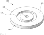
Fig. 4 is a perspective view showing a second surface of an insert plate part. -
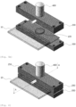
Fig. 5A is a perspective view showing a pressing jig part of a gas-collecting apparatus of the present invention before pressing a secondary battery. -
Fig. 5B is a perspective view showing a state that a pressing jig part of a gas-collecting apparatus of the present invention presses a secondary battery. -
Fig. 6 is a cross-sectional view showing a cross-section A-A inFig. 5B . -
Fig. 7 is a conceptual view showing a coupled relationship between a fixing means and a pressing jig part. -
Fig. 8 is a cross-sectional view showing a gas moving path in a gas-collecting apparatus of the present invention. - A gas-collecting apparatus of the present invention is the apparatus for collecting gas generated in a secondary battery comprising an electrode assembly and a flexible pouch case accommodating the electrode assembly therein, wherein when the pouch case includes a first sheet covering one side surface of the electrode assembly and a second sheet covering the other side surface of the electrode assembly, the apparatus comprises: an insert plate part in close contact with the first sheet inside the pouch case; and a pressing jig part in close contact with the insert plate part outside the pouch case with the first sheet interposed therebetween, wherein the insert plate part includes a through hole penetrating the insert plate part so that a first surface of the insert plate part facing the first sheet and a second surface opposite to the first surface are connected to each other; and a gas moving path of which one end is connected to the through hole and through which the gas generated in the secondary battery flows may be formed inside the pressing jig part.
- In the gas-collecting apparatus of the present invention, it is further included a punching part inserted into the through hole from the outside of the pouch case for forming a ventilating hole in the first sheet, wherein the ventilating hole allows the gas to be discharged to the outside of the pouch case and to flow into the gas moving path.
- In the gas-collecting apparatus of the present invention, the punching part may be coupled to a surface of the pressing jig part opposite to a surface of the pressing jig part contacting the secondary battery; and a needle hole penetrating the inside of the pressing jig part may be formed in the pressing jig part so that a needle provided in the punching part protrudes to a surface of the pressing jig part contacting the secondary battery.
- In the gas-collecting apparatus of the present invention, a sealing groove having a closed curve shape in which the through hole is placed inside may be formed on the first surface of the insert plate part or on a surface of the pressing jig part in close contact with the first sheet; and a first sealing member made of an elastic material may be inserted into the sealing groove to prevent the gas from leaking into a contacting surface between the first sheet and the pressing jig part.
- In the gas-collecting apparatus of the present invention, the first sealing member may be an O-ring.
- In the gas-collecting apparatus of the present invention, the insert plate part may include a gas flow path connected to the through hole from an edge of the insert plate part.
- In the gas-collecting apparatus of the present invention, the gas flow path may be formed by a groove extending from the through hole to an edge of the insert plate part on the second surface of the insert plate part; the gas flow path may be provided in plural; and the plurality of gas flow paths may be disposed radially symmetrically around the through hole.
- The gas-collecting apparatus of the present invention further includes a supporting jig part facing and being in close contact with the pressing jig part, with the secondary battery interposed therebetween, outside the pouch case.
- The gas-collecting apparatus of the present invention may further include a jig fixing mean connected to the pressing jig part and the supporting jig part to fix a relative position between the pressing jig part and the supporting jig part in a state that the pressing jig part and the supporting jig part are in close contact with the secondary battery interposed therebetween.
- In the gas-collecting apparatus of the present invention, the jig fixing mean may be provided in plural; the jig fixing means may include a first jig fixing mean and a second jig fixing mean; and a virtual straight line connecting two points through which the first jig fixing mean and the second jig fixing mean pass on a virtual plane including the insert plate part between the pressing jig part and the supporting jig part may penetrate the insert plate part.
- Hereinafter, embodiments according to the present invention will be described in detail with reference to the accompanying drawings. In the description, the size, shape or the like of elements shown in the drawings may be exaggerated for clarity and convenience of the description. In addition, terms specifically defined in consideration of the constitution and function of the present invention may vary depending on the intention or practice of a user or operator. Definitions of these terms should be made based on the contents disclosed throughout this specification.
- In the description of the present invention, it should be noted that a directional or positional relationship indicated by the terms "center", "upper", "lower", "left", "right", "vertical", "horizontal", "inside", "outside", etc. is based on a directional or positional relationship shown in the drawings, or a directional or positional relationship that is usually arranged when using the product of the present invention; and such directional or positional relationship is only for the illustration and concise description of the present invention and does not necessarily suggest or imply that the indicated apparatus or element must have a specified direction and must be constructed or manipulated with the specified direction, and thus, should not be construed as limiting the present invention.
- Hereinafter, the configuration and function of the gas-collecting apparatus of the present invention will be described in detail with reference to
Figs. 1 to 8 . -
Fig. 1 is a side view showing a gas-collecting apparatus of the present invention.Fig. 2 is a side view showing a gas-collecting apparatus of another embodiment of of the present invention.Fig. 3 is a perspective view showing a first surface of an insert plate part.Fig. 4 is a perspective view showing a second surface of an insert plate part.Fig. 5A is a perspective view showing a pressing jig part of a gas-collecting apparatus of the present invention before pressing a secondary battery.Fig. 5B is a perspective view showing a state that a pressing jig part of a gas-collecting apparatus of the present invention presses a secondary battery.Fig. 6 is a cross-sectional view showing a cross-section A-A inFig. 5B .Fig. 7 is a conceptual view showing a coupled relationship between a fixing means and a pressing jig part.Fig. 8 is a cross-sectional view showing a gas moving path in a gas-collecting apparatus of the present invention. - The gas-collecting apparatus of the present invention may be the apparatus for collecting gas generated in a
secondary battery 10 comprising anelectrode assembly 11 and aflexible pouch case 13 accommodating theelectrode assembly 11 therein. That is, the gas-collecting apparatus of the present invention may be applied to thesecondary battery 10 in which thepouch case 13 forming an outer shape is made of an easily deformable material. For example, thepouch case 13 may be an aluminum pouch (Al pouch). Although the gas-collecting apparatus of the present invention may also be applied to asecondary battery 10 having a rigid case, it may be more effective for asecondary battery 10 in which aflexible pouch case 13 forms the exterior. In the case of theflexible pouch case 13, its volume may be changed according to a variation in the internal and external pressure of thesecondary battery 10. The gas-collecting apparatus of the present invention securely fixes only a portion of thesecondary battery 10 with apressing jig part 200 and aninsert plate part 100, and therefore, even if the shape and size of thesecondary battery 10 are changed during analysis, gas collection can be smoothly performed. - As shown in
Figs. 1 and 2 , when thepouch case 13 includes afirst sheet 13a covering one side surface of theelectrode assembly 11 and a second sheet 13b covering the other side surface of theelectrode assembly 11, the gas-collecting apparatus of the present invention comprises: aninsert plate part 100 in close contact with thefirst sheet 13a inside thepouch case 13; apressing jig part 200 in close contact with theinsert plate part 100 outside thepouch case 13 with thefirst sheet 13a interposed therebetween; a punchingpart 400 for drilling a ventilating hole in thepouch case 13 wherein the ventilating hole allows the gas generated inside thesecondary battery 10 to be discharged to the outside of thepouch case 13; and a supportingjig part 300 facing and being in close contact with thepressing jig part 200, with thesecondary battery 10 interposed therebetween, outside thepouch case 13. -
Fig. 1 shows an embodiment in which aninsert plate part 100 is positioned to directly contact thefirst sheet 13a and the second sheet 13b of thepouch case 13.Fig. 2 shows another embodiment in which theinsert plate part 100 is positioned such that one side surface of theinsert plate part 100 contacts with an inner surface of thepouch case 13, while the other side surface contacts with theelectrode assembly 11. Thepouch case 13 may be made larger than theelectrode assembly 11, and in this case, theelectrode assembly 11 may not be present near an edge of thepouch case 13. Therefore, in the center region of thesecondary battery 10, thefirst sheet 13a-electrode assembly 11-second sheet 13b may be stacked in the order, whereas in the edge region, the first sheet-second sheet 13b may be stacked in the order. The position of theinsert plate part 100 may be selectively determined by physical properties of thepouch case 13, experimental conditions, the shape of theelectrode assembly 11, and the like. The position of theinsert plate part 100 may be determined according to the analysis situation and conditions without limitation within thepouch case 13. However, in order to minimize the effect of the electrode, theinsert plate part 100 may be positioned at a position spaced apart from the electrode by a certain distance so as to avoid contact with the electrode. - The
insert plate part 100 is in close contact with an externalpressing jig part 200 inside thepouch case 13, whereby the gas generated in thesecondary battery 10 can be moved without leakage to agas moving path 210 provided inside thepressing jig part 200. Theinsert plate part 100 may be a disc-shaped plate having a thickness. - The
insert plate part 100 is made of a material having properties such as corrosion resistance, heat resistance, abrasion resistance and chemical resistance, and the material of theinsert plate part 100 may include one or more of teflon and bakelite as a polymeric insulating material. Theinsert plate part 100 is directly exposed to the gas generated in thesecondary battery 10, and may have a path through which the gas passes. Therefore, if damage such as corrosion, wear, deterioration, deformation, etc. occurs in theinsert plate part 100, a flow path for gas collection may be blocked or the generated gas may leak out. If the component separated from theinsert plate part 100 is mixed with the gas, it may affect the analysis results. - The
insert plate part 100 may be inserted during or after the manufacturing process of thesecondary battery 10, and may not affect the manufacturing and activation process of thesecondary battery 10, and the like. - As shown in
Figs. 3 and4 , theinsert plate part 100 includes a throughhole 110 penetrating theinsert plate part 100 so that afirst surface 101 of theinsert plate part 100 facing thefirst sheet 13a and asecond surface 103 opposite to thefirst surface 101 are connected to each other. For example, the throughhole 110 may be provided to form a passage in a direction perpendicular to a surface of theinsert plate part 100. - The through
hole 110 is a passage through which the internal gas of thesecondary battery 10 moves. The gas introduced into thesecond surface 103 of theinsert plate part 100 through the throughhole 110 is discharged to thefirst surface 101, and the gas may be delivered to an external analysis apparatus. In addition, a ventilating hole is formed in thepouch case 13 by inserting aneedle 410 into the throughhole 110 of theinsert plate part 100 located inside thepouch case 13 from the outside of thepouch case 13. That is, the throughhole 110 is a passage through which the gas moves, while also being a guide for forming a ventilating hole. - As shown in
Fig. 3 , a sealinggroove 120 having a closed curve shape in which the throughhole 110 is placed inside may be formed on thefirst surface 101 of theinsert plate part 100. For example, the sealinggroove 120 may be formed of a circular ring, and the throughhole 110 may be located in the center of the ring. The shape and size of the sealinggroove 120 may be the same as those of the first sealing member inserted into the sealinggroove 120. For example, if an O-ring as a first sealing member is inserted into the sealinggroove 120, the sealinggroove 120 may have the same shape as that of the O-ring. The sealinggroove 120 may also be formed on a surface of thepressing jig part 200 in close contact with thefirst sheet 13a, or may be provided in both theinsert plate part 100 and thepressing jig part 200. - A first sealing member made of an elastic material is inserted into the sealing
groove 120 to prevent gas from leaking into a contacting surface between thefirst sheet 13a and thepressing jig unit 200. The first sealing member may be an O-ring. Specifically, in a state that theinsert plate part 100 is inserted into thepouch case 13 so that thefirst surface 101 of theinsert plate part 100 contacts with thefirst sheet 13a, the first sealing member is disposed at the position of the sealinggroove 120 outside thepouch case 13, and then, the first sealing member may be pressed by thepressing jig part 200 so as to be inserted into the sealinggroove 120. The first sealing member is inserted into the sealinggroove 120, whereby thepouch case 13 between the first sealing member and the sealinggroove 120 may also be pressed and inserted. When the first sealing member is pressed by thepressing jig part 200, it may be deformed to fill and seal a gap between the first sealing member and thefirst sheet 13a and a gap between the first sealing member and thepressing jig part 200. - In the case of an O-ring applied to the structure of the gas-collecting apparatus of the present invention, its area is 2 to 1000 times smaller than that of the O-ring used in the conventional collecting apparatuses, thereby effectively improving leakage due to the O-ring.
- As shown in
Fig. 4 , theinsert plate part 100 may include agas flow path 130 connected from an edge of theinsert plate part 100 to the throughhole 110. Specifically, thegas flow path 130 may be formed by a groove extending from the throughhole 110 to the edge of theinsert plate part 100 on thesecond surface 103 of theinsert plate part 100. Thegas flow path 130 may be provided in plural, and the plurality ofgas flow paths 130 may be disposed radially symmetrically around the throughhole 110. For example, one end of thegas flow path 130 may be connected to the throughhole 110 formed in the center of the disk-shapedinsert plate part 100, and the other end may be connected to the edge of theinsert plate part 100. That is, theinsert plate part 100 may have the sealinggroove 120 formed on thefirst surface 101, thegas flow path 130 formed on thesecond surface 103, and the throughhole 110 formed to connect thefirst surface 101 and thesecond surface 103. - As shown in
Figs. 5A and 5B , thepressing jig part 200 presses theinsert plate part 100 inside thepouch case 13 from the outside of thepouch case 13. Thepressing jig part 200 presses theinsert plate part 100, whereby a sealing is made to prevent gas from leaking to the outside, and at the same time, the relative position between theinsert plate part 100 and the punchingpart 400 forming a ventilating hole in thepouch case 13 are fixed, so that the throughhole 110 and the ventilating hole are formed in a position to face each other. - A
pressing jig part 200 of the gas-collecting apparatus of the present invention only needs to press an area equal to that of theinsert plate part 100, and thus, contacts and presses only a local area of thesecondary battery 10. Therefore, even if the jig is coupled to thesecondary battery 10, thesecondary battery 10 has an exposed area that is not coupled to the jig. This exposed area can be used to connect accessory parts for various analyses. For example, the accessory parts may be a pressing jig, an insulating material, or the like. - The gas-collecting apparatus of the present invention can be utilized for batteries of all sizes regardless of the specifications such as the area, thickness, etc. of the
secondary battery 10. - As shown in
Fig. 6 , agas moving path 210 of which one end is connected to the throughhole 110 and through which the gas generated in thesecondary battery 10 flows is formed inside thepressing jig part 200. An inlet of thegas moving path 210 may be formed on a surface facing thepouch case 13. Specifically, the inlet of thegas moving path 210 may be formed at a position facing the throughhole 110 of theinsert plate part 100 among the surfaces facing thepouch case 13. Therefore, the gas discharged through the throughhole 110 may directly flow into the inlet of thegas moving path 210. Thegas moving path 210 may be formed to discharge the gas to the side surface of thepressing jig part 200 via the inside of thepressing jig part 200. That is, an outlet of thegas moving path 210 may be formed on the side surface of thepressing jig part 200. The outlet of thegas moving path 210 may be formed on any surface of thepressing jig part 200, but may be preferably formed on the side surface of thepressing jig part 200 in consideration of the arrangement with other parts. A pipe, such as a hose, through which a fluid can move may be connected to the outlet of thegas moving path 210 to transfer the gas to an external analysis apparatus. However, when ignition of the battery is expected, the punching part may be separated from the pressing jig part in order to prevent damage to the punching part after forming a ventilating hole in the pouch case. In this case, the outlet of thegas moving path 210 may be formed at a position where the punching part is coupled, not at the side surface of the pressing jig part. - The punching
part 400 is inserted into the throughhole 110 from the outside of thepouch case 13 to form a ventilating hole in thefirst sheet 13a wherein the ventilating hole allows the gas to be discharged to the outside of thepouch case 13 and to flow into thegas moving path 210. The punchingpart 400 is coupled to a surface of thepressing jig part 200 opposite to a surface of thepressing jig part 200 contacting thesecondary battery 10; and aneedle hole 220 penetrating the inside of the pressing jig part may be formed in thepressing jig part 200 so that aneedle 410 provided in the punchingpart 400 protrudes to the surface of thepressing jig part 200 contacting thesecondary battery 10. - As shown in
Fig. 6 , the punchingpart 400 may include aneedle 410 for drilling a hole in the pouch, abody part 420 having one end to which theneedle 410 is fixed and having a diameter larger than a diameter of theneedle 410, a button (not shown) connected to the other end of thebody part 420 to press thebody part 420, and an elastic member (not shown) providing a restoring force for thebody part 420 to move thebody part 420 to its original position after thebody part 420 is pressed, and a stopper (not shown) that restricts the upper or lower limit of the reciprocating motion of thebody part 420. - A portion of the
body part 420 is inserted into theneedle hole 220 formed in thepressing jig part 200, and thebody part 420 may reciprocate along theneedle hole 220. Theneedle hole 220 is formed to penetrate thepressing jig part 200 in a direction perpendicular to a surface of thepressing jig part 200 facing thepouch case 13, and thebody part 420 may be inserted into a surface opposite to a surface of thepressing jig part 200 facing thepouch case 13. A diameter of some sections of theneedle hole 220 into which thebody part 420 is inserted is formed to be substantially the same as a diameter of thebody part 420, and a second sealing member (not shown) may be inserted into an inner surface of theneedle hole 220 and a side surface of thebody part 420. A groove into which the second sealing member is inserted may be formed in thebody part 420. - The
needle 410 protrudes to an inlet of theneedle hole 220 formed on a surface of thepressing jig part 200 facing thepouch case 13 to form a ventilating hole in thepouch case 13. The inlet of theneedle hole 220 formed on the surface of thepressing jig part 200 facing thepouch case 13 may be the same hole as an inlet of thegas moving path 210. That is, theneedle hole 220 and thegas moving path 210 may share some sections. - The gas-collecting apparatus of the present invention may further include a jig fixing mean 500 connected to the
pressing jig part 200 and the supportingjig part 300 to fix the relative position between thepressing jig part 200 and the supportingjig part 300 in a state that thepressing jig part 200 and the supportingjig part 300 are in close contact with thesecondary battery 10 interposed therebetween. The jig fixing mean 500 may be a bolt. The jig fixing mean 500 may be inserted into a screw hole formed at an edge of thepressing jig part 200 and the supportingjig part 300 to be coupled to thepressing jig part 200 and the supportingjig part 300. - As shown in
Fig. 7 , the jig fixing mean 500 may include a first jig fixing mean 510 and a second jig fixing mean 520; and a virtual straight line connecting two points through which the first jig fixing mean 510 and the second jig fixing mean 520 pass on a virtual plane including theinsert plate part 100 between thepressing jig part 200 and the supportingjig part 300 may penetrate theinsert plate part 100. That is, at least one pair of coupling positions of the fixing means provided in plural may interpose the insert plate therebetween. - Hereinafter, a method for collecting the internal gas of the
secondary battery 10 using the gas-collecting apparatus of the present invention will be described. - The method for collecting the internal gas of the
secondary battery 10 may include: a step of inserting aninsert plate part 100, a step of pressing apressing jig part 200, a punching step, and a collecting step. - The step of inserting an
insert plate part 100 may be a step in which thesecondary battery 10 is made into a state to be analyzed, and then, theinsert plate part 100 is placed inside apouch case 13 of thesecondary battery 10, and thepouch case 13 is sealed so that external gas does not flow into thepouch case 13. The state of thesecondary battery 10 to be analyzed may be a state before and after activation, a state before and after high temperature storage, a state before and after charging, etc. - The step of pressing a
pressing jig part 200 may be a step in which an O-ring, which is a first sealing member, is disposed at a position of a sealinggroove 120 of theinsert plate part 100 on an outer surface of afirst sheet 13a of thepouch case 13, and then, the O-ring is pressed by thepressing jig part 200. - The punching step may be a step of pressing a button of a punching
part 400 to form a ventilating hole in thefirst sheet 13a of thepouch case 13. The punching step may be omitted if a ventilating hole is previously formed in thepouch case 13. - The collecting step may be a step of connecting to a sampling cell or a gas analysis apparatus to collect the generated gas for each change in voltage, temperature, time, etc. of the
secondary battery 10. As shown inFig. 8 , the gas generated in anelectrode assembly 11 of thesecondary battery 10 flows through agas flow path 130 of theinsert plate part 100 to a throughhole 110, and then, may flow through agas moving path 210 of thepressing jig part 200 to the sampling cell or the gas analysis apparatus outside the collecting apparatus. - The gas-collecting apparatus of the present invention can be utilized consistently for secondary batteries of all sizes regardless of a change in the specifications of the batteries.
- The gas-collecting apparatus of the present invention immediately collects gas inside a pouch case without requiring a process of diffusing the gas in a separate chamber, thereby reducing a space for gas diffusion. Therefore, since the gas generated in the secondary battery can be collected in a smaller space, it is possible to increase the efficiency of analysis by collecting a high concentration of gas.
- A pressing jig part of the gas-collecting apparatus of the present invention only needs to press an area equal to that of the insert plate part, and thus, contacts and presses only a local area of a secondary battery. Therefore, even if the jig is coupled to the secondary battery, the secondary battery has an exposed area that is not coupled to the jig. This exposed area can be used to connect accessory parts for various analyses.
- The gas-collecting apparatus of the present invention securely fixes only a portion of the secondary battery with a pressing jig part and an insert plate part, and therefore, even if the shape and size of the secondary battery changes during the analysis, it is possible to smoothly collect the gas.
- Even if the gas-collecting apparatus of the present invention is damaged by ignition of the secondary battery, only an insert plate part or a pressing jig part needs to be replaced, thereby reducing the maintenance cost of the apparatus.
- In the case of an O-ring applied to the structure of the gas-collecting apparatus of the present invention, its area is 2 to 1000 times smaller than that of the O-ring used in the conventional collecting apparatuses, thereby effectively improving leakage due to the O-ring.
Claims (8)
- A gas-collecting apparatus for collecting gas generated in a secondary battery (10) comprising an electrode assembly (11) and a flexible pouch case (13) accommodating the electrode assembly (11) therein,wherein the pouch case (13) includes a first sheet (13a) covering one surface of the electrode assembly (11) and a second sheet (13b) covering the other surface of the electrode assembly (11),wherein the gas-collecting apparatus comprises:an insert plate part (100) in close contact with the first sheet (13a) inside the pouch case (13);a pressing jig part (200) in close contact with the insert plate part (100) outside the pouch case (13) with the first sheet (13a) interposed therebetween, the pressing jig part (200) contacting and pressing only a local area of the secondary battery (10),wherein the insert plate part (100) includes a through hole (110) penetrating the insert plate part (100) so that a first surface (101) of the insert plate part (100) facing the first sheet (13a) and a second surface (103) opposite to the first surface are connected to each other, andwherein a gas moving path (210) of which one end is connected to the through hole (110) and through which the gas generated in the secondary battery (10) flows is formed inside the pressing jig part (200);a punching part (400) inserted into the through hole (110) from the outside of the pouch case (13) for forming a ventilating hole in the first sheet (13a),wherein the ventilating hole allows the gas to be discharged to the outside of the pouch case (13) and to flow into the gas moving path (210); anda supporting jig part (300) facing and being in close contact with the pressing jig part (200) with the secondary battery (100) interposed therebetween, outside the pouch case (13).
- The gas-collecting apparatus of claim 1, wherein the punching part (400) is coupled to a surface of the pressing jig part (200) opposite to a surface of the pressing jig part (200) contacting the secondary battery (10), and
wherein a needle hole (220) penetrating the inside of the pressing jig part (200) is formed in the pressing jig part (200) so that a needle (410) provided in the punching part (400) protrudes to the surface of the pressing jig part (200) contacting the secondary battery (10). - The gas-collecting apparatus of claim 1, wherein a sealing groove (120) having a closed curve shape in which the through hole (110) is placed inside is formed on the first surface (101) of the insert plate part (100) or on a surface of the pressing jig part (200) in close contact with the first sheet (13a); and
wherein a first sealing member made of an elastic material is inserted into the sealing groove (120) to prevent the gas from leaking into a contacting surface between the first sheet (13a) and the pressing jig part (200). - The gas-collecting apparatus of claim 3, wherein the first sealing member is an O-ring.
- The gas-collecting apparatus of claim 1, wherein the insert plate part (100) includes a gas flow path (130) connected to the through hole (110) from an edge of the insert plate part (100) .
- The gas-collecting apparatus of claim 5, wherein the gas flow path (130) is formed by a groove extending from the through hole (110) to the edge of the insert plate part (100) on the second surface (103) of the insert plate part (100); and
wherein the gas flow path (130) is provided in plural, and the plurality of gas flow paths (130) are disposed radially symmetrically around the through hole (110). - The gas-collecting apparatus of claim 1, further comprising a jig fixing mean (500) connected to the pressing jig part (200) and the supporting jig part (300) to fix a relative position between the pressing jig part (200) and the supporting jig part (300) in a state that the pressing jig part (200) and the supporting jig part (300) are in close contact with the secondary battery (10) interposed therebetween.
- The gas-collecting apparatus of claim 7, wherein the jig fixing mean (500) is provided in plural, wherein the plurality of jig fixing means (500) include a first jig fixing mean (510) and a second jig fixing mean (520), and
wherein a virtual straight line connecting two points through which the first jig fixing mean (510) and the second jig fixing mean (520) pass on a virtual plane including the insert plate part (100) between the pressing jig part (200) and the supporting jig part (300) penetrates the insert plate part (100).
Applications Claiming Priority (2)
| Application Number | Priority Date | Filing Date | Title |
|---|---|---|---|
| KR1020190052956A KR102397315B1 (en) | 2019-05-07 | 2019-05-07 | Apparatus for collecting secondary cell internal gas |
| PCT/KR2020/005560 WO2020226319A1 (en) | 2019-05-07 | 2020-04-28 | Secondary-battery internal gas collecting apparatus |
Publications (3)
| Publication Number | Publication Date |
|---|---|
| EP3813180A1 EP3813180A1 (en) | 2021-04-28 |
| EP3813180A4 EP3813180A4 (en) | 2021-11-03 |
| EP3813180B1 true EP3813180B1 (en) | 2024-07-10 |
Family
ID=73051085
Family Applications (1)
| Application Number | Title | Priority Date | Filing Date |
|---|---|---|---|
| EP20801836.6A Active EP3813180B1 (en) | 2019-05-07 | 2020-04-28 | Secondary-battery internal gas collecting apparatus |
Country Status (7)
| Country | Link |
|---|---|
| US (1) | US11437658B2 (en) |
| EP (1) | EP3813180B1 (en) |
| KR (1) | KR102397315B1 (en) |
| ES (1) | ES2990133T3 (en) |
| HU (1) | HUE067930T2 (en) |
| PL (1) | PL3813180T3 (en) |
| WO (1) | WO2020226319A1 (en) |
Families Citing this family (5)
| Publication number | Priority date | Publication date | Assignee | Title |
|---|---|---|---|---|
| KR102879679B1 (en) | 2021-07-30 | 2025-10-31 | 주식회사 엘지에너지솔루션 | Apparatus for analyzing for case of battery |
| KR102837157B1 (en) * | 2023-11-16 | 2025-07-22 | 주식회사 엘지에너지솔루션 | Apparatus for collecting gas |
| KR102838471B1 (en) * | 2023-12-15 | 2025-07-25 | 주식회사 엘지에너지솔루션 | Apparatus for collecting gas |
| KR102824222B1 (en) * | 2024-01-15 | 2025-06-24 | (주)하나기술 | Pressurizing and sealing device of all solid state secondary baterry |
| WO2026033958A1 (en) * | 2024-08-08 | 2026-02-12 | 株式会社島津製作所 | Gas collection method |
Family Cites Families (20)
| Publication number | Priority date | Publication date | Assignee | Title |
|---|---|---|---|---|
| KR100433836B1 (en) * | 2002-01-17 | 2004-05-31 | 주식회사 에스에프에이 | Degassing apparatus for secondary battery |
| CN2901275Y (en) * | 2006-02-14 | 2007-05-16 | 深圳市比克电池有限公司 | Detector for lithium cell seal property |
| KR100832245B1 (en) * | 2007-01-31 | 2008-05-28 | 오성엘에스티(주) | Gas trapping device for industrial battery performance testing |
| JP2011003513A (en) | 2009-06-22 | 2011-01-06 | Kobelco Kaken:Kk | Safety evaluation testing method and testing device for the same |
| KR101583373B1 (en) | 2010-11-11 | 2016-01-07 | 주식회사 엘지화학 | Apparatus for real time analyzing inner gas in secondary electric cell |
| KR101641617B1 (en) | 2013-04-30 | 2016-07-21 | 주식회사 엘지화학 | Battery cell having a gas discharge tube |
| KR101831004B1 (en) * | 2013-11-29 | 2018-02-21 | 주식회사 엘지화학 | Exhaust device for gas in cylindrical secondary battery and exhaust method for gas using the same |
| KR101650858B1 (en) * | 2014-03-13 | 2016-08-24 | 주식회사 엘지화학 | Method for Manufacturing Battery Cell and Device for Eliminating Gas from Battery Cell |
| KR101760401B1 (en) | 2014-12-15 | 2017-07-31 | 주식회사 엘지화학 | Apparatus for analyzing gas in secondary electric cell and method of analyzing the gas |
| KR101803527B1 (en) * | 2014-12-31 | 2017-12-28 | 주식회사 엘지화학 | Apparatus for collecting inner gas in secondary electric cell |
| KR101634310B1 (en) * | 2015-05-26 | 2016-07-08 | 이현철 | Gas extraction system of small secondary battery |
| KR101590395B1 (en) * | 2015-05-26 | 2016-02-18 | 이현철 | Gas extraction system of medium and large secondary battery |
| DE102015007196A1 (en) | 2015-06-09 | 2016-12-15 | Industrie-Partner Gmbh Radebeul-Coswig | "Method for producing electrolyte pouch cells for electric battery arrangements, corresponding device and electrolyte pouch cell" |
| KR20170001358A (en) * | 2015-06-26 | 2017-01-04 | 삼성에스디아이 주식회사 | Curved secondary battery and method for thereof |
| KR101989909B1 (en) | 2015-10-06 | 2019-06-17 | 주식회사 엘지화학 | A device for collecting inner gas in secondary battery and charging/discharging in secondary battery |
| CN107359299B (en) | 2016-05-10 | 2020-07-17 | 宁德时代新能源科技股份有限公司 | Production gas extraction device |
| KR102160703B1 (en) | 2016-10-31 | 2020-09-28 | 주식회사 엘지화학 | Apparatus for collecting inner gas in secondary electric cell and method thereof |
| JP2019056651A (en) * | 2017-09-22 | 2019-04-11 | セントラル硝子株式会社 | Ingredient analysis method of gas ingredient in glass unit, and gas collection-purpose jig |
| CN109935919B (en) * | 2017-12-19 | 2022-05-17 | 中国科学院物理研究所 | A gas collection device for batteries |
| KR102823069B1 (en) | 2020-02-14 | 2025-06-23 | 주식회사 엘지에너지솔루션 | Apparatus for collecting cell internal gas |
-
2019
- 2019-05-07 KR KR1020190052956A patent/KR102397315B1/en active Active
-
2020
- 2020-04-28 HU HUE20801836A patent/HUE067930T2/en unknown
- 2020-04-28 US US17/268,948 patent/US11437658B2/en active Active
- 2020-04-28 ES ES20801836T patent/ES2990133T3/en active Active
- 2020-04-28 WO PCT/KR2020/005560 patent/WO2020226319A1/en not_active Ceased
- 2020-04-28 PL PL20801836.6T patent/PL3813180T3/en unknown
- 2020-04-28 EP EP20801836.6A patent/EP3813180B1/en active Active
Also Published As
| Publication number | Publication date |
|---|---|
| WO2020226319A1 (en) | 2020-11-12 |
| HUE067930T2 (en) | 2024-12-28 |
| ES2990133T3 (en) | 2024-11-28 |
| KR102397315B1 (en) | 2022-05-11 |
| PL3813180T3 (en) | 2024-11-18 |
| EP3813180A4 (en) | 2021-11-03 |
| KR20200128882A (en) | 2020-11-17 |
| US11437658B2 (en) | 2022-09-06 |
| US20210344055A1 (en) | 2021-11-04 |
| EP3813180A1 (en) | 2021-04-28 |
Similar Documents
| Publication | Publication Date | Title |
|---|---|---|
| EP3813180B1 (en) | Secondary-battery internal gas collecting apparatus | |
| US11362396B2 (en) | Apparatus for collecting gas in secondary battery | |
| EP3696902B1 (en) | Apparatus and method for collecting gas | |
| KR102823069B1 (en) | Apparatus for collecting cell internal gas | |
| EP4297168B1 (en) | Gas collection device | |
| EP4220111A1 (en) | Apparatus for analyzing battery case | |
| EP4397953B1 (en) | Gas collection device | |
| EP4414683B1 (en) | Gas collection device | |
| EP3805743B1 (en) | Battery measurement apparatus using x-rays | |
| KR102837157B1 (en) | Apparatus for collecting gas | |
| KR102904071B1 (en) | Tube device for collecting gas | |
| EP4432421B1 (en) | Gas collection device | |
| KR20250064225A (en) | Apparatus for analyzing gas | |
| JP2026509206A (en) | Gas collection device and gas analyzer using the same | |
| JP2026513398A (en) | Gas collection device | |
| KR20230007065A (en) | Apparatus for evaluating of gasket for fuel cell stack |
Legal Events
| Date | Code | Title | Description |
|---|---|---|---|
| STAA | Information on the status of an ep patent application or granted ep patent |
Free format text: STATUS: THE INTERNATIONAL PUBLICATION HAS BEEN MADE |
|
| PUAI | Public reference made under article 153(3) epc to a published international application that has entered the european phase |
Free format text: ORIGINAL CODE: 0009012 |
|
| STAA | Information on the status of an ep patent application or granted ep patent |
Free format text: STATUS: REQUEST FOR EXAMINATION WAS MADE |
|
| 17P | Request for examination filed |
Effective date: 20210122 |
|
| AK | Designated contracting states |
Kind code of ref document: A1 Designated state(s): AL AT BE BG CH CY CZ DE DK EE ES FI FR GB GR HR HU IE IS IT LI LT LU LV MC MK MT NL NO PL PT RO RS SE SI SK SM TR |
|
| AX | Request for extension of the european patent |
Extension state: BA ME |
|
| A4 | Supplementary search report drawn up and despatched |
Effective date: 20210930 |
|
| RIC1 | Information provided on ipc code assigned before grant |
Ipc: H01M 10/52 20060101ALI20210924BHEP Ipc: G01N 1/22 20060101ALI20210924BHEP Ipc: H01M 10/42 20060101AFI20210924BHEP |
|
| RAP1 | Party data changed (applicant data changed or rights of an application transferred) |
Owner name: LG ENERGY SOLUTION LTD. |
|
| RAP3 | Party data changed (applicant data changed or rights of an application transferred) |
Owner name: LG ENERGY SOLUTION, LTD. |
|
| DAV | Request for validation of the european patent (deleted) | ||
| DAX | Request for extension of the european patent (deleted) | ||
| GRAP | Despatch of communication of intention to grant a patent |
Free format text: ORIGINAL CODE: EPIDOSNIGR1 |
|
| STAA | Information on the status of an ep patent application or granted ep patent |
Free format text: STATUS: GRANT OF PATENT IS INTENDED |
|
| RIC1 | Information provided on ipc code assigned before grant |
Ipc: H01M 50/358 20210101ALI20240205BHEP Ipc: H01M 50/30 20210101ALI20240205BHEP Ipc: H01M 50/184 20210101ALI20240205BHEP Ipc: H01M 50/136 20210101ALI20240205BHEP Ipc: H01M 50/124 20210101ALI20240205BHEP Ipc: H01M 50/105 20210101ALI20240205BHEP Ipc: H01M 10/52 20060101ALI20240205BHEP Ipc: G01N 1/22 20060101ALI20240205BHEP Ipc: H01M 10/42 20060101AFI20240205BHEP |
|
| INTG | Intention to grant announced |
Effective date: 20240313 |
|
| GRAS | Grant fee paid |
Free format text: ORIGINAL CODE: EPIDOSNIGR3 |
|
| GRAA | (expected) grant |
Free format text: ORIGINAL CODE: 0009210 |
|
| STAA | Information on the status of an ep patent application or granted ep patent |
Free format text: STATUS: THE PATENT HAS BEEN GRANTED |
|
| P01 | Opt-out of the competence of the unified patent court (upc) registered |
Effective date: 20240503 |
|
| AK | Designated contracting states |
Kind code of ref document: B1 Designated state(s): AL AT BE BG CH CY CZ DE DK EE ES FI FR GB GR HR HU IE IS IT LI LT LU LV MC MK MT NL NO PL PT RO RS SE SI SK SM TR |
|
| REG | Reference to a national code |
Ref country code: CH Ref legal event code: EP |
|
| REG | Reference to a national code |
Ref country code: DE Ref legal event code: R096 Ref document number: 602020033837 Country of ref document: DE |
|
| REG | Reference to a national code |
Ref country code: SE Ref legal event code: TRGR |
|
| REG | Reference to a national code |
Ref country code: LT Ref legal event code: MG9D |
|
| REG | Reference to a national code |
Ref country code: NL Ref legal event code: MP Effective date: 20240710 |
|
| REG | Reference to a national code |
Ref country code: ES Ref legal event code: FG2A Ref document number: 2990133 Country of ref document: ES Kind code of ref document: T3 Effective date: 20241128 |
|
| PG25 | Lapsed in a contracting state [announced via postgrant information from national office to epo] |
Ref country code: PT Free format text: LAPSE BECAUSE OF FAILURE TO SUBMIT A TRANSLATION OF THE DESCRIPTION OR TO PAY THE FEE WITHIN THE PRESCRIBED TIME-LIMIT Effective date: 20241111 |
|
| REG | Reference to a national code |
Ref country code: AT Ref legal event code: MK05 Ref document number: 1702852 Country of ref document: AT Kind code of ref document: T Effective date: 20240710 |
|
| PG25 | Lapsed in a contracting state [announced via postgrant information from national office to epo] |
Ref country code: NL Free format text: LAPSE BECAUSE OF FAILURE TO SUBMIT A TRANSLATION OF THE DESCRIPTION OR TO PAY THE FEE WITHIN THE PRESCRIBED TIME-LIMIT Effective date: 20240710 |
|
| REG | Reference to a national code |
Ref country code: HU Ref legal event code: AG4A Ref document number: E067930 Country of ref document: HU |
|
| PG25 | Lapsed in a contracting state [announced via postgrant information from national office to epo] |
Ref country code: PT Free format text: LAPSE BECAUSE OF FAILURE TO SUBMIT A TRANSLATION OF THE DESCRIPTION OR TO PAY THE FEE WITHIN THE PRESCRIBED TIME-LIMIT Effective date: 20241111 Ref country code: NL Free format text: LAPSE BECAUSE OF FAILURE TO SUBMIT A TRANSLATION OF THE DESCRIPTION OR TO PAY THE FEE WITHIN THE PRESCRIBED TIME-LIMIT Effective date: 20240710 |
|
| PG25 | Lapsed in a contracting state [announced via postgrant information from national office to epo] |
Ref country code: NO Free format text: LAPSE BECAUSE OF FAILURE TO SUBMIT A TRANSLATION OF THE DESCRIPTION OR TO PAY THE FEE WITHIN THE PRESCRIBED TIME-LIMIT Effective date: 20241010 |
|
| PG25 | Lapsed in a contracting state [announced via postgrant information from national office to epo] |
Ref country code: GR Free format text: LAPSE BECAUSE OF FAILURE TO SUBMIT A TRANSLATION OF THE DESCRIPTION OR TO PAY THE FEE WITHIN THE PRESCRIBED TIME-LIMIT Effective date: 20241011 Ref country code: FI Free format text: LAPSE BECAUSE OF FAILURE TO SUBMIT A TRANSLATION OF THE DESCRIPTION OR TO PAY THE FEE WITHIN THE PRESCRIBED TIME-LIMIT Effective date: 20240710 |
|
| PG25 | Lapsed in a contracting state [announced via postgrant information from national office to epo] |
Ref country code: BG Free format text: LAPSE BECAUSE OF FAILURE TO SUBMIT A TRANSLATION OF THE DESCRIPTION OR TO PAY THE FEE WITHIN THE PRESCRIBED TIME-LIMIT Effective date: 20240710 |
|
| PG25 | Lapsed in a contracting state [announced via postgrant information from national office to epo] |
Ref country code: LV Free format text: LAPSE BECAUSE OF FAILURE TO SUBMIT A TRANSLATION OF THE DESCRIPTION OR TO PAY THE FEE WITHIN THE PRESCRIBED TIME-LIMIT Effective date: 20240710 |
|
| PG25 | Lapsed in a contracting state [announced via postgrant information from national office to epo] |
Ref country code: AT Free format text: LAPSE BECAUSE OF FAILURE TO SUBMIT A TRANSLATION OF THE DESCRIPTION OR TO PAY THE FEE WITHIN THE PRESCRIBED TIME-LIMIT Effective date: 20240710 Ref country code: IS Free format text: LAPSE BECAUSE OF FAILURE TO SUBMIT A TRANSLATION OF THE DESCRIPTION OR TO PAY THE FEE WITHIN THE PRESCRIBED TIME-LIMIT Effective date: 20241110 |
|
| PG25 | Lapsed in a contracting state [announced via postgrant information from national office to epo] |
Ref country code: HR Free format text: LAPSE BECAUSE OF FAILURE TO SUBMIT A TRANSLATION OF THE DESCRIPTION OR TO PAY THE FEE WITHIN THE PRESCRIBED TIME-LIMIT Effective date: 20240710 |
|
| PG25 | Lapsed in a contracting state [announced via postgrant information from national office to epo] |
Ref country code: RS Free format text: LAPSE BECAUSE OF FAILURE TO SUBMIT A TRANSLATION OF THE DESCRIPTION OR TO PAY THE FEE WITHIN THE PRESCRIBED TIME-LIMIT Effective date: 20241010 |
|
| PG25 | Lapsed in a contracting state [announced via postgrant information from national office to epo] |
Ref country code: RS Free format text: LAPSE BECAUSE OF FAILURE TO SUBMIT A TRANSLATION OF THE DESCRIPTION OR TO PAY THE FEE WITHIN THE PRESCRIBED TIME-LIMIT Effective date: 20241010 Ref country code: NO Free format text: LAPSE BECAUSE OF FAILURE TO SUBMIT A TRANSLATION OF THE DESCRIPTION OR TO PAY THE FEE WITHIN THE PRESCRIBED TIME-LIMIT Effective date: 20241010 Ref country code: LV Free format text: LAPSE BECAUSE OF FAILURE TO SUBMIT A TRANSLATION OF THE DESCRIPTION OR TO PAY THE FEE WITHIN THE PRESCRIBED TIME-LIMIT Effective date: 20240710 Ref country code: IS Free format text: LAPSE BECAUSE OF FAILURE TO SUBMIT A TRANSLATION OF THE DESCRIPTION OR TO PAY THE FEE WITHIN THE PRESCRIBED TIME-LIMIT Effective date: 20241110 Ref country code: HR Free format text: LAPSE BECAUSE OF FAILURE TO SUBMIT A TRANSLATION OF THE DESCRIPTION OR TO PAY THE FEE WITHIN THE PRESCRIBED TIME-LIMIT Effective date: 20240710 Ref country code: GR Free format text: LAPSE BECAUSE OF FAILURE TO SUBMIT A TRANSLATION OF THE DESCRIPTION OR TO PAY THE FEE WITHIN THE PRESCRIBED TIME-LIMIT Effective date: 20241011 Ref country code: FI Free format text: LAPSE BECAUSE OF FAILURE TO SUBMIT A TRANSLATION OF THE DESCRIPTION OR TO PAY THE FEE WITHIN THE PRESCRIBED TIME-LIMIT Effective date: 20240710 Ref country code: BG Free format text: LAPSE BECAUSE OF FAILURE TO SUBMIT A TRANSLATION OF THE DESCRIPTION OR TO PAY THE FEE WITHIN THE PRESCRIBED TIME-LIMIT Effective date: 20240710 Ref country code: AT Free format text: LAPSE BECAUSE OF FAILURE TO SUBMIT A TRANSLATION OF THE DESCRIPTION OR TO PAY THE FEE WITHIN THE PRESCRIBED TIME-LIMIT Effective date: 20240710 |
|
| REG | Reference to a national code |
Ref country code: DE Ref legal event code: R097 Ref document number: 602020033837 Country of ref document: DE |
|
| PG25 | Lapsed in a contracting state [announced via postgrant information from national office to epo] |
Ref country code: DK Free format text: LAPSE BECAUSE OF FAILURE TO SUBMIT A TRANSLATION OF THE DESCRIPTION OR TO PAY THE FEE WITHIN THE PRESCRIBED TIME-LIMIT Effective date: 20240710 Ref country code: SM Free format text: LAPSE BECAUSE OF FAILURE TO SUBMIT A TRANSLATION OF THE DESCRIPTION OR TO PAY THE FEE WITHIN THE PRESCRIBED TIME-LIMIT Effective date: 20240710 Ref country code: RO Free format text: LAPSE BECAUSE OF FAILURE TO SUBMIT A TRANSLATION OF THE DESCRIPTION OR TO PAY THE FEE WITHIN THE PRESCRIBED TIME-LIMIT Effective date: 20240710 |
|
| PG25 | Lapsed in a contracting state [announced via postgrant information from national office to epo] |
Ref country code: EE Free format text: LAPSE BECAUSE OF FAILURE TO SUBMIT A TRANSLATION OF THE DESCRIPTION OR TO PAY THE FEE WITHIN THE PRESCRIBED TIME-LIMIT Effective date: 20240710 |
|
| PG25 | Lapsed in a contracting state [announced via postgrant information from national office to epo] |
Ref country code: CZ Free format text: LAPSE BECAUSE OF FAILURE TO SUBMIT A TRANSLATION OF THE DESCRIPTION OR TO PAY THE FEE WITHIN THE PRESCRIBED TIME-LIMIT Effective date: 20240710 |
|
| PG25 | Lapsed in a contracting state [announced via postgrant information from national office to epo] |
Ref country code: IT Free format text: LAPSE BECAUSE OF FAILURE TO SUBMIT A TRANSLATION OF THE DESCRIPTION OR TO PAY THE FEE WITHIN THE PRESCRIBED TIME-LIMIT Effective date: 20240710 Ref country code: SK Free format text: LAPSE BECAUSE OF FAILURE TO SUBMIT A TRANSLATION OF THE DESCRIPTION OR TO PAY THE FEE WITHIN THE PRESCRIBED TIME-LIMIT Effective date: 20240710 |
|
| PLBE | No opposition filed within time limit |
Free format text: ORIGINAL CODE: 0009261 |
|
| STAA | Information on the status of an ep patent application or granted ep patent |
Free format text: STATUS: NO OPPOSITION FILED WITHIN TIME LIMIT |
|
| 26N | No opposition filed |
Effective date: 20250411 |
|
| PGFP | Annual fee paid to national office [announced via postgrant information from national office to epo] |
Ref country code: DE Payment date: 20250320 Year of fee payment: 6 |
|
| PGFP | Annual fee paid to national office [announced via postgrant information from national office to epo] |
Ref country code: ES Payment date: 20250516 Year of fee payment: 6 |
|
| PGFP | Annual fee paid to national office [announced via postgrant information from national office to epo] |
Ref country code: HU Payment date: 20250425 Year of fee payment: 6 |
|
| REG | Reference to a national code |
Ref country code: CH Ref legal event code: H13 Free format text: ST27 STATUS EVENT CODE: U-0-0-H10-H13 (AS PROVIDED BY THE NATIONAL OFFICE) Effective date: 20251125 |
|
| PG25 | Lapsed in a contracting state [announced via postgrant information from national office to epo] |
Ref country code: LU Free format text: LAPSE BECAUSE OF NON-PAYMENT OF DUE FEES Effective date: 20250428 |
|
| PG25 | Lapsed in a contracting state [announced via postgrant information from national office to epo] |
Ref country code: MC Free format text: LAPSE BECAUSE OF FAILURE TO SUBMIT A TRANSLATION OF THE DESCRIPTION OR TO PAY THE FEE WITHIN THE PRESCRIBED TIME-LIMIT Effective date: 20240710 |
|
| PG25 | Lapsed in a contracting state [announced via postgrant information from national office to epo] |
Ref country code: CH Free format text: LAPSE BECAUSE OF NON-PAYMENT OF DUE FEES Effective date: 20250430 |
|
| PGFP | Annual fee paid to national office [announced via postgrant information from national office to epo] |
Ref country code: SE Payment date: 20260323 Year of fee payment: 7 |
|
| PGFP | Annual fee paid to national office [announced via postgrant information from national office to epo] |
Ref country code: GB Payment date: 20260324 Year of fee payment: 7 |
|
| PG25 | Lapsed in a contracting state [announced via postgrant information from national office to epo] |
Ref country code: IE Free format text: LAPSE BECAUSE OF NON-PAYMENT OF DUE FEES Effective date: 20250428 |
|
| PGFP | Annual fee paid to national office [announced via postgrant information from national office to epo] |
Ref country code: BE Payment date: 20260323 Year of fee payment: 7 |
|
| PGFP | Annual fee paid to national office [announced via postgrant information from national office to epo] |
Ref country code: FR Payment date: 20260323 Year of fee payment: 7 |
|
| PGFP | Annual fee paid to national office [announced via postgrant information from national office to epo] |
Ref country code: PL Payment date: 20260324 Year of fee payment: 7 |