EP3813086A1 - Electric operator for tap changer and tap changing method - Google Patents
Electric operator for tap changer and tap changing method Download PDFInfo
- Publication number
- EP3813086A1 EP3813086A1 EP18923344.8A EP18923344A EP3813086A1 EP 3813086 A1 EP3813086 A1 EP 3813086A1 EP 18923344 A EP18923344 A EP 18923344A EP 3813086 A1 EP3813086 A1 EP 3813086A1
- Authority
- EP
- European Patent Office
- Prior art keywords
- tap
- rotation
- control
- tap changer
- motor
- Prior art date
- Legal status (The legal status is an assumption and is not a legal conclusion. Google has not performed a legal analysis and makes no representation as to the accuracy of the status listed.)
- Granted
Links
Images




Classifications
-
- H—ELECTRICITY
- H01—ELECTRIC ELEMENTS
- H01H—ELECTRIC SWITCHES; RELAYS; SELECTORS; EMERGENCY PROTECTIVE DEVICES
- H01H9/00—Details of switching devices, not covered by groups H01H1/00 - H01H7/00
- H01H9/0005—Tap change devices
- H01H9/0027—Operating mechanisms
- H01H9/0033—Operating mechanisms with means for indicating the selected tap or limiting the number of selectable taps
-
- H—ELECTRICITY
- H01—ELECTRIC ELEMENTS
- H01H—ELECTRIC SWITCHES; RELAYS; SELECTORS; EMERGENCY PROTECTIVE DEVICES
- H01H9/00—Details of switching devices, not covered by groups H01H1/00 - H01H7/00
- H01H9/0005—Tap change devices
- H01H9/0027—Operating mechanisms
-
- H—ELECTRICITY
- H01—ELECTRIC ELEMENTS
- H01H—ELECTRIC SWITCHES; RELAYS; SELECTORS; EMERGENCY PROTECTIVE DEVICES
- H01H9/00—Details of switching devices, not covered by groups H01H1/00 - H01H7/00
- H01H9/0005—Tap change devices
- H01H2009/0061—Monitoring tap change switching devices
-
- H—ELECTRICITY
- H01—ELECTRIC ELEMENTS
- H01H—ELECTRIC SWITCHES; RELAYS; SELECTORS; EMERGENCY PROTECTIVE DEVICES
- H01H3/00—Mechanisms for operating contacts
- H01H3/22—Power arrangements internal to the switch for operating the driving mechanism
- H01H3/26—Power arrangements internal to the switch for operating the driving mechanism using dynamo-electric motor
-
- H—ELECTRICITY
- H01—ELECTRIC ELEMENTS
- H01H—ELECTRIC SWITCHES; RELAYS; SELECTORS; EMERGENCY PROTECTIVE DEVICES
- H01H3/00—Mechanisms for operating contacts
- H01H3/32—Driving mechanisms, i.e. for transmitting driving force to the contacts
- H01H3/36—Driving mechanisms, i.e. for transmitting driving force to the contacts using belt, chain, or cord
Definitions
- An embodiment of the present invention relates to an electric operator for a tap changer and a tap changing method.
- an electric operator for changing a tap position of an on-load tap changer installed in a transformer changes a tap position by rotating a main drive shaft connected to a gear using a motor driver serving as a source of power.
- Operation control of the motor driver is executed by a step control mechanism constituted by a relay sequence circuit using a motor switch that performs an opening and closing operation of the circuit according to an ON/OFF signal of a cam switch connected to the main drive shaft by a gear.
- the electric operator includes a dial switch connected to the main drive shaft by a gear. The dial switch outputs a tap position signal on the basis of a rotation position of the main drive shaft.
- the conventional electric operator includes a mechanical configuration such as a step control mechanism and a dial switch as described above from a structural perspective, there have been cases in which the number of components was many and assembly and maintenance took time. Also, at the time of assembly or maintenance, the work needs to be done by a person who is familiar with a structure of the mechanism, and thus there have been cases in which a repair and maintenance could not be easily performed due to lack of workability at the time of the maintenance. Also, conventionally, position information of a tap has been able to be acquired with a dial switch, but this signal is for finding a limit (limit value) of a tap and has not been effectively used in operation control of the electric operator.
- a problem to be solved by the present invention is to provide an electric operator for a tap changer and a tap changing method in which adjustment at the time of assembling the electric operator can be simplified and easy maintenance can be realized.
- An electric operator for a tap changer of the embodiment includes a driver, a multi-rotation type encoder, a monitor, and a controller.
- the driver performs tap changing of the tap changer by driving a main drive shaft using a motor.
- the multi-rotation type encoder has a member which rotates n times with respect to one rotation of the main drive shaft and detects a rotation position of the main drive shaft by detecting a rotation position of the member.
- the monitor monitors a state of the tap changer on the basis of the rotation position detected by the multi-rotation type encoder.
- the controller controls the driver on the basis of a monitoring result from the monitor.
- an electric operator for a tap changer and a tap changing method of an embodiment will be described with reference to the drawings.
- an on-load tap changer is used as an example of the tap changer.
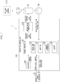
- Fig. 1 is a diagram showing a configuration example of the electric operator for a tap changer of the embodiment.
- the electric operator for a tap changer 1 may include, for example, an upper level panel operator 10, a motor 20, a multi-rotation type encoder 30, and an operation controller 100.
- a combination of the motor 20 and a motor drive controller 130 is an example of a "driver.”
- the upper level panel operator 10 outputs a control signal according to an operation by an operator or the like on an operator provided in an upper level device to the operation controller 100.
- the control signal from the upper level panel operator 10 may include, for example, an upper level control signal.
- the "upper level control" is tap changing control associated with, for example, step-up control or step-down control with respect to an on-load tap changer LTC.
- the motor 20 changes positions of taps (connection points along windings in which a constant number of rotations can be selected) of the on-load tap changer LTC by rotating a rotatable shaft part (for example, a main drive shaft 21 to be described below) in a predetermined direction.
- the motor 20 rotates the main drive shaft in opposite directions according to, for example, step-up control and step-down control.
- the electric operator for a tap changer 1 changes a turn ratio of a transformer in which the on-load tap changer LTC is installed and adjusts a voltage of the transformer by changing a tap position of the on-load tap changer LTC using the motor 20. Details of a component configuration of the motor 20 of the embodiment will be described below.
- the multi-rotation type encoder 30 may be mounted, for example, just below the main drive shaft that rotates due to driving of the motor 20.
- the multi-rotation type encoder 30 includes a member that rotates n (n> 0) times with respect to one rotation of the main drive shaft and detects a rotation position of the main drive shaft by detecting a rotation position of the member. Also, the multi-rotation type encoder 30 outputs detected rotation position information to the operation controller 100.
- the "rotation position information" is absolute position information (an absolute value) including, for example, a rotation angle and the number of rotations in multiple rotations of the main drive shaft.
- the multi-rotation type encoder 30 outputs the rotation position information when the rotation position of the main drive shaft has changed (when the rotation angle has deviated by several [degrees]).
- the operation controller 100 may include, for example, an operator 110, a change controller 120, and the motor drive controller 130.
- the change controller 120 and the motor drive controller 130 are each realized by a hardware processor such as a central processing unit (CPU) executing a program (software). Also, some or all of these components may be realized by hardware (a circuit unit; including circuitry) such as a large scale integration (LSI) or an application specific integrated circuit (ASIC), a field-programmable gate array (FPGA), or a graphics processing unit (GPU), or may be realized by software and hardware in cooperation.
- LSI large scale integration
- ASIC application specific integrated circuit
- FPGA field-programmable gate array
- GPU graphics processing unit
- the program may be stored in a storage device (not shown) of the operation controller 100 in advance, or may be stored in a detachable storage medium such as a DVD or a CD-ROM and then installed in a hard disk drive (HDD) or flash memory of the operation controller 100 when the storage medium is mounted on a drive device.
- a storage device not shown
- a detachable storage medium such as a DVD or a CD-ROM
- HDD hard disk drive
- flash memory of the operation controller 100 when the storage medium is mounted on a drive device.
- the operator 110 outputs operation content by a manual operation of a user to the change controller 120.
- the "operation content by a manual operation” may be, for example, a signal for controlling a step-up operation or a step-down operation which can be obtained by the user manually operating an operation button that gives an instruction to step up or step down a voltage using a transformer, mounted as the operator 110 in advance.
- the change controller 120 may include, for example, an operation receiver 122, a monitor 124, a command controller 126, and an output 128.
- the command controller is an example of a "controller.”
- the operation receiver 122 receives a control signal instructing tap changing by step-up or step-down of the on-load tap changer LTC from the operator 110 or the upper level panel operator 10.
- the monitor 124 monitors a state of the on-load tap changer LTC on the basis of the rotation position information detected by the multi-rotation type encoder 30. Specifically, the monitor 124 monitors a state of the on-load tap changer LTC on the basis of a position and a state of the motor 20 acquired on the basis of the rotation position information.
- the position of the motor 20 may include, for example, a rotation angle and the number of rotations of the main drive shaft rotated by the motor 20. Also, the monitor 124 derives a tap position of the on-load tap changer LTC on the basis of the rotation angle and the number of rotations.
- the monitor 124 monitors a state of the on-load tap changer LTC (a normal state or an abnormal state) on the basis of a state of the motor 20 itself (for example, a state of whether the motor 20 is driven according to a command from the command controller 126).
- a state of the on-load tap changer LTC may be, for example, a congestion state or a runaway state.
- the "congestion state” may be, for example, a state in which the motor 20 does not rotate within a predetermined time after a rotation control command is output, or a state in which a time from an operation of the motor 20 to a change of the tap exceeds a predetermined time.
- the "runaway state” may be, for example, a state in which the motor 20 continues to drive even though the tap changing by the on-load tap changer LTC has ended and a stop control command has been output to the motor 20.
- the monitor 124 stores and manages the rotation position information obtained from the multi-rotation type encoder 30 in a predetermined register with a counter value such as a binary counter.
- the command controller 126 outputs a command signal of rotation control or stop control with respect to the motor 20 to the motor drive controller 130 on the basis of control information received by the operation receiver 122.
- the output 128 outputs a state of control by the operation controller 100 (for example, a monitoring result from the monitor 124) or the like.
- the output 128 outputs a control signal such as an operating signal to the upper level panel operator 10 at a predetermined timing as a notification signal for the upper level.
- the "operating signal” may be, for example, a signal represented as 1 when the motor 20 is operating and 0 when the motor 20 is stopped.
- the output 128 may include, for example, a light emitter (for example, a light emitting diode (LED)) for notifying of a processing state or a display device for displaying an image. For example, when an error or an abnormality occurs in the tap changing control, the output 128 turns on an LED for abnormality detection or causes the display device to display that an abnormality has occurred.
- a light emitter for example, a light emitting diode (LED)
- the motor drive controller 130 When the motor drive controller 130 receives a rotation control signal from the change controller 120, the motor drive controller 130 rotates the motor 20 in a predetermined direction and executes the tap changing by step control. Also, when the motor drive controller 130 receives a stop control signal from the change controller 120, the motor drive controller 130 executes drive control to stop the rotation of the motor 20.
- Fig. 2 is a view illustrating an example of a component configuration of the motor 20 of the embodiment.
- the motor 20 illustrated in Fig. 2 may include, for example, the main drive shaft 21, a motor-side pulley 22, a main drive shaft-side pulley 23, a tension pulley 24, a timing belt 25, a bevel gear 26, a handle shaft 27, and a handle interlock 28.
- the multi-rotation type encoder 30 is also illustrated.
- the motor-side pulley 22 is attached to a rotating shaft of the motor 20 and is coupled to the main drive shaft-side pulley 23 via the timing belt 25.
- the main drive shaft 21 is attached to the main drive shaft-side pulley 23, and the multi-rotation type encoder 30 is directly attached just below the main drive shaft 21 without a speed reduction mechanism or the like interposed therebetween.
- the multi-rotation type encoder 30 is attached to the main drive shaft 21 as in the configuration of Fig. 2 , rotation position information of the main drive shaft 21 can be detected more accurately.
- the tension pulley 24 improves an interlocking property between the motor 20 and the main drive shaft 21 by applying tension to the timing belt 25.
- the main drive shaft 21 is connected to the handle shaft 27 by the bevel gear 26.
- the handle interlock 28 is attached to the handle shaft 27.
- the handle interlock 28 performs restriction so that an electric operation is not performed, for example, when a worker changes a tap manually using the handle at the time of maintenance or the like.
- Fig. 3 is a diagram showing a configuration of the electric operator for a tap changer shown in Fig. 1 from a viewpoint of hardware.
- the electric operator for a tap changer 1 includes the motor 20, the multi-rotation type encoder 30, a power receiver 200, a no fuse breaker (NFB) 210, a motor switch 220, a power converter 230, an in-panel operation switch 240, a trip relay 250, a control board 260, a display device 270, and an upper level board 280.
- the in-panel operation switch 240 corresponds to the operator 110
- the upper level board 280 corresponds to the upper level panel operator 10.
- the control board 260 corresponds to the operation controller 100.
- Power for example, three-phase AC 210 [V] supplied to the motor 20 passes through the power receiver 200, is output to the motor switch 220 via the NFB 210 serving as a wiring breaker, and then is supplied to the motor 20.
- NFB 210 serving as a wiring breaker
- the in-panel operation switch 240 also includes a step-up switch that causes the control board 260 to execute processing based on step-up control, a step-down switch that causes the control board 260 to execute step-down control, and an execution switch that causes the control board 260 to execute stop control. Also, the in-panel operation switch 240 may include a remote switch that remotely controls the step-up, the step-down, or the stop.
- control signals from the in-panel operation switch 240 and the upper level board 280 are input to the control board 260.
- the control board 260 executes control of rotating the motor 20 in a step-up direction or a step-down direction, braking to stop the rotation, or the like by using the input control signal as a trigger to operate the motor switch 220.
- the trip relay 250 is a circuit that receives a command from the control board 260 and trips the NFB 210 (power cut-off) when the control board 260 detects a runaway state. Also, the trip relay 250 trips the NFB 210 when the stop switch is pressed by the in-panel operation switch 240. Due to power cut-off control by the trip relay 250, for example, damage to the transformer due to a runaway state can be avoided.
- the power converter 230 converts the power supplied from the power receiver 200 via the NFB 210 into a DC voltage of 24 [V] used by the control board 260.
- a control current to the motor switch 220 can be made very small. Also, reduction in size and capacity of the motor switch 220 can be realized.
- the power converter 230 outputs a command to the trip relay 250 via the control board 260 before the power supply is completely lost.
- the trip relay 250 trips the NFB 210 on the basis of the command to cut off power supply to the motor.
- the control board 260 may include, for example, an FPGA 262.
- the FPGA 262 executes, for example, functions in each configuration of the change controller 120 described above.
- the control board 260 performs counter control related to tap changing using the binary counter in which the rotation position information detected by the multi-rotation type encoder 30 is stored in the registers.
- the control board 260 parameterizes setting information including at least one of a tap changing position, a stop position, and a tap limit value (for example, a tap upper limit position during step-up and a tap lower limit position during step-down), and an intermediate tap position of the on-load tap changer LTC, and stores it in the registers or the like.
- the control board 260 monitors a state of the on-load tap changer LTC on the basis of the stored parameters.
- the control board 260 performs display control on the display device 270 on the basis of the monitoring result or the like.
- the display device 270 may be, for example, a liquid crystal display (LCD), an organic electro luminescence (EL) display device, or the like. Also, the display device 270 displays information input/output by the control board 260, a monitoring result, an abnormal state, or the like in a predetermined display mode.
- LCD liquid crystal display
- EL organic electro luminescence
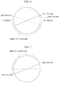
- Fig. 4 is a diagram for explaining tap changing control at the time of step-up.
- Fig. 4 shows a relationship between the tap changing at the time of step-up and the number of rotations of the main drive shaft 21 obtained from the multi-rotation type encoder 30.
- the tap changing of the on-load tap changer LTC is performed by one tap when the main drive shaft 21 is rotated 33 times.
- the example of Fig. 4 shows a schematic diagram in which a normal start position in the tap changing at the time of step-up is set to 0 [degrees] and a normal end position after ending the changing is set to 180 [degrees].
- the operation controller 100 performs control of rotating the main drive shaft 21 in a first direction from an initial value (normal start position 0 [degrees]) at the time of the tap changing at the time of step-up, and performs control of stopping the rotation at a normal stop position 180 [degrees] after 33 rotations.
- an overstroke of an amount of two rotations occurs from the normal stop position between output of a control signal for stopping the motor 20 by the operation controller 100 and actual stop of the motor 20, and thus an actual stop position is a position ahead of the normal stop position by the amount of two rotations.
- Fig. 5 is a diagram for explaining the tap changing control when step-up control is additionally performed after step-up control.
- Fig. 5 shows a relationship between tap changing and the number of rotations of the main drive shaft 21 obtained from the multi-rotation type encoder 30 when step-up control is additionally performed after the step-up control according to Fig. 4 .
- the operation controller 100 performs the tap changing by rotating the main drive shaft 21 33 times using the motor 20 with the stop position of the previous time as a reference.
- Fig. 6 is a diagram for explaining the tap changing control when step-down control is performed after step-up control. Further, in the example of Fig. 6 , it is assumed that step-down control is performed after the step-up control shown in FIG. 5 is executed.
- step-up control is switched to step-down control
- a rotation direction of the main drive shaft 21 becomes an opposite direction (second direction) to the first direction. Therefore, unless rotation control is performed with an amount of the overstroke taken into account, there is a possibility that a timing of the stop may be shifted and the tap changing control may not be performed correctly. Therefore, when the control is switched from the step-up to the step-down, the operation controller 100 rotates the main drive shaft 21 until reaching the number of rotations at which the number of rotations due to the overstroke is added to the 33 rotations required for tap changing.
- the operation controller 100 adds an amount of four rotations, which is a sum of two rotations for cancelling the overstroke amount in the previous step-up control and two rotations of the overstroke due to the step-down control, to the 33 rotations required for tap changing, and executes control for 37 rotations in total. Further, although the above-described processing has shown a case of switching from step-up to step-down, control for 37 rotations is similarly executed also when step-down is switched to step-up.
- Fig. 7 is a diagram for explaining the tap changing control when step-down control is additionally performed after step-down control.
- the example of Fig. 7 shows a relationship between tap changing and the number of rotations of the main drive shaft 21 obtained from the multi-rotation type encoder 30 when step-down control is additionally performed after the step-down control according to Fig. 6 .
- the operation controller 100 performs the tap changing by rotating the main drive shaft 21 33 times using the motor 20 with the stop position of the previous time as a reference. In this case as well, an overstroke of an amount of two rotations occurs.
- the operation controller 100 when rotation control is performed in the same direction as that in the previous rotation control such as step-up to step-up or step-down to step-down, the operation controller 100 performs the rotation control for an amount of 33 rotations, and when rotation control is performed in the opposite direction to that in the previous rotation control such as step-up to step-down or step-down to step-up, the operation controller 100 performs the control for an amount of 37 rotations. Thereby, the operation controller 100 can realize appropriate tap changing control.
- the operation controller 100 may store the tap changing and the information on the number of rotations at the time of step-up and step-down in association with each other as a tap changing control table, and may execute the rotation control at the time of step-up and step-down on the basis of the tap changing control table.
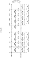
- Fig. 8 is a diagram for explaining a state of the tap changing control at the time of step-up and step-down using the tap changing control table.
- T1, T2,..., TN indicate identification information for identifying the changed taps and the number of rotations related to the tap changing at the time of step-up and step-down.
- the example of Fig. 8 shows that control for 33 rotations is performed when the tap is changed from step-up to step-up or step-down to step-down, and rotation control for 37 rotations including four rotations of the overstroke is executed at the timing of changing the operation direction from step-up to step-down or step-down to step-up.
- electronic control by the operation controller 100 can be realized without performing the control for the overstroke with a mechanical configuration.
- control such as ending the processing by acquiring the abnormal state (congestion) when the stop position is less than the normal stop position and the abnormal state (runaway) that exceeds the normal stop position can be performed. Further, the congestion state can be ascertained from the control time and the stop position, and the runaway state can be ascertained from the number of rotations obtained from the multi-rotation type encoder 30.
- FIG. 9 is a flowchart showing an example of processing of the electric operator for a tap changer of the embodiment.
- an encoder signal from the multi-rotation type encoder 30 is input to the monitor 124 (step S100).
- An output signal of the multi-rotation type encoder 30 is output as an electric signal such as a 16-bit (bit) gray code. Therefore, the monitor 124 converts the input gray code into an electronic signal such as a binary coded decimal (BCD) code that can be recognized by the operation controller 100 (step S102).
- BCD binary coded decimal
- the monitor 124 breaks down the converted electric signal into a rotation angle signal for a single rotation and a signal for a multi-rotation count and stores them in registers. Specifically, the monitor 124 acquires the rotation angle and stores it in a 5-bit register (register A) (step S104), and acquires the number of rotations and the tap position and stores them in an 11-bit register (register B) (step S106).
- the number of rotations can be stored up to, for example, a maximum amount of 2048 rotations, but the present invention is not limited thereto.
- the operation receiver 122 receives a step-up command or a step-down command with respect to the on-load tap changer LTC from the operator 110 or the upper level panel operator 10 (step S108).
- the command controller 126 outputs a rotation control command for driving the motor 20 to the motor drive controller 130 on the basis of content of the command and thereby drives the motor (step S 110).
- the monitor 124 detects a change in rotation position information due to driving of the motor 20 from the multi-rotation type encoder 30 (step S112).
- the monitor 124 monitors a time (first time) from the output of the rotation command to an operation of the multi-rotation type encoder 30 (step S114).
- the monitor 124 monitors a time (second time) from the operation of the multi-rotation type encoder 30 to a change of the tap (step S116).
- the monitor 124 determines whether or not the first time or the second time has timed out (step S118). The determination of timing out is made such that it has timed out when, for example, the first time exceeds a first threshold value Th1 or when the second time exceeds a second threshold value Th2.
- the monitor 124 monitors a change in the binary counter at the time of step-up or step-down (step S120), and determines whether or not the control is normal on the basis of the changed value of the binary counter (step S122). For example, in the processing of steps S120 and S122, the monitor 124 monitors whether or not a rotation direction of the motor 20 at the time of the step-up control matches a rotation direction of the motor 20 at the time of the step-down control. When the control is not normal, the output 128 outputs error information indicating that the control is not normal (step S124). When the control is determined to be normal, the monitor 124 executes stop control processing (step S200).
- step S118 when the first time or the second time is determined to have timed out, it is judged that there is congestion and abnormality processing is executed (step S300). Thereby, the processing of the present flowchart ends.
- Fig. 10 is a flowchart showing an example of the stop control processing of the embodiment.
- the monitor 124 acquires information on a position to which a brake should be applied to the motor 20 by the stop control (step S202).
- the position to which the brake should be applied may be, for example, a position set according to an Xth rotation and an angle Y [degrees] among the actual number of rotations (for example, 33 rotations).
- the monitor 124 determines whether or not it is a timing (hereinafter referred to as a brake timing) at which the brake should be applied to the motor 20 on the basis of the information on the position to which the brake should be applied (step S204). When it is not the brake timing, the monitor 124 calculates a position at which to stop next time (step S206). In the processing of step S206, a position register for a position at which to stop next time is calculated on the basis of values of the register A and the register B.
- +33 is added to the current position register that is associated with the number of rotations
- +37 is added to the current position register.
- -33 is added to the current position register
- -37 is added to the current position register.
- the monitor 124 determines whether or not the motor 20 has stopped (step S208). When the motor has stopped, the output 128 notifies the outside or the like that the motor has stopped (step S210) and ends movement for one tap (step S212). Also, when it is determined to be the brake timing in the processing of step S204, the command controller 126 outputs a stop control command to the motor drive controller 130 (step S216). Next, the monitor 124 starts a stop timer (step S218).
- step S220 the monitor 124 checks the stop timer (step S220).
- step S222 the stop timer determines whether or not the stop has timed out.
- the determination of timing out by the stop timer is made such that it has timed out when, for example, a count value (third time) of the stop timer exceeds a third threshold value Th3.
- step S400 the monitor 124 judges that there is runaway and performs abnormality processing (step S400).
- step S400 abnormality processing
- Fig. 11 is a flowchart showing an example of the abnormality processing at the time of congestion in the embodiment.
- the command controller 126 outputs a stop control command to the motor drive controller 130 (step S302).
- the output 128 performs an abnormality display that indicates the congestion state (step S304).
- the "abnormality display" in the processing of step S304 may be, for example, a display such as turning on an LED for abnormality detection of congestion, or a display indicating a congestion state on the display device 270.
- Fig. 12 is a flowchart showing an example of the abnormality processing at the time of a runaway in the embodiment.
- the monitor 124 performs a forced trip in the NFB 210 (step S402).
- the output 128 performs an abnormality display that indicates the runaway state (step S404).
- the "abnormality display" in the processing of step S404 may be, for example, a display such as turning on an LED for abnormality detection of a runaway, or a display indicating a runaway state on the display device 270.
- the electric operator for a tap changer 1 includes the motor drive controller 130 that performs tap changing of the tap changer LTC by driving the main drive shaft 21 using the motor 20, a multi-rotation type encoder 30 having a member that rotates n times with respect to one rotation of the main drive shaft 21 and detecting a rotation position of the main drive shaft 21 by detecting a rotation position of the member, the monitor 124 that monitors a state of the tap changer LTC on the basis of the rotation position detected by the multi-rotation type encoder 30, and the change controller 120 that controls the motor drive controller 130 on the basis of a monitoring result from the monitor 124, and thereby adjustment at the time of assembling the electric operator can be simplified and easy maintenance can be realized.
- a mechanical configuration such as a step control mechanism or a dial switch of conventional electric operators is replaced by the electronic control using the multi-rotation type encoder 30 that can acquire multi-rotation absolute position information and the operation controller 100, and thereby the number of mechanical components can be reduced and space saving can be realized.
- the multi-rotation type encoder 30 is directly attached just below the main drive shaft 21 without a speed reduction mechanism interposed therebetween, and the output absolute position information is taken into the operation controller 100, and thereby an accurate number of rotations of the main drive shaft (corresponding to a tap position and the number of rotations of the main drive shaft) and a rotation angle can be ascertained more accurately.
- the present embodiment it is possible to detect an accurate stop accuracy due to increased resolution, and an abnormality state such as a tap congestion that causes a half-way stop or becoming unresponsive due to stuck of the main drive shaft or the like, or a runaway that causes an operation beyond the normal control position.
- the rotation position information can be detected with high accuracy by the multi-rotation type encoder 30, and as a result, a motor stop accuracy can be improved.
- a load of the motor 20 can be reduced and the durability can be improved by performing detection of a position using the multi-rotation type encoder 30 in a non-contact manner without interposing a dial switch.
- the operation controller 100 may statistically learn the tap changing operation and perform automatic adjustment of brake timing and calculation of a tap changing speed at the time of tap changing. As a result, the operation controller 100 can ascertain a problem in the motor 20, a state of a problem in the on-load tap changer LTC main body, or the like.
Landscapes
- Control Of Electric Motors In General (AREA)
- Mechanisms For Operating Contacts (AREA)
Abstract
Description
- An embodiment of the present invention relates to an electric operator for a tap changer and a tap changing method.
- Conventionally, an electric operator for changing a tap position of an on-load tap changer installed in a transformer is known. The electric operator changes a tap position by rotating a main drive shaft connected to a gear using a motor driver serving as a source of power. Operation control of the motor driver is executed by a step control mechanism constituted by a relay sequence circuit using a motor switch that performs an opening and closing operation of the circuit according to an ON/OFF signal of a cam switch connected to the main drive shaft by a gear. Also, the electric operator includes a dial switch connected to the main drive shaft by a gear. The dial switch outputs a tap position signal on the basis of a rotation position of the main drive shaft.
- However, since the conventional electric operator includes a mechanical configuration such as a step control mechanism and a dial switch as described above from a structural perspective, there have been cases in which the number of components was many and assembly and maintenance took time. Also, at the time of assembly or maintenance, the work needs to be done by a person who is familiar with a structure of the mechanism, and thus there have been cases in which a repair and maintenance could not be easily performed due to lack of workability at the time of the maintenance. Also, conventionally, position information of a tap has been able to be acquired with a dial switch, but this signal is for finding a limit (limit value) of a tap and has not been effectively used in operation control of the electric operator.
-
- [Patent Literature 1] Japanese Unexamined Patent Application Publication, First Publication No.
S54-129367 - [Patent Literature 2] Published Japanese Translation No.
2010-502170 - A problem to be solved by the present invention is to provide an electric operator for a tap changer and a tap changing method in which adjustment at the time of assembling the electric operator can be simplified and easy maintenance can be realized.
- An electric operator for a tap changer of the embodiment includes a driver, a multi-rotation type encoder, a monitor, and a controller. The driver performs tap changing of the tap changer by driving a main drive shaft using a motor. The multi-rotation type encoder has a member which rotates n times with respect to one rotation of the main drive shaft and detects a rotation position of the main drive shaft by detecting a rotation position of the member. The monitor monitors a state of the tap changer on the basis of the rotation position detected by the multi-rotation type encoder. The controller controls the driver on the basis of a monitoring result from the monitor.
-
-
Fig. 1 is a diagram showing a configuration example of an electric operator for a tap changer of an embodiment. -
Fig. 2 is a view illustrating an example of a component configuration of amotor 20 of the embodiment. -
Fig. 3 is a diagram showing a configuration of the electric operator for a tap changer shown inFig. 1 from a viewpoint of hardware. -
Fig. 4 is a diagram for explaining tap changing control at the time of step-up. -
Fig. 5 is a diagram for explaining the tap changing control when step-up control is additionally performed after step-up control. -
Fig. 6 is a diagram for explaining the tap changing control when step-down control is performed after step-up control. -
Fig. 7 is a diagram for explaining the tap changing control when step-down control is additionally performed after step-down control. -
Fig. 8 is a diagram for explaining a state of the tap changing control at the time of step-up and step-down using a tap changing control table. -
Fig. 9 is a flowchart showing an example of processing of the electric operator for a tap changer of the embodiment. -
Fig. 10 is a flowchart showing an example of stop control processing of the embodiment. -
Fig. 11 is a flowchart showing an example of abnormality processing at the time of congestion in the embodiment. -
Fig. 12 is a flowchart showing an example of abnormality processing at the time of a runaway in the embodiment. - Hereinafter, an electric operator for a tap changer and a tap changing method of an embodiment will be described with reference to the drawings. In the following embodiment, an on-load tap changer is used as an example of the tap changer.
-
Fig. 1 is a diagram showing a configuration example of the electric operator for a tap changer of the embodiment. The electric operator for atap changer 1 may include, for example, an upperlevel panel operator 10, amotor 20, amulti-rotation type encoder 30, and anoperation controller 100. A combination of themotor 20 and amotor drive controller 130 is an example of a "driver." - The upper
level panel operator 10 outputs a control signal according to an operation by an operator or the like on an operator provided in an upper level device to theoperation controller 100. The control signal from the upperlevel panel operator 10 may include, for example, an upper level control signal. The "upper level control" is tap changing control associated with, for example, step-up control or step-down control with respect to an on-load tap changer LTC. - The
motor 20 changes positions of taps (connection points along windings in which a constant number of rotations can be selected) of the on-load tap changer LTC by rotating a rotatable shaft part (for example, amain drive shaft 21 to be described below) in a predetermined direction. Themotor 20 rotates the main drive shaft in opposite directions according to, for example, step-up control and step-down control. The electric operator for atap changer 1 changes a turn ratio of a transformer in which the on-load tap changer LTC is installed and adjusts a voltage of the transformer by changing a tap position of the on-load tap changer LTC using themotor 20. Details of a component configuration of themotor 20 of the embodiment will be described below. - The
multi-rotation type encoder 30 may be mounted, for example, just below the main drive shaft that rotates due to driving of themotor 20. Themulti-rotation type encoder 30 includes a member that rotates n (n> 0) times with respect to one rotation of the main drive shaft and detects a rotation position of the main drive shaft by detecting a rotation position of the member. Also, themulti-rotation type encoder 30 outputs detected rotation position information to theoperation controller 100. The "rotation position information" is absolute position information (an absolute value) including, for example, a rotation angle and the number of rotations in multiple rotations of the main drive shaft. Themulti-rotation type encoder 30 outputs the rotation position information when the rotation position of the main drive shaft has changed (when the rotation angle has deviated by several [degrees]). - The
operation controller 100 may include, for example, anoperator 110, achange controller 120, and themotor drive controller 130. Thechange controller 120 and themotor drive controller 130 are each realized by a hardware processor such as a central processing unit (CPU) executing a program (software). Also, some or all of these components may be realized by hardware (a circuit unit; including circuitry) such as a large scale integration (LSI) or an application specific integrated circuit (ASIC), a field-programmable gate array (FPGA), or a graphics processing unit (GPU), or may be realized by software and hardware in cooperation. The program may be stored in a storage device (not shown) of theoperation controller 100 in advance, or may be stored in a detachable storage medium such as a DVD or a CD-ROM and then installed in a hard disk drive (HDD) or flash memory of theoperation controller 100 when the storage medium is mounted on a drive device. - The
operator 110 outputs operation content by a manual operation of a user to thechange controller 120. The "operation content by a manual operation" may be, for example, a signal for controlling a step-up operation or a step-down operation which can be obtained by the user manually operating an operation button that gives an instruction to step up or step down a voltage using a transformer, mounted as theoperator 110 in advance. - The
change controller 120 may include, for example, anoperation receiver 122, amonitor 124, acommand controller 126, and anoutput 128. The command controller is an example of a "controller." Theoperation receiver 122 receives a control signal instructing tap changing by step-up or step-down of the on-load tap changer LTC from theoperator 110 or the upperlevel panel operator 10. - The
monitor 124 monitors a state of the on-load tap changer LTC on the basis of the rotation position information detected by themulti-rotation type encoder 30. Specifically, themonitor 124 monitors a state of the on-load tap changer LTC on the basis of a position and a state of themotor 20 acquired on the basis of the rotation position information. The position of themotor 20 may include, for example, a rotation angle and the number of rotations of the main drive shaft rotated by themotor 20. Also, themonitor 124 derives a tap position of the on-load tap changer LTC on the basis of the rotation angle and the number of rotations. Also, themonitor 124 monitors a state of the on-load tap changer LTC (a normal state or an abnormal state) on the basis of a state of themotor 20 itself (for example, a state of whether themotor 20 is driven according to a command from the command controller 126). Here, an "abnormal state" of the on-load tap changer LTC may be, for example, a congestion state or a runaway state. The "congestion state" may be, for example, a state in which themotor 20 does not rotate within a predetermined time after a rotation control command is output, or a state in which a time from an operation of themotor 20 to a change of the tap exceeds a predetermined time. The "runaway state" may be, for example, a state in which themotor 20 continues to drive even though the tap changing by the on-load tap changer LTC has ended and a stop control command has been output to themotor 20. Themonitor 124 stores and manages the rotation position information obtained from themulti-rotation type encoder 30 in a predetermined register with a counter value such as a binary counter. - The
command controller 126 outputs a command signal of rotation control or stop control with respect to themotor 20 to themotor drive controller 130 on the basis of control information received by theoperation receiver 122. - The
output 128 outputs a state of control by the operation controller 100 (for example, a monitoring result from the monitor 124) or the like. For example, theoutput 128 outputs a control signal such as an operating signal to the upperlevel panel operator 10 at a predetermined timing as a notification signal for the upper level. The "operating signal" may be, for example, a signal represented as 1 when themotor 20 is operating and 0 when themotor 20 is stopped. Also, theoutput 128 may include, for example, a light emitter (for example, a light emitting diode (LED)) for notifying of a processing state or a display device for displaying an image. For example, when an error or an abnormality occurs in the tap changing control, theoutput 128 turns on an LED for abnormality detection or causes the display device to display that an abnormality has occurred. - When the
motor drive controller 130 receives a rotation control signal from thechange controller 120, themotor drive controller 130 rotates themotor 20 in a predetermined direction and executes the tap changing by step control. Also, when themotor drive controller 130 receives a stop control signal from thechange controller 120, themotor drive controller 130 executes drive control to stop the rotation of themotor 20. - Next, a component configuration of the
motor 20 of the embodiment will be described.Fig. 2 is a view illustrating an example of a component configuration of themotor 20 of the embodiment. Themotor 20 illustrated inFig. 2 may include, for example, themain drive shaft 21, a motor-side pulley 22, a main drive shaft-side pulley 23, atension pulley 24, atiming belt 25, abevel gear 26, ahandle shaft 27, and ahandle interlock 28. Also, in the example ofFig. 2 , themulti-rotation type encoder 30 is also illustrated. - The motor-
side pulley 22 is attached to a rotating shaft of themotor 20 and is coupled to the main drive shaft-side pulley 23 via thetiming belt 25. Themain drive shaft 21 is attached to the main drive shaft-side pulley 23, and themulti-rotation type encoder 30 is directly attached just below themain drive shaft 21 without a speed reduction mechanism or the like interposed therebetween. When themulti-rotation type encoder 30 is attached to themain drive shaft 21 as in the configuration ofFig. 2 , rotation position information of themain drive shaft 21 can be detected more accurately. - Also, the
tension pulley 24 improves an interlocking property between themotor 20 and themain drive shaft 21 by applying tension to thetiming belt 25. Themain drive shaft 21 is connected to thehandle shaft 27 by thebevel gear 26. Thehandle interlock 28 is attached to thehandle shaft 27. Thehandle interlock 28 performs restriction so that an electric operation is not performed, for example, when a worker changes a tap manually using the handle at the time of maintenance or the like. -
Fig. 3 is a diagram showing a configuration of the electric operator for a tap changer shown inFig. 1 from a viewpoint of hardware. In the example ofFig. 3 , the electric operator for atap changer 1 includes themotor 20, themulti-rotation type encoder 30, apower receiver 200, a no fuse breaker (NFB) 210, amotor switch 220, apower converter 230, an in-panel operation switch 240, atrip relay 250, acontrol board 260, adisplay device 270, and anupper level board 280. Here, the in-panel operation switch 240 corresponds to theoperator 110, and theupper level board 280 corresponds to the upperlevel panel operator 10. Also, thecontrol board 260 corresponds to theoperation controller 100. - Power (for example, three-phase AC 210 [V]) supplied to the
motor 20 passes through thepower receiver 200, is output to themotor switch 220 via theNFB 210 serving as a wiring breaker, and then is supplied to themotor 20. - The in-
panel operation switch 240 also includes a step-up switch that causes thecontrol board 260 to execute processing based on step-up control, a step-down switch that causes thecontrol board 260 to execute step-down control, and an execution switch that causes thecontrol board 260 to execute stop control. Also, the in-panel operation switch 240 may include a remote switch that remotely controls the step-up, the step-down, or the stop. - Also, control signals from the in-
panel operation switch 240 and the upper level board 280 (for example, step-up control or step-down control) are input to thecontrol board 260. Thecontrol board 260 executes control of rotating themotor 20 in a step-up direction or a step-down direction, braking to stop the rotation, or the like by using the input control signal as a trigger to operate themotor switch 220. - The
trip relay 250 is a circuit that receives a command from thecontrol board 260 and trips the NFB 210 (power cut-off) when thecontrol board 260 detects a runaway state. Also, thetrip relay 250 trips theNFB 210 when the stop switch is pressed by the in-panel operation switch 240. Due to power cut-off control by thetrip relay 250, for example, damage to the transformer due to a runaway state can be avoided. - The
power converter 230 converts the power supplied from thepower receiver 200 via theNFB 210 into a DC voltage of 24 [V] used by thecontrol board 260. In the electric operator for atap changer 1 according to the embodiment, since themotor 20 is controlled by electronic control based on information detected by themulti-rotation type encoder 30 without having a mechanical configuration such as a step control mechanism or a dial switch, a control current to themotor switch 220 can be made very small. Also, reduction in size and capacity of themotor switch 220 can be realized. - Also, since control on the
control board 260 cannot be performed when power supply is cut off due to a power failure or the like, thepower converter 230 outputs a command to thetrip relay 250 via thecontrol board 260 before the power supply is completely lost. Thereby, thetrip relay 250 trips theNFB 210 on the basis of the command to cut off power supply to the motor. - The
control board 260 may include, for example, anFPGA 262. TheFPGA 262 executes, for example, functions in each configuration of thechange controller 120 described above. Also, thecontrol board 260 performs counter control related to tap changing using the binary counter in which the rotation position information detected by themulti-rotation type encoder 30 is stored in the registers. For example, on the basis of the binary counter, thecontrol board 260 parameterizes setting information including at least one of a tap changing position, a stop position, and a tap limit value (for example, a tap upper limit position during step-up and a tap lower limit position during step-down), and an intermediate tap position of the on-load tap changer LTC, and stores it in the registers or the like. Also, thecontrol board 260 monitors a state of the on-load tap changer LTC on the basis of the stored parameters. Also, thecontrol board 260 performs display control on thedisplay device 270 on the basis of the monitoring result or the like. - The
display device 270 may be, for example, a liquid crystal display (LCD), an organic electro luminescence (EL) display device, or the like. Also, thedisplay device 270 displays information input/output by thecontrol board 260, a monitoring result, an abnormal state, or the like in a predetermined display mode. - Next, tap changing control of the embodiment will be described.
Fig. 4 is a diagram for explaining tap changing control at the time of step-up.Fig. 4 shows a relationship between the tap changing at the time of step-up and the number of rotations of themain drive shaft 21 obtained from themulti-rotation type encoder 30. In the following description, it is assumed that the tap changing of the on-load tap changer LTC is performed by one tap when themain drive shaft 21 is rotated 33 times. Also, the example ofFig. 4 shows a schematic diagram in which a normal start position in the tap changing at the time of step-up is set to 0 [degrees] and a normal end position after ending the changing is set to 180 [degrees]. - The
operation controller 100 performs control of rotating themain drive shaft 21 in a first direction from an initial value (normal start position 0 [degrees]) at the time of the tap changing at the time of step-up, and performs control of stopping the rotation at a normal stop position 180 [degrees] after 33 rotations. However, in practice, an overstroke of an amount of two rotations occurs from the normal stop position between output of a control signal for stopping themotor 20 by theoperation controller 100 and actual stop of themotor 20, and thus an actual stop position is a position ahead of the normal stop position by the amount of two rotations. -
Fig. 5 is a diagram for explaining the tap changing control when step-up control is additionally performed after step-up control.Fig. 5 shows a relationship between tap changing and the number of rotations of themain drive shaft 21 obtained from themulti-rotation type encoder 30 when step-up control is additionally performed after the step-up control according toFig. 4 . For example, when step-up control is additionally performed after step-up control, since themain drive shaft 21 is rotated in the same direction (the first direction) as that in the previous time, theoperation controller 100 performs the tap changing by rotating themain drive shaft 21 33 times using themotor 20 with the stop position of the previous time as a reference. -
Fig. 6 is a diagram for explaining the tap changing control when step-down control is performed after step-up control. Further, in the example ofFig. 6 , it is assumed that step-down control is performed after the step-up control shown inFIG. 5 is executed. When step-up control is switched to step-down control, a rotation direction of themain drive shaft 21 becomes an opposite direction (second direction) to the first direction. Therefore, unless rotation control is performed with an amount of the overstroke taken into account, there is a possibility that a timing of the stop may be shifted and the tap changing control may not be performed correctly. Therefore, when the control is switched from the step-up to the step-down, theoperation controller 100 rotates themain drive shaft 21 until reaching the number of rotations at which the number of rotations due to the overstroke is added to the 33 rotations required for tap changing. - Specifically, as shown in
Fig. 6 , theoperation controller 100 adds an amount of four rotations, which is a sum of two rotations for cancelling the overstroke amount in the previous step-up control and two rotations of the overstroke due to the step-down control, to the 33 rotations required for tap changing, and executes control for 37 rotations in total. Further, although the above-described processing has shown a case of switching from step-up to step-down, control for 37 rotations is similarly executed also when step-down is switched to step-up. -
Fig. 7 is a diagram for explaining the tap changing control when step-down control is additionally performed after step-down control. The example ofFig. 7 shows a relationship between tap changing and the number of rotations of themain drive shaft 21 obtained from themulti-rotation type encoder 30 when step-down control is additionally performed after the step-down control according toFig. 6 . For example, when step-down control is additionally performed after step-down control, since themain drive shaft 21 is rotated in the same direction (the second direction) as that in the previous time, theoperation controller 100 performs the tap changing by rotating themain drive shaft 21 33 times using themotor 20 with the stop position of the previous time as a reference. In this case as well, an overstroke of an amount of two rotations occurs. - In this way, when rotation control is performed in the same direction as that in the previous rotation control such as step-up to step-up or step-down to step-down, the
operation controller 100 performs the rotation control for an amount of 33 rotations, and when rotation control is performed in the opposite direction to that in the previous rotation control such as step-up to step-down or step-down to step-up, theoperation controller 100 performs the control for an amount of 37 rotations. Thereby, theoperation controller 100 can realize appropriate tap changing control. - Further, the
operation controller 100 may store the tap changing and the information on the number of rotations at the time of step-up and step-down in association with each other as a tap changing control table, and may execute the rotation control at the time of step-up and step-down on the basis of the tap changing control table. -
Fig. 8 is a diagram for explaining a state of the tap changing control at the time of step-up and step-down using the tap changing control table. InFig. 8 , T1, T2,..., TN indicate identification information for identifying the changed taps and the number of rotations related to the tap changing at the time of step-up and step-down. The example ofFig. 8 shows that control for 33 rotations is performed when the tap is changed from step-up to step-up or step-down to step-down, and rotation control for 37 rotations including four rotations of the overstroke is executed at the timing of changing the operation direction from step-up to step-down or step-down to step-up. In this way, when the tap position changing control is performed with the number of rotations taken into account on the basis of the rotation direction, electronic control by theoperation controller 100 can be realized without performing the control for the overstroke with a mechanical configuration. - Also, in the embodiment, when the
multi-rotation type encoder 30 is used, since the number of rotations of themain drive shaft 21 due to the actual tap changing matches the number of rotations detected from themulti-rotation type encoder 30, control such as ending the processing by acquiring the abnormal state (congestion) when the stop position is less than the normal stop position and the abnormal state (runaway) that exceeds the normal stop position can be performed. Further, the congestion state can be ascertained from the control time and the stop position, and the runaway state can be ascertained from the number of rotations obtained from themulti-rotation type encoder 30. - Next, processing of the electric operator for a tap changer of the embodiment will be described.
Fig. 9 is a flowchart showing an example of processing of the electric operator for a tap changer of the embodiment. In the processing ofFig. 9 , an encoder signal from themulti-rotation type encoder 30 is input to the monitor 124 (step S100). An output signal of themulti-rotation type encoder 30 is output as an electric signal such as a 16-bit (bit) gray code. Therefore, themonitor 124 converts the input gray code into an electronic signal such as a binary coded decimal (BCD) code that can be recognized by the operation controller 100 (step S102). - Next, the
monitor 124 breaks down the converted electric signal into a rotation angle signal for a single rotation and a signal for a multi-rotation count and stores them in registers. Specifically, themonitor 124 acquires the rotation angle and stores it in a 5-bit register (register A) (step S104), and acquires the number of rotations and the tap position and stores them in an 11-bit register (register B) (step S106). The number of rotations can be stored up to, for example, a maximum amount of 2048 rotations, but the present invention is not limited thereto. - Next, the
operation receiver 122 receives a step-up command or a step-down command with respect to the on-load tap changer LTC from theoperator 110 or the upper level panel operator 10 (step S108). Next, thecommand controller 126 outputs a rotation control command for driving themotor 20 to themotor drive controller 130 on the basis of content of the command and thereby drives the motor (step S 110). Next, themonitor 124 detects a change in rotation position information due to driving of themotor 20 from the multi-rotation type encoder 30 (step S112). - Next, the
monitor 124 monitors a time (first time) from the output of the rotation command to an operation of the multi-rotation type encoder 30 (step S114). Next, themonitor 124 monitors a time (second time) from the operation of themulti-rotation type encoder 30 to a change of the tap (step S116). Next, themonitor 124 determines whether or not the first time or the second time has timed out (step S118). The determination of timing out is made such that it has timed out when, for example, the first time exceeds a first threshold value Th1 or when the second time exceeds a second threshold value Th2. - When the first time or the second time has not timed out, the
monitor 124 monitors a change in the binary counter at the time of step-up or step-down (step S120), and determines whether or not the control is normal on the basis of the changed value of the binary counter (step S122). For example, in the processing of steps S120 and S122, themonitor 124 monitors whether or not a rotation direction of themotor 20 at the time of the step-up control matches a rotation direction of themotor 20 at the time of the step-down control. When the control is not normal, theoutput 128 outputs error information indicating that the control is not normal (step S124). When the control is determined to be normal, themonitor 124 executes stop control processing (step S200). - Also, in the processing of step S118, when the first time or the second time is determined to have timed out, it is judged that there is congestion and abnormality processing is executed (step S300). Thereby, the processing of the present flowchart ends.
- Next, stop control processing in step S200 will be described.
Fig. 10 is a flowchart showing an example of the stop control processing of the embodiment. In the example ofFig. 10 , themonitor 124 acquires information on a position to which a brake should be applied to themotor 20 by the stop control (step S202). The position to which the brake should be applied may be, for example, a position set according to an Xth rotation and an angle Y [degrees] among the actual number of rotations (for example, 33 rotations). This is because, for example, when a stop control signal for stopping themotor 20 at a time point at which the rotation position is at an angle of 0 [degrees] at a 33rd rotation is output, since themotor 20 rotates several more times by inertia, the brake is applied to a position before the actual stop position. As an example of the above-described values of X and Y, for example, X = 31 and Y = 120. Also, the position to which the brake should be applied is acquired by position registers of the register A and the register B described above. - Next, the
monitor 124 determines whether or not it is a timing (hereinafter referred to as a brake timing) at which the brake should be applied to themotor 20 on the basis of the information on the position to which the brake should be applied (step S204). When it is not the brake timing, themonitor 124 calculates a position at which to stop next time (step S206). In the processing of step S206, a position register for a position at which to stop next time is calculated on the basis of values of the register A and the register B. Specifically, when the step-up control is performed at present and the step-up control is also to be performed next time, +33 is added to the current position register that is associated with the number of rotations, and when the step-down is performed at present but the step-up is to be performed next time, +37 is added to the current position register. Also, when the step-down is performed at present and the step-down is also to be performed next time, -33 is added to the current position register, and when the step-up is performed at present but the step-down is to be performed next time, -37 is added to the current position register. - Next, the
monitor 124 determines whether or not themotor 20 has stopped (step S208). When the motor has stopped, theoutput 128 notifies the outside or the like that the motor has stopped (step S210) and ends movement for one tap (step S212). Also, when it is determined to be the brake timing in the processing of step S204, thecommand controller 126 outputs a stop control command to the motor drive controller 130 (step S216). Next, themonitor 124 starts a stop timer (step S218). - After the processing of step S218 has ended, or in the processing of step S208, when the
motor 20 has not stopped, themonitor 124 checks the stop timer (step S220). Next, the stop timer determines whether or not the stop has timed out (step S222). The determination of timing out by the stop timer is made such that it has timed out when, for example, a count value (third time) of the stop timer exceeds a third threshold value Th3. When it has timed out, themonitor 124 judges that there is runaway and performs abnormality processing (step S400). Also, when it has not timed out in the processing of step S222, the processing returns to the processing of step S208. Thereby, the present flowchart ends. - Next, abnormality processing when it is determined that there is congestion will be described using a flowchart.
Fig. 11 is a flowchart showing an example of the abnormality processing at the time of congestion in the embodiment. In the example ofFig. 11 , thecommand controller 126 outputs a stop control command to the motor drive controller 130 (step S302). Next, theoutput 128 performs an abnormality display that indicates the congestion state (step S304). The "abnormality display" in the processing of step S304 may be, for example, a display such as turning on an LED for abnormality detection of congestion, or a display indicating a congestion state on thedisplay device 270. Thereby, the processing of the present flowchart ends. - Next, abnormality processing when it is determined to be in a runaway will be described with reference to a flowchart.
Fig. 12 is a flowchart showing an example of the abnormality processing at the time of a runaway in the embodiment. In the example ofFig. 12 , themonitor 124 performs a forced trip in the NFB 210 (step S402). Next, theoutput 128 performs an abnormality display that indicates the runaway state (step S404). The "abnormality display" in the processing of step S404 may be, for example, a display such as turning on an LED for abnormality detection of a runaway, or a display indicating a runaway state on thedisplay device 270. Thereby, the processing of the present flowchart ends. - According to at least one embodiment described above, the electric operator for a
tap changer 1 includes themotor drive controller 130 that performs tap changing of the tap changer LTC by driving themain drive shaft 21 using themotor 20, amulti-rotation type encoder 30 having a member that rotates n times with respect to one rotation of themain drive shaft 21 and detecting a rotation position of themain drive shaft 21 by detecting a rotation position of the member, themonitor 124 that monitors a state of the tap changer LTC on the basis of the rotation position detected by themulti-rotation type encoder 30, and thechange controller 120 that controls themotor drive controller 130 on the basis of a monitoring result from themonitor 124, and thereby adjustment at the time of assembling the electric operator can be simplified and easy maintenance can be realized. - Specifically, according to at least one embodiment, a mechanical configuration such as a step control mechanism or a dial switch of conventional electric operators is replaced by the electronic control using the
multi-rotation type encoder 30 that can acquire multi-rotation absolute position information and theoperation controller 100, and thereby the number of mechanical components can be reduced and space saving can be realized. Also, themulti-rotation type encoder 30 is directly attached just below themain drive shaft 21 without a speed reduction mechanism interposed therebetween, and the output absolute position information is taken into theoperation controller 100, and thereby an accurate number of rotations of the main drive shaft (corresponding to a tap position and the number of rotations of the main drive shaft) and a rotation angle can be ascertained more accurately. Therefore, according to the present embodiment, it is possible to detect an accurate stop accuracy due to increased resolution, and an abnormality state such as a tap congestion that causes a half-way stop or becoming unresponsive due to stuck of the main drive shaft or the like, or a runaway that causes an operation beyond the normal control position. Also, according to the present embodiment, the rotation position information can be detected with high accuracy by themulti-rotation type encoder 30, and as a result, a motor stop accuracy can be improved. Also, according to the present embodiment, a load of themotor 20 can be reduced and the durability can be improved by performing detection of a position using themulti-rotation type encoder 30 in a non-contact manner without interposing a dial switch. - Further, in the embodiment, for example, the
operation controller 100 may statistically learn the tap changing operation and perform automatic adjustment of brake timing and calculation of a tap changing speed at the time of tap changing. As a result, theoperation controller 100 can ascertain a problem in themotor 20, a state of a problem in the on-load tap changer LTC main body, or the like. - While preferred embodiments of the present invention have been described, it should be understood that these embodiments are exemplary of the invention and are not to be considered as limiting the scope of the invention. The embodiments may be implemented in many other different forms, and various omissions, substitutions, and other modifications can be made without departing from the gist of the invention. The embodiments and modifications thereof should be regarded as being included within the scope and gist of the invention and included in the invention described in the claims and an equivalent scope thereof.
Claims (6)
- An electric operator for a tap changer comprising:a driver which performs tap changing of a tap changer by driving a main drive shaft using a motor;a multi-rotation type encoder including a member which rotates n times with respect to one rotation of the main drive shaft and detecting a rotation position of the main drive shaft by detecting a rotation position of the member;a monitor which monitors a state of the tap changer on the basis of the rotation position detected by the multi-rotation type encoder; anda controller which controls the driver on the basis of a monitoring result from the monitor.
- The electric operator for a tap changer according to claim 1,
wherein the monitor determines whether or not the tap changer is in an abnormal state on the basis of rotation position information and time information of the motor detected by the multi-rotation type encoder. - The electric operator for a tap changer according to claim 2,
wherein the monitor determines that the tap changer is in a congestion state when a first time from an output of a rotation control command for the motor by the controller to a change in the rotation position information detected by the multi-rotation type encoder exceeds a first threshold value, or when a second time from the change in the rotation position information detected by the multi-rotation type encoder to a change of the tap exceeds a second threshold value. - The electric operator for a tap changer according to claim 2 or 3,
wherein the monitor determines that the tap changer is in a runaway state when a third time from an output of stop control for the motor by the controller to a stop of the motor exceeds a third threshold value. - The electric operator for a tap changer according to any one of claims 1 to 4,
wherein the monitor parameterizes setting information including at least one of a tap changing position, a stop position, and a tap limit value, and an intermediate tap position of the tap changer on the basis of the rotation position information detected by the multi-rotation type encoder to perform the monitoring. - A tap changing method, performed by an electric operator for a tap changer, comprising:performing tap changing of a tap changer by driving a main drive shaft using a motor driven by a driver;detecting a rotation position of the main drive shaft by a multi-rotation type encoder including a member that rotates n times with respect to one rotation of the main drive shaft and detecting a rotation position of the member;monitoring a state of the tap changer on the basis of the rotation position detected by the multi-rotation type encoder; andcontrolling the driver on the basis of a monitoring result.
Applications Claiming Priority (1)
| Application Number | Priority Date | Filing Date | Title |
|---|---|---|---|
| PCT/JP2018/023258 WO2019244235A1 (en) | 2018-06-19 | 2018-06-19 | Electric operator for tap changer and tap changing method |
Publications (3)
| Publication Number | Publication Date |
|---|---|
| EP3813086A1 true EP3813086A1 (en) | 2021-04-28 |
| EP3813086A4 EP3813086A4 (en) | 2022-02-09 |
| EP3813086B1 EP3813086B1 (en) | 2026-03-25 |
Family
ID=68982776
Family Applications (1)
| Application Number | Title | Priority Date | Filing Date |
|---|---|---|---|
| EP18923344.8A Active EP3813086B1 (en) | 2018-06-19 | 2018-06-19 | Electric operator for tap changer and tap changing method |
Country Status (4)
| Country | Link |
|---|---|
| EP (1) | EP3813086B1 (en) |
| JP (1) | JP6961821B2 (en) |
| CN (1) | CN112136195B (en) |
| WO (1) | WO2019244235A1 (en) |
Cited By (1)
| Publication number | Priority date | Publication date | Assignee | Title |
|---|---|---|---|---|
| WO2024056265A1 (en) * | 2022-09-15 | 2024-03-21 | Maschinenfabrik Reinhausen Gmbh | System for actuating a tap changer |
Families Citing this family (3)
| Publication number | Priority date | Publication date | Assignee | Title |
|---|---|---|---|---|
| WO2020178914A1 (en) * | 2019-03-01 | 2020-09-10 | 株式会社東芝 | Electric operation device for tap changer, and tap changing method |
| JP7387571B2 (en) * | 2020-10-02 | 2023-11-28 | 株式会社東芝 | Electric operating devices for extreme tap limiters and on-load tap changers |
| JP7664866B2 (en) * | 2022-01-18 | 2025-04-18 | 株式会社東芝 | Electric operating device, electric operating mechanism, failure determination method |
Family Cites Families (13)
| Publication number | Priority date | Publication date | Assignee | Title |
|---|---|---|---|---|
| JPS54129367A (en) * | 1978-03-29 | 1979-10-06 | Tokyo Shibaura Electric Co | Electric operation device for tap changer loaded |
| JPH09213542A (en) * | 1996-02-02 | 1997-08-15 | Toshiba Corp | Condition monitoring device for load tap changer |
| DE19744465C1 (en) * | 1997-10-08 | 1999-03-11 | Reinhausen Maschf Scheubeck | Means for regulation of a multi-contact switch for tapped transformer |
| JP2000223331A (en) * | 1999-01-29 | 2000-08-11 | Toshiba Corp | Tap load switching device under load, control method therefor, and recording medium storing control program therefor |
| WO2002048730A1 (en) * | 2000-12-15 | 2002-06-20 | Abb T&D Technology Ltd. | Tap changer condition diagnosing |
| JP3886042B2 (en) * | 2002-07-09 | 2007-02-28 | 株式会社デンソー | Motor control device |
| JP2006128237A (en) * | 2004-10-27 | 2006-05-18 | Tokyo Electric Power Co Inc:The | Abnormality judgment device and method for tap switching device under load |
| CN100587863C (en) * | 2005-05-09 | 2010-02-03 | 三菱电机株式会社 | Switching action monitoring device for on-load tap changer |
| JP4764303B2 (en) * | 2006-09-29 | 2011-08-31 | 株式会社東芝 | Load tap changer |
| JP4834712B2 (en) * | 2008-10-15 | 2011-12-14 | 株式会社東芝 | Motor control device, motor control system, washing machine, and method for magnetizing permanent magnet motor |
| WO2012135213A1 (en) * | 2011-03-27 | 2012-10-04 | Abb Technology Ag | Tap changer with an improved monitoring system |
| WO2012135209A1 (en) * | 2011-03-27 | 2012-10-04 | Abb Technology Ag | Tap changer with an improved drive system |
| DE102012103736A1 (en) * | 2012-04-27 | 2013-10-31 | Maschinenfabrik Reinhausen Gmbh | Method for monitoring the operation of a tap changer |
-
2018
- 2018-06-19 CN CN201880093559.XA patent/CN112136195B/en active Active
- 2018-06-19 EP EP18923344.8A patent/EP3813086B1/en active Active
- 2018-06-19 WO PCT/JP2018/023258 patent/WO2019244235A1/en not_active Ceased
- 2018-06-19 JP JP2020525114A patent/JP6961821B2/en active Active
Cited By (1)
| Publication number | Priority date | Publication date | Assignee | Title |
|---|---|---|---|---|
| WO2024056265A1 (en) * | 2022-09-15 | 2024-03-21 | Maschinenfabrik Reinhausen Gmbh | System for actuating a tap changer |
Also Published As
| Publication number | Publication date |
|---|---|
| CN112136195B (en) | 2023-06-09 |
| JP6961821B2 (en) | 2021-11-05 |
| EP3813086A4 (en) | 2022-02-09 |
| JPWO2019244235A1 (en) | 2021-05-13 |
| WO2019244235A1 (en) | 2019-12-26 |
| CN112136195A (en) | 2020-12-25 |
| EP3813086B1 (en) | 2026-03-25 |
Similar Documents
| Publication | Publication Date | Title |
|---|---|---|
| EP3813086B1 (en) | Electric operator for tap changer and tap changing method | |
| JP6302569B2 (en) | Control device for transfer device | |
| US11244656B2 (en) | Use of a display of a converter, method for operating a converter, and converter | |
| MX2023008542A (en) | Switch assembly comprising an on-load tap changer and a drive system. | |
| CN113811968A (en) | Drive system for a switch and method for driving a switch | |
| US20150220070A1 (en) | Variable speed device and variable speed system | |
| JP2000223331A (en) | Tap load switching device under load, control method therefor, and recording medium storing control program therefor | |
| US12176140B2 (en) | Method for carrying out a switchover of an on-load tap changer using a drive system, and drive system for an on-load tap changer | |
| US10307899B2 (en) | Torsion control device and method for electric impact power tool | |
| JP6558291B2 (en) | Motor control device | |
| JP6436048B2 (en) | Motor control device | |
| KR101968199B1 (en) | Hand type controller for stage device and control method using this controller | |
| JP3207174U (en) | Electric driver operation detection device | |
| JP2008216115A (en) | Absolute encoder | |
| JP2009183027A (en) | Motor control device | |
| KR20180000686U (en) | Performance detection device for electric screwdriver | |
| KR101794525B1 (en) | Hydraulic valve vontrol system using smart communication platform | |
| JP6235920B2 (en) | Abnormality judgment device of position detection sensor in electric shutter for building | |
| US10753234B2 (en) | Turning apparatus and control method for turning apparatus | |
| JP4828584B2 (en) | Electric driver control device and electric driver device | |
| JP7021393B2 (en) | Electric operation device for tap changer and tap changer method | |
| JP7664866B2 (en) | Electric operating device, electric operating mechanism, failure determination method | |
| GB2372866A (en) | Door operator control | |
| RU2809179C2 (en) | Method for performing switching of load stage switch by means of driving system and driving system for load stage switch | |
| JP2007074791A (en) | Driving unit for motor |
Legal Events
| Date | Code | Title | Description |
|---|---|---|---|
| STAA | Information on the status of an ep patent application or granted ep patent |
Free format text: STATUS: THE INTERNATIONAL PUBLICATION HAS BEEN MADE |
|
| PUAI | Public reference made under article 153(3) epc to a published international application that has entered the european phase |
Free format text: ORIGINAL CODE: 0009012 |
|
| STAA | Information on the status of an ep patent application or granted ep patent |
Free format text: STATUS: REQUEST FOR EXAMINATION WAS MADE |
|
| 17P | Request for examination filed |
Effective date: 20201125 |
|
| AK | Designated contracting states |
Kind code of ref document: A1 Designated state(s): AL AT BE BG CH CY CZ DE DK EE ES FI FR GB GR HR HU IE IS IT LI LT LU LV MC MK MT NL NO PL PT RO RS SE SI SK SM TR |
|
| AX | Request for extension of the european patent |
Extension state: BA ME |
|
| DAV | Request for validation of the european patent (deleted) | ||
| DAX | Request for extension of the european patent (deleted) | ||
| A4 | Supplementary search report drawn up and despatched |
Effective date: 20220112 |
|
| RIC1 | Information provided on ipc code assigned before grant |
Ipc: H01H 3/36 20060101ALN20220105BHEP Ipc: H01H 9/00 20060101ALI20220105BHEP Ipc: H01H 3/26 20060101AFI20220105BHEP |
|
| STAA | Information on the status of an ep patent application or granted ep patent |
Free format text: STATUS: EXAMINATION IS IN PROGRESS |
|
| 17Q | First examination report despatched |
Effective date: 20250225 |
|
| GRAP | Despatch of communication of intention to grant a patent |
Free format text: ORIGINAL CODE: EPIDOSNIGR1 |
|
| STAA | Information on the status of an ep patent application or granted ep patent |
Free format text: STATUS: GRANT OF PATENT IS INTENDED |
|
| INTG | Intention to grant announced |
Effective date: 20251021 |
|
| RIC1 | Information provided on ipc code assigned before grant |
Ipc: H01H 3/26 20060101AFI20251013BHEP Ipc: H01H 9/00 20060101ALI20251013BHEP Ipc: H01H 3/36 20060101ALN20251013BHEP |
|
| GRAS | Grant fee paid |
Free format text: ORIGINAL CODE: EPIDOSNIGR3 |
|
| GRAA | (expected) grant |
Free format text: ORIGINAL CODE: 0009210 |
|
| STAA | Information on the status of an ep patent application or granted ep patent |
Free format text: STATUS: THE PATENT HAS BEEN GRANTED |
|
| AK | Designated contracting states |
Kind code of ref document: B1 Designated state(s): AL AT BE BG CH CY CZ DE DK EE ES FI FR GB GR HR HU IE IS IT LI LT LU LV MC MK MT NL NO PL PT RO RS SE SI SK SM TR |
|
| REG | Reference to a national code |
Ref country code: CH Ref legal event code: F10 Free format text: ST27 STATUS EVENT CODE: U-0-0-F10-F00 (AS PROVIDED BY THE NATIONAL OFFICE) Effective date: 20260325 Ref country code: GB Ref legal event code: FG4D |
|
| REG | Reference to a national code |
Ref country code: DE Ref legal event code: R096 Ref document number: 602018090117 Country of ref document: DE |
|
| REG | Reference to a national code |
Ref country code: IE Ref legal event code: FG4D |