EP3813023A1 - Computer-implemented method for making a skeleton of a modeled body take a posture - Google Patents
Computer-implemented method for making a skeleton of a modeled body take a posture Download PDFInfo
- Publication number
- EP3813023A1 EP3813023A1 EP19306366.6A EP19306366A EP3813023A1 EP 3813023 A1 EP3813023 A1 EP 3813023A1 EP 19306366 A EP19306366 A EP 19306366A EP 3813023 A1 EP3813023 A1 EP 3813023A1
- Authority
- EP
- European Patent Office
- Prior art keywords
- skeleton
- joint
- joints
- computer
- rotational
- Prior art date
- Legal status (The legal status is an assumption and is not a legal conclusion. Google has not performed a legal analysis and makes no representation as to the accuracy of the status listed.)
- Pending
Links
Images


Classifications
-
- G—PHYSICS
- G06—COMPUTING OR CALCULATING; COUNTING
- G06T—IMAGE DATA PROCESSING OR GENERATION, IN GENERAL
- G06T13/00—Animation
- G06T13/20—Three-dimensional [3D] animation
- G06T13/40—Three-dimensional [3D] animation of characters, e.g. humans, animals or virtual beings
-
- G—PHYSICS
- G06—COMPUTING OR CALCULATING; COUNTING
- G06T—IMAGE DATA PROCESSING OR GENERATION, IN GENERAL
- G06T17/00—Three-dimensional [3D] modelling for computer graphics
-
- G—PHYSICS
- G06—COMPUTING OR CALCULATING; COUNTING
- G06F—ELECTRIC DIGITAL DATA PROCESSING
- G06F3/00—Input arrangements for transferring data to be processed into a form capable of being handled by the computer; Output arrangements for transferring data from processing unit to output unit, e.g. interface arrangements
- G06F3/01—Input arrangements or combined input and output arrangements for interaction between user and computer
- G06F3/011—Arrangements for interaction with the human body, e.g. for user immersion in virtual reality
-
- G—PHYSICS
- G06—COMPUTING OR CALCULATING; COUNTING
- G06T—IMAGE DATA PROCESSING OR GENERATION, IN GENERAL
- G06T19/00—Manipulating three-dimensional [3D] models or images for computer graphics
- G06T19/20—Editing of three-dimensional [3D] images, e.g. changing shapes or colours, aligning objects or positioning parts
-
- G—PHYSICS
- G06—COMPUTING OR CALCULATING; COUNTING
- G06T—IMAGE DATA PROCESSING OR GENERATION, IN GENERAL
- G06T2200/00—Indexing scheme for image data processing or generation, in general
- G06T2200/04—Indexing scheme for image data processing or generation, in general involving 3D image data
-
- G—PHYSICS
- G06—COMPUTING OR CALCULATING; COUNTING
- G06T—IMAGE DATA PROCESSING OR GENERATION, IN GENERAL
- G06T2200/00—Indexing scheme for image data processing or generation, in general
- G06T2200/24—Indexing scheme for image data processing or generation, in general involving graphical user interfaces [GUIs]
-
- G—PHYSICS
- G06—COMPUTING OR CALCULATING; COUNTING
- G06T—IMAGE DATA PROCESSING OR GENERATION, IN GENERAL
- G06T2219/00—Indexing scheme for manipulating 3D models or images for computer graphics
- G06T2219/20—Indexing scheme for editing of 3D models
- G06T2219/2016—Rotation, translation, scaling
-
- G—PHYSICS
- G06—COMPUTING OR CALCULATING; COUNTING
- G06T—IMAGE DATA PROCESSING OR GENERATION, IN GENERAL
- G06T2219/00—Indexing scheme for manipulating 3D models or images for computer graphics
- G06T2219/20—Indexing scheme for editing of 3D models
- G06T2219/2021—Shape modification
Definitions
- the invention relates to a computer-implemented method for making a skeleton of a modeled human or animal body take a posture. More precise, it relates to a method for transferring or "retargeting" a pose taken by a first ("source") skeleton to another (“target”) skeleton.
- DMMs Digital Human Models
- a DHM usually comprises a "skeleton" covered by a “skin”, even if in some cases it may consists of the skeleton alone.
- the skeleton is constituted by a set of segments, called “bones” even if they do not necessarily correspond to actual anatomical bones, articulated by rotational joints having one, two or three rotational degrees of freedom.
- Such models also known as “avatars”, are usually provided in standard postures, such as the so-called “T-pose” (partially spread legs, arms extended horizontally) for human body models. See for instance [Abdel-Malek 2006].
- DHMs are then commercially available with diverse capabilities and performances; some emphasize anthropometry and linkage structure accuracy, while others are good at posture/motion modeling and biomechanics, and others stresses behavioral and cognitive aspects.
- the invention aims at overcoming the aforementioned drawbacks of the prior art.
- a DHM having two or more skeletons - possibly associated to a single skin SN - is provided.
- a first skeleton may be a complex and biologically accurate skeleton, useful e.g. for performing ergonomic analysis, and a second skeleton of the DHM may then be much simpler, achieving a better compromise between complexity and accuracies for real-time animations.
- postures are mapped from one skeleton to another, in order to maintain posture synchronization between two different skeletons.
- Retargeting is known by itself, but it is usually applied to skeletons belonging to different DHM.
- at least one of the skeletons of the DHM is provided with prismatic joints on some or all of its bones. Bones provided with a prismatic joint have a variable length. The additional degree of freedoms provided by the prismatic joints allow ensuring a perfect or near-perfect retargeting even when the target skeleton has substantially less rotational joints than the source skeleton. This, in turns, allows the retargeting process to be done accurately and at a low computational cost.
- the invention is not limited to the case of multi-skeleton DHM; for instance it may be used for transferring a pose from a first skeleton, belonging to (or constituting a) first DHM to a second skeleton belonging to (or constituting a) second DHM. Otherwise stated, the first aspect of the invention, mentioned above, id not essential.
- the invention is not even limited to digital human models: it applies to any modeled human or animal body comprising at least one skeleton suitable to be retargeted to another skeleton, belonging to the model or not.
- An object of the present invention is then a computer-implemented method for a computer-implemented method for making a skeleton of a modeled human or animal body taking a posture, comprising the steps of:
- Another object of the invention is a computer program product, stored on a non-transitory computer-readable data-storage medium, comprising computer-executable instructions to cause a computer system to carry out such a method.
- Yet another object of the invention is a non-transitory computer-readable data-storage medium containing computer-executable instructions to cause a computer system to carry out such a method.
- Yet another object of the invention is a computer system comprising a processor coupled to a memory and a graphical user interface, the memory storing computer-executable instructions to cause the computer system to carry out such a method.
- a further object of the invention is a digital body model comprising a first skeleton and a second skeleton, each of said first and second skeleton comprising a plurality of rotational joints connected by bones, the first skeleton having a greater number of rotational joints than the second skeleton, each rotational joint of the second skeleton being associated to a respective joint of the first skeleton, wherein said second skeleton further comprises a prismatic joint on at least one of its bones.
- Figure 1 represents an exemplary DHM having two skeletons SK1, SK2 associated to a single skin SN.
- skeleton SK1 is be a complex and biologically accurate skeleton, including a large number of rotational joints; such a skeleton is useful e.g. for performing ergonomic analysis, but it is too complex for real-time animation applications.
- Skeleton SK2 is much simpler (it comprises a smaller number of joints) and achieves a good compromise between complexity and accuracies for real-time animations, but it would be too coarse for ergonomic analysis. Human modeling artists are involved in construction of the simple skeleton SK2 and the related skin to produce plausible skin deformations corresponding to different postures of SK2.
- FIGS. 2A - 2C illustrate the retargeting operation between SK1 and SK2.
- Figure 2A show portions of skeleton SK1 and SK2, corresponding to the upper body of the DHM, in their initial or "zero" pose.
- the rotational joints of SK2 are highlighted by circles.
- Each joint of SK2 is exactly or at least approximately superposed to a corresponding joint of SK1, but the converse is not true, given that SK1 comprises a greater number of joints.
- Figure 2C shows the result of a retargeting operation: "target" skeleton SK2 has taken a new pose matching that of SK1; corresponding joints of the two skeletons are again almost superposed.
- a posture is defined by a configuration of the kinematic structure - i.e. a mathematical representation - of the linkage structure formed by the bones and joints of a skeleton.
- a skeleton has its own topology defining its kinematics structure, retargeting is a complex problem, particularly when it is required to transfer a posture from a complex source skeleton to a simple target one (the case considered above, with reference to figures 2A -2C ).
- the two skeletons - SK1 and SK2 - are defined independently and therefore, beside a different number of bones and joints, they may also have different kinds of joints with different degrees of freedom (DOF), different coordinate frames. These differences translate into different global transformation matrices, which define the position and orientation of each joint in a global coordinate frame for a given skeleton.
- DOE degrees of freedom
- the first step of the inventive method consists in identifying corresponding joints on the two skeletons. If we consider that the target skeleton SK2 has fewer joints than the source skeleton SK1, this consists in identifying a subset of joints of SK1 corresponding to respective joints of SK2. This has already been discussed with reference to figures 2A - 2C .
- the source skeleton SK1 has five joints, labeled A, A1, A2, A3 and B, while the target skeleton has two joints, E and F. Joints A and B of SK1 are associated to joints E and F, respectively; joints A1, A2 and A3 are not associated to any joint of SK2.
- the association may be performed manually, e.g. by the designer of a multi-skeleton DHM, or automatically, e.g. by automatically identifying the joint of SK1 which is closest to any one of the joints of SK2 when both skeletons are in their initial, or "zero", pose.
- T F R F P F 0 1
- each skeleton is defined by the transformation matrices of all its joints.
- T B F T F ⁇ 1 T B where " -1 " denotes matrix inversion.
- the relative configuration of the source skeleton SK1 is defined by the relative transformation matrices of all its joints.
- joint B takes a different configuration (position and/or orientation along three rotation axes), which will be designated by B1 (see figures 3B ) and described by a different transformation matrix T B 1 .
- T B F T B F i.e. such that the relative transformation between the corresponding joints is unchanged.
- the compensatory movement to displace the joint F to match the position of B1 can be achieved only by using joint E.
- the unit vectors of EF and EB1 be P1 and P2 (see figure 3C ), whose values can be computed from T F and T B1 .
- ⁇ Eswing be the angle between P1, P2 and let P3 be the unit vector normal to P1 and P2 (see figure 4 ).
- These parameters can all be determined from the transformation matrices. If joint E is rotated about axis P3 with magnitude ⁇ Eswing , then joint F reaches location F'.
- T B 1 F ⁇ ⁇ T B F because the distance between E and F', d EF' is different from d AB1 . Indeed, a comparison of figures 3A and 3C shows that while B and F coincide, B1 and F' do not.
- this problem is solved by providing bone EF with a prismatic joint G (see figure 3D ) which allows changing its length.
- rotational joint E which undergoes a rotation by angle ⁇ Eswing about axis P3
- prismatic joint G which undergoes a translation of magnitude d EF -d AB1 ) it is possible to displace point F to a position F1 coinciding with that of B1, as shown on figure 3E .
- This matrix is appended (i.e. post-multiplied) to the global matrix T E to obtain global T Enew 0 .
- T Enew 0 is applied (i.e. pre-multiplied) to the local transformation of F with respect to E, the joint F gets transformed to F1 (which is the same as B1), thus achieving the position matching using only two DOF, with a twist DOF remaining unused.
- An additional rotation R ⁇ Fswing and additional transformation matrix T ⁇ Fswing can be computed to match the unit vector f1 with b1 as shown on figure 3F using the same approach discussed above with reference to figure 3C .
- T B and T B 1 are the initial and final global transformations of the joint B.
- T F , T F1 are the initial and final global transformations of joint F.
- the three transformation matrices T Enew ,T ⁇ Fswing and T ⁇ Ftwist allow computing the new configuration of joint F. It should be noted that, out of the seven DOF available, six are used to achieve posture synchronization.
- One DOF (twist parameter) is left at joint E and can be used to address the issues like joint ranges of motion at the joint F and possible distortions of the skin deformation which is attached the link EF. Indeed, in most practical cases it is required that the whole process of retargeting is carried out without disturbing the visual appearance of the skin. In these cases its not enough to get exact solution for retargeting but also the appearance of the skin should be kept intact without distortions.
- the "modular" retargeting procedure described above allows to isolate one DOF to deal with additional constraints.
- this DOF can be used to preserve the natural appearance of the skin.
- the retargeting solution may drive some joints out of their allowed motion range; in this scenario, the remaining DOF can be used to ensure that the retargeting solutions respects the constraints on the joint positions and orientations.
- the inventive method can be performed by a suitably-programmed general-purpose computer or computer system, possibly including a computer network, storing a suitable program in non-transitory form on a computer-readable medium such as a hard disk, a solid state disk or a CD-ROM and executing said program using its microprocessor(s) and memory.
- a suitably-programmed general-purpose computer or computer system possibly including a computer network, storing a suitable program in non-transitory form on a computer-readable medium such as a hard disk, a solid state disk or a CD-ROM and executing said program using its microprocessor(s) and memory.
- the computer includes a Central Processing Unit CPU which performs the processes described above.
- the process can be stored as an executable program, i.e. a set of computer-readable instructions in memory, such as RAM M1 or ROM M2, or on hard disk drive (HDD) or solid-state driver (SDD) M3, DVD/CD drive M4, or can be stored remotely.
- one or more computer files defining one or more digital body model and/or skeleton may also be stored on one or more of memory devices M1 to M4, or remotely.
- the claimed invention is not limited by the form of the computer-readable media on which the computer-readable instructions and/or the digital files of the inventive process are stored.
- the instructions and files can be stored on CDs, DVDs, in FLASH memory, RAM, ROM, PROM, EPROM, EEPROM, hard disk or any other information processing device with which the computer communicates, such as a server or another computer.
- the program and the files can be stored on a same memory device or on different memory devices.
- a computer program suitable for carrying out the inventive method can be provided as a utility application, background daemon, or component of an operating system, or combination thereof, executing in conjunction with CPU 800 and an operating system such as Microsoft Windows 10, UNIX, Solaris, LINUX, Apple MAC-OS and other systems known to those skilled in the art.
- an operating system such as Microsoft Windows 10, UNIX, Solaris, LINUX, Apple MAC-OS and other systems known to those skilled in the art.
- the Central Processing Unit CPU can be a Xenon processor from Intel of America or an Opteron processor from AMD of America, or can be other processor types, such as a Freescale ColdFire, IMX, or ARM processor from Freescale Corporation of America.
- the Central Processing Unit can be a processor such as a Core2 Duo from Intel Corporation of America, or can be implemented on an FPGA, ASIC, PLD or using discrete logic circuits, as one of ordinary skill in the art would recognize.
- the Central Processing Unit can be implemented as multiple processors cooperatively working to perform the computer-readable instructions of the inventive processes described above.
- the computer in figure 5 also includes a network interface NI, such as an Intel Ethernet PRO network interface card from Intel Corporation of America, for interfacing with a network, such as a local area network (LAN), wide area network (WAN), the Internet and the like.
- the Computer Aided Design station further includes a display controller DC, such as a NVIDIA GeForce GTX graphics adaptor from NVIDIA Corporation of America for interfacing with display DY, such as a Hewlett Packard HPL2445w LCD monitor.
- a general purpose I/O interface IF interfaces with a keyboard KB and pointing device PD, such as a roller ball, mouse, touchpad and the like.
- Disk controller DKC connects HDD M3 and DVD/CD M4 with communication bus CBS, which can be an ISA, EISA, VESA, PCI, or similar, for interconnecting all of the components of the Computer Aided Design station.
- CBS can be an ISA, EISA, VESA, PCI, or similar, for interconnecting all of the components of the Computer Aided Design station.
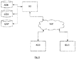
- Figure 6 is a block diagram of a computer system suitable for carrying out a method according to a different exemplary embodiment of the present invention.
- the executable program EXP and the computer file(s) defining the avatar(s) and possibly the three-dimensional scene are stored on memory devices connected to a server SC.
- the memory devices and the overall architecture of the server may be the same as discussed above with reference to figure 5 , except that display controller, display, keyboard and/or pointing device may be missing in the server.
- the server SC is then connected to an administrator system ADS and end user computer EUC via a network NW.
- the overall architectures of the administrator system and of the end user computer may be the same as discussed above with reference to figure 6 , except that the memory devices of the administrator system and the end user computer do not store the executable program EXP and/or the computer file(s) defining the body model and/or skeleton(s). However, the end user computer does store a client program designed for cooperating with the executable program of the server, as it will be discussed below.
- the network NW can be a public network, such as the Internet, or a private network such as an LAN or WAN network, or any combination thereof and can also include PSTN or ISDN sub-networks.
- the network NW can also be wired, such as an Ethernet network, or can be wireless such as a cellular network including EDGE, 3G and 4G wireless cellular systems.
- the wireless network can also be Wi-Fi, Bluetooth, or any other wireless form of communication that is known.
- the network NW is merely exemplary and in no way limits the scope of the present advancements.
- the client program stored in a memory device of the end user computer and executed by a CPU of the latter accesses, via the network NW, a database DB stored by the server SC and containing files defining body models and/or skeletons.
- the server performs the processing as described above, and transmits to the end user computer an image file corresponding to the desired representation of the body model(s) and/or skeleton(s), again using the network NW.
Landscapes
- Engineering & Computer Science (AREA)
- Physics & Mathematics (AREA)
- Theoretical Computer Science (AREA)
- General Physics & Mathematics (AREA)
- General Engineering & Computer Science (AREA)
- Computer Graphics (AREA)
- Software Systems (AREA)
- Geometry (AREA)
- Architecture (AREA)
- Computer Hardware Design (AREA)
- Human Computer Interaction (AREA)
- Processing Or Creating Images (AREA)
- Manipulator (AREA)
Abstract
a) providing a first (SK1) and a second skeleton (SK2) each comprising rotational joints (A, A1, A2, A3, B, E, F) connected by bones, each rotational joint of the second skeleton (E, F) being associated to a respective joint of the first skeleton (A, B);
b) determining a relative configuration of the second skeleton, mapping each joint of the first skeleton associated to a joint of the second skeleton to said joint of the second skeleton;
c) making the first skeleton taking a posture defined by a rotational state for each joint of the first skeleton; and
d) computing transformation matrices for the joints of the second skeletons such that a change of its relative configuration is minimized;
wherein said second skeleton further comprises a prismatic joint (G) on at least one of its bones, step d) comprising determining rotations of the rotational joints and translation of the prismatic joint or joints of the second skeleton such that the change of its relative configuration is minimized.
Description
- The invention relates to a computer-implemented method for making a skeleton of a modeled human or animal body take a posture. More precise, it relates to a method for transferring or "retargeting" a pose taken by a first ("source") skeleton to another ("target") skeleton.
- It relates to the field of computer graphics and it lends itself to several applications such as Computer Aided Design (CAD), ergonomics, video games, etc.
- Digital Human Models (DHMs), as part of CAD systems, are being used extensively for design evaluations and incorporating human factors in the early stages of design.
- A DHM usually comprises a "skeleton" covered by a "skin", even if in some cases it may consists of the skeleton alone. The skeleton is constituted by a set of segments, called "bones" even if they do not necessarily correspond to actual anatomical bones, articulated by rotational joints having one, two or three rotational degrees of freedom. Such models, also known as "avatars", are usually provided in standard postures, such as the so-called "T-pose" (partially spread legs, arms extended horizontally) for human body models. See for instance [Abdel-Malek 2006].
- In order to make the avatar take a particular posture different from the original one, it is necessary to determine a set of rotations of the joints articulating the bones of its skeleton leading to the desired result. From a theoretical standpoint, this corresponds to the problem of inverse kinematics (IK). Several algorithms exist for solving this problem.
- Despite the long history of DHM applications, the lack of proper standardization results in a variety of application-specific models, emulating human postures and movements with varying degrees of accuracy. Several DHMs are then commercially available with diverse capabilities and performances; some emphasize anthropometry and linkage structure accuracy, while others are good at posture/motion modeling and biomechanics, and others stresses behavioral and cognitive aspects.
- The co-existence of multiple skeleton definitions is detrimental as it leads to non-digital continuity between different applications of DHM.
- The invention aims at overcoming the aforementioned drawbacks of the prior art.
- According to an aspect of the invention, as different skeletons may be optimized for different applications, a DHM having two or more skeletons - possibly associated to a single skin SN - is provided. For instance, a first skeleton may be a complex and biologically accurate skeleton, useful e.g. for performing ergonomic analysis, and a second skeleton of the DHM may then be much simpler, achieving a better compromise between complexity and accuracies for real-time animations.
- According to another aspect of the invention, postures are mapped from one skeleton to another, in order to maintain posture synchronization between two different skeletons. This will be called hereafter "retargeting". Retargeting is known by itself, but it is usually applied to skeletons belonging to different DHM.
According to yet another object of the invention, at least one of the skeletons of the DHM (intended to be used as a target of the retargeting operation) is provided with prismatic joints on some or all of its bones. Bones provided with a prismatic joint have a variable length. The additional degree of freedoms provided by the prismatic joints allow ensuring a perfect or near-perfect retargeting even when the target skeleton has substantially less rotational joints than the source skeleton. This, in turns, allows the retargeting process to be done accurately and at a low computational cost. - The invention is not limited to the case of multi-skeleton DHM; for instance it may be used for transferring a pose from a first skeleton, belonging to (or constituting a) first DHM to a second skeleton belonging to (or constituting a) second DHM. Otherwise stated, the first aspect of the invention, mentioned above, id not essential.
- The invention is not even limited to digital human models: it applies to any modeled human or animal body comprising at least one skeleton suitable to be retargeted to another skeleton, belonging to the model or not.
- An object of the present invention, allowing achieving this aim, is then a computer-implemented method for a computer-implemented method for making a skeleton of a modeled human or animal body taking a posture, comprising the steps of:
- a) providing a first skeleton and a second skeleton of at least one digital body model, each of said first and second skeleton comprising a plurality of rotational joints connected by bones, the first skeleton having a greater number of rotational joints than the second skeleton, each rotational joint of the second skeleton being associated to a respective joint of the first skeleton;
- b) determining a relative configuration of the second skeleton, said relative configuration mapping each joint of the first skeleton associated to a joint of the second skeleton to said joint of the second skeleton;
- c) based on one or more inputs from a user, making the first skeleton taking a posture defined by a rotational state for each joint of the first skeleton; and
- d) computing transformation matrices for the joints of the second skeletons such that its relative configuration remains unchanged;
- Another object of the invention is a computer program product, stored on a non-transitory computer-readable data-storage medium, comprising computer-executable instructions to cause a computer system to carry out such a method.
- Yet another object of the invention is a non-transitory computer-readable data-storage medium containing computer-executable instructions to cause a computer system to carry out such a method.
- Yet another object of the invention is a computer system comprising a processor coupled to a memory and a graphical user interface, the memory storing computer-executable instructions to cause the computer system to carry out such a method.
- A further object of the invention is a digital body model comprising a first skeleton and a second skeleton, each of said first and second skeleton comprising a plurality of rotational joints connected by bones, the first skeleton having a greater number of rotational joints than the second skeleton, each rotational joint of the second skeleton being associated to a respective joint of the first skeleton, wherein said second skeleton further comprises a prismatic joint on at least one of its bones.
- Additional features and advantages of the present invention will become apparent from the subsequent description, taken in conjunction with the accompanying drawings, wherein:
-
Figure 1 represents a digital body model comprising a first ("source") skeleton, a second ("target") skeleton and a skin; -
Figures 2A - 2C represent, respectively, a source and a target skeleton in their initial ("zero") pose, the source skeleton taking a different pose and the "retargeting" of the target skeleton; -
Figures 3A - 3F andfigure 4 illustrate different steps of a method according to an embodiment of the invention; -
Figures 5 and6 are block diagrams of respective computer systems suitable for carrying out a method according to different embodiments of the invention. -
Figure 1 represents an exemplary DHM having two skeletons SK1, SK2 associated to a single skin SN. In this exemplary embodiment, skeleton SK1 is be a complex and biologically accurate skeleton, including a large number of rotational joints; such a skeleton is useful e.g. for performing ergonomic analysis, but it is too complex for real-time animation applications. Skeleton SK2 is much simpler (it comprises a smaller number of joints) and achieves a good compromise between complexity and accuracies for real-time animations, but it would be too coarse for ergonomic analysis. Human modeling artists are involved in construction of the simple skeleton SK2 and the related skin to produce plausible skin deformations corresponding to different postures of SK2. -
Figures 2A - 2C illustrate the retargeting operation between SK1 and SK2. -
Figure 2A show portions of skeleton SK1 and SK2, corresponding to the upper body of the DHM, in their initial or "zero" pose. The rotational joints of SK2 are highlighted by circles. Each joint of SK2 is exactly or at least approximately superposed to a corresponding joint of SK1, but the converse is not true, given that SK1 comprises a greater number of joints. - In
figure 2B , skeleton SK1 (acting as a "source" skeleton) has taken a different pose, while SK2 has remained still. It can be seen that the joints of SK1 corresponding to the joints of SK2 (highlighted by a rectangular box) are no longer superposed to the latter. -
Figure 2C shows the result of a retargeting operation: "target" skeleton SK2 has taken a new pose matching that of SK1; corresponding joints of the two skeletons are again almost superposed. - A posture is defined by a configuration of the kinematic structure - i.e. a mathematical representation - of the linkage structure formed by the bones and joints of a skeleton. As each skeleton has its own topology defining its kinematics structure, retargeting is a complex problem, particularly when it is required to transfer a posture from a complex source skeleton to a simple target one (the case considered above, with reference to
figures 2A -2C ). Indeed, as a reduced number of joints implies a smaller possible posture space, mapping from a complex skeleton to a simple one necessarily involves a loss of information, and possible mapping cannot always be achieved (a careful comparison offigures 2A and 2C shows that the relative positions of some joints of the two skeletons has slightly changed, this is particularly visible on the left sides of the figures). - The two skeletons - SK1 and SK2 - are defined independently and therefore, beside a different number of bones and joints, they may also have different kinds of joints with different degrees of freedom (DOF), different coordinate frames. These differences translate into different global transformation matrices, which define the position and orientation of each joint in a global coordinate frame for a given skeleton.
- The first step of the inventive method consists in identifying corresponding joints on the two skeletons. If we consider that the target skeleton SK2 has fewer joints than the source skeleton SK1, this consists in identifying a subset of joints of SK1 corresponding to respective joints of SK2. This has already been discussed with reference to
figures 2A - 2C . In the highly simplified example offigures 3A - 3F (see in particular 3A), the source skeleton SK1 has five joints, labeled A, A1, A2, A3 and B, while the target skeleton has two joints, E and F. Joints A and B of SK1 are associated to joints E and F, respectively; joints A1, A2 and A3 are not associated to any joint of SK2. The association may be performed manually, e.g. by the designer of a multi-skeleton DHM, or automatically, e.g. by automatically identifying the joint of SK1 which is closest to any one of the joints of SK2 when both skeletons are in their initial, or "zero", pose. - Then, the relative transformation matrix of each joint of SK1 (e.g. joint B) with respect to the corresponding joint of SK2 (e.g. joint F) is computed. Let TB the initial transformation matrix of joint B, expressing its position and orientation with respect to a point serving as a global origin, or root:


- The configuration of each skeleton is defined by the transformation matrices of all its joints.
- The (initial) relative transformation matrix of joint F with respect to B,


- In the example of
figure 3A , joints B and F coincide and have a same orientation, i.e.
- The relative configuration of the source skeleton SK1 is defined by the relative transformation matrices of all its joints.
- When the pose of the source skeleton SK1 changes, joint B takes a different configuration (position and/or orientation along three rotation axes), which will be designated by B1 (see
figures 3B ) and described by a different transformation matrix T B1 . Retargeting, or posture synchronization, consists in finding a new configuration F1 for joint F, described by transformation matrix T F1 such that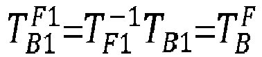
- Let the distance between A and B be dAB, which is equal to the norm of

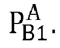

- The compensatory movement to displace the joint F to match the position of B1 can be achieved only by using joint E. Let the unit vectors of EF and EB1 be P1 and P2 (see
figure 3C ), whose values can be computed from TF and TB1. Let θEswing be the angle between P1, P2 and let P3 be the unit vector normal to P1 and P2 (seefigure 4 ). These parameters can all be determined from the transformation matrices. If joint E is rotated about axis P3 with magnitude θEswing, then joint F reaches location F'. However, in general,
figures 3A and 3C shows that while B and F coincide, B1 and F' do not. - Therefore, rotating the joints of the target skeleton SK2 is not sufficient, in general, to achieve perfect posture synchronization between SK1 and SK2. And indeed, in the prior art, retargeting often fails to achieve an exact posture synchronization between skeletons, and only allows to minimize an error in relative configuration change.
- According to the invention, this problem is solved by providing bone EF with a prismatic joint G (see
figure 3D ) which allows changing its length. By acting on both rotational joint E (which undergoes a rotation by angle θEswing about axis P3) and prismatic joint G (which undergoes a translation of magnitude dEF-dAB1) it is possible to displace point F to a position F1 coinciding with that of B1, as shown onfigure 3E . - From a formal point of view, the transformation of F to F1 corresponds to a transformation matrix

Eswing is the rotation matrix for a rotation by θEswing about axis P3 and
- This matrix is appended (i.e. post-multiplied) to the global matrix TE to obtain global


- However, matching the position of joint F with B1 is not a sufficient condition for posture mapping. Joint F also needs to be re oriented in order to ensure that the condition

figure 3E . An additional rotation RφFswing and additional transformation matrix TφFswing can be computed to match the unit vector f1 with b1 as shown onfigure 3F using the same approach discussed above with reference tofigure 3C . - Moreover, in three dimensions it is also necessary to account for the existence of a twist component Tφ
Ftwist of the transformation matrix. - But matching these two unit vectors will not necessarily satisfy the initial relative configuration constraint (equation 3) because of existence of twist component Tφ
Ftwist . Therefore its essential to determine the twist component required to satisfy the constraint.
TB and T B1 are the initial and final global transformations of the joint B. Similarly TF, TF1 are the initial and final global transformations of joint F. The initial relative configuration of joints B and F is given by

- TF1 is combination of two components TφFswing and TφFtwist : TF1 = TφFswingTφFtwist where TφFswing is easily found from vectors f1 and b1.
- Therefore:

- At this point, the three transformation matrices TEnew,TφFswing and TφFtwist allow computing the new configuration of joint F. It should be noted that, out of the seven DOF available, six are used to achieve posture synchronization. One DOF (twist parameter) is left at joint E and can be used to address the issues like joint ranges of motion at the joint F and possible distortions of the skin deformation which is attached the link EF. Indeed, in most practical cases it is required that the whole process of retargeting is carried out without disturbing the visual appearance of the skin. In these cases its not enough to get exact solution for retargeting but also the appearance of the skin should be kept intact without distortions. The "modular" retargeting procedure described above, treating one bone at a time, allows to isolate one DOF to deal with additional constraints. In particular, this DOF can be used to preserve the natural appearance of the skin. Additionally, in some cases, the retargeting solution may drive some joints out of their allowed motion range; in this scenario, the remaining DOF can be used to ensure that the retargeting solutions respects the constraints on the joint positions and orientations.
- The same procedure is applied step by step to all the joints of SK2, starting from a root node till the end effectors.
- The inventive method can be performed by a suitably-programmed general-purpose computer or computer system, possibly including a computer network, storing a suitable program in non-transitory form on a computer-readable medium such as a hard disk, a solid state disk or a CD-ROM and executing said program using its microprocessor(s) and memory.
- A computer suitable for carrying out a method according to an exemplary embodiment of the present invention is described with reference to
figure 5 . Infigure 5 , the computer includes a Central Processing Unit CPU which performs the processes described above. The process can be stored as an executable program, i.e. a set of computer-readable instructions in memory, such as RAM M1 or ROM M2, or on hard disk drive (HDD) or solid-state driver (SDD) M3, DVD/CD drive M4, or can be stored remotely. Moreover, one or more computer files defining one or more digital body model and/or skeleton may also be stored on one or more of memory devices M1 to M4, or remotely. - The claimed invention is not limited by the form of the computer-readable media on which the computer-readable instructions and/or the digital files of the inventive process are stored. For example, the instructions and files can be stored on CDs, DVDs, in FLASH memory, RAM, ROM, PROM, EPROM, EEPROM, hard disk or any other information processing device with which the computer communicates, such as a server or another computer. The program and the files can be stored on a same memory device or on different memory devices.
- Further, a computer program suitable for carrying out the inventive method can be provided as a utility application, background daemon, or component of an operating system, or combination thereof, executing in conjunction with CPU 800 and an operating system such as Microsoft Windows 10, UNIX, Solaris, LINUX, Apple MAC-OS and other systems known to those skilled in the art.
- The Central Processing Unit CPU can be a Xenon processor from Intel of America or an Opteron processor from AMD of America, or can be other processor types, such as a Freescale ColdFire, IMX, or ARM processor from Freescale Corporation of America. Alternatively, the Central Processing Unit can be a processor such as a Core2 Duo from Intel Corporation of America, or can be implemented on an FPGA, ASIC, PLD or using discrete logic circuits, as one of ordinary skill in the art would recognize. Further, the Central Processing Unit can be implemented as multiple processors cooperatively working to perform the computer-readable instructions of the inventive processes described above.
- The computer in
figure 5 also includes a network interface NI, such as an Intel Ethernet PRO network interface card from Intel Corporation of America, for interfacing with a network, such as a local area network (LAN), wide area network (WAN), the Internet and the like. The Computer Aided Design station further includes a display controller DC, such as a NVIDIA GeForce GTX graphics adaptor from NVIDIA Corporation of America for interfacing with display DY, such as a Hewlett Packard HPL2445w LCD monitor. A general purpose I/O interface IF interfaces with a keyboard KB and pointing device PD, such as a roller ball, mouse, touchpad and the like. The display, the keyboard and the pointing device, together with the display controller and the I/O interfaces, form a graphical user interface, used by the user to provide input commands - e.g. to move the target point, define parameters etc. - and by the Computer Aided Design station for displaying the three-dimensional scene including the avatar. - Disk controller DKC connects HDD M3 and DVD/CD M4 with communication bus CBS, which can be an ISA, EISA, VESA, PCI, or similar, for interconnecting all of the components of the Computer Aided Design station.
- A description of the general features and functionality of the display, keyboard, pointing device, as well as the display controller, disk controller, network interface and I/O interface is omitted herein for brevity as these features are known.
-
Figure 6 is a block diagram of a computer system suitable for carrying out a method according to a different exemplary embodiment of the present invention. - In
figure 6 , the executable program EXP and the computer file(s) defining the avatar(s) and possibly the three-dimensional scene are stored on memory devices connected to a server SC. The memory devices and the overall architecture of the server may be the same as discussed above with reference tofigure 5 , except that display controller, display, keyboard and/or pointing device may be missing in the server. - The server SC is then connected to an administrator system ADS and end user computer EUC via a network NW.
- The overall architectures of the administrator system and of the end user computer may be the same as discussed above with reference to
figure 6 , except that the memory devices of the administrator system and the end user computer do not store the executable program EXP and/or the computer file(s) defining the body model and/or skeleton(s). However, the end user computer does store a client program designed for cooperating with the executable program of the server, as it will be discussed below. - As can be appreciated, the network NW can be a public network, such as the Internet, or a private network such as an LAN or WAN network, or any combination thereof and can also include PSTN or ISDN sub-networks. The network NW can also be wired, such as an Ethernet network, or can be wireless such as a cellular network including EDGE, 3G and 4G wireless cellular systems. The wireless network can also be Wi-Fi, Bluetooth, or any other wireless form of communication that is known. Thus, the network NW is merely exemplary and in no way limits the scope of the present advancements.
- The client program stored in a memory device of the end user computer and executed by a CPU of the latter accesses, via the network NW, a database DB stored by the server SC and containing files defining body models and/or skeletons. The server performs the processing as described above, and transmits to the end user computer an image file corresponding to the desired representation of the body model(s) and/or skeleton(s), again using the network NW.
- Although only one administrator system ADS and one end user system EUX are shown, the system can support any number of administrator systems and/or end user systems without limitation. Similarly, multiple servers can also be implemented in the system without departing from the scope of the present invention.
- Any processes described herein should be understood as representing modules, segments, or portions of code which include one or more executable instructions for implementing specific logical functions or steps in the process, and alternate implementations are included within the scope of the exemplary embodiment of the present invention.
- [Abdel-Malek 2006] Abdel-Malek, K., Yang, J., Marler, T., et al. (2006), "Towards a New Generation of Virtual Humans", International Journal of Human Factors Modeling and Simulation, 1,1, 2-39.
Claims (13)
- A computer-implemented method for making a skeleton of a modeled human or animal body taking a posture, comprising the steps of:a) providing a first skeleton (SK1) and a second skeleton (SK2) of at least one digital body model, each of said first and second skeleton comprising a plurality of rotational joints (A, A1, A2, A3, B, E, F) connected by bones, the first skeleton having a greater number of rotational joints than the second skeleton, each rotational joint of the second skeleton (E, F) being associated to a respective joint of the first skeleton (A, B);b) determining a relative configuration of the second skeleton, said relative configuration mapping each joint of the first skeleton associated to a joint of the second skeleton to said joint of the second skeleton;c) based on one or more inputs from a user, making the first skeleton taking a posture defined by a rotational state for each joint of the first skeleton; andd) computing transformation matrices for the joints of the second skeletons such that its relative configuration remains unchanged; wherein said second skeleton further comprises a prismatic joint (G) on at least one of its bones, step d) comprising determining rotations of the rotational joints and translation of the prismatic joint or joints of the second skeleton such that the change of its relative configuration is minimized.
- The method of claim 1 wherein the second skeleton comprises a prismatic joint on all of its bones.
- The method of claim 2 wherein step d) comprises determining rotations of the rotational joints and translation of the prismatic joint or joints of the second skeleton such that its relative configuration remains unchanged.
- The method of any one of the preceding claims wherein step d) comprises computing a said transformation matrix for each joint of the second skeleton by considering said joints in succession, starting from a root joint.
- The method of any one of the preceding claims wherein step a) comprises making the first and the second skeleton taking respective initial postures.
- The method of any one of the preceding claims further comprising the following step:
e) applying the computed transformation matrices to the joints of the second skeleton, making it take a posture matching that of the first skeleton. - The method of claim 6 further comprising the following step:
f) displaying, on a computer screen, at least one of the second skeleton and of a skin (SN) associated to it. - The method of any one of the preceding claims wherein the first skeleton and the second skeleton belong to a same digital body model.
- A computer program product, stored on a non-transitory computer-readable data-storage medium (M1 - M4), comprising computer-executable instructions to cause a computer system to carry out a method according to any of the preceding claims.
- A non-transitory computer-readable data-storage medium (M1 - M4) containing computer-executable instructions (EXP) to cause a computer system to carry out a method according to any of claims 1 to 8.
- A computer system comprising a processor (P) coupled to a memory (M1 - M4) and a graphical user interface (KB, PD, DC, DY), the memory storing computer-executable instructions (EXP) to cause the computer system to carry out a method according to any of claims 1 to 8.
- A digital body model comprising a first skeleton (SK1) and a second skeleton (SK2), each of said first and second skeleton comprising a plurality of rotational joints (A, A1, A2, A3, B, E, F) connected by bones, the first skeleton having a greater number of rotational joints than the second skeleton, each rotational joint of the second skeleton (E, F) being associated to a respective joint of the first skeleton (A, B), wherein said second skeleton further comprises a prismatic joint (G) on at least one of its bones.
- The digital body model of claim 12 wherein the second skeleton comprises a prismatic joint on all of its bones.
Priority Applications (4)
| Application Number | Priority Date | Filing Date | Title |
|---|---|---|---|
| EP19306366.6A EP3813023A1 (en) | 2019-10-21 | 2019-10-21 | Computer-implemented method for making a skeleton of a modeled body take a posture |
| US17/070,875 US11410402B2 (en) | 2019-10-21 | 2020-10-14 | Computer-implemented method for making a skeleton of a modeled body take a posture |
| JP2020173428A JP7704514B2 (en) | 2019-10-21 | 2020-10-14 | Computer-implemented method for posing a modeled body skeleton - Patents.com |
| CN202011095370.XA CN112767528A (en) | 2019-10-21 | 2020-10-14 | Computer-implemented method for posing a skeleton of a modeled body |
Applications Claiming Priority (1)
| Application Number | Priority Date | Filing Date | Title |
|---|---|---|---|
| EP19306366.6A EP3813023A1 (en) | 2019-10-21 | 2019-10-21 | Computer-implemented method for making a skeleton of a modeled body take a posture |
Publications (1)
| Publication Number | Publication Date |
|---|---|
| EP3813023A1 true EP3813023A1 (en) | 2021-04-28 |
Family
ID=68583293
Family Applications (1)
| Application Number | Title | Priority Date | Filing Date |
|---|---|---|---|
| EP19306366.6A Pending EP3813023A1 (en) | 2019-10-21 | 2019-10-21 | Computer-implemented method for making a skeleton of a modeled body take a posture |
Country Status (4)
| Country | Link |
|---|---|
| US (1) | US11410402B2 (en) |
| EP (1) | EP3813023A1 (en) |
| JP (1) | JP7704514B2 (en) |
| CN (1) | CN112767528A (en) |
Families Citing this family (5)
| Publication number | Priority date | Publication date | Assignee | Title |
|---|---|---|---|---|
| US10796469B2 (en) * | 2017-07-28 | 2020-10-06 | Baobab Studios Inc. | Systems and methods for real-time complex character animations and interactivity |
| CN113386128B (en) * | 2021-05-11 | 2022-06-10 | 华南理工大学 | Body potential interaction method for multi-degree-of-freedom robot |
| CN113706699B (en) * | 2021-10-27 | 2022-02-08 | 腾讯科技(深圳)有限公司 | Data processing method and device, electronic equipment and computer readable storage medium |
| EP4604065A1 (en) * | 2024-02-13 | 2025-08-20 | Dassault Systèmes | Alignment of virtual manikins |
| CN119783447A (en) * | 2024-12-10 | 2025-04-08 | 网易(杭州)网络有限公司 | Cloth simulation method, device, electronic equipment, storage medium and program product |
Citations (2)
| Publication number | Priority date | Publication date | Assignee | Title |
|---|---|---|---|---|
| US9508177B2 (en) * | 2011-12-06 | 2016-11-29 | CELSYS, Inc. | Method of controlling skeleton model, and recording medium therewith |
| US9747717B2 (en) * | 2015-05-13 | 2017-08-29 | Intel Corporation | Iterative closest point technique based on a solution of inverse kinematics problem |
Family Cites Families (6)
| Publication number | Priority date | Publication date | Assignee | Title |
|---|---|---|---|---|
| EP3324366A1 (en) * | 2016-11-22 | 2018-05-23 | Dassault Systèmes | Computer-implemented method for simulating a body taking a posture |
| EP3324365A1 (en) * | 2016-11-22 | 2018-05-23 | Dassault Systèmes | Computer-implemented method for simulating a body taking a posture, in particular to look at a target |
| EP3552199A4 (en) * | 2016-12-13 | 2020-06-24 | Deepmotion, Inc. | Improved virtual reality system using multiple force arrays for a solver |
| JP7262937B2 (en) * | 2018-06-29 | 2023-04-24 | キヤノン株式会社 | Information processing device, information processing method, and program |
| CN109509241B (en) * | 2018-08-16 | 2023-06-23 | 北京航空航天大学青岛研究院 | Quaternary-based character animation bone redirecting method for digital |
| JP7375456B2 (en) * | 2019-10-18 | 2023-11-08 | 株式会社アイシン | Toe position estimation device and fingertip position estimation device |
-
2019
- 2019-10-21 EP EP19306366.6A patent/EP3813023A1/en active Pending
-
2020
- 2020-10-14 US US17/070,875 patent/US11410402B2/en active Active
- 2020-10-14 JP JP2020173428A patent/JP7704514B2/en active Active
- 2020-10-14 CN CN202011095370.XA patent/CN112767528A/en active Pending
Patent Citations (2)
| Publication number | Priority date | Publication date | Assignee | Title |
|---|---|---|---|---|
| US9508177B2 (en) * | 2011-12-06 | 2016-11-29 | CELSYS, Inc. | Method of controlling skeleton model, and recording medium therewith |
| US9747717B2 (en) * | 2015-05-13 | 2017-08-29 | Intel Corporation | Iterative closest point technique based on a solution of inverse kinematics problem |
Non-Patent Citations (6)
| Title |
|---|
| "Advances in intelligent systems and computing : AISC", vol. 822, 7 August 2018, SPRINGER, Berlin, ISSN: 2194-5357, article LEYDE BRICENO ET AL: "MakeHuman: A Review of the Modelling Framework : Volume V: Human Simulation and Virtual Environments, Work With Computing Systems (WWCS), Process Control", pages: 224 - 232, XP055668753, DOI: 10.1007/978-3-319-96077-7_23 * |
| ABDEL-MALEK, K.YANG, J.MARLER, T. ET AL.: "Towards a New Generation of Virtual Humans", INTERNATIONAL JOURNAL OF HUMAN FACTORS MODELING AND SIMULATION, vol. 1, no. 1, 2006, pages 2 - 39 |
| ANDREW FENG ET AL: "Fast, automatic character animation pipelines", COMPUTER ANIMATION AND VIRTUAL WORLDS, vol. 25, no. 1, 1 January 2014 (2014-01-01), GB, pages 3 - 16, XP055667996, ISSN: 1546-4261, DOI: 10.1002/cav.1560 * |
| KARIM ABDEL-MALEK ET AL: "Towards a new generation of virtual humans", INTERNATIONAL JOURNAL OF HUMAN FACTORS MODELLING AND SIMULATION, 1 January 2006 (2006-01-01), pages 2 - 39, XP055668545, Retrieved from the Internet <URL:https://pdfs.semanticscholar.org/601f/4265938c3b1b243be6480e6c04976459a93c.pdf> [retrieved on 20100101], DOI: 10.1504/IJHFMS.2006.011680 * |
| MONZANI J-S ET AL: "Using an Intermediate Skeleton and Inverse Kinematics for Motion Retargeting", PROCEEDINGS OF THE EUROGRAPHICS CONFERENCE, XX, XX, vol. 19, no. 3, 20 August 2000 (2000-08-20), pages 11 - 19, XP002503420 * |
| XI CHEN ET AL: "Sequence Alignment for RGB-D and Motion Capture Skeletons", 26 June 2013, IMAGE ANALYSIS AND RECOGNITION, SPRINGER BERLIN HEIDELBERG, BERLIN, HEIDELBERG, PAGE(S) 630 - 639, ISBN: 978-3-642-39093-7, XP047031368 * |
Also Published As
| Publication number | Publication date |
|---|---|
| JP7704514B2 (en) | 2025-07-08 |
| US11410402B2 (en) | 2022-08-09 |
| JP2021068438A (en) | 2021-04-30 |
| CN112767528A (en) | 2021-05-07 |
| US20210118241A1 (en) | 2021-04-22 |
Similar Documents
| Publication | Publication Date | Title |
|---|---|---|
| US11410402B2 (en) | Computer-implemented method for making a skeleton of a modeled body take a posture | |
| US10482647B2 (en) | Computer-implemented method for simulating a body taking a posture | |
| EP1288867B1 (en) | Method for generating motion | |
| JP4452272B2 (en) | Joint component framework for modeling complex joint movements | |
| US20080204457A1 (en) | Rig Baking | |
| JP5490080B2 (en) | Skeleton model attitude control method and program | |
| US10319135B2 (en) | Computer-implemented method for simulating a body taking a posture, in particular to look at a target | |
| US9892485B2 (en) | System and method for mesh distance based geometry deformation | |
| US20040263518A1 (en) | Defrobulated angles for character joint representation | |
| CN111161419A (en) | Three-dimensional model cutting method, device and storage medium | |
| Le Naour et al. | Skeletal mesh animation driven by few positional constraints | |
| Celikcan et al. | Example‐Based Retargeting of Human Motion to Arbitrary Mesh Models | |
| US20240378816A1 (en) | Data optimization methods for dynamic cut boundary | |
| Wang et al. | Shape-aware skeletal deformation for 2D characters | |
| EP2384714A1 (en) | A method for defining working space limits in robotic surgery | |
| CN116597056A (en) | An animation processing method, device, equipment and storage medium | |
| US20250259391A1 (en) | Alignment of virtual manikins | |
| Danckaers et al. | Adaptable digital human models from 3D body scans | |
| Liao et al. | Development of a patient-specific surgical simulator based on virtual reality | |
| JPH10269380A (en) | Automatic perspective drawing three-dimensional nurb curved line storing method and its device | |
| JP2005322097A (en) | Object image model animation display apparatus, object image model animation display method, and object image model animation display program | |
| CN116524126A (en) | Human body model processing method and device and electronic equipment | |
| CN119577864A (en) | Method for modifying a 3D model by using a partial sketch in an AR/VR environment | |
| CN121600138A (en) | Animated character shaping method, electronic device, and storage medium |
Legal Events
| Date | Code | Title | Description |
|---|---|---|---|
| PUAI | Public reference made under article 153(3) epc to a published international application that has entered the european phase |
Free format text: ORIGINAL CODE: 0009012 |
|
| STAA | Information on the status of an ep patent application or granted ep patent |
Free format text: STATUS: THE APPLICATION HAS BEEN PUBLISHED |
|
| AK | Designated contracting states |
Kind code of ref document: A1 Designated state(s): AL AT BE BG CH CY CZ DE DK EE ES FI FR GB GR HR HU IE IS IT LI LT LU LV MC MK MT NL NO PL PT RO RS SE SI SK SM TR |
|
| AX | Request for extension of the european patent |
Extension state: BA ME |
|
| STAA | Information on the status of an ep patent application or granted ep patent |
Free format text: STATUS: REQUEST FOR EXAMINATION WAS MADE |
|
| 17P | Request for examination filed |
Effective date: 20210712 |
|
| RBV | Designated contracting states (corrected) |
Designated state(s): AL AT BE BG CH CY CZ DE DK EE ES FI FR GB GR HR HU IE IS IT LI LT LU LV MC MK MT NL NO PL PT RO RS SE SI SK SM TR |
|
| STAA | Information on the status of an ep patent application or granted ep patent |
Free format text: STATUS: EXAMINATION IS IN PROGRESS |
|
| 17Q | First examination report despatched |
Effective date: 20231130 |