EP3812965A1 - Text region identification method and device - Google Patents
Text region identification method and device Download PDFInfo
- Publication number
- EP3812965A1 EP3812965A1 EP19845554.5A EP19845554A EP3812965A1 EP 3812965 A1 EP3812965 A1 EP 3812965A1 EP 19845554 A EP19845554 A EP 19845554A EP 3812965 A1 EP3812965 A1 EP 3812965A1
- Authority
- EP
- European Patent Office
- Prior art keywords
- information
- copy area
- copy
- pixels
- acquire
- Prior art date
- Legal status (The legal status is an assumption and is not a legal conclusion. Google has not performed a legal analysis and makes no representation as to the accuracy of the status listed.)
- Pending
Links
Images




Classifications
-
- G—PHYSICS
- G06—COMPUTING OR CALCULATING; COUNTING
- G06N—COMPUTING ARRANGEMENTS BASED ON SPECIFIC COMPUTATIONAL MODELS
- G06N3/00—Computing arrangements based on biological models
- G06N3/02—Neural networks
- G06N3/08—Learning methods
- G06N3/088—Non-supervised learning, e.g. competitive learning
-
- G—PHYSICS
- G06—COMPUTING OR CALCULATING; COUNTING
- G06V—IMAGE OR VIDEO RECOGNITION OR UNDERSTANDING
- G06V10/00—Arrangements for image or video recognition or understanding
- G06V10/20—Image preprocessing
- G06V10/24—Aligning, centring, orientation detection or correction of the image
- G06V10/242—Aligning, centring, orientation detection or correction of the image by image rotation, e.g. by 90 degrees
-
- G—PHYSICS
- G06—COMPUTING OR CALCULATING; COUNTING
- G06F—ELECTRIC DIGITAL DATA PROCESSING
- G06F18/00—Pattern recognition
- G06F18/20—Analysing
- G06F18/25—Fusion techniques
- G06F18/253—Fusion techniques of extracted features
-
- G—PHYSICS
- G06—COMPUTING OR CALCULATING; COUNTING
- G06N—COMPUTING ARRANGEMENTS BASED ON SPECIFIC COMPUTATIONAL MODELS
- G06N3/00—Computing arrangements based on biological models
- G06N3/02—Neural networks
- G06N3/04—Architecture, e.g. interconnection topology
-
- G—PHYSICS
- G06—COMPUTING OR CALCULATING; COUNTING
- G06N—COMPUTING ARRANGEMENTS BASED ON SPECIFIC COMPUTATIONAL MODELS
- G06N3/00—Computing arrangements based on biological models
- G06N3/02—Neural networks
- G06N3/04—Architecture, e.g. interconnection topology
- G06N3/044—Recurrent networks, e.g. Hopfield networks
- G06N3/0442—Recurrent networks, e.g. Hopfield networks characterised by memory or gating, e.g. long short-term memory [LSTM] or gated recurrent units [GRU]
-
- G—PHYSICS
- G06—COMPUTING OR CALCULATING; COUNTING
- G06N—COMPUTING ARRANGEMENTS BASED ON SPECIFIC COMPUTATIONAL MODELS
- G06N3/00—Computing arrangements based on biological models
- G06N3/02—Neural networks
- G06N3/04—Architecture, e.g. interconnection topology
- G06N3/045—Combinations of networks
-
- G—PHYSICS
- G06—COMPUTING OR CALCULATING; COUNTING
- G06N—COMPUTING ARRANGEMENTS BASED ON SPECIFIC COMPUTATIONAL MODELS
- G06N3/00—Computing arrangements based on biological models
- G06N3/02—Neural networks
- G06N3/04—Architecture, e.g. interconnection topology
- G06N3/045—Combinations of networks
- G06N3/0455—Auto-encoder networks; Encoder-decoder networks
-
- G—PHYSICS
- G06—COMPUTING OR CALCULATING; COUNTING
- G06N—COMPUTING ARRANGEMENTS BASED ON SPECIFIC COMPUTATIONAL MODELS
- G06N3/00—Computing arrangements based on biological models
- G06N3/02—Neural networks
- G06N3/04—Architecture, e.g. interconnection topology
- G06N3/0464—Convolutional networks [CNN, ConvNet]
-
- G—PHYSICS
- G06—COMPUTING OR CALCULATING; COUNTING
- G06N—COMPUTING ARRANGEMENTS BASED ON SPECIFIC COMPUTATIONAL MODELS
- G06N3/00—Computing arrangements based on biological models
- G06N3/02—Neural networks
- G06N3/08—Learning methods
-
- G—PHYSICS
- G06—COMPUTING OR CALCULATING; COUNTING
- G06T—IMAGE DATA PROCESSING OR GENERATION, IN GENERAL
- G06T7/00—Image analysis
- G06T7/0002—Inspection of images, e.g. flaw detection
-
- G—PHYSICS
- G06—COMPUTING OR CALCULATING; COUNTING
- G06T—IMAGE DATA PROCESSING OR GENERATION, IN GENERAL
- G06T7/00—Image analysis
- G06T7/70—Determining position or orientation of objects or cameras
- G06T7/73—Determining position or orientation of objects or cameras using feature-based methods
-
- G—PHYSICS
- G06—COMPUTING OR CALCULATING; COUNTING
- G06V—IMAGE OR VIDEO RECOGNITION OR UNDERSTANDING
- G06V10/00—Arrangements for image or video recognition or understanding
- G06V10/20—Image preprocessing
- G06V10/25—Determination of region of interest [ROI] or a volume of interest [VOI]
-
- G—PHYSICS
- G06—COMPUTING OR CALCULATING; COUNTING
- G06V—IMAGE OR VIDEO RECOGNITION OR UNDERSTANDING
- G06V10/00—Arrangements for image or video recognition or understanding
- G06V10/20—Image preprocessing
- G06V10/26—Segmentation of patterns in the image field; Cutting or merging of image elements to establish the pattern region, e.g. clustering-based techniques; Detection of occlusion
- G06V10/267—Segmentation of patterns in the image field; Cutting or merging of image elements to establish the pattern region, e.g. clustering-based techniques; Detection of occlusion by performing operations on regions, e.g. growing, shrinking or watersheds
-
- G—PHYSICS
- G06—COMPUTING OR CALCULATING; COUNTING
- G06V—IMAGE OR VIDEO RECOGNITION OR UNDERSTANDING
- G06V10/00—Arrangements for image or video recognition or understanding
- G06V10/40—Extraction of image or video features
- G06V10/44—Local feature extraction by analysis of parts of the pattern, e.g. by detecting edges, contours, loops, corners, strokes or intersections; Connectivity analysis, e.g. of connected components
- G06V10/443—Local feature extraction by analysis of parts of the pattern, e.g. by detecting edges, contours, loops, corners, strokes or intersections; Connectivity analysis, e.g. of connected components by matching or filtering
- G06V10/449—Biologically inspired filters, e.g. difference of Gaussians [DoG] or Gabor filters
- G06V10/451—Biologically inspired filters, e.g. difference of Gaussians [DoG] or Gabor filters with interaction between the filter responses, e.g. cortical complex cells
- G06V10/454—Integrating the filters into a hierarchical structure, e.g. convolutional neural networks [CNN]
-
- G—PHYSICS
- G06—COMPUTING OR CALCULATING; COUNTING
- G06V—IMAGE OR VIDEO RECOGNITION OR UNDERSTANDING
- G06V10/00—Arrangements for image or video recognition or understanding
- G06V10/70—Arrangements for image or video recognition or understanding using pattern recognition or machine learning
- G06V10/82—Arrangements for image or video recognition or understanding using pattern recognition or machine learning using neural networks
-
- G—PHYSICS
- G06—COMPUTING OR CALCULATING; COUNTING
- G06V—IMAGE OR VIDEO RECOGNITION OR UNDERSTANDING
- G06V10/00—Arrangements for image or video recognition or understanding
- G06V10/70—Arrangements for image or video recognition or understanding using pattern recognition or machine learning
- G06V10/84—Arrangements for image or video recognition or understanding using pattern recognition or machine learning using probabilistic graphical models from image or video features, e.g. Markov models or Bayesian networks
-
- G—PHYSICS
- G06—COMPUTING OR CALCULATING; COUNTING
- G06V—IMAGE OR VIDEO RECOGNITION OR UNDERSTANDING
- G06V20/00—Scenes; Scene-specific elements
- G06V20/60—Type of objects
- G06V20/62—Text, e.g. of license plates, overlay texts or captions on TV images
-
- G—PHYSICS
- G06—COMPUTING OR CALCULATING; COUNTING
- G06V—IMAGE OR VIDEO RECOGNITION OR UNDERSTANDING
- G06V30/00—Character recognition; Recognising digital ink; Document-oriented image-based pattern recognition
- G06V30/10—Character recognition
- G06V30/14—Image acquisition
- G06V30/148—Segmentation of character regions
- G06V30/153—Segmentation of character regions using recognition of characters or words
-
- G—PHYSICS
- G06—COMPUTING OR CALCULATING; COUNTING
- G06V—IMAGE OR VIDEO RECOGNITION OR UNDERSTANDING
- G06V30/00—Character recognition; Recognising digital ink; Document-oriented image-based pattern recognition
- G06V30/10—Character recognition
- G06V30/19—Recognition using electronic means
- G06V30/191—Design or setup of recognition systems or techniques; Extraction of features in feature space; Clustering techniques; Blind source separation
- G06V30/19173—Classification techniques
-
- G—PHYSICS
- G06—COMPUTING OR CALCULATING; COUNTING
- G06N—COMPUTING ARRANGEMENTS BASED ON SPECIFIC COMPUTATIONAL MODELS
- G06N3/00—Computing arrangements based on biological models
- G06N3/02—Neural networks
- G06N3/04—Architecture, e.g. interconnection topology
- G06N3/044—Recurrent networks, e.g. Hopfield networks
-
- G—PHYSICS
- G06—COMPUTING OR CALCULATING; COUNTING
- G06T—IMAGE DATA PROCESSING OR GENERATION, IN GENERAL
- G06T2207/00—Indexing scheme for image analysis or image enhancement
- G06T2207/20—Special algorithmic details
- G06T2207/20016—Hierarchical, coarse-to-fine, multiscale or multiresolution image processing; Pyramid transform
-
- G—PHYSICS
- G06—COMPUTING OR CALCULATING; COUNTING
- G06T—IMAGE DATA PROCESSING OR GENERATION, IN GENERAL
- G06T2207/00—Indexing scheme for image analysis or image enhancement
- G06T2207/20—Special algorithmic details
- G06T2207/20072—Graph-based image processing
-
- G—PHYSICS
- G06—COMPUTING OR CALCULATING; COUNTING
- G06T—IMAGE DATA PROCESSING OR GENERATION, IN GENERAL
- G06T2207/00—Indexing scheme for image analysis or image enhancement
- G06T2207/20—Special algorithmic details
- G06T2207/20076—Probabilistic image processing
-
- G—PHYSICS
- G06—COMPUTING OR CALCULATING; COUNTING
- G06T—IMAGE DATA PROCESSING OR GENERATION, IN GENERAL
- G06T2207/00—Indexing scheme for image analysis or image enhancement
- G06T2207/20—Special algorithmic details
- G06T2207/20084—Artificial neural networks [ANN]
-
- G—PHYSICS
- G06—COMPUTING OR CALCULATING; COUNTING
- G06T—IMAGE DATA PROCESSING OR GENERATION, IN GENERAL
- G06T2207/00—Indexing scheme for image analysis or image enhancement
- G06T2207/30—Subject of image; Context of image processing
- G06T2207/30168—Image quality inspection
Definitions
- This disclosure relates to the technical field of image processing, and particularly to a copy area identification method and device.
- a large number of commodity advertisements are presented in the form of images inside and outside e-commerce websites every day, and the stock of these advertising images has reached ten billion level with a daily increment of at least several hundred thousand.
- a platform will make a copy design specification of images, and manually audit them after the images are uploaded by users, which usually costs a large amount of time and manpower.
- a copy area identification method comprising: extracting feature information of multiple layers from an image to be processed; encoding the feature of the multiple layers information respectively, and jointly decoding according to encoded information of the multiple layers to acquire a jointly decoded output; acquiring information of pixels according to the jointly decoded output, wherein the information of the pixels comprises rotation angle information of the copy area, and a distance between each of the pixels and a border of the copy area; and determining a position of a border of the copy area according to the information of the pixels.
- acquiring pixel information according to the jointly decoded output comprises: acquiring the information of the pixels according to the jointly decoded output comprises: fusing the jointly decoded output of each of the pixels with at least one of the jointly decoded outputs of a previous pixel or a next pixel to acquire fused decoded information; and acquiring the information of the pixels according to output of the fused decoded information
- the feature information of the multiple layers is extracted by a Convolutional Neural Network (CNN).
- CNN Convolutional Neural Network
- encoding the feature information extracted respectively comprises: inputting the feature information into a Graph Convolutional Network (GCN) respectively to acquire the encoded information of each layer of the multiple layers.
- GCN Graph Convolutional Network
- the GCN convolves each feature by a 1*k convolution kernel and then by a k*1 convolution kernel to acquire a first code, wherein k is a preset constant; convolves each of the feature by a k*1 convolution kernel and then by a 1*k convolution kernel to acquire a second code; and sums the first code and the second code, convolves the summed result with a convolution kernel and outputs a convolved result, to acquire the encoded information.
- jointly decoding according to the encoded information of the multiple layers comprises: decoding the highest layer of the feature information to acquire a highest layer decoded output; and in a sequence of layers from high to low, jointly decoding by using a decoded output of a upper layer and an encoded information of a current layer, and outputting a jointly decoded result to a next layer until the current layer is the lowest layer, then outputting the jointly decoded output.
- jointly decoding by using the decoded output of the upper layer and the encoded information of the current layer comprises: upsampling the encoded information of the current layer to double the amount of the encoded information, then combining an upsampled result with the decoded output of the upper layer, and then outputting a convolved result after convolving the combined information with a convolve kernel.
- acquiring the information of the pixels according to the fused decoded information comprises: acquiring the rotation angle information of the copy area, and the distance between each of the pixels and the border of the copy area in four directions by convolving the fused decoded information by a depth of 5; and determining the copy area according to the information of the pixels comprises: determining the position of the border of the copy area by a non-maximum suppression algorithm according to the rotation angle information of the copy area, and the distance between each of the pixels and the border of the copy in the four directions.
- acquiring the information of the pixels according to the fused decoded information further comprises: convolving the fused decoded information by a depth of 1 to acquire a probability that each of the pixels is located in the copy area; and determining the copy area according to the information of the pixels further comprises: selecting pixels which probabilities are greater than or equal to a preset threshold, according to the probability that each pixel is located in the copy area; and determining the position of the border of the copy area by a non-maximum suppression algorithm is: determining the position of the border of the copy area by the non-maximum suppression algorithm, according to the rotation angle information of the copy area and the distance between the selected pixels and the border of the copy in the four directions.
- the copy area identification method further comprises: auditing the copy area according to a preset copy auditing rule; and rejecting a copy scheme corresponding to the image to be processed under the condition that the copy area does not meet the preset copy auditing rule.
- the preset copy auditing rule comprises at least one of: a font size of the characters on the copy being within a preset range of font sizes; or the copy area not occupying a preset protection area.
- a copy area identification device comprising: a feature extraction module, configured to extract feature information of multiple layers from an image to be processed; a codec module, configured to encode the feature information of the multiple layers respectively, and jointly decode according to encoded information of the multiple layers to acquire a jointly decoded output; a pixel information acquisition module, configured to acquire information of pixels according to the jointly decoded output, wherein the information of the pixels comprises rotation angle information of the copy area and distances between each of the pixels and borders of the copy area; and an area determination module, configured to determine a position of a border of the copy area according to the information of the pixels.
- the information of the pixels acquisition module comprises: a context information fusion unit, configured to fuse the jointly decoded output of each of the pixels with at least one of the jointly decoded outputs of a previous pixel or a next pixel, to acquire fused decoded information; and a coordinate regression unit, configured to acquire the information of the pixels according to output of the fused decoded information.
- the codec module comprises a Graph Convolutional Network (GCN) unit, configured to acquire the encoded information of each layer of the multiple layers according to the feature information.
- GCN Graph Convolutional Network
- the GCN unit is configured to: the GCN unit is configured to: convolve each feature by a 1*k convolution kernel and then by a k*1 convolution kernel to acquire a first code by, wherein k is a preset constant; convolve each of the feature by a k*1 convolution kernel and then by a 1*k convolution kernel to acquire a second code; and sum the first code and the second code, convolve the summed result with a convolution kernel and output a convolved result, to acquire the encoded information.
- the codec module comprises a decoding unit, configured to: the codec module comprises a decoding unit, configured to: decode the highest layer of the feature information to acquire the highest layer decoded output; and in a sequence of layers from high to low, jointly decode by using a decoded output of a upper layer and an encoded information of a current layer, and output a jointly decoded result to a next layer until the current layer is the lowest layer, then output the jointly decoded output.
- the coordinate regression unit is configured to: acquire the rotation angle information of the copy area, and the distance between each of the pixels and the border of the copy area in four directions by convolving the fused decoded information by a depth of 5; and the area determination module is configured to: determine the position of the border of the copy area by a non-maximum suppression algorithm according to the rotation angle information of the copy area and the distance between each of the pixels and the border of the copy in the four directions.
- the coordinate regression unit is further configured to: convolve the fused decoded information by a depth of 1 to acquire a probability that each of the pixels is located in the copy area; and the area determination module is further configured to: select pixels which probabilities are greater than or equal to a preset threshold according to the probability that each of the pixels is located in the copy area; and determine the border position of the copy area by the non-maximum suppression algorithm, which is: determine the position of the border of the copy area by the non-maximum suppression algorithm, according to the rotation angle information of the copy area , and the distance between the selected pixels and the border of the copy in the four directions.
- the copy area identification device further comprises an auditing unit configured to: audit the copy area according to a preset copy auditing rule; and reject a copy scheme corresponding to the image to be processed under the condition that the copy area does not meet the preset copy auditing rule.
- a copy area identification device comprising: a memory; and a processor coupled to the memory, wherein the processor is configured to perform any of the copy area identification methods described above based on instructions stored in the memory.
- a computer-readable storage medium having stored thereon computer program instructions, wherein the instructions, when executed by a processor, implement the steps of any of the copy area identification methods above.
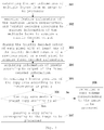
- FIG. 1 A flowchart of a copy area identification method according to an embodiment of the present disclosure is shown in Fig. 1 .
- step 101 feature information of multiple layers is extracted from an image to be processed.
- step 102 the feature of the multiple layers information is encoded respectively, and a jointly decoded output is acquired by jointly decoding according to encoded information of the multiple layers.
- the encoding result or decoding result of each layer may be hybrid decoded during the decoding process to acquire the jointly decoded output.
- step 103 pixel information of pixels are acquired according to the jointly decoded output, wherein the information of the pixels comprises rotation angle information of the copy area, and a distance between each pixel and a border of the copy area.
- the joint decoding is processed by the operation of convolution with a preset depth for acquiring the information of the pixels, and the obtained operation result is regard as the information of the pixels.
- a position of a border of the copy area is determined according to the information of the pixels.
- the position of the border of the copy area may be determined based on a relative position of each pixel to the border of the copy area and a pixel position of each pixel.
- a copy detection algorithm such as Efficient and Accurate Scene Text Detector (EAST)
- EAST Efficient and Accurate Scene Text Detector
- this technology cannot be directly used for copy area detection and font size judgment of advertising images with Chinese; as copy forms in the advertising images are complex and diverse, this technology does not consider copies with complex and various Chinese, and particularly, has a poor effect on longer and shorter copies, and thus, cannot accurately detect copy borders, which will influence the accuracy of copy detection and the accuracy of font size judgment.
- feature information of multiple depths can be acquired through feature extraction, and the feature of each depth is considered simultaneously by means of encoding and joint decoding, and then the border position of the copy area is determined by acquiring and analyzing information of the pixels, thus the speed and accuracy of identifying the copy area in an image can be increased.
- the feature information of the multiple layers from the image to be processed can be extracted by a CNN.
- the CNN is a local connection network and has local connectivity and weight sharing, compared to a full connection network. For a certain pixel in an image, generally, the closer a pixel is to the pixel, the greater the influence on the pixel (local connectivity); in addition, according to statistical features of natural images, a weight of a certain area may also be used on another area (weight sharing) .
- the weight sharing is convolution kernel sharing, and an image feature can be extracted by convolving a convolution kernel with a given image, and a different convolution kernel can extract a different image feature.
- the feature extraction of the image to be processed is performed by a multilayer CNN, and the deeper the network is, the more abstract the feature expression can be extracted.
- a modified Resnet model may be employed as a feature expression of the original input image.
- a hierarchical schematic diagram of the Resnet model may be shown in Fig. 2 .
- FIG. 3 A flowchart of the copy area identification method according to another embodiment of the present disclosure is shown in Fig. 3 .
- step 301 extracting the feature information of the multiply layers is extracted from the image to be processed by a CNN.
- a Resnet-50 model can be adopted for feature extraction, and except a max-pool layer, layers from the second to the fifth are selected for feature analysis.
- the feature information is inputted into a GCN respectively to acquire encoded information of each layer of the multiply layers, and then jointly decoding according to the encoded information of the multiply layers outputted by the GCN.
- the GCN convolves each feature by a 1*k convolution kernel and then by a k*1 convolution kernel to acquire a first code, wherein k is a preset constant; convolves each feature by a k*1 convolution kernel and then by a 1*k convolution kernel to acquire a second code; and sums the first code and the second code, the summed result with a convolution kernel and outputs a convolved result, to acquire the encoded information. Due to the fact that the GCN has a capacity of expanding a perception field, such a method can improve the detection capacity of longer and shorter copies.
- the jointly decoding process may comprise decoding the highest layer feature to acquire the highest layer decoded output; and in a sequence of layers from high to low, jointly decoding by using a decoded output of a upper layer and encoded information of a current layer, and outputting a jointly decoded result to a next layer until the current layer is a lowest layer, and outputting the jointly decoded result.
- that jointly decoding by using the decoded output of the upper layer and the encoded information of the current layer comprises: upsampling the encoded information of the current layer to double the amount of the encoded information, then combining with the decoded output of the upper layer, and convoluting the combined result by a 3*3 convolution kernel and outputting a convoluted result.
- the joint decoding of each pixel can have both high-dimensional and low-dimensional features, and feature contents of the joint decoding are enriched, which improves the accuracy of text area determination.
- step 303 jointly decoded output of each pixel is fused with at least one of the jointly decoded outputs of a previous pixel or a next pixel, to acquire fused decoded information; and acquiring pixel information according to output of the fused decoded information.
- the fused decoded information of each pixel can have features of its previous and next pixels, which is favorable to further improve the accuracy of copy area determination.
- step 304 the fused decoded information is convolved by a 3*3 convolution kernel with a depth of 5, to acquire the distance between each pixel and the border of the copy area in four directions, and the rotation angle information of the copy area.
- step 305 the border position of the border of the copy area is determined by a non-maximum suppression algorithm according to the rotation angle information of the copy area and the distance between the pixel and the copy border in the four directions.
- step 306 the copy area is audited according to a preset copy auditing rule. Under the condition that the copy area meets the preset copy auditing rule, the flow goes to step 307; otherwise, the flow goes to step 308.
- the preset copy auditing rule may comprise a requirement that a font size of the characters on the copy is within a preset range of font sizes.
- the font size of the characters on the copy corresponds to a height or width of a copy (if the copy is arranged horizontally, the font size corresponds to the height of the copy; and if the copy is arranged longitudinally, the font size corresponds to the width of the copy).
- the font size can be determined by the height or width of the copy, and then, compared with a preset interval of copy font sizes; if the copy font size is not within the preset interval of copy font sizes, the font size of the characters on the copy does not meet the requirement.
- the font size of the characters on the copy can be ensured to be within the preset range, which avoids reading difficulty caused by too small font sizes, or bad influence on attractiveness caused by too large font sizes, thus optimizes display effect.
- the preset copy auditing rule may comprise a requirement that the copy area does not occupy a preset protection area, such as an area where an article is displayed in an image, or an area that cannot be occupied according to design and aesthetic requirements; by matching coordinates of the border of the copy area with those of the preset protection area, it is ensured that the copy area does not occupy the preset protection area, to avoid important image information loss caused by copy shielding.
- a preset protection area such as an area where an article is displayed in an image, or an area that cannot be occupied according to design and aesthetic requirements
- Step 307 determining that a copy scheme corresponding to the image to be processed is passed.
- Step 308 rejecting the copy scheme corresponding to the image to be processed.
- the GCN and the recurrent neural network can be added to perform fusion of long text information and refinement of short text information, and thus, the detection accuracy of long and short copy areas in advertising images is improved, auditing manpower is reduced, and the efficiency is increased.
- Fig. 4 shows acquiring pixel information and acquiring a border position of the copy area in the copy area identification method according to an embodiment of the present disclosure.
- step 401 convolving the fused decoded information by a 3*3 convolution kernel with a depth of 1, wherein a result (between 0 and 1) is taken as a probability that a pixel is located in the copy area.
- step 402 convolving the fused decoded information by a 3*3 convolution kernel with a depth of 5 to acquire the rotation angle information of the copy area, and the distance between each pixel and the border of the copy area in four directions.
- step 403 comparing the probability with a preset threshold (e.g., 0.8) according to the probability that the pixel is located in the copy area. If the probability that the pixel is located in the copy area is greater than or equal to the preset threshold, the flow goes to step 405; otherwise, the flow goes to step 404.
- a preset threshold e.g. 0.
- Step 404 discarding pixels whose probability of being located in the copy area is lower than the preset threshold.
- Step 405 determining the border position of the copy area by a non-maximum suppression algorithm according to the rotation angle information of the copy area, and the distance between the pixel and the copy border in the four directions, which improves operation efficiency.
- pixels determined not to belong to the copy area can be filtered away, and then pixels selected are further processed to obtain the border of the copy area, which reduces operation amount and improves processing efficiency.
- FIG. 5 A schematic diagram of a copy area identification device according to an embodiment of the present disclosure is shown in Fig. 5 .
- a feature extraction module 51 can extract feature information of multiple layers from an image to be processed.
- the feature extraction module 51 may be a CNN that extracts multiple features, from concrete to abstract, of the image, to improve the accuracy of the copy area in the image.
- a codec module 52 can encode the feature information of the multiply layers respectively, and jointly decode according to encoded information of the multiple layers to acquire a jointly decoded output.
- the encoding result or decoding result of each layer may be hybrid decoded during the decoding process to acquire the jointly decoded output.
- a pixel information acquisition module 53 can acquire information of pixels according to the jointly decoded output, wherein the information of pixels comprises rotation angle information of the copy area, and a distance between each pixel and a border of the copy area and.
- An area determination module 54 can determine a border position of the border of the copy area according to the information of the pixels.
- the position of the border of the copy area may be determined based on a relative position of each pixel to the border of the copy area and a pixel position of each pixel.
- Such a device can acquire feature information of multiple depths by feature extraction, and consider the feature of each depth simultaneously by means of encoding and joint decoding, and then determine the border position of the copy area by acquiring and analyzing information of the pixels, thus the speed and accuracy of identifying the copy area in an image can be increased.
- the copy area identification device may further comprise an auditing unit 55, capable of auditing the copy area according to a preset copy auditing rule. Under the condition that the copy area meets the preset copy auditing rule, a copy scheme corresponding to the image to be processed is determined to pass; under the condition that the copy area does not meet the preset copy auditing rule, the copy scheme corresponding to the image to be processed is rejected.
- an auditing unit 55 capable of auditing the copy area according to a preset copy auditing rule. Under the condition that the copy area meets the preset copy auditing rule, a copy scheme corresponding to the image to be processed is determined to pass; under the condition that the copy area does not meet the preset copy auditing rule, the copy scheme corresponding to the image to be processed is rejected.
- Such a device can audit the copy area according to the preset copy auditing rule then output an auditing result, which avoids manual operations and improves execution efficiency.
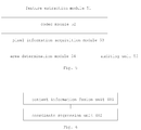
- FIG. 6 A schematic diagram of the pixel information acquisition module in the copy area identification device according to an embodiment of the present disclosure is shown in Fig. 6 .
- the pixel information acquisition module comprise a context information fusion unit 601 and a coordinate regression unit 602.
- the context information fusion unit 601 is capable of fusing the jointly decoded output of each pixel with at least one of the jointly decoded outputs of a previous or next pixel, to acquire fused decoded information.
- the coordinate regression unit 602 is capable of acquiring pixel information according to output of the fused decoded information.
- FIG. 7 A schematic diagram of the codec module in the copy area identification device according to an embodiment of the present disclosure is shown in Fig. 7 .
- the feature information of the multiply layers extracted by the feature extraction module 51 such as features from the second to the fifth layers, are respectively input into the GCNs 2 to 5, and are decoded by decoding units of multiply layers.
- the GCN convolves each feature by a 1*k convolution kernel and then by a k*1 convolution kernel to acquire a first code, wherein k is a preset constant; convolves each feature by a k*1 convolution kernel and then by a 1*k convolution kernel to acquire a second code; and then sums the first code and the second code, the summed result with a convolution kernel and outputs a convolved result, to acquire the encoded information.
- any other decoding unit jointly decodes by using the decoded output of a upper layer and encoded information of a current layer and then outputs to the next layer, and the decoding unit of the lowest layer outputs the jointly decoded information.
- the decoding unit upsamples the encoded information of the current layer to double the amount of the encoded information, stacks with the decoded output of the upper layer, and convolutes a combined result by a 3*3 convolution kernel and outputs the convoluted result, thereby achieving joint decoding by using the decoded output of the upper layer and the encoded information of the current layer.
- Such a device enables the joint decoding of each pixel to have both high-dimensional and low-dimensional features, which enriches feature contents of the joint decoding and improves the accuracy of text area determination.
- the context information fusion unit is used for information fusion processing of the outputs of the codec module.
- a schematic diagram of the context information fusion unit in the copy area identification device according to an embodiment of the present disclosure is shown in Fig. 8 , where the left side is a structure diagram of a Bidirectional Long Short-Term Memory (BLSTM) Network, and the right side is a expansion diagram of a one-way LSTM (Long Short-Term Memory) Network.
- BSSTM Bidirectional Long Short-Term Memory
- each pixel not only has high-dimensional and low-dimensional features, but also has the features of its previous and next pixels.
- the coordinate regression unit 602 convolves the output of the context information fusion unit by a 3*3 convolution kernel (with a depth of 1) to obtain first pixel information, and convolves the output of the context information fusion unit by another parallel 3*3 convolution kernel (with a depth of 5) to obtain second pixel information.
- An amplitude of each point in the first pixel information represents a probability (between 0 and 1) whether the point is located in a text or not.
- the second pixel information comprises 5 channels, and as shown in Fig.
- an amplitude of each pixel represents respectively a distance d_left from this pixel to the left side of the border of the copy which this pixel located in, a distance d_right to the right side thereof, a distance d_up to the top thereof, a distance d_down to the bottom thereof, and a rotation angle theta of the border .
- the area determination module selects pixels with probabilities greater than or equal to a preset threshold according to the probability that each pixel is located in the copy area; and determines the border position of the copy area by a non-maximum suppression algorithm according to the distance between the selected pixels and the copy border in four directions and the rotation angle information of the copy area.
- Such a device can filter away pixels which are determined not to belong to the copy area, and then further processes pixels filtered out to obtain the copy area border, which reduces operation amount and improves processing efficiency.
- Fig. 10 is a schematic structural diagram of the copy area identification device according to an embodiment of the present disclosure.
- the copy area identification device comprises a memory 1001 and a processor 1002, wherein: the memory 1001 may be a magnetic disk, flash memory, or any other non-volatile storage medium.
- the memory is configured to store instructions in the embodiments corresponding to the copy area identification method above.
- the processor 1002, coupled to the memory 1001, may be implemented as one or more integrated circuits, such as a microprocessor or microcontroller.
- the processor 1002 is configured to execute the instructions stored in the memory, to increase the speed and accuracy of identifying the copy area in the image.
- a copy area identification device may also be as shown in Fig. 11 , and the copy area identification device 1100 comprises a memory 1101 and a processor 1102.
- the processor 1102 is coupled to the memory 1101 through a BUS 1103.
- the copy area identification device 1100 may be connected to an external storage device 1105 through a storage interface 1104 to call external data, and also to a network or another computer system (not shown) through a network interface 1106. Detailed descriptions thereof are not repeated herein.
- data instructions are stored in the memory and then processed by the processor, to increase the speed and accuracy of identifying the copy area in the image.
- a computer-readable storage medium has stored thereon computer program instructions which, when executed by a processor, implement the steps of the methods in the embodiments corresponding to the copy area identification method.
- the embodiments of the present disclosure may be provided as a method, device, or computer program product. Accordingly, the present disclosure may take the form of an entirely hardware embodiment, an entirely software embodiment or an embodiment combining software and hardware aspects.
- the present disclosure may take the form of a computer program product embodied on one or more computer-usable non-transitory storage media (including, but not limited to, disk storage, CD-ROM, optical storage, and so forth) having computer-usable program codes embodied therein.
- These computer program instructions may also be stored in a computer-readable memory that can direct the computer or other programmable data processing apparatus to function in a particular manner, such that the instructions stored in this computer-readable memory produce an article of manufacture comprising instruction means which implement the functions specified in one or more flows of the flowcharts and/or one or more blocks of the block diagrams.
- These computer program instructions may also be loaded onto the computer or other programmable data processing apparatus, such that a series of operational steps are performed on the computer or other programmable apparatus to produce a process implemented by the computer, thus the instructions executed on the computer or other programmable apparatus provide the steps for implementing the functions specified in one or more flows of the flowcharts and/or one or more blocks of the block diagrams.
- the methods and apparatus of the present disclosure may be implemented in a number of ways.
- the methods and apparatus of the present disclosure may be implemented by software, hardware, firmware, or any combination of software, hardware, and firmware.
- the above-described order for the steps of the method is for illustration only, and the steps of the method of the present disclosure are not limited to the order specifically described above unless specifically stated otherwise.
- the present disclosure may also be embodied as programs recorded in a recording medium, and these programs comprise machine-readable instructions for implementing the methods according to the present disclosure.
- the present disclosure also covers a recording medium storing the programs for executing the methods according to the present disclosure.
Landscapes
- Engineering & Computer Science (AREA)
- Theoretical Computer Science (AREA)
- Physics & Mathematics (AREA)
- General Physics & Mathematics (AREA)
- Evolutionary Computation (AREA)
- Artificial Intelligence (AREA)
- General Health & Medical Sciences (AREA)
- Health & Medical Sciences (AREA)
- Software Systems (AREA)
- Multimedia (AREA)
- Computing Systems (AREA)
- Computer Vision & Pattern Recognition (AREA)
- Life Sciences & Earth Sciences (AREA)
- Data Mining & Analysis (AREA)
- Molecular Biology (AREA)
- Biomedical Technology (AREA)
- General Engineering & Computer Science (AREA)
- Computational Linguistics (AREA)
- Mathematical Physics (AREA)
- Biophysics (AREA)
- Databases & Information Systems (AREA)
- Medical Informatics (AREA)
- Probability & Statistics with Applications (AREA)
- Biodiversity & Conservation Biology (AREA)
- Quality & Reliability (AREA)
- Bioinformatics & Cheminformatics (AREA)
- Bioinformatics & Computational Biology (AREA)
- Evolutionary Biology (AREA)
- Image Analysis (AREA)
- Image Processing (AREA)
Abstract
Description
- The present application is based on and claims the priority to the Chinese Patent Application No.
201810861942.7, filed on August 1, 2018 - This disclosure relates to the technical field of image processing, and particularly to a copy area identification method and device.
- A large number of commodity advertisements are presented in the form of images inside and outside e-commerce websites every day, and the stock of these advertising images has reached ten billion level with a daily increment of at least several hundred thousand. In order to increase click rates and conversion rates of image advertisements, a platform will make a copy design specification of images, and manually audit them after the images are uploaded by users, which usually costs a large amount of time and manpower.
- According to some embodiments of the present disclosure, there is provided a copy area identification method, comprising: extracting feature information of multiple layers from an image to be processed; encoding the feature of the multiple layers information respectively, and jointly decoding according to encoded information of the multiple layers to acquire a jointly decoded output; acquiring information of pixels according to the jointly decoded output, wherein the information of the pixels comprises rotation angle information of the copy area, and a distance between each of the pixels and a border of the copy area; and determining a position of a border of the copy area according to the information of the pixels.
- In some embodiments, that acquiring pixel information according to the jointly decoded output comprises: acquiring the information of the pixels according to the jointly decoded output comprises: fusing the jointly decoded output of each of the pixels with at least one of the jointly decoded outputs of a previous pixel or a next pixel to acquire fused decoded information; and acquiring the information of the pixels according to output of the fused decoded information
- In some embodiments, the feature information of the multiple layers is extracted by a Convolutional Neural Network (CNN).
- In some embodiments, encoding the feature information extracted respectively comprises: inputting the feature information into a Graph Convolutional Network (GCN) respectively to acquire the encoded information of each layer of the multiple layers.
- In some embodiments, the GCN convolves each feature by a 1*k convolution kernel and then by a k*1 convolution kernel to acquire a first code, wherein k is a preset constant; convolves each of the feature by a k*1 convolution kernel and then by a 1*k convolution kernel to acquire a second code; and sums the first code and the second code, convolves the summed result with a convolution kernel and outputs a convolved result, to acquire the encoded information.
- In some embodiments, jointly decoding according to the encoded information of the multiple layers comprises: decoding the highest layer of the feature information to acquire a highest layer decoded output; and in a sequence of layers from high to low, jointly decoding by using a decoded output of a upper layer and an encoded information of a current layer, and outputting a jointly decoded result to a next layer until the current layer is the lowest layer, then outputting the jointly decoded output.
- In some embodiments, jointly decoding by using the decoded output of the upper layer and the encoded information of the current layer comprises: upsampling the encoded information of the current layer to double the amount of the encoded information, then combining an upsampled result with the decoded output of the upper layer, and then outputting a convolved result after convolving the combined information with a convolve kernel.
- In some embodiments, acquiring the information of the pixels according to the fused decoded information comprises: acquiring the rotation angle information of the copy area, and the distance between each of the pixels and the border of the copy area in four directions by convolving the fused decoded information by a depth of 5; and determining the copy area according to the information of the pixels comprises: determining the position of the border of the copy area by a non-maximum suppression algorithm according to the rotation angle information of the copy area, and the distance between each of the pixels and the border of the copy in the four directions.
- In some embodiments, acquiring the information of the pixels according to the fused decoded information further comprises: convolving the fused decoded information by a depth of 1 to acquire a probability that each of the pixels is located in the copy area; and determining the copy area according to the information of the pixels further comprises: selecting pixels which probabilities are greater than or equal to a preset threshold, according to the probability that each pixel is located in the copy area; and determining the position of the border of the copy area by a non-maximum suppression algorithm is: determining the position of the border of the copy area by the non-maximum suppression algorithm, according to the rotation angle information of the copy area and the distance between the selected pixels and the border of the copy in the four directions.
- In some embodiments, the copy area identification method further comprises: auditing the copy area according to a preset copy auditing rule; and rejecting a copy scheme corresponding to the image to be processed under the condition that the copy area does not meet the preset copy auditing rule.
- In some embodiments, the preset copy auditing rule comprises at least one of: a font size of the characters on the copy being within a preset range of font sizes; or the copy area not occupying a preset protection area.
- According to other embodiments of the present disclosure, there is provided a copy area identification device, comprising: a feature extraction module, configured to extract feature information of multiple layers from an image to be processed; a codec module, configured to encode the feature information of the multiple layers respectively, and jointly decode according to encoded information of the multiple layers to acquire a jointly decoded output; a pixel information acquisition module, configured to acquire information of pixels according to the jointly decoded output, wherein the information of the pixels comprises rotation angle information of the copy area and distances between each of the pixels and borders of the copy area; and an area determination module, configured to determine a position of a border of the copy area according to the information of the pixels.
- In some embodiments, the information of the pixels acquisition module comprises: a context information fusion unit, configured to fuse the jointly decoded output of each of the pixels with at least one of the jointly decoded outputs of a previous pixel or a next pixel, to acquire fused decoded information; and a coordinate regression unit, configured to acquire the information of the pixels according to output of the fused decoded information.
- In some embodiments, the codec module comprises a Graph Convolutional Network (GCN) unit, configured to acquire the encoded information of each layer of the multiple layers according to the feature information.
- In some embodiments, the GCN unit is configured to: the GCN unit is configured to: convolve each feature by a 1*k convolution kernel and then by a k*1 convolution kernel to acquire a first code by, wherein k is a preset constant; convolve each of the feature by a k*1 convolution kernel and then by a 1*k convolution kernel to acquire a second code; and sum the first code and the second code, convolve the summed result with a convolution kernel and output a convolved result, to acquire the encoded information.
- In some embodiments, the codec module comprises a decoding unit, configured to: the codec module comprises a decoding unit, configured to: decode the highest layer of the feature information to acquire the highest layer decoded output; and in a sequence of layers from high to low, jointly decode by using a decoded output of a upper layer and an encoded information of a current layer, and output a jointly decoded result to a next layer until the current layer is the lowest layer, then output the jointly decoded output.
- In some embodiments, the coordinate regression unit is configured to: acquire the rotation angle information of the copy area, and the distance between each of the pixels and the border of the copy area in four directions by convolving the fused decoded information by a depth of 5; and the area determination module is configured to: determine the position of the border of the copy area by a non-maximum suppression algorithm according to the rotation angle information of the copy area and the distance between each of the pixels and the border of the copy in the four directions.
- In some embodiments, the coordinate regression unit is further configured to: convolve the fused decoded information by a depth of 1 to acquire a probability that each of the pixels is located in the copy area; and the area determination module is further configured to: select pixels which probabilities are greater than or equal to a preset threshold according to the probability that each of the pixels is located in the copy area; and determine the border position of the copy area by the non-maximum suppression algorithm, which is: determine the position of the border of the copy area by the non-maximum suppression algorithm, according to the rotation angle information of the copy area , and the distance between the selected pixels and the border of the copy in the four directions.
- In some embodiments, the copy area identification device further comprises an auditing unit configured to: audit the copy area according to a preset copy auditing rule; and reject a copy scheme corresponding to the image to be processed under the condition that the copy area does not meet the preset copy auditing rule.
- According to still other embodiments of the present disclosure, there is provided a copy area identification device, comprising: a memory; and a processor coupled to the memory, wherein the processor is configured to perform any of the copy area identification methods described above based on instructions stored in the memory.
- According to further embodiments of the present disclosure, there is provided a computer-readable storage medium having stored thereon computer program instructions, wherein the instructions, when executed by a processor, implement the steps of any of the copy area identification methods above.
- The accompanying drawings described herein are provided for a further understanding of the present disclosure and constitute a part of this disclosure. The illustrative embodiments of the present disclosure and the descriptions thereof serve to explain but not to improperly limit the present disclosure. In the drawings:
-
Fig. 1 is a flowchart of a copy area identification method according to an embodiment of the present disclosure. -
Fig. 2 is a hierarchical structure diagram of a Residual Network (Resnet) in the copy area identification method according to the present disclosure. -
Fig. 3 is a flowchart of a copy area identification method according to another embodiment of the present disclosure. -
Fig. 4 shows acquiring pixel information and acquiring a border position of the copy area in the copy area identification method according to an embodiment of the present disclosure. -
Fig. 5 is a schematic diagram of a copy area identification device according to an embodiment of the present disclosure. -
Fig. 6 is a schematic diagram of a pixel information acquisition module in the copy area identification device according to an embodiment of the present disclosure. -
Fig. 7 is a schematic diagram of a codec module in the copy area identification device according to an embodiment of the present disclosure. -
Fig. 8 is a schematic diagram of a context information fusion unit in the copy area identification device according to an embodiment of the present disclosure. -
Fig. 9 is a schematic diagram of pixel information acquired by a coordinate regression unit in the copy area identification device according to an embodiment of the present disclosure. -
Fig. 10 is a schematic diagram of a copy area identification device according to another embodiment of the present disclosure. -
Fig. 11 is a schematic diagram of a copy area identification device according to still another embodiment of the present disclosure. - The technical solutions of the present disclosure are further described in detail with reference to the accompanying drawings and embodiments.
- A flowchart of a copy area identification method according to an embodiment of the present disclosure is shown in
Fig. 1 . - In
step 101, feature information of multiple layers is extracted from an image to be processed. - In
step 102, the feature of the multiple layers information is encoded respectively, and a jointly decoded output is acquired by jointly decoding according to encoded information of the multiple layers. In some embodiments, after encoding the feature information of each layer of the multiple layers respectively, the encoding result or decoding result of each layer may be hybrid decoded during the decoding process to acquire the jointly decoded output. - In
step 103, pixel information of pixels are acquired according to the jointly decoded output, wherein the information of the pixels comprises rotation angle information of the copy area, and a distance between each pixel and a border of the copy area. In some embodiments, the joint decoding is processed by the operation of convolution with a preset depth for acquiring the information of the pixels, and the obtained operation result is regard as the information of the pixels. - In
step 104, a position of a border of the copy area is determined according to the information of the pixels. In some embodiments, the position of the border of the copy area may be determined based on a relative position of each pixel to the border of the copy area and a pixel position of each pixel. - In the related art, a copy detection algorithm, such as Efficient and Accurate Scene Text Detector (EAST), has only been tested on some public English data sets to verify the correctness of the algorithm. However, as there are great differences between copies with Chinese and with English in advertising images, this technology cannot be directly used for copy area detection and font size judgment of advertising images with Chinese; as copy forms in the advertising images are complex and diverse, this technology does not consider copies with complex and various Chinese, and particularly, has a poor effect on longer and shorter copies, and thus, cannot accurately detect copy borders, which will influence the accuracy of copy detection and the accuracy of font size judgment.
- With the aid of the embodiment described above, feature information of multiple depths can be acquired through feature extraction, and the feature of each depth is considered simultaneously by means of encoding and joint decoding, and then the border position of the copy area is determined by acquiring and analyzing information of the pixels, thus the speed and accuracy of identifying the copy area in an image can be increased.
- In some embodiments, the feature information of the multiple layers from the image to be processed can be extracted by a CNN. The CNN is a local connection network and has local connectivity and weight sharing, compared to a full connection network. For a certain pixel in an image, generally, the closer a pixel is to the pixel, the greater the influence on the pixel (local connectivity); in addition, according to statistical features of natural images, a weight of a certain area may also be used on another area (weight sharing) . Here, the weight sharing is convolution kernel sharing, and an image feature can be extracted by convolving a convolution kernel with a given image, and a different convolution kernel can extract a different image feature. The feature extraction of the image to be processed is performed by a multilayer CNN, and the deeper the network is, the more abstract the feature expression can be extracted. In some embodiments, a modified Resnet model may be employed as a feature expression of the original input image. A hierarchical schematic diagram of the Resnet model may be shown in
Fig. 2 . By adopting the CNN to perform the multilayer feature extraction, from shallow to deep, of the image to be processed, it enables to extract multiple features, from concrete to abstract, of the image, to improve the accuracy of the copy area in the image. - A flowchart of the copy area identification method according to another embodiment of the present disclosure is shown in
Fig. 3 . - In
step 301, extracting the feature information of the multiply layers is extracted from the image to be processed by a CNN. In some embodiments, in order to achieve both accuracy and operation speed, a Resnet-50 model can be adopted for feature extraction, and except a max-pool layer, layers from the second to the fifth are selected for feature analysis. - In
step 302, the feature information is inputted into a GCN respectively to acquire encoded information of each layer of the multiply layers, and then jointly decoding according to the encoded information of the multiply layers outputted by the GCN. In some embodiments, the GCN convolves each feature by a 1*k convolution kernel and then by a k*1 convolution kernel to acquire a first code, wherein k is a preset constant; convolves each feature by a k*1 convolution kernel and then by a 1*k convolution kernel to acquire a second code; and sums the first code and the second code, the summed result with a convolution kernel and outputs a convolved result, to acquire the encoded information. Due to the fact that the GCN has a capacity of expanding a perception field, such a method can improve the detection capacity of longer and shorter copies. - In some embodiments, the jointly decoding process may comprise decoding the highest layer feature to acquire the highest layer decoded output; and in a sequence of layers from high to low, jointly decoding by using a decoded output of a upper layer and encoded information of a current layer, and outputting a jointly decoded result to a next layer until the current layer is a lowest layer, and outputting the jointly decoded result. In some embodiments, that jointly decoding by using the decoded output of the upper layer and the encoded information of the current layer comprises: upsampling the encoded information of the current layer to double the amount of the encoded information, then combining with the decoded output of the upper layer, and convoluting the combined result by a 3*3 convolution kernel and outputting a convoluted result. By such a method, the joint decoding of each pixel can have both high-dimensional and low-dimensional features, and feature contents of the joint decoding are enriched, which improves the accuracy of text area determination.
- In
step 303, jointly decoded output of each pixel is fused with at least one of the jointly decoded outputs of a previous pixel or a next pixel, to acquire fused decoded information; and acquiring pixel information according to output of the fused decoded information. By such a method, the fused decoded information of each pixel can have features of its previous and next pixels, which is favorable to further improve the accuracy of copy area determination. - In
step 304, the fused decoded information is convolved by a 3*3 convolution kernel with a depth of 5, to acquire the distance between each pixel and the border of the copy area in four directions, and the rotation angle information of the copy area. - In
step 305, the border position of the border of the copy area is determined by a non-maximum suppression algorithm according to the rotation angle information of the copy area and the distance between the pixel and the copy border in the four directions. - In
step 306, the copy area is audited according to a preset copy auditing rule. Under the condition that the copy area meets the preset copy auditing rule, the flow goes to step 307; otherwise, the flow goes to step 308. - In some embodiments, the preset copy auditing rule may comprise a requirement that a font size of the characters on the copy is within a preset range of font sizes. The font size of the characters on the copy corresponds to a height or width of a copy (if the copy is arranged horizontally, the font size corresponds to the height of the copy; and if the copy is arranged longitudinally, the font size corresponds to the width of the copy). the font size can be determined by the height or width of the copy, and then, compared with a preset interval of copy font sizes; if the copy font size is not within the preset interval of copy font sizes, the font size of the characters on the copy does not meet the requirement.
- By such a method, the font size of the characters on the copy can be ensured to be within the preset range, which avoids reading difficulty caused by too small font sizes, or bad influence on attractiveness caused by too large font sizes, thus optimizes display effect.
- In some other embodiments, the preset copy auditing rule may comprise a requirement that the copy area does not occupy a preset protection area, such as an area where an article is displayed in an image, or an area that cannot be occupied according to design and aesthetic requirements; by matching coordinates of the border of the copy area with those of the preset protection area, it is ensured that the copy area does not occupy the preset protection area, to avoid important image information loss caused by copy shielding.
-
Step 307, determining that a copy scheme corresponding to the image to be processed is passed. -
Step 308, rejecting the copy scheme corresponding to the image to be processed. - By such a method, the GCN and the recurrent neural network can be added to perform fusion of long text information and refinement of short text information, and thus, the detection accuracy of long and short copy areas in advertising images is improved, auditing manpower is reduced, and the efficiency is increased.
-
Fig. 4 shows acquiring pixel information and acquiring a border position of the copy area in the copy area identification method according to an embodiment of the present disclosure. - In
step 401, convolving the fused decoded information by a 3*3 convolution kernel with a depth of 1, wherein a result (between 0 and 1) is taken as a probability that a pixel is located in the copy area. - In
step 402, convolving the fused decoded information by a 3*3 convolution kernel with a depth of 5 to acquire the rotation angle information of the copy area, and the distance between each pixel and the border of the copy area in four directions. - In
step 403, comparing the probability with a preset threshold (e.g., 0.8) according to the probability that the pixel is located in the copy area. If the probability that the pixel is located in the copy area is greater than or equal to the preset threshold, the flow goes to step 405; otherwise, the flow goes to step 404. -
Step 404, discarding pixels whose probability of being located in the copy area is lower than the preset threshold. -
Step 405, determining the border position of the copy area by a non-maximum suppression algorithm according to the rotation angle information of the copy area, and the distance between the pixel and the copy border in the four directions, which improves operation efficiency. - By such a method, pixels determined not to belong to the copy area can be filtered away, and then pixels selected are further processed to obtain the border of the copy area, which reduces operation amount and improves processing efficiency.
- A schematic diagram of a copy area identification device according to an embodiment of the present disclosure is shown in
Fig. 5 . - A
feature extraction module 51 can extract feature information of multiple layers from an image to be processed. In some embodiments, thefeature extraction module 51 may be a CNN that extracts multiple features, from concrete to abstract, of the image, to improve the accuracy of the copy area in the image. - A
codec module 52 can encode the feature information of the multiply layers respectively, and jointly decode according to encoded information of the multiple layers to acquire a jointly decoded output. In some embodiments, after encoding the feature information of each layer of the multiple layers respectively, the encoding result or decoding result of each layer may be hybrid decoded during the decoding process to acquire the jointly decoded output. - A pixel
information acquisition module 53 can acquire information of pixels according to the jointly decoded output, wherein the information of pixels comprises rotation angle information of the copy area, and a distance between each pixel and a border of the copy area and. - An
area determination module 54 can determine a border position of the border of the copy area according to the information of the pixels. In some embodiments, the position of the border of the copy area may be determined based on a relative position of each pixel to the border of the copy area and a pixel position of each pixel. - Such a device can acquire feature information of multiple depths by feature extraction, and consider the feature of each depth simultaneously by means of encoding and joint decoding, and then determine the border position of the copy area by acquiring and analyzing information of the pixels, thus the speed and accuracy of identifying the copy area in an image can be increased.
- In some embodiments, the copy area identification device may further comprise an
auditing unit 55, capable of auditing the copy area according to a preset copy auditing rule. Under the condition that the copy area meets the preset copy auditing rule, a copy scheme corresponding to the image to be processed is determined to pass; under the condition that the copy area does not meet the preset copy auditing rule, the copy scheme corresponding to the image to be processed is rejected. - Such a device can audit the copy area according to the preset copy auditing rule then output an auditing result, which avoids manual operations and improves execution efficiency.
- A schematic diagram of the pixel information acquisition module in the copy area identification device according to an embodiment of the present disclosure is shown in
Fig. 6 . The pixel information acquisition module comprise a context information fusion unit 601 and a coordinateregression unit 602. - The context information fusion unit 601 is capable of fusing the jointly decoded output of each pixel with at least one of the jointly decoded outputs of a previous or next pixel, to acquire fused decoded information. The coordinate
regression unit 602 is capable of acquiring pixel information according to output of the fused decoded information. By using such a device to process the image, the fused decoded information of each pixel can have the features of both its previous and next pixels, which is favorable to further improve the accuracy of copy area determination. - A schematic diagram of the codec module in the copy area identification device according to an embodiment of the present disclosure is shown in
Fig. 7 . The feature information of the multiply layers extracted by thefeature extraction module 51, such as features from the second to the fifth layers, are respectively input into the GCNs 2 to 5, and are decoded by decoding units of multiply layers. In some embodiments, the GCN convolves each feature by a 1*k convolution kernel and then by a k*1 convolution kernel to acquire a first code, wherein k is a preset constant; convolves each feature by a k*1 convolution kernel and then by a 1*k convolution kernel to acquire a second code; and then sums the first code and the second code, the summed result with a convolution kernel and outputs a convolved result, to acquire the encoded information. - In some embodiments, as shown in
Fig. 7 , except the decoding unit for decoding the encoding of the highest layer, any other decoding unit jointly decodes by using the decoded output of a upper layer and encoded information of a current layer and then outputs to the next layer, and the decoding unit of the lowest layer outputs the jointly decoded information. In some embodiments, the decoding unit upsamples the encoded information of the current layer to double the amount of the encoded information, stacks with the decoded output of the upper layer, and convolutes a combined result by a 3*3 convolution kernel and outputs the convoluted result, thereby achieving joint decoding by using the decoded output of the upper layer and the encoded information of the current layer. - Such a device enables the joint decoding of each pixel to have both high-dimensional and low-dimensional features, which enriches feature contents of the joint decoding and improves the accuracy of text area determination.
- In view of the problem that an accurate border of a long copy cannot be acquired because various propaganda copies in advertising images change greatly and lengths of some copies may exceed the range of a neural network perception field, the context information fusion unit is used for information fusion processing of the outputs of the codec module. A schematic diagram of the context information fusion unit in the copy area identification device according to an embodiment of the present disclosure is shown in
Fig. 8 , where the left side is a structure diagram of a Bidirectional Long Short-Term Memory (BLSTM) Network, and the right side is a expansion diagram of a one-way LSTM (Long Short-Term Memory) Network. The features with a dimension of C (C represents the number of channels, and C is a positive integer) corresponding to all windows of each row output by the codec module are input into a bidirectional Recurrent Neural Network (RNN) (BLSTM) to obtain a 256-dimensional (the number of hidden layers of RNN) output, and then the feature size is changed back to C through a full connection layer. After processed by the recursive neural network, each pixel not only has high-dimensional and low-dimensional features, but also has the features of its previous and next pixels. Such a device can optimize the accuracy of the acquired border information when processing longer copy information. - In some embodiments, the coordinate
regression unit 602 convolves the output of the context information fusion unit by a 3*3 convolution kernel (with a depth of 1) to obtain first pixel information, and convolves the output of the context information fusion unit by another parallel 3*3 convolution kernel (with a depth of 5) to obtain second pixel information. An amplitude of each point in the first pixel information represents a probability (between 0 and 1) whether the point is located in a text or not. The second pixel information comprises 5 channels, and as shown inFig. 9 , an amplitude of each pixel represents respectively a distance d_left from this pixel to the left side of the border of the copy which this pixel located in, a distance d_right to the right side thereof, a distance d_up to the top thereof, a distance d_down to the bottom thereof, and a rotation angle theta of the border . - The area determination module selects pixels with probabilities greater than or equal to a preset threshold according to the probability that each pixel is located in the copy area; and determines the border position of the copy area by a non-maximum suppression algorithm according to the distance between the selected pixels and the copy border in four directions and the rotation angle information of the copy area.
- Such a device can filter away pixels which are determined not to belong to the copy area, and then further processes pixels filtered out to obtain the copy area border, which reduces operation amount and improves processing efficiency.
-
Fig. 10 is a schematic structural diagram of the copy area identification device according to an embodiment of the present disclosure. The copy area identification device comprises amemory 1001 and aprocessor 1002, wherein: thememory 1001 may be a magnetic disk, flash memory, or any other non-volatile storage medium. The memory is configured to store instructions in the embodiments corresponding to the copy area identification method above. Theprocessor 1002, coupled to thememory 1001, may be implemented as one or more integrated circuits, such as a microprocessor or microcontroller. Theprocessor 1002 is configured to execute the instructions stored in the memory, to increase the speed and accuracy of identifying the copy area in the image. - In some embodiments, a copy area identification device may also be as shown in
Fig. 11 , and the copyarea identification device 1100 comprises amemory 1101 and aprocessor 1102. Theprocessor 1102 is coupled to thememory 1101 through aBUS 1103. The copyarea identification device 1100 may be connected to anexternal storage device 1105 through astorage interface 1104 to call external data, and also to a network or another computer system (not shown) through anetwork interface 1106. Detailed descriptions thereof are not repeated herein. - In this embodiment, data instructions are stored in the memory and then processed by the processor, to increase the speed and accuracy of identifying the copy area in the image.
- In another embodiment, a computer-readable storage medium has stored thereon computer program instructions which, when executed by a processor, implement the steps of the methods in the embodiments corresponding to the copy area identification method. As will be appreciated by one skilled in the art, the embodiments of the present disclosure may be provided as a method, device, or computer program product. Accordingly, the present disclosure may take the form of an entirely hardware embodiment, an entirely software embodiment or an embodiment combining software and hardware aspects. Furthermore, the present disclosure may take the form of a computer program product embodied on one or more computer-usable non-transitory storage media (including, but not limited to, disk storage, CD-ROM, optical storage, and so forth) having computer-usable program codes embodied therein.
- The present disclosure is described with reference to flowcharts and/or block diagrams of methods, apparatus (systems) and computer program products according to the embodiments of the present disclosure. It will be understood that each flow and/or block of the flowcharts and/or block diagrams, and combinations of flows and/or blocks in the flowcharts and/or block diagrams, can be implemented by computer program instructions. These computer program instructions may be provided to a processor of a general purpose computer, special purpose computer, embedded processor, or other programmable data processing apparatus to produce a machine, such that by the instructions executed by the processor of the computer or other programmable data processing apparatus, means for implementing the functions specified in one or more flows of the flowcharts and/or one or more blocks of the block diagrams are created.
- These computer program instructions may also be stored in a computer-readable memory that can direct the computer or other programmable data processing apparatus to function in a particular manner, such that the instructions stored in this computer-readable memory produce an article of manufacture comprising instruction means which implement the functions specified in one or more flows of the flowcharts and/or one or more blocks of the block diagrams.
- These computer program instructions may also be loaded onto the computer or other programmable data processing apparatus, such that a series of operational steps are performed on the computer or other programmable apparatus to produce a process implemented by the computer, thus the instructions executed on the computer or other programmable apparatus provide the steps for implementing the functions specified in one or more flows of the flowcharts and/or one or more blocks of the block diagrams.
- Thus far, the present disclosure has been described in detail. Some details well known in the art have not been described in order to avoid obscuring the concepts of the present disclosure. Those skilled in the art can now fully appreciate how to implement the technical solution disclosed herein, in view of the foregoing description.
- The methods and apparatus of the present disclosure may be implemented in a number of ways. For example, the methods and apparatus of the present disclosure may be implemented by software, hardware, firmware, or any combination of software, hardware, and firmware. The above-described order for the steps of the method is for illustration only, and the steps of the method of the present disclosure are not limited to the order specifically described above unless specifically stated otherwise. Further, in some embodiments, the present disclosure may also be embodied as programs recorded in a recording medium, and these programs comprise machine-readable instructions for implementing the methods according to the present disclosure. Thus, the present disclosure also covers a recording medium storing the programs for executing the methods according to the present disclosure.
- Finally, it should be noted that: the above embodiments are intended only to illustrate the technical solutions of the present disclosure but not to limit them; although the present disclosure has been described in detail with reference to the preferred embodiments, those of ordinary skill in the art will understand that: modifications to the specific embodiments of the present disclosure or equivalent substitutions for parts of the technical features may be made, all of which are intended to be covered by the scope of the technical solutions as claimed in this disclosure without departing from the spirit thereof.
Claims (21)
- A copy area identification method, comprising:extracting feature information of multiple layers from an image to be processed;encoding the feature of the multiple layers information respectively, and jointly decoding according to encoded information of the multiple layers to acquire a jointly decoded output;acquiring information of pixels according to the jointly decoded output, wherein the information of the pixels comprises rotation angle information of the copy area, and a distance between each of the pixels and a border of the copy area; anddetermining a position of a border of the copy area according to the information of the pixels.
- The copy area identification method according to claim 1, wherein acquiring the information of the pixels according to the jointly decoded output comprises:fusing the jointly decoded output of each of the pixels with at least one of the jointly decoded outputs of a previous pixel or a next pixel to acquire fused decoded information; andacquiring the information of the pixels according to output of the fused decoded information.
- The copy area identification method according to claim 1, wherein, the feature information of the multiple layers is extracted by a Convolutional Neural Network (CNN).
- The copy area identification method according to claim 1, wherein encoding the feature information extracted respectively comprises:
inputting the feature information into a Graph Convolutional Network (GCN) respectively to acquire the encoded information of each layer of the multiple layers. - The copy area identification method according to claim 4, wherein
the GCN convolves each feature by a 1*k convolution kernel and then by a k*1 convolution kernel to acquire a first code, wherein k is a preset constant;
convolves each of the feature by a k*1 convolution kernel and then by a 1*k convolution kernel to acquire a second code; and
sums the first code and the second code, convolves the summed result with a convolution kernel and outputs a convolved result, to acquire the encoded information. - The copy area identification method according to claim 1, wherein jointly decoding according to the encoded information of the multiple layers comprises:decoding the highest layer of the feature information to acquire a highest layer decoded output; andin a sequence of layers from high to low, jointly decoding by using a decoded output of a upper layer and an encoded information of a current layer, and outputting a jointly decoded result to a next layer until the current layer is the lowest layer, then outputting the jointly decoded result.
- The copy area identification method according to claim 6, wherein jointly decoding by using the decoded output of the upper layer and the encoded information of the current layer comprises:
upsampling the encoded information of the current layer to double the amount of the encoded information, then combining an upsampled result with the decoded output of the upper layer, and then outputting a convolved result after convolving the combined information with a convolve kernel. - The copy area identification method according to claim 2, wherein acquiring the information of the pixels according to the fused decoded information comprises:acquiring the rotation angle information of the copy area, and the distance between each of the pixels and the border of the copy area in four directions by convolving the fused decoded information by a depth of 5; anddetermining the copy area according to the information of the pixels comprises:
determining the position of the border of the copy area by a non-maximum suppression algorithm according to the rotation angle information of the copy area, and the distance between each of the pixels and the border of the copy in the four directions. - The copy area identification method according to claim 8, wherein acquiring the information of the pixels according to the fused decoded information further comprises:convolving the fused decoded information by a depth of 1 to acquire a probability that each of the pixels is located in the copy area; anddetermining the copy area according to the information of the pixels further comprises:selecting pixels which probabilities are greater than or equal to a preset threshold, according to the probability that each pixel is located in the copy area; anddetermining the position of the border of the copy area by a non-maximum suppression algorithm is: determining the position of the border of the copy area by the non-maximum suppression algorithm, according to the rotation angle information of the copy area and the distance between the selected pixels and the border of the copy in the four directions .
- The copy area identification method according to claim 1, further comprising:auditing the copy area according to a preset copy auditing rule; andrejecting a copy scheme corresponding to the image to be processed under the condition that the copy area does not meet the preset copy auditing rule.
- The copy area identification method according to claim 10, wherein the preset copy auditing rule comprises at least one of:a font size of the characters on the copy being within a preset range of font sizes; orthe copy area not occupying a preset protection area.
- A copy area identification device, comprising:a feature extraction module, configured to extract feature information of multiple layers from an image to be processed;a codec module, configured to encode the feature information of the multiple layers respectively, and jointly decode according to encoded information of the multiple layers to acquire a jointly decoded output;a pixel information acquisition module, configured to acquire information of pixels according to the jointly decoded output, wherein the information of the pixels comprises rotation angle information of the copy area and distances between each of the pixels and borders of the copy area; andan area determination module, configured to determine a position of a border of the copy area according to the information of the pixels.
- The copy area identification device according to claim 12, wherein the information of the pixels acquisition module comprises:a context information fusion unit, configured to fuse the jointly decoded output of each of the pixels with at least one of the jointly decoded outputs of a previous pixel or a next pixel, to acquire fused decoded information; anda coordinate regression unit, configured to acquire the information of the pixels according to output of the fused decoded information.
- The copy area identification device according to claim 12, wherein, the codec module comprises a Graph Convolutional Network (GCN) unit, configured to acquire the encoded information of each layer of the multiple layers according to the feature information.
- The copy area identification device according to claim 14, wherein the GCN unit is configured to: convolve each feature by a 1*k convolution kernel and then by a k*1 convolution kernel to acquire a first code by, wherein k is a preset constant;
convolve each of the feature by a k*1 convolution kernel and then by a 1*k convolution kernel to acquire a second code; and
sum the first code and the second code, convolve the summed result with a convolution kernel and output a convolved result, to acquire the encoded information. - The copy area identification device according to claim 12, wherein the codec module comprises a decoding unit, configured to:decode the highest layer of the feature information to acquire the highest layer decoded output; andin a sequence of layers from high to low, jointly decode by using a decoded output of a upper layer and an encoded information of a current layer, and output a jointly decoded result to a next layer until the current layer is the lowest layer, then output the jointly decoded output.
- The copy area identification device according to claim 13, wherein,
the coordinate regression unit is configured to:acquire the rotation angle information of the copy area, and the distance between each of the pixels and the border of the copy area in four directions by convolving the fused decoded information by a depth of 5; andthe area determination module is configured to:
determine the position of the border of the copy area by a non-maximum suppression algorithm according to the rotation angle information of the copy area and the distance between each of the pixels and the border of the copy in the four directions. - The copy area identification device according to claim 17, wherein the coordinate regression unit is further configured to:convolve the fused decoded information by a depth of 1 to acquire a probability that each of the pixels is located in the copy area; andthe area determination module is further configured to:select pixels which probabilities are greater than or equal to a preset threshold according to the probability that each of the pixels is located in the copy area; anddetermine the border position of the copy area by the non-maximum suppression algorithm, which is: determine the position of the border of the copy area by the non-maximum suppression algorithm, according to the rotation angle information of the copy area , and the distance between the selected pixels and the border of the copy in the four directions.
- The copy area identification device according to claim 12, further comprising an auditing unit configured to:audit the copy area according to a preset copy auditing rule; andreject a copy scheme corresponding to the image to be processed under the condition that the copy area does not meet the preset copy auditing rule.
- A copy area identification device, comprising:a memory; anda processor coupled to the memory, wherein the processor is configured to perform the copy area identification method according to any of claims 1 to 11 based on instructions stored in the memory.
- A computer-readable storage medium having stored thereon computer program instructions, wherein the instructions, when executed by a processor, implement the steps of the copy area identification method according to any of claims 1 to 11.
Applications Claiming Priority (2)
| Application Number | Priority Date | Filing Date | Title |
|---|---|---|---|
| CN201810861942.7A CN110796133B (en) | 2018-08-01 | 2018-08-01 | Copy area recognition method and device |
| PCT/CN2019/098414 WO2020024939A1 (en) | 2018-08-01 | 2019-07-30 | Text region identification method and device |
Publications (2)
| Publication Number | Publication Date |
|---|---|
| EP3812965A1 true EP3812965A1 (en) | 2021-04-28 |
| EP3812965A4 EP3812965A4 (en) | 2022-03-30 |
Family
ID=69231441
Family Applications (1)
| Application Number | Title | Priority Date | Filing Date |
|---|---|---|---|
| EP19845554.5A Pending EP3812965A4 (en) | 2018-08-01 | 2019-07-30 | TEXT ZONE IDENTIFICATION METHOD AND DEVICE |
Country Status (4)
| Country | Link |
|---|---|
| US (1) | US11763167B2 (en) |
| EP (1) | EP3812965A4 (en) |
| CN (1) | CN110796133B (en) |
| WO (1) | WO2020024939A1 (en) |
Cited By (2)
| Publication number | Priority date | Publication date | Assignee | Title |
|---|---|---|---|---|
| CN115575857A (en) * | 2022-12-08 | 2023-01-06 | 江西广凯新能源股份有限公司 | Emergency protection method and device for high-voltage wire breakage |
| US20230049296A1 (en) * | 2019-02-11 | 2023-02-16 | Open Text Sa Ulc | On-device artificial intelligence systems and methods for document auto-rotation |
Families Citing this family (5)
| Publication number | Priority date | Publication date | Assignee | Title |
|---|---|---|---|---|
| CN111950356B (en) * | 2020-06-30 | 2024-04-19 | 深圳市雄帝科技股份有限公司 | Seal text positioning method and device and electronic equipment |
| CN112101165B (en) * | 2020-09-07 | 2022-07-15 | 腾讯科技(深圳)有限公司 | Point of interest identification method, apparatus, computer equipment and storage medium |
| CN113453012B (en) * | 2021-06-25 | 2023-02-28 | 杭州海康威视数字技术股份有限公司 | Codec method, device and electronic equipment |
| CN113887535B (en) * | 2021-12-03 | 2022-04-12 | 北京世纪好未来教育科技有限公司 | Model training method, text recognition method, apparatus, equipment and medium |
| CN114283436A (en) * | 2021-12-20 | 2022-04-05 | 万翼科技有限公司 | Table identification method, device, equipment and storage medium |
Family Cites Families (19)
| Publication number | Priority date | Publication date | Assignee | Title |
|---|---|---|---|---|
| US6532302B2 (en) * | 1998-04-08 | 2003-03-11 | Canon Kabushiki Kaisha | Multiple size reductions for image segmentation |
| EP1831823B1 (en) * | 2004-12-21 | 2011-03-09 | Canon Kabushiki Kaisha | Segmenting digital image and producing compact representation |
| US20080310721A1 (en) * | 2007-06-14 | 2008-12-18 | John Jinhwan Yang | Method And Apparatus For Recognizing Characters In A Document Image |
| US8462394B2 (en) * | 2008-08-05 | 2013-06-11 | Xerox Corporation | Document type classification for scanned bitmaps |
| US20150200998A1 (en) * | 2012-01-30 | 2015-07-16 | Google Inc. | Displaying portions of a host display area of a host device at a client device |
| US9424767B2 (en) * | 2012-06-18 | 2016-08-23 | Microsoft Technology Licensing, Llc | Local rendering of text in image |
| US9628865B2 (en) * | 2012-09-10 | 2017-04-18 | Apple Inc. | Enhanced closed caption feature |
| CN103002288B (en) * | 2012-12-28 | 2015-10-21 | 北京视博云科技有限公司 | A kind of decoding method of video image and device |
| CN103686181B (en) * | 2013-12-13 | 2017-01-18 | 北京东方正龙数字技术有限公司 | Method and system for coding screen display information |
| CN107391505B (en) * | 2016-05-16 | 2020-10-23 | 腾讯科技(深圳)有限公司 | Image processing method and system |
| CN106778867B (en) * | 2016-12-15 | 2020-07-07 | 北京旷视科技有限公司 | Target detection method and device, neural network training method and device |
| CN106960206B (en) * | 2017-02-08 | 2021-01-01 | 北京捷通华声科技股份有限公司 | Character recognition method and character recognition system |
| CN107247950A (en) * | 2017-06-06 | 2017-10-13 | 电子科技大学 | A kind of ID Card Image text recognition method based on machine learning |
| CN107527059B (en) * | 2017-08-07 | 2021-12-21 | 北京小米移动软件有限公司 | Character recognition method and device and terminal |
| CN107820096B (en) | 2017-11-09 | 2019-12-03 | 京东方科技集团股份有限公司 | Image processing device and method, image processing system and training method |
| CN108229303B (en) * | 2017-11-14 | 2021-05-04 | 北京市商汤科技开发有限公司 | Detection and recognition and detection and recognition network training method and device, equipment, medium |
| CN108171010B (en) * | 2017-12-01 | 2021-09-14 | 华南师范大学 | Protein complex detection method and device based on semi-supervised network embedded model |
| CN108230329B (en) * | 2017-12-18 | 2021-09-21 | 孙颖 | Semantic segmentation method based on multi-scale convolution neural network |
| US10248664B1 (en) * | 2018-07-02 | 2019-04-02 | Inception Institute Of Artificial Intelligence | Zero-shot sketch-based image retrieval techniques using neural networks for sketch-image recognition and retrieval |
-
2018
- 2018-08-01 CN CN201810861942.7A patent/CN110796133B/en active Active
-
2019
- 2019-07-30 WO PCT/CN2019/098414 patent/WO2020024939A1/en not_active Ceased
- 2019-07-30 EP EP19845554.5A patent/EP3812965A4/en active Pending
-
2021
- 2021-01-22 US US17/155,168 patent/US11763167B2/en active Active
Cited By (6)
| Publication number | Priority date | Publication date | Assignee | Title |
|---|---|---|---|---|
| US20230049296A1 (en) * | 2019-02-11 | 2023-02-16 | Open Text Sa Ulc | On-device artificial intelligence systems and methods for document auto-rotation |
| US11847563B2 (en) * | 2019-02-11 | 2023-12-19 | Open Text Sa Ulc | On-device artificial intelligence systems and methods for document auto-rotation |
| US20240070462A1 (en) * | 2019-02-11 | 2024-02-29 | Open Text Sa Ulc | On-device artificial intelligence systems and methods for document auto-rotation |
| US12307369B2 (en) * | 2019-02-11 | 2025-05-20 | Crowdstrike, Inc. | On-device artificial intelligence systems and methods for document auto-rotation |
| CN115575857A (en) * | 2022-12-08 | 2023-01-06 | 江西广凯新能源股份有限公司 | Emergency protection method and device for high-voltage wire breakage |
| CN115575857B (en) * | 2022-12-08 | 2023-04-28 | 江西广凯新能源股份有限公司 | Emergency protection method and device for high-voltage wire breakage |
Also Published As
| Publication number | Publication date |
|---|---|
| CN110796133B (en) | 2024-05-24 |
| US20210142513A1 (en) | 2021-05-13 |
| EP3812965A4 (en) | 2022-03-30 |
| US11763167B2 (en) | 2023-09-19 |
| CN110796133A (en) | 2020-02-14 |
| WO2020024939A1 (en) | 2020-02-06 |
Similar Documents
| Publication | Publication Date | Title |
|---|---|---|
| US11763167B2 (en) | Copy area identification method and device | |
| CN109933756B (en) | Image file transferring method, device and equipment based on OCR (optical character recognition), and readable storage medium | |
| CN111369581B (en) | Image processing method, device, equipment and storage medium | |
| Chen et al. | EM-trans: Edge-aware multimodal transformer for RGB-D salient object detection | |
| Wang et al. | Stereoscopic inpainting: Joint color and depth completion from stereo images | |
| CN104217202B (en) | Information identification method, equipment and system | |
| CN110084172B (en) | Character recognition method and device and electronic equipment | |
| US12020400B2 (en) | Upsampling and refining segmentation masks | |
| CN111914654B (en) | Text layout analysis method, device, equipment and medium | |
| CN114612832A (en) | Real-time gesture detection method and device | |
| CN114529773B (en) | Table recognition method, system, terminal and medium based on structural unit | |
| CN114463187B (en) | Image semantic segmentation method and system based on aggregation edge features | |
| CN116092105B (en) | Method and device for analyzing table structure | |
| CN114638814A (en) | Method, system, medium and device for automatically staging colorectal cancer based on CT (computed tomography) image | |
| CN116994000B (en) | Methods and apparatus for extracting edge features of parts, electronic equipment and storage media | |
| CN111862343A (en) | Three-dimensional reconstruction method, device and equipment and computer readable storage medium | |
| CN114820666B (en) | Method and device for increasing matting accuracy, computer equipment and storage medium | |
| CN110533020B (en) | Method, device and storage medium for identifying text information | |
| CN113033531B (en) | A method, device and electronic equipment for text recognition in images | |
| WO2025043445A1 (en) | Depth map optimization model training method and apparatus, and device and storage medium | |
| CN116977336A (en) | Camera defect detection method, device, computer equipment and storage medium | |
| CN112052863B (en) | Image detection method and device, computer storage medium and electronic equipment | |
| CN112801046B (en) | Image processing method, apparatus, electronic device and computer storage medium | |
| CN115546810B (en) | Image element category identification method and device | |
| US20260134545A1 (en) | Generating multiple segmentation masks in a single model with multi-task query decoders |
Legal Events
| Date | Code | Title | Description |
|---|---|---|---|
| STAA | Information on the status of an ep patent application or granted ep patent |
Free format text: STATUS: THE INTERNATIONAL PUBLICATION HAS BEEN MADE |
|
| PUAI | Public reference made under article 153(3) epc to a published international application that has entered the european phase |
Free format text: ORIGINAL CODE: 0009012 |
|
| STAA | Information on the status of an ep patent application or granted ep patent |
Free format text: STATUS: REQUEST FOR EXAMINATION WAS MADE |
|
| 17P | Request for examination filed |
Effective date: 20210122 |
|
| AK | Designated contracting states |
Kind code of ref document: A1 Designated state(s): AL AT BE BG CH CY CZ DE DK EE ES FI FR GB GR HR HU IE IS IT LI LT LU LV MC MK MT NL NO PL PT RO RS SE SI SK SM TR |
|
| AX | Request for extension of the european patent |
Extension state: BA ME |
|
| DAV | Request for validation of the european patent (deleted) | ||
| DAX | Request for extension of the european patent (deleted) | ||
| REG | Reference to a national code |
Ref country code: DE Ref legal event code: R079 Free format text: PREVIOUS MAIN CLASS: G06K0009200000 Ipc: G06V0010820000 |
|
| A4 | Supplementary search report drawn up and despatched |
Effective date: 20220301 |
|
| RIC1 | Information provided on ipc code assigned before grant |
Ipc: G06V 10/44 20220101ALI20220223BHEP Ipc: G06V 10/84 20220101ALI20220223BHEP Ipc: G06V 10/82 20220101AFI20220223BHEP |
|
| STAA | Information on the status of an ep patent application or granted ep patent |
Free format text: STATUS: EXAMINATION IS IN PROGRESS |
|
| 17Q | First examination report despatched |
Effective date: 20240425 |
|
| REG | Reference to a national code |
Ref country code: DE Ref legal event code: R079 Free format text: PREVIOUS MAIN CLASS: G06V0010820000 Ipc: G06N0003088000 |
|
| GRAP | Despatch of communication of intention to grant a patent |
Free format text: ORIGINAL CODE: EPIDOSNIGR1 |
|
| STAA | Information on the status of an ep patent application or granted ep patent |
Free format text: STATUS: GRANT OF PATENT IS INTENDED |
|
| RIC1 | Information provided on ipc code assigned before grant |
Ipc: G06N 3/088 20230101AFI20260329BHEP Ipc: G06V 10/25 20220101ALI20260329BHEP Ipc: G06V 10/82 20220101ALI20260329BHEP Ipc: G06V 30/19 20220101ALI20260329BHEP Ipc: G06V 10/84 20220101ALI20260329BHEP Ipc: G06V 10/44 20220101ALI20260329BHEP Ipc: G06N 3/045 20230101ALI20260329BHEP Ipc: G06N 3/044 20230101ALI20260329BHEP Ipc: G06N 3/0442 20230101ALI20260329BHEP Ipc: G06N 3/0455 20230101ALI20260329BHEP Ipc: G06N 3/0464 20230101ALI20260329BHEP |
|
| INTG | Intention to grant announced |
Effective date: 20260414 |