EP3812912A1 - Method of synchronizing a receiver of a synchronous serial communication system for a receiving process of a data frame of a predefined frame size from the synchronous serial communication system, receiver, transmitter and system - Google Patents
Method of synchronizing a receiver of a synchronous serial communication system for a receiving process of a data frame of a predefined frame size from the synchronous serial communication system, receiver, transmitter and system Download PDFInfo
- Publication number
- EP3812912A1 EP3812912A1 EP19465581.7A EP19465581A EP3812912A1 EP 3812912 A1 EP3812912 A1 EP 3812912A1 EP 19465581 A EP19465581 A EP 19465581A EP 3812912 A1 EP3812912 A1 EP 3812912A1
- Authority
- EP
- European Patent Office
- Prior art keywords
- receiver
- communication system
- serial communication
- synchronous serial
- reception
- Prior art date
- Legal status (The legal status is an assumption and is not a legal conclusion. Google has not performed a legal analysis and makes no representation as to the accuracy of the status listed.)
- Granted
Links
Images

Classifications
-
- G—PHYSICS
- G06—COMPUTING OR CALCULATING; COUNTING
- G06F—ELECTRIC DIGITAL DATA PROCESSING
- G06F13/00—Interconnection of, or transfer of information or other signals between, memories, input/output devices or central processing units
- G06F13/38—Information transfer, e.g. on bus
- G06F13/42—Bus transfer protocol, e.g. handshake; Synchronisation
- G06F13/4282—Bus transfer protocol, e.g. handshake; Synchronisation on a serial bus, e.g. I2C bus, SPI bus
- G06F13/4291—Bus transfer protocol, e.g. handshake; Synchronisation on a serial bus, e.g. I2C bus, SPI bus using a clocked protocol
-
- G—PHYSICS
- G06—COMPUTING OR CALCULATING; COUNTING
- G06F—ELECTRIC DIGITAL DATA PROCESSING
- G06F13/00—Interconnection of, or transfer of information or other signals between, memories, input/output devices or central processing units
- G06F13/38—Information transfer, e.g. on bus
- G06F13/382—Information transfer, e.g. on bus using universal interface adapter
- G06F13/385—Information transfer, e.g. on bus using universal interface adapter for adaptation of a particular data processing system to different peripheral devices
Definitions
- the invention is concerned with a method of synchronising a receiver of a synchronous serial communication system for a receiving process of a data frame of a predefined frame size from the synchronous serial communication system, a receiver, a transmitter and a system comprising at least one receiver and at least one transmitter.
- data are arranged in data frames or packages. These data frames are sent via a connection between the sender and the receiver. To ensure the transmission between the sender and the receiver, it is necessary, that the receiver identifies the data frame in the data stream of the connection. This process of identification is called frame synchronization.
- Sync words are predefined characters at the beginning of a respective data frame.
- Symbol-level synchronization in Universal Asynchronous Receiver Transmitter (UART) is based on predefined bits at the start and at the end of a respective data frame.
- Serial Peripheral Interface (SPI) frame synchronisation is performed by using chip selection which uses a special line of the SPI bus system.
- Serial Peripheral Interface Bus systems comprise at least one SPI master device and at least one SPI slave device.
- the master device provides a clock signal on one wire of the SPI interface.
- the clock signal is used for synchronisation between the devices of the Serial Peripheral Interface Bus system.
- the master sends the clock signal and selects the slave by a specific chip select signal.
- US 2012/0140673 A1 disclosures an Inter-frame gap controller, traffic transmitter, transmission apparatus and an inter-frame gap control method.
- the inter-frame gap controller comprises an inter-frame gap length determiner that determines a length of an inter-frame gap based on traffic volume of Ethernet frames which are converted to synchronous frames and are transmitted over a synchronous network.
- the inter-frame gap controller comprises a gap inserter that inserts an inter-frame gap of length determined by said inter-frame gap length determiner between Ethernet frames which are converted from said synchronous frames.
- a method for controlling error resilience in network communication includes a determination of a packet gap representing a packet loss of a packet being communicated over a network, by a receiver-side controller.
- the receiver-side controller issues a retransmission request for the at least one missing packet. If the packet gap is not filled within a first time period of the retransmission time-out, the receiver-side controller issues at least one synchronization frame request.
- a sender-side controller selects, to respond to at least one of either of the retransmission request or the at least one synchronization frame request.
- JPH0753146A disclosures a local area network elevator communications network.
- the invention comprises a method of synchronising a receiver of a synchronous serial communication system for a receiving process of a data frame of a predefined frame size from the synchronous serial communication system.
- the invention provides a method of frame synchronization for the synchronous serial communication system.
- the synchronous serial communication system may comply with the Serial Peripheral Interface standard.
- a synchronisation process comprising a periodic monitoring of the synchronous serial communication system is performed by the receiver. The period of the periodic monitoring has a predefined reception gap time during which the receiver buffers bytes received over the synchronous serial communication system.
- the respective period is checked for reception of at least one byte by the receiver until a period with no reception of any bytes is detected by the receiver.
- the receiver periodically monitors the synchronous serial communication system as long as a period without a reception is detected by the receiver.
- a frame reception process to receive the data frame of the synchronous serial communication system is initiated by the receiver.
- synchronisation of the data frame is performed by the use of the predefined reception gap time.
- the invention also comprises embodiments that provide additional technical advantages.
- the synchronisation process is performed upon termination of a reception of a preceding data frame via the synchronous serial communication system by the receiver.
- the receiver initiates the synchronisation process once the reception of the preceding data frame has been completed.
- the invention has the advantage that the frame synchronisation for receiving the next data frame is performed right after a reception of a previous data frame. It may be possible that the receiver receives the preceding data frame.
- the receiver may start the synchronisation process to detect the predefined reception gap time.
- the preceding data frame is considered valid and forwarded to a higher or lower layer of a communication model on initialisation of or during the frame reception process by the receiver.
- it is intended to buffer the preceding data frame after the reception until the predefined reception gap time is detected by the receiver.
- the preceding data frame is forwarded by the receiver.
- the preceding data frame is forwarded to a communication layer that differs from the current communication layer.
- the embodiment gives the advantage that the end of a data frame may be signalized by the first reception gap time after the reception of the data frame.
- the preceding data frame may be received by the receiver.
- the receiver may buffer the preceding data frame, received during the frame reception process.
- the receiver may initiate the synchronisation process again to detect the predefined reception gap time.
- the preceding data frame may be considered valid and forwarded to the higher layer or to the lower layer by the receiver.
- the receiver is set up to receive the data frame with a predefined frame size during the frame reception process.
- the receiver is in a state in which it is adapted to receive the data frame having the predetermined frame size from the synchronous serial communication system.
- the invention has the advantage that the reception of the data frame is enabled in the frame reception process.
- the receiver may be set up to receive data with the predefined frame size to receive the data frame.
- the frame reception process is terminated by the receiver after the reception of the data frame with the predefined frame size.
- the frame reception process is terminated when the reception of the data frame is completed.
- the invention has the advantage that the receiver may initiate another process after the reception of the data frame. As an example, the receiver may end the reception process when data in the amount of the frame size is received by the receiver.
- the periodic monitoring of the synchronous serial communication system is performed by the receiver again once the frame reception process is completed.
- the receiver initiates the synchronisation process to monitor the synchronous serial communication system for a next predefined reception gap time.
- the invention has the advantage that the reception gap time following a data frame may be used as a stop marker.
- a presence of a transmitter request to transmit the data frame is periodically checked by a transmitter of the synchronous serial communication system.
- a transmission process to transmit the data frame to the synchronous serial communication system is initialised by the transmitter.
- the transmission gap time is waited again by the transmitter.
- the transmitter of the synchronous serial communication system waits until the predefined transmission gap time has expired.
- the transmitter monitors the presence of the transmit request. The presence of the transmit request indicates that the data frame has to be transmitted by the transmitter.
- the transmitter When the receiver detects the transmit request, the transmitter initialises the transmission process to transmit the data frame to the synchronous serial communication system. When the transmission of the data frame has ended, the transmitter waits until the transmission gap time has expired. Upon elapse of the transmission gap time, the transmitter monitors the presence of the transmit request again.
- the embodiment gives the advantage that the transmission gap time ensures a synchronisation between the transmitter and the receiver. It may be possible that the transmitter is connected to the receiver by the synchronous serial communication system.
- the transmitter may be configured to send the data frame to the synchronous serial communication system.
- the transmitter may receive the data frame from another device. As soon as another device sends data for transmission by the transmitter, the transmit request may be created or changed.
- the transmitter may send the data frame, when the transmit request is present or when the transmit request has a specific value.
- the monitoring of the transmit request may be paused in the length of the predefined transmission gap time. Therefore, a lower time limit between the transmissions of successive data frames is set by the predefined transmission gap time.
- the invention comprises a receiver of a synchronous serial communication system.
- the receiver is configured to perform a synchronisation process comprising a periodic monitoring of the synchronous serial communication system.
- a period of the periodic monitoring is a predefined reception gap time.
- the receiver is configured to check a respective period for a reception of at least one byte by the receiver at the end of each period of the periodic monitoring until a period with no reception of any byte is detected.
- the receiver is configured to initiate a frame reception process to receive the data frame of the synchronous serial communication system, when a period with no reception of any byte is detected.
- the invention comprises a transmitter of a synchronous serial communication system.
- the transmitter is configured to periodically check the presence of the transmit request to transmit the data frame upon elapse of the predefined transmission gap time.
- the transmitter is configured to initialise the transmission process to transmit the data frame to the synchronous serial communication system upon presence of transmit request.
- the transmitter is configured to wait the transmission gap time again upon termination of the transmission process.
- the invention comprises a system comprising at least one transmitter and at least one receiver.
- the invention also comprises the combinations of the features of the described embodiments.
- Fig. 1 shows a method of synchronising a receiver 1 of a synchronous serial communication system 2 for a receiving process of a data frame 3 of a predefined frame size 4 from the synchronous serial communication system 2.
- the synchronisation process S1 may be initialised by the receiver 1.
- the synchronisation process S1 may comprise a periodic monitoring of the synchronous serial communication system 2 by the receiver 1.
- a parameter DATAAVAILABLE that indicates that a preceding data frame 6 is cached by the receiver 1 may be set to a state NO.
- the receiver 1 may clear previous reception events related to a reception of the preceding data frame 6.
- step S4 the receiver 1 may be set up for a reception of at least one byte.
- a reception gap timer 7 of the receiver 1 may start a countdown of a predefined reception gap time 8.
- the receiver 1 may wait until the predefined reception gap time 8 has expired (S6, S7).
- the respective period may be checked for the reception of at least one byte by the receiver 1 until a period with no reception of any byte is detected by the receiver 1 (S8). If at least one byte is received from the receiver 1 during a period, the data received in that period may be discarded and the receiver 1 may proceed to step S2.
- the receiver 1 may end the synchronisation process S1 and start a frame reception process S9.
- the receiver 1 may check the state of the parameter DATAAVAILABLE to check the presence of the preceding data frame 6. If the state of the parameter DATAAVAILABLE is YES, the preceding data frame 6 may be saved in a memory of the receiver 1. In that case, the preceding data frame 6 may be considered correct and forwarded to an upper layer by the receiver 1 (S11). After the forwarding, the receiver 1 may be set up to receive the data frame 3 with the predefined frame size 4 or any error (S12). In other words, the receiver 1 may be set in a state for the reception of the data frame 3. If the state of the parameter DATAAVAILABLE is NO, the receiver 1 may continue with step S12.
- the receiver 1 may receive the data frame 3.
- the receiver 1 may periodically check, whether the reception of the data frame 3 has finished (S14). If the receiver 1 receives an error signal during step S13, the receiver 1 may discard all parts of the data frame 3 it has received so far in this session, send the error signal 5 and continue with step S2. If the reception process has been successfully completed, the data frame 3 can be buffered by the receiver 1.
- the receiver 1 may set the value DATAAVAILABLE to YES, to signal, that the data frame 3 is cached by the receiver 1. After step S15, the receiver 1 may proceed with step S3.
- the invention may be configured as a software algorithm for frame synchronization on SPI.
- the data frame 3 in this context may consist of a group of bytes of the fixed, predefined data fixed frame size 4. Sequential data frames 3 may be separated by a minimum inter-frame time.
- the algorithm On receiver side (see Fig.1 ), the algorithm may search for a bus idle timegap of minimum predefined duration after each reception of a data frame.
- the minimum predefined duration may be defined as the predefined reception gap time 8.
- the receiver 1 may be cleared of all previous reception events.
- the receiver 1 may be set up to detect the reception of at least one byte (S2 to S4).
- the reception gap timer 7 of the receiver 1 may be started to count down the predefined reception gap time 8 (S5).
- the timer may be any general-purpose timer of a microcontroller or a software timer. Hence the bus is monitored during the predefined reception gap time 8 for any activity.
- the timer expires (S7), the state of reception may be checked (S8).
- the received data may be discarded (S2) by the receiver 1 and the receiver 1 may be set up again to detect at least one byte and reception errors.
- the reception gap timer 7 may be started again (S2 to S5). These steps may be repeated until a time-gap is found. So, for as long as the communication is erroneous or de-synchronized, the algorithm will search for an idle time of at least the predefined reception gap time 8 with the purpose of re-synchronizing with the transmitter.
- the preceding data frame 6 may be considered correct by the receiver 1 and forwarded to an upper layer (S10, S11). Afterwards, reception is setup to trigger at reception of the complete data frame of the predefined frame size or on any reception error (S12). If this reception succeeds without error, the data frame may be considered valid (S14, S15) and the searching for gap time is restarted (S2) to (S8). If there were reception errors after setup of FrameSize bytes reception (S4), the data may be discarded (S2) and searching for gap time may be restarted (S3 to S7).
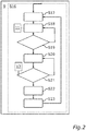
- Fig. 2 shows a method of sending the data frame 3 by the transmitter 9.
- the transmitter 9 may start a transmission gap timer 11 to countdown a predefined transmission gap time 10 (S17). The transmitter 9 may wait until the predefined transmission gap time 10 has elapsed S18.
- a presence of a transmit request 12 to transmit the data frame 3 may be checked by the transmitter 9 of the synchronous serial communication system 2 (S20, S21).
- a transmission process to transmit the data frame 3 to the synchronous communication system 2 may be initialised by the transmitter 9 (S22, S23).
- the transmitter may proceed with step S17.
- a time gap of minimum predefined transmission gap time 10 may be inserted before each data frame 3, transmitted by the transmitter 9 (S17 to S19). Time may be counted from the end of the previously transmitted preceding data frame 6 or from system start up (S17 and S23). The values of these parameters are chosen such that the predefined transmission gap time 10 is bigger than the predefined reception gap time 8.
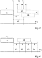
- Fig. 3 shows a timeline of a process of data frame transmission from the transmitter 9 to the receiver 1.
- T1 a transmission of the preceding data frame 6 with the predefined frame size 4 may finish. Therefore, the receiver 1 may start to wait until the predefined reception gap time 8 has finished and the transmitter 9 may wait until the predefined transmission gap time 10 has finished.
- the predefined reception gap time 8 may have elapsed and the receiver 1 may be set up to receive the data frame 3.
- the receiver may be set to discard any data received during the predefined reception gap time 8. For example, if the receiver receives a data frame 3A at TA the respective data frame 3A may be discarded by the receiver 1 because TA is before T2.
- the receiver 1 may be ready to receive a data frame 3B with the predefined frame size 4.
- the transmitter 9 may check for the presence of the transmit request 12 and send a data frame 3C to the receiver 1.
- the system may comprise a predefined number of receivers 1.
- the predefined transmission gap time 10 and the predefined reception gap time 8 may depend on the receiver 1, which has to be addressed by the data frame 3.
- Fig. 4 shows a timeline of a periodic monitoring performed by the receiver 1.
- the periods (P1 to P4) of the periodic monitoring may have the predefined reception gap time 8.
- the receiver 1 may receive at least one byte of a data frame 3D.
- the receiver may discard the data of the data frame 3D.
- the receiver may detect a period P4 without a reception of any byte. Therefore the receiver 1 may be set up to receive the data frame 3 with a predefined frame size 4.
- frame synchronization may be performed using sync words (a unique character or set of characters is placed inside the data frame, usually at the beginning of the frame) or by hardware (for example in Ethernet or CAN).
- Frame synchronization in UART comprises symbol-level synchronization, using start bits.
- Frame synchronization on SPI uses the chip select connection.
- This invention addresses the need for a simple SPI Frame synchronization protocol, build in software, to avoid using the chip select line.
- the invention enables the usage of maximum throughput on the SPI interface with DMA, due to the fixed size of a multi-byte frame.
- the invention avoids the need to search for the sync word by software.
- the SPI chip select signal is not necessary anymore, resulting in reduced hardware cost. Bursts of reception errors do not lead to interrupt overload of the CPU, because the minimum time between interrupts is the predefined reception gap time 8.
- the invention enables the usage of DMA for reception because the transfer size is known (predefined data frame size 4), which may improve performance and decrease CPU load. Resynchronizing after error does not require parsing data to look for a synchronization word. This saves CPU time.
Landscapes
- Engineering & Computer Science (AREA)
- Theoretical Computer Science (AREA)
- Physics & Mathematics (AREA)
- General Engineering & Computer Science (AREA)
- General Physics & Mathematics (AREA)
- Synchronisation In Digital Transmission Systems (AREA)
- Communication Control (AREA)
Abstract
Description
- The invention is concerned with a method of synchronising a receiver of a synchronous serial communication system for a receiving process of a data frame of a predefined frame size from the synchronous serial communication system, a receiver, a transmitter and a system comprising at least one receiver and at least one transmitter.
- In common digital networks data are arranged in data frames or packages. These data frames are sent via a connection between the sender and the receiver. To ensure the transmission between the sender and the receiver, it is necessary, that the receiver identifies the data frame in the data stream of the connection. This process of identification is called frame synchronization.
- Common techniques for frame synchronisation comprise the use of sync words. Sync words are predefined characters at the beginning of a respective data frame. Symbol-level synchronization in Universal Asynchronous Receiver Transmitter (UART) is based on predefined bits at the start and at the end of a respective data frame.
- In Serial Peripheral Interface (SPI) frame synchronisation is performed by using chip selection which uses a special line of the SPI bus system. Serial Peripheral Interface Bus systems comprise at least one SPI master device and at least one SPI slave device. The master device provides a clock signal on one wire of the SPI interface. The clock signal is used for synchronisation between the devices of the Serial Peripheral Interface Bus system. During communication the master sends the clock signal and selects the slave by a specific chip select signal.
- For general purpose serial interfaces like Universal Asynchronous Receiver Transmitter (UART) or Serial Peripheral Interface (SPI), most microcontrollers do not have specialised hardware circuits for doing frame synchronisation on multi-byte frames. In case of Serial Peripheral Interfaces (SPI) the chip select line may be used for this purpose. But this is an additional hardware line which adds to the hardware cost. Classical frame synchronisation using sync words requires data to be parsed to detect the start of a predefined frame pattern. The need to parse data, if not done by hardware, puts a lot of load on the software therefore limiting the throughput of the communication channel due to latencies which need to be considered in design. In addition transmitting continuously without time often means that features like DMA transfer from serial peripheral to memory and vice versa are not possible to use because they require knowing a data size before the transfer starts.
-
US 2012/0140673 A1 disclosures an Inter-frame gap controller, traffic transmitter, transmission apparatus and an inter-frame gap control method. The inter-frame gap controller comprises an inter-frame gap length determiner that determines a length of an inter-frame gap based on traffic volume of Ethernet frames which are converted to synchronous frames and are transmitted over a synchronous network. The inter-frame gap controller comprises a gap inserter that inserts an inter-frame gap of length determined by said inter-frame gap length determiner between Ethernet frames which are converted from said synchronous frames. -
US 9,019,992 B2 -
JPH0753146A - It is an object of the invention to provide a software based method of frame synchronisation without sync words.
- The object is accomplished by the subject matter of the independent claims. Advantageous developments with convenient and non-trivial further embodiments of the invention are specified in the dependent claims, the following description, and the drawings.
- The invention comprises a method of synchronising a receiver of a synchronous serial communication system for a receiving process of a data frame of a predefined frame size from the synchronous serial communication system. In other words, the invention provides a method of frame synchronization for the synchronous serial communication system. The synchronous serial communication system may comply with the Serial Peripheral Interface standard. A synchronisation process comprising a periodic monitoring of the synchronous serial communication system is performed by the receiver. The period of the periodic monitoring has a predefined reception gap time during which the receiver buffers bytes received over the synchronous serial communication system. At the end of each period of the periodic monitoring of the synchronous serial communication system, the respective period is checked for reception of at least one byte by the receiver until a period with no reception of any bytes is detected by the receiver. In other words, the receiver periodically monitors the synchronous serial communication system as long as a period without a reception is detected by the receiver. When a period with no reception of any bytes is detected by the receiver, a frame reception process to receive the data frame of the synchronous serial communication system is initiated by the receiver. In other words, synchronisation of the data frame is performed by the use of the predefined reception gap time. The invention gives the advantage that synchronisation may be performed without an additional data line.
- The invention also comprises embodiments that provide additional technical advantages.
- According to a further embodiment of the invention, the synchronisation process is performed upon termination of a reception of a preceding data frame via the synchronous serial communication system by the receiver. In other words, the receiver initiates the synchronisation process once the reception of the preceding data frame has been completed. The invention has the advantage that the frame synchronisation for receiving the next data frame is performed right after a reception of a previous data frame. It may be possible that the receiver receives the preceding data frame. When the predefined frame size is reached, the receiver may start the synchronisation process to detect the predefined reception gap time.
- According to a further embodiment of the invention, the preceding data frame is considered valid and forwarded to a higher or lower layer of a communication model on initialisation of or during the frame reception process by the receiver. In other words, it is intended to buffer the preceding data frame after the reception until the predefined reception gap time is detected by the receiver. Upon reception of the predefined reception gap time, the preceding data frame is forwarded by the receiver. The preceding data frame is forwarded to a communication layer that differs from the current communication layer. The embodiment gives the advantage that the end of a data frame may be signalized by the first reception gap time after the reception of the data frame. As an example, the preceding data frame may be received by the receiver. The receiver may buffer the preceding data frame, received during the frame reception process. Upon termination of the frame reception process the receiver may initiate the synchronisation process again to detect the predefined reception gap time. When the predefined reception gap time is detected by the receiver, the preceding data frame may be considered valid and forwarded to the higher layer or to the lower layer by the receiver.
- According to a further embodiment of the invention, the receiver is set up to receive the data frame with a predefined frame size during the frame reception process. In other words, during the frame receiving process, the receiver is in a state in which it is adapted to receive the data frame having the predetermined frame size from the synchronous serial communication system. The invention has the advantage that the reception of the data frame is enabled in the frame reception process. As an example, the receiver may be set up to receive data with the predefined frame size to receive the data frame.
- According to a further embodiment of the invention the frame reception process is terminated by the receiver after the reception of the data frame with the predefined frame size. In other words, the frame reception process is terminated when the reception of the data frame is completed. The invention has the advantage that the receiver may initiate another process after the reception of the data frame.
As an example, the receiver may end the reception process when data in the amount of the frame size is received by the receiver. - According to a further embodiment of the invention, the periodic monitoring of the synchronous serial communication system is performed by the receiver again once the frame reception process is completed. In other words, after the reception of the data frame the receiver initiates the synchronisation process to monitor the synchronous serial communication system for a next predefined reception gap time. The invention has the advantage that the reception gap time following a data frame may be used as a stop marker.
- According to a further embodiment of the invention, it is intended that upon elapse of a predefined transmission gap time, a presence of a transmitter request to transmit the data frame is periodically checked by a transmitter of the synchronous serial communication system. Upon presence of the transmitter request, a transmission process to transmit the data frame to the synchronous serial communication system is initialised by the transmitter. Upon termination of the transmission process the transmission gap time is waited again by the transmitter. In other words, the transmitter of the synchronous serial communication system waits until the predefined transmission gap time has expired. After the predefined transmission gap time the transmitter monitors the presence of the transmit request. The presence of the transmit request indicates that the data frame has to be transmitted by the transmitter. When the receiver detects the transmit request, the transmitter initialises the transmission process to transmit the data frame to the synchronous serial communication system. When the transmission of the data frame has ended, the transmitter waits until the transmission gap time has expired. Upon elapse of the transmission gap time, the transmitter monitors the presence of the transmit request again. The embodiment gives the advantage that the transmission gap time ensures a synchronisation between the transmitter and the receiver. It may be possible that the transmitter is connected to the receiver by the synchronous serial communication system. The transmitter may be configured to send the data frame to the synchronous serial communication system. The transmitter may receive the data frame from another device. As soon as another device sends data for transmission by the transmitter, the transmit request may be created or changed. The transmitter may send the data frame, when the transmit request is present or when the transmit request has a specific value. In order to ensure compliance with the reception gap time between successive data frames, the monitoring of the transmit request may be paused in the length of the predefined transmission gap time. Therefore, a lower time limit between the transmissions of successive data frames is set by the predefined transmission gap time.
- The invention comprises a receiver of a synchronous serial communication system. The receiver is configured to perform a synchronisation process comprising a periodic monitoring of the synchronous serial communication system. A period of the periodic monitoring is a predefined reception gap time. The receiver is configured to check a respective period for a reception of at least one byte by the receiver at the end of each period of the periodic monitoring until a period with no reception of any byte is detected. The receiver is configured to initiate a frame reception process to receive the data frame of the synchronous serial communication system, when a period with no reception of any byte is detected.
- The invention comprises a transmitter of a synchronous serial communication system. The transmitter is configured to periodically check the presence of the transmit request to transmit the data frame upon elapse of the predefined transmission gap time. The transmitter is configured to initialise the transmission process to transmit the data frame to the synchronous serial communication system upon presence of transmit request. The transmitter is configured to wait the transmission gap time again upon termination of the transmission process.
- The invention comprises a system comprising at least one transmitter and at least one receiver.
- The invention also comprises the combinations of the features of the described embodiments.
- In the following an exemplary implementation of the invention is described. The figures show:
- Fig. 1
- a method of synchronising a receiver of a synchronous serial communication system for a receiving process of a data frame;
- Fig. 2
- a method of sending the data frame by a transmitter;
- Fig. 3
- a timeline of a process of data frame transmission from the transmitter to the receiver; and
- Fig. 4
- a timeline of a periodic monitoring performed by the receiver.
- The embodiment explained in the following is a preferred embodiment of the invention. However, in the embodiment, the described components of the embodiment each represent individual features of the invention which are to be considered independently of each other and which each develop the invention also independently of each other and thereby are also to be regarded as a component of the invention in individual manner or in another than the shown combination. Furthermore, the described embodiment can also be supplemented by further features of the invention already described.
- In the figures elements that provide the same function are marked with identical reference signs.
-
Fig. 1 shows a method of synchronising areceiver 1 of a synchronousserial communication system 2 for a receiving process of adata frame 3 of apredefined frame size 4 from the synchronousserial communication system 2. At start-up of thereceiver 1 or after the reception of anerror signal 5 by thereceiver 1, the synchronisation process S1 may be initialised by thereceiver 1. The synchronisation process S1 may comprise a periodic monitoring of the synchronousserial communication system 2 by thereceiver 1. In the 1st step S2 of the synchronisation process S1 a parameter DATAAVAILABLE that indicates that a precedingdata frame 6 is cached by thereceiver 1 may be set to a state NO. In the following step S3, thereceiver 1 may clear previous reception events related to a reception of the precedingdata frame 6. In step S4 thereceiver 1 may be set up for a reception of at least one byte. In the step S5 areception gap timer 7 of thereceiver 1 may start a countdown of a predefinedreception gap time 8. Thereceiver 1 may wait until the predefinedreception gap time 8 has expired (S6, S7). At the end of each period of the periodic monitoring of the synchronousserial communication system 2, the respective period may be checked for the reception of at least one byte by thereceiver 1 until a period with no reception of any byte is detected by the receiver 1 (S8). If at least one byte is received from thereceiver 1 during a period, the data received in that period may be discarded and thereceiver 1 may proceed to step S2. Upon detection of a period without a reception, thereceiver 1 may end the synchronisation process S1 and start a frame reception process S9. - In the first step S10 of the frame reception process S9 the
receiver 1 may check the state of the parameter DATAAVAILABLE to check the presence of the precedingdata frame 6. If the state of the parameter DATAAVAILABLE is YES, the precedingdata frame 6 may be saved in a memory of thereceiver 1. In that case, the precedingdata frame 6 may be considered correct and forwarded to an upper layer by the receiver 1 (S11). After the forwarding, thereceiver 1 may be set up to receive thedata frame 3 with thepredefined frame size 4 or any error (S12). In other words, thereceiver 1 may be set in a state for the reception of thedata frame 3. If the state of the parameter DATAAVAILABLE is NO, thereceiver 1 may continue with step S12. In a step S13, thereceiver 1 may receive thedata frame 3. Thereceiver 1 may periodically check, whether the reception of thedata frame 3 has finished (S14). If thereceiver 1 receives an error signal during step S13, thereceiver 1 may discard all parts of thedata frame 3 it has received so far in this session, send theerror signal 5 and continue with step S2. If the reception process has been successfully completed, thedata frame 3 can be buffered by thereceiver 1. In step S15 thereceiver 1 may set the value DATAAVAILABLE to YES, to signal, that thedata frame 3 is cached by thereceiver 1. After step S15, thereceiver 1 may proceed with step S3. - The invention may be configured as a software algorithm for frame synchronization on SPI. The
data frame 3 in this context may consist of a group of bytes of the fixed, predefined data fixedframe size 4. Sequential data frames 3 may be separated by a minimum inter-frame time. On receiver side (seeFig.1 ), the algorithm may search for a bus idle timegap of minimum predefined duration after each reception of a data frame. The minimum predefined duration may be defined as the predefinedreception gap time 8. - As seen in the activity diagram in
Fig. 1 , at start up, after a reception of theerror signal 5 and after a successful reception of the precedingdata frame 6, thereceiver 1 may be cleared of all previous reception events. Thereceiver 1 may be set up to detect the reception of at least one byte (S2 to S4). Then thereception gap timer 7 of thereceiver 1 may be started to count down the predefined reception gap time 8 (S5). The timer may be any general-purpose timer of a microcontroller or a software timer. Hence the bus is monitored during the predefinedreception gap time 8 for any activity. When the timer expires (S7), the state of reception may be checked (S8). If there was any reception event detected during the predefined reception gap time 8 (reception of at least one byte or reception error), the received data may be discarded (S2) by thereceiver 1 and thereceiver 1 may be set up again to detect at least one byte and reception errors. Thereception gap timer 7 may be started again (S2 to S5). These steps may be repeated until a time-gap is found. So, for as long as the communication is erroneous or de-synchronized, the algorithm will search for an idle time of at least the predefinedreception gap time 8 with the purpose of re-synchronizing with the transmitter. If there was no reception event during the predefinedreception gap time 8 and a completepreceding data frame 6 of the predefineddata frame size 4 was received, then the precedingdata frame 6 may be considered correct by thereceiver 1 and forwarded to an upper layer (S10, S11). Afterwards, reception is setup to trigger at reception of the complete data frame of the predefined frame size or on any reception error (S12). If this reception succeeds without error, the data frame may be considered valid (S14, S15) and the searching for gap time is restarted (S2) to (S8). If there were reception errors after setup of FrameSize bytes reception (S4), the data may be discarded (S2) and searching for gap time may be restarted (S3 to S7). -
Fig. 2 shows a method of sending thedata frame 3 by thetransmitter 9. In a first step of the transmission method S16 thetransmitter 9 may start atransmission gap timer 11 to countdown a predefined transmission gap time 10 (S17). Thetransmitter 9 may wait until the predefinedtransmission gap time 10 has elapsed S18. Upon elapse of the predefinedtransmission gap time 10, a presence of a transmitrequest 12 to transmit thedata frame 3, may be checked by thetransmitter 9 of the synchronous serial communication system 2 (S20, S21). Upon presence of the transmit request 12 a transmission process to transmit thedata frame 3 to thesynchronous communication system 2 may be initialised by the transmitter 9 (S22, S23). Upon termination of the transmission process, the transmitter may proceed with step S17. - On transmitter side (
Fig. 2 ), a time gap of minimum predefinedtransmission gap time 10 may be inserted before eachdata frame 3, transmitted by the transmitter 9 (S17 to S19). Time may be counted from the end of the previously transmitted precedingdata frame 6 or from system start up (S17 and S23). The values of these parameters are chosen such that the predefinedtransmission gap time 10 is bigger than the predefinedreception gap time 8. -
Fig. 3 shows a timeline of a process of data frame transmission from thetransmitter 9 to thereceiver 1. At T1 a transmission of the precedingdata frame 6 with thepredefined frame size 4 may finish. Therefore, thereceiver 1 may start to wait until the predefinedreception gap time 8 has finished and thetransmitter 9 may wait until the predefinedtransmission gap time 10 has finished. At the moment T2, the predefinedreception gap time 8 may have elapsed and thereceiver 1 may be set up to receive thedata frame 3. During the predefined reception gap time 8 (T1 to T2) the receiver may be set to discard any data received during the predefinedreception gap time 8. For example, if the receiver receives adata frame 3A at TA therespective data frame 3A may be discarded by thereceiver 1 because TA is before T2. After T2 thereceiver 1 may be ready to receive adata frame 3B with thepredefined frame size 4. After the predefinedtransmission gap time 10 thetransmitter 9 may check for the presence of the transmitrequest 12 and send adata frame 3C to thereceiver 1. The system may comprise a predefined number ofreceivers 1. The predefinedtransmission gap time 10 and the predefinedreception gap time 8 may depend on thereceiver 1, which has to be addressed by thedata frame 3. -
Fig. 4 shows a timeline of a periodic monitoring performed by thereceiver 1. After a reception of the precedingdata frame 6 with thepredefined frame size 4 thereceiver 1 may initiate the periodic monitoring. The periods (P1 to P4) of the periodic monitoring may have the predefinedreception gap time 8. During the first period P1, thereceiver 1 may receive at least one byte of adata frame 3D. As the byte is received before the end of the first period P1, the receiver may discard the data of thedata frame 3D. After period P3, the receiver may detect a period P4 without a reception of any byte. Therefore thereceiver 1 may be set up to receive thedata frame 3 with apredefined frame size 4. - According to the state of the art frame synchronization may be performed using sync words (a unique character or set of characters is placed inside the data frame, usually at the beginning of the frame) or by hardware (for example in Ethernet or CAN). Frame synchronization in UART comprises symbol-level synchronization, using start bits. Frame synchronization on SPI uses the chip select connection.
- For general purpose serial interfaces, like UART or SPI, most microcontrollers do not have specialized hardware circuits for doing frame synchronization on multi-byte frames. In case of SPI, the chip select line may be used for this purpose, but this is an additional hardware line, which may increase hardware cost. Classical Frame synchronization using sync words requires data to be parsed to detect the start of the respective data frame pattern.
- The need to parse data, if not done by hardware, puts a lot of load on the software, therefor limiting the throughput of the communication channel, due to latencies which need to be considered in design. In addition, transmitting continuously, without time gap, often means that features like DMA transfer (from serial peripheral to memory and vice-versa) are not possible to use, because they require knowing the data size before the transfer starts.
- This invention addresses the need for a simple SPI Frame synchronization protocol, build in software, to avoid using the chip select line. The invention enables the usage of maximum throughput on the SPI interface with DMA, due to the fixed size of a multi-byte frame. The invention avoids the need to search for the sync word by software.
- The SPI chip select signal is not necessary anymore, resulting in reduced hardware cost. Bursts of reception errors do not lead to interrupt overload of the CPU, because the minimum time between interrupts is the predefined
reception gap time 8. The invention enables the usage of DMA for reception because the transfer size is known (predefined data frame size 4), which may improve performance and decrease CPU load. Resynchronizing after error does not require parsing data to look for a synchronization word. This saves CPU time. - Overall, the example shows how a software frame synchronization algorithm for fixed-size multi-byte data on SPI is provided by the invention.
Claims (10)
- Method of synchronizing a receiver (1) in a synchronous serial communication system (2) for receiving a data frame (3) of a predefined frame size (4) over the synchronous serial communication system (2),
characterized in that- a synchronisation process comprising a periodic monitoring of the synchronous serial communication system (2) is performed by the receiver (1), wherein- a period of the periodic monitoring has a predefined reception gap time (8), during which the receiver (1) buffers bytes received over the synchronous serial communication system (2),- at the end of each period of the periodic monitoring of the synchronous serial communication system (2), the respective period is checked for a reception of at least one byte by the receiver (1), until a period with no reception of any byte is detected by the receiver (1), and then- a frame reception process to receive the data frame (3) of the synchronous serial communication system (2) is initiated by the receiver (1). - Method according to claim 1,
characterized in that
the periodic monitoring of the synchronous serial communication system (2) is performed upon termination of the reception of a preceding data frame (6) via the synchronous serial communication system (2) by the receiver (1). - Method according to claim 2,
characterized in that
upon initialisation of or during the frame reception process, the preceding data frame (6) received via the synchronous serial communication system (2) by the receiver (1) is considered valid and forwarded to a higher or lower layer of a communication model. - Method according to one of the preceding claims,
characterized in that
for the frame reception process, the receiver (1) is set up to receive the data frame (3) with the predefined frame size (4). - Method according to claim 4,
characterized in that
after the reception of the data frame (3) with the predefined frame size (4), the frame reception process is terminated by the receiver (1). - Method according to claim 5,
characterized in that
upon termination of the frame reception process, the periodic monitoring of the synchronous serial communication system (2) is performed by the receiver (1) again. - Method according to one of the preceding claims,
characterized in that- upon elapse of a predefined transmission gap time (10), a presence of a transmit request to transmit a data frame (3) is periodically checked by a transmitter (9) of the synchronous serial communication system (2),- upon presence of the transmit request, a transmission process to transmit the data frame (3) to the synchronous serial communication system (2) is initialized by the transmitter (9), and- upon termination of the transmission process, the transmission gap time (10) is waited again by the transmitter (9). - Receiver (1) of a synchronous serial communication system (2),
characterized in that
the receiver (1) is configured to perform a synchronisation process comprising a periodic monitoring of the synchronous serial communication system (2), wherein- a period of the periodic monitoring has a predefined reception gap time (8), during which the receiver (1) buffers bytes received over the synchronous serial communication system (2),the receiver (1) is configured to check a respective period for a reception of at least one byte by the receiver (1) at the end of each period of the periodic monitoring of the synchronous serial communication system (2), until a period with no reception of any byte is detected, and- the receiver (1) is configured to initiate a frame reception process to receive the data frame (3) of the synchronous serial communication system (2). - Transmitter (9) of a synchronous serial communication system (2),
characterized in that
the transmitter (9) is configured to- periodically check a presence of a transmit request to transmit a data frame (3), upon elapse of a predefined transmission gap time (10),- initialize a transmission process to transmit the data frame (3) to the synchronous serial communication system (2) upon presence of the transmit request, and- wait the transmission gap time (10) again upon termination of the transmission process. - Synchronous serial communication system (2), comprising at least one transmitter (9) according to claim 9 and at least one receiver according to claim 8.
Priority Applications (1)
| Application Number | Priority Date | Filing Date | Title |
|---|---|---|---|
| EP19465581.7A EP3812912B1 (en) | 2019-10-22 | 2019-10-22 | Method of synchronizing a receiver of a synchronous serial communication system for a receiving process of a data frame of a predefined frame size from the synchronous serial communication system, receiver, transmitter and system |
Applications Claiming Priority (1)
| Application Number | Priority Date | Filing Date | Title |
|---|---|---|---|
| EP19465581.7A EP3812912B1 (en) | 2019-10-22 | 2019-10-22 | Method of synchronizing a receiver of a synchronous serial communication system for a receiving process of a data frame of a predefined frame size from the synchronous serial communication system, receiver, transmitter and system |
Publications (2)
| Publication Number | Publication Date |
|---|---|
| EP3812912A1 true EP3812912A1 (en) | 2021-04-28 |
| EP3812912B1 EP3812912B1 (en) | 2023-03-22 |
Family
ID=68426390
Family Applications (1)
| Application Number | Title | Priority Date | Filing Date |
|---|---|---|---|
| EP19465581.7A Active EP3812912B1 (en) | 2019-10-22 | 2019-10-22 | Method of synchronizing a receiver of a synchronous serial communication system for a receiving process of a data frame of a predefined frame size from the synchronous serial communication system, receiver, transmitter and system |
Country Status (1)
| Country | Link |
|---|---|
| EP (1) | EP3812912B1 (en) |
Citations (5)
| Publication number | Priority date | Publication date | Assignee | Title |
|---|---|---|---|---|
| US4199663A (en) * | 1978-11-06 | 1980-04-22 | The Boeing Company | Autonomous terminal data communications system |
| JPH0753146A (en) | 1993-06-01 | 1995-02-28 | Otis Elevator Co | Man lift communication network of local area network system |
| EP1909440A1 (en) * | 2005-07-06 | 2008-04-09 | NEC Corporation | Bandwidth control circuit and bandwidth control method used therefor |
| US20120140673A1 (en) | 2009-09-02 | 2012-06-07 | Fujitsu Limited | Inter-frame gap controller, traffic transmitter, transmission apparatus and inter-frame gap control method |
| US9019992B2 (en) | 2013-01-08 | 2015-04-28 | Tangome, Inc. | Joint retransmission and frame synchronization for error resilience control |
-
2019
- 2019-10-22 EP EP19465581.7A patent/EP3812912B1/en active Active
Patent Citations (5)
| Publication number | Priority date | Publication date | Assignee | Title |
|---|---|---|---|---|
| US4199663A (en) * | 1978-11-06 | 1980-04-22 | The Boeing Company | Autonomous terminal data communications system |
| JPH0753146A (en) | 1993-06-01 | 1995-02-28 | Otis Elevator Co | Man lift communication network of local area network system |
| EP1909440A1 (en) * | 2005-07-06 | 2008-04-09 | NEC Corporation | Bandwidth control circuit and bandwidth control method used therefor |
| US20120140673A1 (en) | 2009-09-02 | 2012-06-07 | Fujitsu Limited | Inter-frame gap controller, traffic transmitter, transmission apparatus and inter-frame gap control method |
| US9019992B2 (en) | 2013-01-08 | 2015-04-28 | Tangome, Inc. | Joint retransmission and frame synchronization for error resilience control |
Also Published As
| Publication number | Publication date |
|---|---|
| EP3812912B1 (en) | 2023-03-22 |
Similar Documents
| Publication | Publication Date | Title |
|---|---|---|
| EP2239880B1 (en) | Gateway and base station based on content synchronization of window and its method | |
| CN100469172C (en) | Wireless communication system with robust radio link control reset procedure | |
| US7460509B2 (en) | Method and apparatus for isochronous datagram delivery over contention-based data link | |
| RU2460214C2 (en) | Status message initiation in wireless communication system | |
| TWI358922B (en) | Method and apparatus of default timer configuratio | |
| US8274920B2 (en) | Token bus communication system | |
| US6990079B2 (en) | Optimizing fragment sizes in frame relay networks | |
| CN104703053A (en) | Packet loss processing method, device and system of video transmission process | |
| US8391285B2 (en) | Communication apparatus, communication system, and communication method | |
| EP3812912B1 (en) | Method of synchronizing a receiver of a synchronous serial communication system for a receiving process of a data frame of a predefined frame size from the synchronous serial communication system, receiver, transmitter and system | |
| CN105940658A (en) | A user data transmission method, apparatus and terminal | |
| EP2916523B1 (en) | Data stream and data packet transmission method and device | |
| US7508813B2 (en) | Local area network contention avoidance | |
| EP3739820B9 (en) | Establishing communication at optimized time instances | |
| JP3855945B2 (en) | Interface converter | |
| US20110158243A1 (en) | Method of data transmission, data transmitting apparatus, and network system | |
| EP1376960A1 (en) | Data link layer device with two transmission modes for a serial communication bus | |
| CN111934820A (en) | Management information transmission method, system and readable storage medium | |
| US20050074057A1 (en) | System and method for modulation on demand in a computing device | |
| US8274997B2 (en) | Transmission method and reception method | |
| JP3819228B2 (en) | Terminal device and communication method | |
| KR20250140403A (en) | Apparatus and method for transmitting bluetooth low energy data | |
| TW202520698A (en) | Communication method and communication device | |
| CN121841533A (en) | Lightweight time synchronization and performance monitoring methods for data center networks | |
| CN121585302A (en) | Time synchronization method, apparatus, storage medium, and electronic device based on confirmation frames piggybacked with timestamps |
Legal Events
| Date | Code | Title | Description |
|---|---|---|---|
| PUAI | Public reference made under article 153(3) epc to a published international application that has entered the european phase |
Free format text: ORIGINAL CODE: 0009012 |
|
| STAA | Information on the status of an ep patent application or granted ep patent |
Free format text: STATUS: THE APPLICATION HAS BEEN PUBLISHED |
|
| AK | Designated contracting states |
Kind code of ref document: A1 Designated state(s): AL AT BE BG CH CY CZ DE DK EE ES FI FR GB GR HR HU IE IS IT LI LT LU LV MC MK MT NL NO PL PT RO RS SE SI SK SM TR |
|
| AX | Request for extension of the european patent |
Extension state: BA ME |
|
| STAA | Information on the status of an ep patent application or granted ep patent |
Free format text: STATUS: REQUEST FOR EXAMINATION WAS MADE |
|
| 17P | Request for examination filed |
Effective date: 20211028 |
|
| RBV | Designated contracting states (corrected) |
Designated state(s): AL AT BE BG CH CY CZ DE DK EE ES FI FR GB GR HR HU IE IS IT LI LT LU LV MC MK MT NL NO PL PT RO RS SE SI SK SM TR |
|
| RAP1 | Party data changed (applicant data changed or rights of an application transferred) |
Owner name: CONTINENTAL AUTOMOTIVE TECHNOLOGIES GMBH |
|
| GRAP | Despatch of communication of intention to grant a patent |
Free format text: ORIGINAL CODE: EPIDOSNIGR1 |
|
| STAA | Information on the status of an ep patent application or granted ep patent |
Free format text: STATUS: GRANT OF PATENT IS INTENDED |
|
| GRAJ | Information related to disapproval of communication of intention to grant by the applicant or resumption of examination proceedings by the epo deleted |
Free format text: ORIGINAL CODE: EPIDOSDIGR1 |
|
| STAA | Information on the status of an ep patent application or granted ep patent |
Free format text: STATUS: REQUEST FOR EXAMINATION WAS MADE |
|
| INTG | Intention to grant announced |
Effective date: 20221107 |
|
| GRAP | Despatch of communication of intention to grant a patent |
Free format text: ORIGINAL CODE: EPIDOSNIGR1 |
|
| STAA | Information on the status of an ep patent application or granted ep patent |
Free format text: STATUS: GRANT OF PATENT IS INTENDED |
|
| INTG | Intention to grant announced |
Effective date: 20221202 |
|
| GRAS | Grant fee paid |
Free format text: ORIGINAL CODE: EPIDOSNIGR3 |
|
| GRAA | (expected) grant |
Free format text: ORIGINAL CODE: 0009210 |
|
| STAA | Information on the status of an ep patent application or granted ep patent |
Free format text: STATUS: THE PATENT HAS BEEN GRANTED |
|
| AK | Designated contracting states |
Kind code of ref document: B1 Designated state(s): AL AT BE BG CH CY CZ DE DK EE ES FI FR GB GR HR HU IE IS IT LI LT LU LV MC MK MT NL NO PL PT RO RS SE SI SK SM TR |
|
| REG | Reference to a national code |
Ref country code: GB Ref legal event code: FG4D |
|
| REG | Reference to a national code |
Ref country code: CH Ref legal event code: EP |
|
| REG | Reference to a national code |
Ref country code: IE Ref legal event code: FG4D |
|
| REG | Reference to a national code |
Ref country code: DE Ref legal event code: R096 Ref document number: 602019026634 Country of ref document: DE |
|
| REG | Reference to a national code |
Ref country code: AT Ref legal event code: REF Ref document number: 1555732 Country of ref document: AT Kind code of ref document: T Effective date: 20230415 |
|
| REG | Reference to a national code |
Ref country code: SE Ref legal event code: TRGR |
|
| P01 | Opt-out of the competence of the unified patent court (upc) registered |
Effective date: 20230522 |
|
| REG | Reference to a national code |
Ref country code: LT Ref legal event code: MG9D |
|
| REG | Reference to a national code |
Ref country code: NL Ref legal event code: MP Effective date: 20230322 |
|
| PG25 | Lapsed in a contracting state [announced via postgrant information from national office to epo] |
Ref country code: RS Free format text: LAPSE BECAUSE OF FAILURE TO SUBMIT A TRANSLATION OF THE DESCRIPTION OR TO PAY THE FEE WITHIN THE PRESCRIBED TIME-LIMIT Effective date: 20230322 Ref country code: NO Free format text: LAPSE BECAUSE OF FAILURE TO SUBMIT A TRANSLATION OF THE DESCRIPTION OR TO PAY THE FEE WITHIN THE PRESCRIBED TIME-LIMIT Effective date: 20230622 Ref country code: LV Free format text: LAPSE BECAUSE OF FAILURE TO SUBMIT A TRANSLATION OF THE DESCRIPTION OR TO PAY THE FEE WITHIN THE PRESCRIBED TIME-LIMIT Effective date: 20230322 Ref country code: LT Free format text: LAPSE BECAUSE OF FAILURE TO SUBMIT A TRANSLATION OF THE DESCRIPTION OR TO PAY THE FEE WITHIN THE PRESCRIBED TIME-LIMIT Effective date: 20230322 Ref country code: HR Free format text: LAPSE BECAUSE OF FAILURE TO SUBMIT A TRANSLATION OF THE DESCRIPTION OR TO PAY THE FEE WITHIN THE PRESCRIBED TIME-LIMIT Effective date: 20230322 |
|
| REG | Reference to a national code |
Ref country code: AT Ref legal event code: MK05 Ref document number: 1555732 Country of ref document: AT Kind code of ref document: T Effective date: 20230322 |
|
| PG25 | Lapsed in a contracting state [announced via postgrant information from national office to epo] |
Ref country code: NL Free format text: LAPSE BECAUSE OF FAILURE TO SUBMIT A TRANSLATION OF THE DESCRIPTION OR TO PAY THE FEE WITHIN THE PRESCRIBED TIME-LIMIT Effective date: 20230322 Ref country code: GR Free format text: LAPSE BECAUSE OF FAILURE TO SUBMIT A TRANSLATION OF THE DESCRIPTION OR TO PAY THE FEE WITHIN THE PRESCRIBED TIME-LIMIT Effective date: 20230623 Ref country code: FI Free format text: LAPSE BECAUSE OF FAILURE TO SUBMIT A TRANSLATION OF THE DESCRIPTION OR TO PAY THE FEE WITHIN THE PRESCRIBED TIME-LIMIT Effective date: 20230322 |
|
| PG25 | Lapsed in a contracting state [announced via postgrant information from national office to epo] |
Ref country code: SM Free format text: LAPSE BECAUSE OF FAILURE TO SUBMIT A TRANSLATION OF THE DESCRIPTION OR TO PAY THE FEE WITHIN THE PRESCRIBED TIME-LIMIT Effective date: 20230322 Ref country code: RO Free format text: LAPSE BECAUSE OF FAILURE TO SUBMIT A TRANSLATION OF THE DESCRIPTION OR TO PAY THE FEE WITHIN THE PRESCRIBED TIME-LIMIT Effective date: 20230322 Ref country code: PT Free format text: LAPSE BECAUSE OF FAILURE TO SUBMIT A TRANSLATION OF THE DESCRIPTION OR TO PAY THE FEE WITHIN THE PRESCRIBED TIME-LIMIT Effective date: 20230724 Ref country code: ES Free format text: LAPSE BECAUSE OF FAILURE TO SUBMIT A TRANSLATION OF THE DESCRIPTION OR TO PAY THE FEE WITHIN THE PRESCRIBED TIME-LIMIT Effective date: 20230322 Ref country code: EE Free format text: LAPSE BECAUSE OF FAILURE TO SUBMIT A TRANSLATION OF THE DESCRIPTION OR TO PAY THE FEE WITHIN THE PRESCRIBED TIME-LIMIT Effective date: 20230322 Ref country code: AT Free format text: LAPSE BECAUSE OF FAILURE TO SUBMIT A TRANSLATION OF THE DESCRIPTION OR TO PAY THE FEE WITHIN THE PRESCRIBED TIME-LIMIT Effective date: 20230322 |
|
| PG25 | Lapsed in a contracting state [announced via postgrant information from national office to epo] |
Ref country code: SK Free format text: LAPSE BECAUSE OF FAILURE TO SUBMIT A TRANSLATION OF THE DESCRIPTION OR TO PAY THE FEE WITHIN THE PRESCRIBED TIME-LIMIT Effective date: 20230322 Ref country code: PL Free format text: LAPSE BECAUSE OF FAILURE TO SUBMIT A TRANSLATION OF THE DESCRIPTION OR TO PAY THE FEE WITHIN THE PRESCRIBED TIME-LIMIT Effective date: 20230322 Ref country code: IS Free format text: LAPSE BECAUSE OF FAILURE TO SUBMIT A TRANSLATION OF THE DESCRIPTION OR TO PAY THE FEE WITHIN THE PRESCRIBED TIME-LIMIT Effective date: 20230722 |
|
| REG | Reference to a national code |
Ref country code: DE Ref legal event code: R097 Ref document number: 602019026634 Country of ref document: DE |
|
| PLBE | No opposition filed within time limit |
Free format text: ORIGINAL CODE: 0009261 |
|
| STAA | Information on the status of an ep patent application or granted ep patent |
Free format text: STATUS: NO OPPOSITION FILED WITHIN TIME LIMIT |
|
| PG25 | Lapsed in a contracting state [announced via postgrant information from national office to epo] |
Ref country code: SI Free format text: LAPSE BECAUSE OF FAILURE TO SUBMIT A TRANSLATION OF THE DESCRIPTION OR TO PAY THE FEE WITHIN THE PRESCRIBED TIME-LIMIT Effective date: 20230322 Ref country code: DK Free format text: LAPSE BECAUSE OF FAILURE TO SUBMIT A TRANSLATION OF THE DESCRIPTION OR TO PAY THE FEE WITHIN THE PRESCRIBED TIME-LIMIT Effective date: 20230322 Ref country code: CZ Free format text: LAPSE BECAUSE OF FAILURE TO SUBMIT A TRANSLATION OF THE DESCRIPTION OR TO PAY THE FEE WITHIN THE PRESCRIBED TIME-LIMIT Effective date: 20230322 |
|
| REG | Reference to a national code |
Ref country code: DE Ref legal event code: R081 Ref document number: 602019026634 Country of ref document: DE Owner name: CONTINENTAL AUTOMOTIVE TECHNOLOGIES GMBH, DE Free format text: FORMER OWNER: CONTINENTAL AUTOMOTIVE TECHNOLOGIES GMBH, 30165 HANNOVER, DE Ref country code: DE Ref legal event code: R081 Ref document number: 602019026634 Country of ref document: DE Owner name: AUMOVIO GERMANY GMBH, DE Free format text: FORMER OWNER: CONTINENTAL AUTOMOTIVE TECHNOLOGIES GMBH, 30165 HANNOVER, DE |
|
| 26N | No opposition filed |
Effective date: 20240102 |
|
| PG25 | Lapsed in a contracting state [announced via postgrant information from national office to epo] |
Ref country code: IT Free format text: LAPSE BECAUSE OF FAILURE TO SUBMIT A TRANSLATION OF THE DESCRIPTION OR TO PAY THE FEE WITHIN THE PRESCRIBED TIME-LIMIT Effective date: 20230322 Ref country code: MC Free format text: LAPSE BECAUSE OF FAILURE TO SUBMIT A TRANSLATION OF THE DESCRIPTION OR TO PAY THE FEE WITHIN THE PRESCRIBED TIME-LIMIT Effective date: 20230322 |
|
| REG | Reference to a national code |
Ref country code: CH Ref legal event code: PL |
|
| REG | Reference to a national code |
Ref country code: BE Ref legal event code: MM Effective date: 20231031 |
|
| PG25 | Lapsed in a contracting state [announced via postgrant information from national office to epo] |
Ref country code: LU Free format text: LAPSE BECAUSE OF NON-PAYMENT OF DUE FEES Effective date: 20231022 |
|
| GBPC | Gb: european patent ceased through non-payment of renewal fee |
Effective date: 20231022 |
|
| PG25 | Lapsed in a contracting state [announced via postgrant information from national office to epo] |
Ref country code: LU Free format text: LAPSE BECAUSE OF NON-PAYMENT OF DUE FEES Effective date: 20231022 |
|
| PG25 | Lapsed in a contracting state [announced via postgrant information from national office to epo] |
Ref country code: GB Free format text: LAPSE BECAUSE OF NON-PAYMENT OF DUE FEES Effective date: 20231022 |
|
| PG25 | Lapsed in a contracting state [announced via postgrant information from national office to epo] |
Ref country code: CH Free format text: LAPSE BECAUSE OF NON-PAYMENT OF DUE FEES Effective date: 20231031 |
|
| PG25 | Lapsed in a contracting state [announced via postgrant information from national office to epo] |
Ref country code: GB Free format text: LAPSE BECAUSE OF NON-PAYMENT OF DUE FEES Effective date: 20231022 Ref country code: CH Free format text: LAPSE BECAUSE OF NON-PAYMENT OF DUE FEES Effective date: 20231031 |
|
| PG25 | Lapsed in a contracting state [announced via postgrant information from national office to epo] |
Ref country code: BE Free format text: LAPSE BECAUSE OF NON-PAYMENT OF DUE FEES Effective date: 20231031 |
|
| PG25 | Lapsed in a contracting state [announced via postgrant information from national office to epo] |
Ref country code: IE Free format text: LAPSE BECAUSE OF NON-PAYMENT OF DUE FEES Effective date: 20231022 |
|
| PG25 | Lapsed in a contracting state [announced via postgrant information from national office to epo] |
Ref country code: IE Free format text: LAPSE BECAUSE OF NON-PAYMENT OF DUE FEES Effective date: 20231022 |
|
| PG25 | Lapsed in a contracting state [announced via postgrant information from national office to epo] |
Ref country code: BG Free format text: LAPSE BECAUSE OF FAILURE TO SUBMIT A TRANSLATION OF THE DESCRIPTION OR TO PAY THE FEE WITHIN THE PRESCRIBED TIME-LIMIT Effective date: 20230322 |
|
| PG25 | Lapsed in a contracting state [announced via postgrant information from national office to epo] |
Ref country code: BG Free format text: LAPSE BECAUSE OF FAILURE TO SUBMIT A TRANSLATION OF THE DESCRIPTION OR TO PAY THE FEE WITHIN THE PRESCRIBED TIME-LIMIT Effective date: 20230322 |
|
| PG25 | Lapsed in a contracting state [announced via postgrant information from national office to epo] |
Ref country code: CY Free format text: LAPSE BECAUSE OF FAILURE TO SUBMIT A TRANSLATION OF THE DESCRIPTION OR TO PAY THE FEE WITHIN THE PRESCRIBED TIME-LIMIT; INVALID AB INITIO Effective date: 20191022 |
|
| PG25 | Lapsed in a contracting state [announced via postgrant information from national office to epo] |
Ref country code: HU Free format text: LAPSE BECAUSE OF FAILURE TO SUBMIT A TRANSLATION OF THE DESCRIPTION OR TO PAY THE FEE WITHIN THE PRESCRIBED TIME-LIMIT; INVALID AB INITIO Effective date: 20191022 |
|
| PG25 | Lapsed in a contracting state [announced via postgrant information from national office to epo] |
Ref country code: TR Free format text: LAPSE BECAUSE OF FAILURE TO SUBMIT A TRANSLATION OF THE DESCRIPTION OR TO PAY THE FEE WITHIN THE PRESCRIBED TIME-LIMIT Effective date: 20230322 |
|
| PGFP | Annual fee paid to national office [announced via postgrant information from national office to epo] |
Ref country code: DE Payment date: 20251031 Year of fee payment: 7 |
|
| PGFP | Annual fee paid to national office [announced via postgrant information from national office to epo] |
Ref country code: FR Payment date: 20251027 Year of fee payment: 7 |
|
| PGFP | Annual fee paid to national office [announced via postgrant information from national office to epo] |
Ref country code: SE Payment date: 20251024 Year of fee payment: 7 |
|
| REG | Reference to a national code |
Ref country code: DE Ref legal event code: R081 Ref document number: 602019026634 Country of ref document: DE Owner name: AUMOVIO GERMANY GMBH, DE Free format text: FORMER OWNER: CONTINENTAL AUTOMOTIVE TECHNOLOGIES GMBH, 30175 HANNOVER, DE |