EP3812760B1 - Flat plate sample holder expanding structure for use in vacuum - Google Patents
Flat plate sample holder expanding structure for use in vacuum Download PDFInfo
- Publication number
- EP3812760B1 EP3812760B1 EP18923278.8A EP18923278A EP3812760B1 EP 3812760 B1 EP3812760 B1 EP 3812760B1 EP 18923278 A EP18923278 A EP 18923278A EP 3812760 B1 EP3812760 B1 EP 3812760B1
- Authority
- EP
- European Patent Office
- Prior art keywords
- sample holder
- flat plate
- plate sample
- cylindrical
- adapter
- Prior art date
- Legal status (The legal status is an assumption and is not a legal conclusion. Google has not performed a legal analysis and makes no representation as to the accuracy of the status listed.)
- Active
Links
Images


Classifications
-
- G—PHYSICS
- G01—MEASURING; TESTING
- G01N—INVESTIGATING OR ANALYSING MATERIALS BY DETERMINING THEIR CHEMICAL OR PHYSICAL PROPERTIES
- G01N1/00—Sampling; Preparing specimens for investigation
- G01N1/28—Preparing specimens for investigation including physical details of (bio-)chemical methods covered elsewhere, e.g. G01N33/50, C12Q
- G01N1/36—Embedding or analogous mounting of samples
-
- G—PHYSICS
- G01—MEASURING; TESTING
- G01N—INVESTIGATING OR ANALYSING MATERIALS BY DETERMINING THEIR CHEMICAL OR PHYSICAL PROPERTIES
- G01N23/00—Investigating or analysing materials by the use of wave or particle radiation, e.g. X-rays or neutrons, not covered by groups G01N3/00 – G01N17/00, G01N21/00 or G01N22/00
- G01N23/22—Investigating or analysing materials by the use of wave or particle radiation, e.g. X-rays or neutrons, not covered by groups G01N3/00 – G01N17/00, G01N21/00 or G01N22/00 by measuring secondary emission from the material
- G01N23/2204—Specimen supports therefor; Sample conveying means therefore
-
- G—PHYSICS
- G01—MEASURING; TESTING
- G01L—MEASURING FORCE, STRESS, TORQUE, WORK, MECHANICAL POWER, MECHANICAL EFFICIENCY, OR FLUID PRESSURE
- G01L21/00—Vacuum gauges
-
- B—PERFORMING OPERATIONS; TRANSPORTING
- B01—PHYSICAL OR CHEMICAL PROCESSES OR APPARATUS IN GENERAL
- B01L—CHEMICAL OR PHYSICAL LABORATORY APPARATUS FOR GENERAL USE
- B01L9/00—Supporting devices; Holding devices
- B01L9/06—Test-tube stands; Test-tube holders
-
- B—PERFORMING OPERATIONS; TRANSPORTING
- B01—PHYSICAL OR CHEMICAL PROCESSES OR APPARATUS IN GENERAL
- B01L—CHEMICAL OR PHYSICAL LABORATORY APPARATUS FOR GENERAL USE
- B01L9/00—Supporting devices; Holding devices
- B01L9/52—Supports specially adapted for flat sample carriers, e.g. for plates, slides, chips
-
- G—PHYSICS
- G01—MEASURING; TESTING
- G01N—INVESTIGATING OR ANALYSING MATERIALS BY DETERMINING THEIR CHEMICAL OR PHYSICAL PROPERTIES
- G01N1/00—Sampling; Preparing specimens for investigation
Definitions
- the present invention relates to the field of vacuum instruments, in particular to a flat plate sample holder expansion structure used in a vacuum.
- a sample In a commonly used ultra-high vacuum testing apparatus, a sample is often fixed on a flat plate sample holder and transfered to the apparatus for a test. Sample heating tables and sample rotating tables of many testing apparatuses are also designed and manufactured based on the flat plate sample holder. Moreover, the flat plate sample holder occupies small space and has a small heat capacity, and is very suitable for the use in a low-temperature apparatus, such as ARPES, MBE, or the like. However, there is also a type of vacuum, low-temperature, high magnetic field testing apparatus whose testing device is disposed in a cryogenic storage Dewar, for which the flat plate sample holder may not be smoothly transferred to a position for the test.
- Document EPS 101433A1 discloses a scanning probe microscope including a cantilever, a three-dimensional moving mechanism moving a sample stage in three dimensions, and a measurement chamber sealed not to be exposed to external air.
- Document US2013/134325A1 discloses an ion beam processing system that processes the sample mounted on a sample stage by irradiating the sample with an ion beam in a sample chamber.
- Document US2006/090481A1 discloses an automatic loading apparatus for specimens for highpressure cryosubstitution.
- a flat plate sample holder expansion structure used in a vacuum includes an adapter, a flat plate sample holder tray, and a cylindrical sample holder gripper; the adapter is configured to be detachably connected to a cylindrical sample holder gripper.
- the adapter is futher configured to be detachably attached to the flat plate sample holder tray.
- a receiving space for receiving a flat plate sample holder is provided between the adapter and the flat plate sample holder tray; and in use, the flat plate sample holder is detachably and rigidly arranged in the receiving space.
- the flat plate sample holder expansion structure used in the vacuum further includes a fastening element.
- the flat plate sample holder tray defines an opening, and a stepped surface is disposed on a side wall of the opening.
- the adapter is substantially an I-shaped structure, and a through hole is defined in a center of the I-shaped structure.
- the fastening element is configured to pass through the through hole, and in use, abut on the flat plate sample holder after the flat plate sample holder is installed on the stepped surface.
- a head portion of the I-shaped structure is disc-shaped; protruding rods are arranged on an outer side wall of the disc-shaped head portion; and the cylindrical sample holder gripper is configured to be detachably connected to the adapter by the protruding rods.
- a rear portion of the I-shaped structure is cylindrical, and threaded holes are evenly arranged in a side wall of the cylindrical rear portion and configured to connect to the flat plate sample holder tray.
- locking ears extending outward in a radial direction are provided on the side wall of the rear portion, and a cylindrical sample holder locking base is configured to be detachably connected to the adapter by the locking ears.
- the fastening element is a fastening screw; the through hole is a threaded hole fitting the fastening screw; the fastening screw is configured to be screwed into the threaded hole to abut on the flat plate sample holder.
- projections of each protruding rod and a corresponding locking ear which are projected on a top surface of the cylindrical rear portion, are located in a radial straight line on the cylindrical rear portion.
- a notch is defined by the side wall of the rear portion and is located at a position corresponding to the opening defined by the flat plate sample holder tray; in use, the notch is configured to receive a front end of a flat plate sample holder gripper; and during use, the flat plate sample holder gripper is configured to extend into the notch to install and remove the flat plate sample holder.
- materials of the adapter and the flat plate sample holder tray are non-magnetic, thermal conducting materials.
- three protruding rods are evenly arranged on the outer side wall of the disc-shaped head portion; the cylindrical sample holder gripper is provided with position locking components corresponding to the protruding rods respectively; and each position locking component comprises an insertion part and a fastening part.
- other threaded holes are provided at positions on the flat plate sample holder tray corresponding to the threaded holes arranged in the side wall of the cylindrical rear portion; in use, the flat plate sample holder tray and the cylindrical rear portion are fixedly connected together by means of threaded connection.
- three locking ears are evenly distributed on the outer side wall of the cylindrical rear portion.
- the adapter is detachably attached to the flat plate sample holder tray; the receiving space for receiving the flat plate sample holder is provided between the adapter and the flat plate sample holder tray; the flat plate sample holder is detachably arranged in the receiving space; the cylindrical sample holder gripper is capable of being detachably connected to the adapter.
- the cylindrical sample holder gripper transfers the flat plate sample holder and the sample thereon to the low-temperature, high-intensity magnetic field apparatus, thereby achieving the objective of replacing samples in the vacuum environment.
- a vacuum test platform is built by combining two types of sample holders above.
- a flat plate sample holder expansion structure used in a vacuum includes an adapter 100 and a flat plate sample holder tray 200; the adapter 100 is detachably attached to the flat plate sample holder tray 200; a receiving space for fixing a flat plate sample holder 300 is provided between the adapter 100 and the flat plate sample holder tray 200; the flat plate sample holder 300 is detachably and rigidly arranged in the receiving space; and the adapter 100 is capable of being detachably connected to a cylindrical sample holder gripper 400.
- the cylindrical sample holder gripper 400 is capable of clutching the adapter 100 and carrying the flat plate sample holder 300 to move through the detachably connection to the adapter 100.
- the receiving space may be formed only by the flat plate sample holder tray 200, or may be formed by the flat plate sample holder tray 200 together with the adapter 100, as long as the receiving space is large enough to receive the flat plate sample holder 300.
- the flat plate sample holder expansion structure used in the vacuum further includes a fastening element 500;
- the flat plate sample holder tray 200 defines an opening, and the opening is configured to arrange and receive the flat plate sample holder 300, that is, the receiving space is formed by the opening defined by the flat plate sample holder tray 200; and a stepped surface 210 is disposed on a side wall of the opening and configured to support the flat plate sample holder 300.
- the stepped surface fits a contour of the flat plate sample holder 300, so as to support and position the flat plate sample holder 300.
- a flat plate sample holder gripper 600 is capable of arranging the flat plate sample holder 300 on the stepped surface 210 or detaching the flat plate sample holder 300 away from the stepped surface 210.
- the adapter 100 is approximate to an I-shaped structure.
- a through hole is defined in a center of the I-shaped structure, and the through hole penetrates through a head portion, a neck portion, and a rear portion of the I-shaped structure of the adapter 100.
- the fastening element 500 is a fastening screw
- the through hole is a threaded hole.
- the fastening screw is screwed into the threaded hole, and an end of the fastening screw abuts on the upper surface of the flat plate sample holder 300, so that the flat plate sample holder 300 is fixed between the adapter 100 and the flat plate sample holder tray 200.
- the cylindrical sample holder gripper 400 can transfer the flat plate sample holder 300 by clutching the adapter 100.
- the I-shaped structure includes the head portion 110, the neck portion 120, and the rear portion 130.
- the head portion 110 and the rear portion 130 are fixedly connected to two ends of the neck portion 120, respectively.
- the head portion 110 is disc-shaped, and protruding rods 111 are arranged on an outer side wall of the disc-shaped head portion 110.
- the cylindrical sample holder gripper 400 is detachably connected to the adapter 100 by means of grasping the protruding rods 111.
- the number of the protruding rods 111 is three, and the three protruding rods 111 are evenly arranged on the outer side wall of the disc-shaped head portion 110.
- the cylindrical sample holder gripper 400 is provided with position locking components corresponding to the protruding rods 111 respectively, and each position locking component includes an insertion part and a fastening part. After the protruding rod 111 is inserted into the insertion part, the cylindrical sample holder gripper 400 is rotated to enable the protruding rod 111 to enter the fastening part. After the fastening part fastens the protruding rod 111, the cylindrical sample holder gripper 400 clutches the adapter 100 to move the adapter 100.
- the rear portion 130 of the I-shaped structure is cylindrical, and a top wall of the cylindrical rear portion 130 is fixedly connected to the head portion 110 by means of the neck portion 120 of the I-shaped structure. Threaded holes are evenly arranged on the side wall of the cylindrical rear portion 130 and configured for the connection to the flat plate sample holder tray 200, and threaded holes are also provided at corresponding positions on the flat plate sample holder tray 200.
- the flat plate sample holder tray 200 and the cylindrical rear portion 130 are fixedly connected together by means of threaded connection.
- locking ears 131 extending outward in a radial direction are provided on the side wall of the rear portion 130, and a cylindrical sample holder locking base 700 is detachably connected to the adapter 100 by the locking ears 131.
- the cylindrical sample holder locking base 700 defines locking grooves, and the locking ears 131 are locked into corresponding locking grooves, so that the adapter 100 is fixedly connected to the cylindrical sample holder locking base 700.
- the number of the locking ears 131 is three, and the three locking ears 131 are evenly distributed on the outer side wall of the cylindrical rear portion 130. Projections of each protruding rod 111 and a corresponding locking ear 131, which are projected on a top surface of the cylindrical rear portion 130, are located in a radial straight line of the cylindrical rear portion 130.
- the cylindrical sample holder gripper 400 clutches the three protruding rods 111, and arranges the adapter 100 and the flat plate sample holder tray 200, which carry the flat plate sample holder 300, on the cylindrical sample holder locking base 700.
- the adapter 100 and the flat plate sample holder tray 200 are fixed on the cylindrical sample holder locking base 700 when the three locking ears 131 are locked into the locking grooves of the cylindrical sample holder locking base 700 respectively.
- a notch 132 is provided on the side wall of the rear portion 130 and located at a position corresponding to the opening defined by the flat plate sample holder tray 200, and the notch 132 is capable of receiving a front end of the sample holder gripper 600.
- the flat plate sample holder gripper 600 extends into the notch 132 to install and remove the flat plate sample holder 300.
- the notch 132 provides a space for the flat plate sample holder gripper 600, thereby making it easier for the flat plate sample holder gripper 600 to install the flat plate sample holder 300 on the stepped surface 210.
- the flat plate sample holder gripper 600 extends into the notch 132 to detach the flat plate sample holder 300.
- materials of the adapter 100 and the flat plate sample holder tray 200 are non-magnetic, thermal conducting materials.
- an operation process of transferring the flat plate sample holder 300 by means of the cylindrical sample holder gripper 400 is as follows.
- the adapter 100 and the flat plate sample holder tray 200 are fixedly connected to form the receiving space for fixing the flat plate sample holder 300; the flat plate sample holder gripper 600 installs the flat plate sample holder 300 into the receiving space; the fastening element 500 fastens the flat plate sample holder 300; the cylindrical sample holder gripper 400 clutches the head portion 110 of the adapter 100 and adjusts positions and angles thereof; and the adapter 100 is installed on the cylindrical sample holder locking base 700 and locked by the rear portion 130 of the adapter 100.
- the adapter 100 is detachably attached to the flat plate sample holder tray 200; the receiving space for receiving the flat plate sample holder 300 is provided between the adapter 100 and the flat plate sample holder tray 200; the flat plate sample holder 300 is detachably arranged in the receiving space; the cylindrical sample holder gripper 400 is detachably connected to the adapter 100.
- the cylindrical sample holder gripper 400 transfers the flat plate sample holder 300 and the sample thereon to the low-temperature, high-intensity magnetic field apparatus, thereby achieving the objective of replacing samples in the vacuum environment, and providing key technical solutions for the platform built by combining multiple instruments.
Landscapes
- Chemical & Material Sciences (AREA)
- Health & Medical Sciences (AREA)
- General Physics & Mathematics (AREA)
- Physics & Mathematics (AREA)
- Biochemistry (AREA)
- Analytical Chemistry (AREA)
- Life Sciences & Earth Sciences (AREA)
- General Health & Medical Sciences (AREA)
- Immunology (AREA)
- Pathology (AREA)
- Clinical Laboratory Science (AREA)
- Chemical Kinetics & Catalysis (AREA)
- Sampling And Sample Adjustment (AREA)
Description
- The present invention relates to the field of vacuum instruments, in particular to a flat plate sample holder expansion structure used in a vacuum.
- In a commonly used ultra-high vacuum testing apparatus, a sample is often fixed on a flat plate sample holder and transfered to the apparatus for a test. Sample heating tables and sample rotating tables of many testing apparatuses are also designed and manufactured based on the flat plate sample holder. Moreover, the flat plate sample holder occupies small space and has a small heat capacity, and is very suitable for the use in a low-temperature apparatus, such as ARPES, MBE, or the like. However, there is also a type of vacuum, low-temperature, high magnetic field testing apparatus whose testing device is disposed in a cryogenic storage Dewar, for which the flat plate sample holder may not be smoothly transferred to a position for the test. Therefore, a cylindrical sample holder is often used to fix the sample and inserted into the test position. However, it is very difficult to combine the apparatuses using the above-mentioned two types of sample holders to build a vacuum testing platform. Document
EPS 101433A1 US2013/134325A1 discloses an ion beam processing system that processes the sample mounted on a sample stage by irradiating the sample with an ion beam in a sample chamber. DocumentUS2006/090481A1 discloses an automatic loading apparatus for specimens for highpressure cryosubstitution. - In view of this, it is necessary to provide a flat plate sample holder expansion structure, to solve a problem that an existing cylindrical sample holder gripper may not transfer a flat plate sample holder and a sample thereon to a low-temperature, high-intensity magnetic field apparatus to realize sample replacement in a vacuum environment.
- The objective above is realized by following technical solutions.
- A flat plate sample holder expansion structure used in a vacuum includes an adapter, a flat plate sample holder tray, and a cylindrical sample holder gripper; the adapter is configured to be detachably connected to a cylindrical sample holder gripper. The adapter is futher configured to be detachably attached to the flat plate sample holder tray.
- A receiving space for receiving a flat plate sample holder is provided between the adapter and the flat plate sample holder tray; and in use, the flat plate sample holder is detachably and rigidly arranged in the receiving space.
- According to the present invention, the flat plate sample holder expansion structure used in the vacuum further includes a fastening element.
- The flat plate sample holder tray defines an opening, and a stepped surface is disposed on a side wall of the opening.
- The adapter is substantially an I-shaped structure, and a through hole is defined in a center of the I-shaped structure.
- The fastening element is configured to pass through the through hole, and in use, abut on the flat plate sample holder after the flat plate sample holder is installed on the stepped surface.
- According to the present invention, a head portion of the I-shaped structure is disc-shaped; protruding rods are arranged on an outer side wall of the disc-shaped head portion; and the cylindrical sample holder gripper is configured to be detachably connected to the adapter by the protruding rods.
- According to the present invention, a rear portion of the I-shaped structure is cylindrical, and threaded holes are evenly arranged in a side wall of the cylindrical rear portion and configured to connect to the flat plate sample holder tray.
- According to the present invention, locking ears extending outward in a radial direction are provided on the side wall of the rear portion, and a cylindrical sample holder locking base is configured to be detachably connected to the adapter by the locking ears.
- In one of the embodiments, the fastening element is a fastening screw; the through hole is a threaded hole fitting the fastening screw; the fastening screw is configured to be screwed into the threaded hole to abut on the flat plate sample holder.
- In one of the embodiments, projections of each protruding rod and a corresponding locking ear, which are projected on a top surface of the cylindrical rear portion, are located in a radial straight line on the cylindrical rear portion.
- In one of the embodiments, a notch is defined by the side wall of the rear portion and is located at a position corresponding to the opening defined by the flat plate sample holder tray; in use, the notch is configured to receive a front end of a flat plate sample holder gripper; and during use, the flat plate sample holder gripper is configured to extend into the notch to install and remove the flat plate sample holder.
- In one of the embodiments, materials of the adapter and the flat plate sample holder tray are non-magnetic, thermal conducting materials.
- In some embodiments, three protruding rods are evenly arranged on the outer side wall of the disc-shaped head portion; the cylindrical sample holder gripper is provided with position locking components corresponding to the protruding rods respectively; and each position locking component comprises an insertion part and a fastening part.
- In some embodiments, other threaded holes are provided at positions on the flat plate sample holder tray corresponding to the threaded holes arranged in the side wall of the cylindrical rear portion; in use, the flat plate sample holder tray and the cylindrical rear portion are fixedly connected together by means of threaded connection.
- In some embodiments, three locking ears are evenly distributed on the outer side wall of the cylindrical rear portion.
- In the flat plate sample holder expansion structure used in the vacuum, the adapter is detachably attached to the flat plate sample holder tray; the receiving space for receiving the flat plate sample holder is provided between the adapter and the flat plate sample holder tray; the flat plate sample holder is detachably arranged in the receiving space; the cylindrical sample holder gripper is capable of being detachably connected to the adapter. The cylindrical sample holder gripper transfers the flat plate sample holder and the sample thereon to the low-temperature, high-intensity magnetic field apparatus, thereby achieving the objective of replacing samples in the vacuum environment. A vacuum test platform is built by combining two types of sample holders above.
- In order to make the present invention to be understood easily and clearly, the embodiments of the present invention will be further described in detail with reference to the accompanying drawings.
-
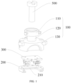
FIG. 1 is a first exploded view of a flat plate sample holder expansion structure used in a vacuum according to an embodiment of the present invention; -
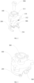
FIG. 2 is a second exploded view of the flat plate sample holder expansion structure used in the vacuum according to an embodiment of the present invention; -
FIG. 3 is a schematic assembly drawing of the flat plate sample holder expansion structure used in the vacuum according to an embodiment of the present invention; -
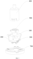
FIG. 4 is a first exploded view of the flat plate sample holder expansion structure used in the vacuum including a cylindrical sample holder gripper and a cylindrical sample holder locking base according to an embodiment of the present invention; -
FIG. 5 is a second exploded view of the flat plate sample holder expansion structure used in the vacuum including the cylindrical sample holder gripper and the cylindrical sample holder locking base according to an embodiment of the present invention; -
FIG. 6 is an assembly drawing of the flat plate sample holder expansion structure used in the vacuum according to an embodiment of the present invention, which shows the flat plate sample holder installed on the cylindrical sample holder locking base. -
- adapter
- 100
- head portion
- 110
- protruding rod
- 111
- neck portion
- 120
- rear portion
- 130
- locking ear
- 131
- notch
- 132
- flat plate sample holder tray
- 200
- stepped surface
- 210
- flat plate sample holder
- 300
- cylindrical sample holder gripper
- 400
- fastening element
- 500
- flat plate sample holder gripper
- 600
- cylindrical sample holder locking base
- 700
- In order to make the objectives, technical solutions and advantages of the present invention clearer, embodiments of the present invention will be further described in detail below with reference to the accompanying drawings.
- Referring to
FIGS. 1 to 4 , a flat plate sample holder expansion structure used in a vacuum includes anadapter 100 and a flat platesample holder tray 200; theadapter 100 is detachably attached to the flat platesample holder tray 200; a receiving space for fixing a flatplate sample holder 300 is provided between theadapter 100 and the flat platesample holder tray 200; the flatplate sample holder 300 is detachably and rigidly arranged in the receiving space; and theadapter 100 is capable of being detachably connected to a cylindricalsample holder gripper 400. The cylindricalsample holder gripper 400 is capable of clutching theadapter 100 and carrying the flatplate sample holder 300 to move through the detachably connection to theadapter 100. - Optionally, the receiving space may be formed only by the flat plate
sample holder tray 200, or may be formed by the flat platesample holder tray 200 together with theadapter 100, as long as the receiving space is large enough to receive the flatplate sample holder 300. - Referring to
FIGS. 1 ,2 and6 , in one of the embodiments, the flat plate sample holder expansion structure used in the vacuum further includes afastening element 500; the flat platesample holder tray 200 defines an opening, and the opening is configured to arrange and receive the flatplate sample holder 300, that is, the receiving space is formed by the opening defined by the flat platesample holder tray 200; and a steppedsurface 210 is disposed on a side wall of the opening and configured to support the flatplate sample holder 300. The stepped surface fits a contour of the flatplate sample holder 300, so as to support and position the flatplate sample holder 300. A flat platesample holder gripper 600 is capable of arranging the flatplate sample holder 300 on the steppedsurface 210 or detaching the flatplate sample holder 300 away from the steppedsurface 210. Theadapter 100 is approximate to an I-shaped structure. A through hole is defined in a center of the I-shaped structure, and the through hole penetrates through a head portion, a neck portion, and a rear portion of the I-shaped structure of theadapter 100. After the flatplate sample holder 300 is arranged on the steppedsurface 210, thefastening element 500 passes through the through hole and abuts on the flatplate sample holder 300. Under a joint action of the steppedsurface 210 and thefastening element 500, the flatplate sample holder 300 is fixed inside theadapter 100. - Optionally, the
fastening element 500 is a fastening screw, and the through hole is a threaded hole. After the flatplate sample holder 300 is arranged on the steppedsurface 210, the fastening screw is screwed into the threaded hole, and an end of the fastening screw abuts on the upper surface of the flatplate sample holder 300, so that the flatplate sample holder 300 is fixed between theadapter 100 and the flat platesample holder tray 200. The cylindricalsample holder gripper 400 can transfer the flatplate sample holder 300 by clutching theadapter 100. - Referring to
FIGS. 1 and2 , in one of the embodiments, the I-shaped structure includes thehead portion 110, theneck portion 120, and therear portion 130. Thehead portion 110 and therear portion 130 are fixedly connected to two ends of theneck portion 120, respectively. Thehead portion 110 is disc-shaped, and protrudingrods 111 are arranged on an outer side wall of the disc-shapedhead portion 110. The cylindricalsample holder gripper 400 is detachably connected to theadapter 100 by means of grasping the protrudingrods 111. - Optionally, the number of the protruding
rods 111 is three, and the three protrudingrods 111 are evenly arranged on the outer side wall of the disc-shapedhead portion 110. The cylindricalsample holder gripper 400 is provided with position locking components corresponding to the protrudingrods 111 respectively, and each position locking component includes an insertion part and a fastening part. After the protrudingrod 111 is inserted into the insertion part, the cylindricalsample holder gripper 400 is rotated to enable the protrudingrod 111 to enter the fastening part. After the fastening part fastens the protrudingrod 111, the cylindricalsample holder gripper 400 clutches theadapter 100 to move theadapter 100. - Referring to
FIG. 1 , in one of the embodiments, therear portion 130 of the I-shaped structure is cylindrical, and a top wall of the cylindricalrear portion 130 is fixedly connected to thehead portion 110 by means of theneck portion 120 of the I-shaped structure. Threaded holes are evenly arranged on the side wall of the cylindricalrear portion 130 and configured for the connection to the flat platesample holder tray 200, and threaded holes are also provided at corresponding positions on the flat platesample holder tray 200. The flat platesample holder tray 200 and the cylindricalrear portion 130 are fixedly connected together by means of threaded connection. - Referring to
FIGS. 2 ,4 and5 , in one of the embodiments, lockingears 131 extending outward in a radial direction are provided on the side wall of therear portion 130, and a cylindrical sampleholder locking base 700 is detachably connected to theadapter 100 by the lockingears 131. The cylindrical sampleholder locking base 700 defines locking grooves, and the lockingears 131 are locked into corresponding locking grooves, so that theadapter 100 is fixedly connected to the cylindrical sampleholder locking base 700. - Optionally, the number of the locking
ears 131 is three, and the three lockingears 131 are evenly distributed on the outer side wall of the cylindricalrear portion 130. Projections of each protrudingrod 111 and acorresponding locking ear 131, which are projected on a top surface of the cylindricalrear portion 130, are located in a radial straight line of the cylindricalrear portion 130. Specifically, the cylindricalsample holder gripper 400 clutches the three protrudingrods 111, and arranges theadapter 100 and the flat platesample holder tray 200, which carry the flatplate sample holder 300, on the cylindrical sampleholder locking base 700. Theadapter 100 and the flat platesample holder tray 200 are fixed on the cylindrical sampleholder locking base 700 when the three lockingears 131 are locked into the locking grooves of the cylindrical sampleholder locking base 700 respectively. - Referring to
FIG. 2 , in one of the embodiments, anotch 132 is provided on the side wall of therear portion 130 and located at a position corresponding to the opening defined by the flat platesample holder tray 200, and thenotch 132 is capable of receiving a front end of thesample holder gripper 600. The flat platesample holder gripper 600 extends into thenotch 132 to install and remove the flatplate sample holder 300. When the flat platesample holder gripper 600 is to install the flatplate sample holder 300 on the steppedsurface 210, thenotch 132 provides a space for the flat platesample holder gripper 600, thereby making it easier for the flat platesample holder gripper 600 to install the flatplate sample holder 300 on the steppedsurface 210. The flat platesample holder gripper 600 extends into thenotch 132 to detach the flatplate sample holder 300. - In one of the embodiments, materials of the
adapter 100 and the flat platesample holder tray 200 are non-magnetic, thermal conducting materials. - Referring to
FIGS. 1 to 6 , an operation process of transferring the flatplate sample holder 300 by means of the cylindricalsample holder gripper 400 is as follows. - The
adapter 100 and the flat platesample holder tray 200 are fixedly connected to form the receiving space for fixing the flatplate sample holder 300; the flat platesample holder gripper 600 installs the flatplate sample holder 300 into the receiving space; thefastening element 500 fastens the flatplate sample holder 300; the cylindricalsample holder gripper 400 clutches thehead portion 110 of theadapter 100 and adjusts positions and angles thereof; and theadapter 100 is installed on the cylindrical sampleholder locking base 700 and locked by therear portion 130 of theadapter 100. - In the flat plate sample holder expansion structure used in the vacuum above, the
adapter 100 is detachably attached to the flat platesample holder tray 200; the receiving space for receiving the flatplate sample holder 300 is provided between theadapter 100 and the flat platesample holder tray 200; the flatplate sample holder 300 is detachably arranged in the receiving space; the cylindricalsample holder gripper 400 is detachably connected to theadapter 100. The cylindricalsample holder gripper 400 transfers the flatplate sample holder 300 and the sample thereon to the low-temperature, high-intensity magnetic field apparatus, thereby achieving the objective of replacing samples in the vacuum environment, and providing key technical solutions for the platform built by combining multiple instruments.
Claims (8)
- A flat plate sample holder expansion structure for use in a vacuum, comprising an adapter (100), a flat plate sample holder tray (200) and a cylindrical sample holder gripper (400), wherein:the adapter (100) is configured to be detachably connected to the cylindrical sample holder gripper (400);the adapter (100) is futher configured to be detachably attached to the flat plate sample holder tray (200);a receiving space for receiving a flat plate sample holder (300) is formed between the adapter (100) and the flat plate sample holder tray (200); and the flat plate sample holder (300) is configured to be detachably and rigidly arranged in the receiving space; wherein the flat plate sample holder expansion structure for use in the vacuum further comprises a fastening element (500);characterized in that:the flat plate sample holder tray (200) comprises an opening, and a stepped surface (210) is formed on a side wall of the opening;the adapter (100) is substantially an I-shaped structure, and a through hole is formed in a center of the I-shaped structure;the fastening element (500) is configured to pass through the through hole, and to abut on the flat plate sample holder (300) after the flat plate sample holder (300) is installed on the stepped surface (210);a head portion (110) of the I-shaped structure is disc-shaped and further comprises protruding rods (111) arranged on an outer side wall of the disc-shaped head portion (110); and the cylindrical sample holder gripper (400) is configured to be detachably connected to the adapter (100) by the protruding rods (111);a rear portion (130) of the I-shaped structure is cylindrical, and threaded holes are evenly arranged in a side wall of the cylindrical rear portion (130) and configured to connect to the flat plate sample holder tray (200); and the rear portion (130) comprises furtherlocking ears (131) extending outward in a radial direction on the side wall of the rear portion (130), and wherein the flat sample holder expansion structure comprises furthera cylindrical sample holder locking base (700) which is configured to be detachably connected to the adapter (100) by the locking ears (131).
- The flat plate sample holder expansion structure for use in the vacuum according to claim 1, characterized in that the fastening element (500) is a fastening screw; the through hole is a threaded hole fitting the fastening screw; and the fastening screw is configured to be screwed into the threaded hole to abut on the flat plate sample holder (300).
- The flat plate sample holder expansion structure for use in the vacuum according to claim 1, characterized in that projections of each protruding rod (111) and its corresponding locking ear (131), which are projected on a top surface of the cylindrical rear portion (130), are located in a radial straight line on the cylindrical rear portion (130).
- The flat plate sample holder expansion structure for use in the vacuum according to claim 3, characterized in that a notch (132) is defined by the side wall of the rear portion (130) and located at a position corresponding to the opening defined by the flat plate sample holder tray (200); wherein the notch (132) is configured further to receive a front end of a flat plate sample holder gripper (600); and the flat plate sample holder gripper (600) is configured to extend into the notch (132) to install and remove the flat plate sample holder (300).
- The flat plate sample holder expansion structure for use in the vacuum according to claim 1, characterized in that the materials of the adapter (100) and the flat plate sample holder tray (200) are non-magnetic, thermal conducting materials.
- The flat plate sample holder expansion structure for use in the vacuum according to claim 1, characterized in that three protruding rods (111) are evenly arranged on the outer side wall of the disc-shaped head portion (110); the cylindrical sample holder gripper (400) is provided with position locking components corresponding to the protruding rods (111) respectively; and each position locking component comprises an insertion part and a fastening part.
- The flat plate sample holder expansion structure for use in the vacuum according to claim 1, characterized in that other threaded holes are provided at positions on the flat plate sample holder tray (200) corresponding to the threaded holes arranged in the side wall of the cylindrical rear portion (130) for fixedly connecting the flat plate sample holder tray (200) and the cylindrical rear portion (130) by means of threaded connection.
- The flat plate sample holder expansion structure for use in the vacuum according to claim 3, characterized in that the three locking ears (131) are evenly distributed on the outer side wall of the cylindrical rear portion (130).
Applications Claiming Priority (2)
| Application Number | Priority Date | Filing Date | Title |
|---|---|---|---|
| CN201810644266.8A CN110631764B (en) | 2018-06-21 | 2018-06-21 | Structure is extended to dull and stereotyped sample frame for vacuum |
| PCT/CN2018/092912 WO2019242032A1 (en) | 2018-06-21 | 2018-06-26 | Flat plate sample holder expanding structure for use in vacuum |
Publications (3)
| Publication Number | Publication Date |
|---|---|
| EP3812760A1 EP3812760A1 (en) | 2021-04-28 |
| EP3812760A4 EP3812760A4 (en) | 2021-08-18 |
| EP3812760B1 true EP3812760B1 (en) | 2023-09-27 |
Family
ID=68967612
Family Applications (1)
| Application Number | Title | Priority Date | Filing Date |
|---|---|---|---|
| EP18923278.8A Active EP3812760B1 (en) | 2018-06-21 | 2018-06-26 | Flat plate sample holder expanding structure for use in vacuum |
Country Status (4)
| Country | Link |
|---|---|
| US (1) | US12104996B2 (en) |
| EP (1) | EP3812760B1 (en) |
| CN (1) | CN110631764B (en) |
| WO (1) | WO2019242032A1 (en) |
Families Citing this family (2)
| Publication number | Priority date | Publication date | Assignee | Title |
|---|---|---|---|---|
| JP7181603B2 (en) * | 2019-08-16 | 2022-12-01 | 株式会社リガク | Sample holder for X-ray analysis |
| EP4012390A1 (en) * | 2020-12-11 | 2022-06-15 | Malvern Panalytical B.V. | Sample mounting system for an x-ray analysis apparatus |
Family Cites Families (16)
| Publication number | Priority date | Publication date | Assignee | Title |
|---|---|---|---|---|
| JP3553318B2 (en) * | 1997-05-20 | 2004-08-11 | 日本電子株式会社 | Holder holding device |
| DE102004053073B3 (en) * | 2004-11-03 | 2006-05-04 | Leica Mikrosysteme Gmbh | High pressure freezing device, automatic loading device for preparations in a high pressure freezing device and method for feeding a high pressure freezing device |
| JP4942180B2 (en) * | 2006-02-28 | 2012-05-30 | エスアイアイ・ナノテクノロジー株式会社 | Sample preparation equipment |
| CN102033055B (en) * | 2007-03-01 | 2013-05-29 | 浜松光子学株式会社 | Light detection device |
| WO2011014315A1 (en) * | 2009-07-31 | 2011-02-03 | Regents Of The University Of California | Scanning tunneling microscope assembly, reactor, and system |
| CN101846635B (en) * | 2010-05-07 | 2012-05-23 | 中国科学院半导体研究所 | Ultra-high vacuum multifunctional integrated test system |
| CN202041548U (en) * | 2011-05-05 | 2011-11-16 | 天津众通网络科技服务有限公司 | Sample table for temperature-change ultrahigh-vacuum tunnel scanning microscope |
| US8716683B2 (en) * | 2011-11-28 | 2014-05-06 | Jeol Ltd. | Ion beam processing system and sample processing method |
| KR101878753B1 (en) * | 2012-12-20 | 2018-07-16 | 삼성전자주식회사 | Sample stage used in microscopy for vertical loading and scanning probe microscopy using the same |
| US11187713B2 (en) * | 2013-01-14 | 2021-11-30 | Stratec Se | Laboratory module for storing and feeding to further processing of samples |
| CN203768483U (en) * | 2014-01-17 | 2014-08-13 | 中国科学院上海技术物理研究所 | Sample holder used for dipping type tellurium, cadmium and mercury liquid phase epitaxy |
| CN204374062U (en) * | 2015-01-14 | 2015-06-03 | 中国科学院物理研究所 | There is the ultrahigh vacuum Multi-example transfer device of spectral measurement function |
| JP6516569B2 (en) * | 2015-06-02 | 2019-05-22 | 株式会社日立ハイテクサイエンス | Scanning probe microscope |
| CN107664678B (en) * | 2017-09-12 | 2019-12-13 | 北京大学 | A low-vibration ultra-high vacuum low-temperature physical property measurement device |
| CN107677771B (en) * | 2017-09-15 | 2019-12-13 | 北京大学 | Ultra-high vacuum cryogenic sample stage |
| CN208547442U (en) * | 2018-06-21 | 2019-02-26 | 清华大学 | Vacuum flat samples frame prolongation structure |
-
2018
- 2018-06-21 CN CN201810644266.8A patent/CN110631764B/en active Active
- 2018-06-26 WO PCT/CN2018/092912 patent/WO2019242032A1/en not_active Ceased
- 2018-06-26 EP EP18923278.8A patent/EP3812760B1/en active Active
-
2020
- 2020-12-17 US US17/124,500 patent/US12104996B2/en active Active
Also Published As
| Publication number | Publication date |
|---|---|
| WO2019242032A1 (en) | 2019-12-26 |
| EP3812760A1 (en) | 2021-04-28 |
| US12104996B2 (en) | 2024-10-01 |
| CN110631764A (en) | 2019-12-31 |
| CN110631764B (en) | 2025-09-16 |
| EP3812760A4 (en) | 2021-08-18 |
| US20210102874A1 (en) | 2021-04-08 |
Similar Documents
| Publication | Publication Date | Title |
|---|---|---|
| US11041788B2 (en) | Cryotransfer system | |
| US5945607A (en) | Test specimen holder | |
| EP2555221B1 (en) | Method of studying a sample in an ETEM | |
| US10809211B2 (en) | Modular specimen holders for high pressure freezing and X-ray crystallography of a specimen | |
| EP1852888A1 (en) | Particle-optical apparatus with temperature switch | |
| JP6246113B2 (en) | Thermal analyzer | |
| US20100108907A1 (en) | Charged-particle optical system with dual loading options | |
| CN106537112A (en) | Loading station for transferring frozen samples at low temperatures | |
| EP3477680B1 (en) | Cryotransfer holder and workstation | |
| US11474009B2 (en) | Sample transfer apparatus and method for transferring a sample holder into and out of a vacuum chamber | |
| US12104996B2 (en) | Flat plate sample holder expansion structure used in vacuum | |
| US20020196023A1 (en) | NMR sample holder | |
| US20130120833A1 (en) | Microscope system | |
| EP2313717B1 (en) | Holder for a sample to be cooled to a low temperature in a vacuum space and 3he-4he dilution refrigerator adapted to accommodate such a holder | |
| EP0969484B1 (en) | Sample holder apparatus | |
| US8935811B2 (en) | Vertically mounted sample stage for microscopy and scanning probe microscope using the sample stage | |
| JP3123826B2 (en) | Sample cooling holder for electron microscope etc. | |
| US20160223803A1 (en) | Mounting device for a sample and method for removing a sample | |
| KR100478993B1 (en) | Microscope stand for a wafer inspection microscope | |
| EP1852889A2 (en) | Particle-optical apparatus with temperature switch | |
| US3171957A (en) | Specimen holder for an electron microscope with means to support a specimen across a thermocouple junction | |
| US3171956A (en) | Variant temperature environment for specimen stage of scientific instrument | |
| CN113758789A (en) | Apparatus and system for supporting heated metal samples | |
| WO2020105727A1 (en) | Sample holder unit for single-crystal x-ray structural analysis devices | |
| CN223527120U (en) | Clamping device, scanning electron microscope sample observation table and scanning electron microscope system |
Legal Events
| Date | Code | Title | Description |
|---|---|---|---|
| STAA | Information on the status of an ep patent application or granted ep patent |
Free format text: STATUS: THE INTERNATIONAL PUBLICATION HAS BEEN MADE |
|
| PUAI | Public reference made under article 153(3) epc to a published international application that has entered the european phase |
Free format text: ORIGINAL CODE: 0009012 |
|
| STAA | Information on the status of an ep patent application or granted ep patent |
Free format text: STATUS: REQUEST FOR EXAMINATION WAS MADE |
|
| 17P | Request for examination filed |
Effective date: 20210107 |
|
| AK | Designated contracting states |
Kind code of ref document: A1 Designated state(s): AL AT BE BG CH CY CZ DE DK EE ES FI FR GB GR HR HU IE IS IT LI LT LU LV MC MK MT NL NO PL PT RO RS SE SI SK SM TR |
|
| AX | Request for extension of the european patent |
Extension state: BA ME |
|
| A4 | Supplementary search report drawn up and despatched |
Effective date: 20210721 |
|
| RIC1 | Information provided on ipc code assigned before grant |
Ipc: G01N 23/2204 20180101ALI20210715BHEP Ipc: H01J 49/04 20060101ALI20210715BHEP Ipc: G01L 21/00 20060101ALI20210715BHEP Ipc: G01N 1/00 20060101ALI20210715BHEP Ipc: H01J 37/20 20060101ALI20210715BHEP Ipc: H01J 37/18 20060101ALI20210715BHEP Ipc: G01N 33/00 20060101AFI20210715BHEP |
|
| DAV | Request for validation of the european patent (deleted) | ||
| DAX | Request for extension of the european patent (deleted) | ||
| GRAP | Despatch of communication of intention to grant a patent |
Free format text: ORIGINAL CODE: EPIDOSNIGR1 |
|
| STAA | Information on the status of an ep patent application or granted ep patent |
Free format text: STATUS: GRANT OF PATENT IS INTENDED |
|
| INTG | Intention to grant announced |
Effective date: 20230424 |
|
| GRAS | Grant fee paid |
Free format text: ORIGINAL CODE: EPIDOSNIGR3 |
|
| GRAA | (expected) grant |
Free format text: ORIGINAL CODE: 0009210 |
|
| STAA | Information on the status of an ep patent application or granted ep patent |
Free format text: STATUS: THE PATENT HAS BEEN GRANTED |
|
| AK | Designated contracting states |
Kind code of ref document: B1 Designated state(s): AL AT BE BG CH CY CZ DE DK EE ES FI FR GB GR HR HU IE IS IT LI LT LU LV MC MK MT NL NO PL PT RO RS SE SI SK SM TR |
|
| REG | Reference to a national code |
Ref country code: GB Ref legal event code: FG4D |
|
| REG | Reference to a national code |
Ref country code: CH Ref legal event code: EP |
|
| REG | Reference to a national code |
Ref country code: DE Ref legal event code: R096 Ref document number: 602018058487 Country of ref document: DE |
|
| REG | Reference to a national code |
Ref country code: IE Ref legal event code: FG4D |
|
| REG | Reference to a national code |
Ref country code: LT Ref legal event code: MG9D |
|
| PG25 | Lapsed in a contracting state [announced via postgrant information from national office to epo] |
Ref country code: GR Free format text: LAPSE BECAUSE OF FAILURE TO SUBMIT A TRANSLATION OF THE DESCRIPTION OR TO PAY THE FEE WITHIN THE PRESCRIBED TIME-LIMIT Effective date: 20231228 |
|
| PG25 | Lapsed in a contracting state [announced via postgrant information from national office to epo] |
Ref country code: SE Free format text: LAPSE BECAUSE OF FAILURE TO SUBMIT A TRANSLATION OF THE DESCRIPTION OR TO PAY THE FEE WITHIN THE PRESCRIBED TIME-LIMIT Effective date: 20230927 Ref country code: RS Free format text: LAPSE BECAUSE OF FAILURE TO SUBMIT A TRANSLATION OF THE DESCRIPTION OR TO PAY THE FEE WITHIN THE PRESCRIBED TIME-LIMIT Effective date: 20230927 Ref country code: NO Free format text: LAPSE BECAUSE OF FAILURE TO SUBMIT A TRANSLATION OF THE DESCRIPTION OR TO PAY THE FEE WITHIN THE PRESCRIBED TIME-LIMIT Effective date: 20231227 Ref country code: LV Free format text: LAPSE BECAUSE OF FAILURE TO SUBMIT A TRANSLATION OF THE DESCRIPTION OR TO PAY THE FEE WITHIN THE PRESCRIBED TIME-LIMIT Effective date: 20230927 Ref country code: LT Free format text: LAPSE BECAUSE OF FAILURE TO SUBMIT A TRANSLATION OF THE DESCRIPTION OR TO PAY THE FEE WITHIN THE PRESCRIBED TIME-LIMIT Effective date: 20230927 Ref country code: HR Free format text: LAPSE BECAUSE OF FAILURE TO SUBMIT A TRANSLATION OF THE DESCRIPTION OR TO PAY THE FEE WITHIN THE PRESCRIBED TIME-LIMIT Effective date: 20230927 Ref country code: GR Free format text: LAPSE BECAUSE OF FAILURE TO SUBMIT A TRANSLATION OF THE DESCRIPTION OR TO PAY THE FEE WITHIN THE PRESCRIBED TIME-LIMIT Effective date: 20231228 Ref country code: FI Free format text: LAPSE BECAUSE OF FAILURE TO SUBMIT A TRANSLATION OF THE DESCRIPTION OR TO PAY THE FEE WITHIN THE PRESCRIBED TIME-LIMIT Effective date: 20230927 |
|
| REG | Reference to a national code |
Ref country code: NL Ref legal event code: MP Effective date: 20230927 |
|
| REG | Reference to a national code |
Ref country code: AT Ref legal event code: MK05 Ref document number: 1615887 Country of ref document: AT Kind code of ref document: T Effective date: 20230927 |
|
| PG25 | Lapsed in a contracting state [announced via postgrant information from national office to epo] |
Ref country code: NL Free format text: LAPSE BECAUSE OF FAILURE TO SUBMIT A TRANSLATION OF THE DESCRIPTION OR TO PAY THE FEE WITHIN THE PRESCRIBED TIME-LIMIT Effective date: 20230927 |
|
| PG25 | Lapsed in a contracting state [announced via postgrant information from national office to epo] |
Ref country code: IS Free format text: LAPSE BECAUSE OF FAILURE TO SUBMIT A TRANSLATION OF THE DESCRIPTION OR TO PAY THE FEE WITHIN THE PRESCRIBED TIME-LIMIT Effective date: 20240127 |
|
| PG25 | Lapsed in a contracting state [announced via postgrant information from national office to epo] |
Ref country code: AT Free format text: LAPSE BECAUSE OF FAILURE TO SUBMIT A TRANSLATION OF THE DESCRIPTION OR TO PAY THE FEE WITHIN THE PRESCRIBED TIME-LIMIT Effective date: 20230927 |
|
| PG25 | Lapsed in a contracting state [announced via postgrant information from national office to epo] |
Ref country code: ES Free format text: LAPSE BECAUSE OF FAILURE TO SUBMIT A TRANSLATION OF THE DESCRIPTION OR TO PAY THE FEE WITHIN THE PRESCRIBED TIME-LIMIT Effective date: 20230927 |
|
| PG25 | Lapsed in a contracting state [announced via postgrant information from national office to epo] |
Ref country code: SM Free format text: LAPSE BECAUSE OF FAILURE TO SUBMIT A TRANSLATION OF THE DESCRIPTION OR TO PAY THE FEE WITHIN THE PRESCRIBED TIME-LIMIT Effective date: 20230927 Ref country code: RO Free format text: LAPSE BECAUSE OF FAILURE TO SUBMIT A TRANSLATION OF THE DESCRIPTION OR TO PAY THE FEE WITHIN THE PRESCRIBED TIME-LIMIT Effective date: 20230927 Ref country code: IS Free format text: LAPSE BECAUSE OF FAILURE TO SUBMIT A TRANSLATION OF THE DESCRIPTION OR TO PAY THE FEE WITHIN THE PRESCRIBED TIME-LIMIT Effective date: 20240127 Ref country code: ES Free format text: LAPSE BECAUSE OF FAILURE TO SUBMIT A TRANSLATION OF THE DESCRIPTION OR TO PAY THE FEE WITHIN THE PRESCRIBED TIME-LIMIT Effective date: 20230927 Ref country code: EE Free format text: LAPSE BECAUSE OF FAILURE TO SUBMIT A TRANSLATION OF THE DESCRIPTION OR TO PAY THE FEE WITHIN THE PRESCRIBED TIME-LIMIT Effective date: 20230927 Ref country code: CZ Free format text: LAPSE BECAUSE OF FAILURE TO SUBMIT A TRANSLATION OF THE DESCRIPTION OR TO PAY THE FEE WITHIN THE PRESCRIBED TIME-LIMIT Effective date: 20230927 Ref country code: AT Free format text: LAPSE BECAUSE OF FAILURE TO SUBMIT A TRANSLATION OF THE DESCRIPTION OR TO PAY THE FEE WITHIN THE PRESCRIBED TIME-LIMIT Effective date: 20230927 Ref country code: SK Free format text: LAPSE BECAUSE OF FAILURE TO SUBMIT A TRANSLATION OF THE DESCRIPTION OR TO PAY THE FEE WITHIN THE PRESCRIBED TIME-LIMIT Effective date: 20230927 Ref country code: PT Free format text: LAPSE BECAUSE OF FAILURE TO SUBMIT A TRANSLATION OF THE DESCRIPTION OR TO PAY THE FEE WITHIN THE PRESCRIBED TIME-LIMIT Effective date: 20240129 |
|
| PG25 | Lapsed in a contracting state [announced via postgrant information from national office to epo] |
Ref country code: PL Free format text: LAPSE BECAUSE OF FAILURE TO SUBMIT A TRANSLATION OF THE DESCRIPTION OR TO PAY THE FEE WITHIN THE PRESCRIBED TIME-LIMIT Effective date: 20230927 Ref country code: IT Free format text: LAPSE BECAUSE OF FAILURE TO SUBMIT A TRANSLATION OF THE DESCRIPTION OR TO PAY THE FEE WITHIN THE PRESCRIBED TIME-LIMIT Effective date: 20230927 |
|
| REG | Reference to a national code |
Ref country code: DE Ref legal event code: R097 Ref document number: 602018058487 Country of ref document: DE |
|
| PG25 | Lapsed in a contracting state [announced via postgrant information from national office to epo] |
Ref country code: DK Free format text: LAPSE BECAUSE OF FAILURE TO SUBMIT A TRANSLATION OF THE DESCRIPTION OR TO PAY THE FEE WITHIN THE PRESCRIBED TIME-LIMIT Effective date: 20230927 |
|
| PG25 | Lapsed in a contracting state [announced via postgrant information from national office to epo] |
Ref country code: DK Free format text: LAPSE BECAUSE OF FAILURE TO SUBMIT A TRANSLATION OF THE DESCRIPTION OR TO PAY THE FEE WITHIN THE PRESCRIBED TIME-LIMIT Effective date: 20230927 |
|
| PLBE | No opposition filed within time limit |
Free format text: ORIGINAL CODE: 0009261 |
|
| STAA | Information on the status of an ep patent application or granted ep patent |
Free format text: STATUS: NO OPPOSITION FILED WITHIN TIME LIMIT |
|
| 26N | No opposition filed |
Effective date: 20240628 |
|
| PG25 | Lapsed in a contracting state [announced via postgrant information from national office to epo] |
Ref country code: SI Free format text: LAPSE BECAUSE OF FAILURE TO SUBMIT A TRANSLATION OF THE DESCRIPTION OR TO PAY THE FEE WITHIN THE PRESCRIBED TIME-LIMIT Effective date: 20230927 |
|
| PG25 | Lapsed in a contracting state [announced via postgrant information from national office to epo] |
Ref country code: SI Free format text: LAPSE BECAUSE OF FAILURE TO SUBMIT A TRANSLATION OF THE DESCRIPTION OR TO PAY THE FEE WITHIN THE PRESCRIBED TIME-LIMIT Effective date: 20230927 |
|
| PG25 | Lapsed in a contracting state [announced via postgrant information from national office to epo] |
Ref country code: BG Free format text: LAPSE BECAUSE OF FAILURE TO SUBMIT A TRANSLATION OF THE DESCRIPTION OR TO PAY THE FEE WITHIN THE PRESCRIBED TIME-LIMIT Effective date: 20230927 |
|
| PG25 | Lapsed in a contracting state [announced via postgrant information from national office to epo] |
Ref country code: BG Free format text: LAPSE BECAUSE OF FAILURE TO SUBMIT A TRANSLATION OF THE DESCRIPTION OR TO PAY THE FEE WITHIN THE PRESCRIBED TIME-LIMIT Effective date: 20230927 |
|
| PG25 | Lapsed in a contracting state [announced via postgrant information from national office to epo] |
Ref country code: MC Free format text: LAPSE BECAUSE OF FAILURE TO SUBMIT A TRANSLATION OF THE DESCRIPTION OR TO PAY THE FEE WITHIN THE PRESCRIBED TIME-LIMIT Effective date: 20230927 |
|
| REG | Reference to a national code |
Ref country code: CH Ref legal event code: PL |
|
| PG25 | Lapsed in a contracting state [announced via postgrant information from national office to epo] |
Ref country code: LU Free format text: LAPSE BECAUSE OF NON-PAYMENT OF DUE FEES Effective date: 20240626 |
|
| PG25 | Lapsed in a contracting state [announced via postgrant information from national office to epo] |
Ref country code: IE Free format text: LAPSE BECAUSE OF NON-PAYMENT OF DUE FEES Effective date: 20240626 |
|
| PG25 | Lapsed in a contracting state [announced via postgrant information from national office to epo] |
Ref country code: BE Free format text: LAPSE BECAUSE OF NON-PAYMENT OF DUE FEES Effective date: 20240630 Ref country code: CH Free format text: LAPSE BECAUSE OF NON-PAYMENT OF DUE FEES Effective date: 20240630 |
|
| REG | Reference to a national code |
Ref country code: BE Ref legal event code: MM Effective date: 20240630 |
|
| PGFP | Annual fee paid to national office [announced via postgrant information from national office to epo] |
Ref country code: GB Payment date: 20250627 Year of fee payment: 8 |
|
| PGFP | Annual fee paid to national office [announced via postgrant information from national office to epo] |
Ref country code: FR Payment date: 20250627 Year of fee payment: 8 |
|
| PGFP | Annual fee paid to national office [announced via postgrant information from national office to epo] |
Ref country code: DE Payment date: 20250627 Year of fee payment: 8 |
|
| PG25 | Lapsed in a contracting state [announced via postgrant information from national office to epo] |
Ref country code: CY Free format text: LAPSE BECAUSE OF FAILURE TO SUBMIT A TRANSLATION OF THE DESCRIPTION OR TO PAY THE FEE WITHIN THE PRESCRIBED TIME-LIMIT; INVALID AB INITIO Effective date: 20180626 |
|
| PG25 | Lapsed in a contracting state [announced via postgrant information from national office to epo] |
Ref country code: HU Free format text: LAPSE BECAUSE OF FAILURE TO SUBMIT A TRANSLATION OF THE DESCRIPTION OR TO PAY THE FEE WITHIN THE PRESCRIBED TIME-LIMIT; INVALID AB INITIO Effective date: 20180626 |