EP3812695A1 - Gauge - Google Patents
Gauge Download PDFInfo
- Publication number
- EP3812695A1 EP3812695A1 EP20201244.9A EP20201244A EP3812695A1 EP 3812695 A1 EP3812695 A1 EP 3812695A1 EP 20201244 A EP20201244 A EP 20201244A EP 3812695 A1 EP3812695 A1 EP 3812695A1
- Authority
- EP
- European Patent Office
- Prior art keywords
- head
- gauge
- rod
- portions
- configuration
- Prior art date
- Legal status (The legal status is an assumption and is not a legal conclusion. Google has not performed a legal analysis and makes no representation as to the accuracy of the status listed.)
- Withdrawn
Links
- 238000007689 inspection Methods 0.000 claims abstract description 45
- 238000003780 insertion Methods 0.000 claims abstract description 25
- 230000037431 insertion Effects 0.000 claims abstract description 25
- 238000000034 method Methods 0.000 claims abstract description 18
- 238000005259 measurement Methods 0.000 description 7
- 239000011324 bead Substances 0.000 description 4
- 238000003908 quality control method Methods 0.000 description 3
- 238000006243 chemical reaction Methods 0.000 description 1
- 238000002591 computed tomography Methods 0.000 description 1
- 230000001066 destructive effect Effects 0.000 description 1
- 238000012986 modification Methods 0.000 description 1
- 230000004048 modification Effects 0.000 description 1
- 238000009877 rendering Methods 0.000 description 1
Images


Classifications
-
- G—PHYSICS
- G01—MEASURING; TESTING
- G01B—MEASURING LENGTH, THICKNESS OR SIMILAR LINEAR DIMENSIONS; MEASURING ANGLES; MEASURING AREAS; MEASURING IRREGULARITIES OF SURFACES OR CONTOURS
- G01B3/00—Measuring instruments characterised by the use of mechanical techniques
- G01B3/46—Plug gauges for internal dimensions with engaging surfaces which are at a fixed distance, although they may be preadjustable
- G01B3/50—Plug gauges for internal dimensions with engaging surfaces which are at a fixed distance, although they may be preadjustable of limit-gauge type, i.e. "go/no-go"
-
- G—PHYSICS
- G01—MEASURING; TESTING
- G01B—MEASURING LENGTH, THICKNESS OR SIMILAR LINEAR DIMENSIONS; MEASURING ANGLES; MEASURING AREAS; MEASURING IRREGULARITIES OF SURFACES OR CONTOURS
- G01B3/00—Measuring instruments characterised by the use of mechanical techniques
- G01B3/46—Plug gauges for internal dimensions with engaging surfaces which are at a fixed distance, although they may be preadjustable
-
- F—MECHANICAL ENGINEERING; LIGHTING; HEATING; WEAPONS; BLASTING
- F02—COMBUSTION ENGINES; HOT-GAS OR COMBUSTION-PRODUCT ENGINE PLANTS
- F02C—GAS-TURBINE PLANTS; AIR INTAKES FOR JET-PROPULSION PLANTS; CONTROLLING FUEL SUPPLY IN AIR-BREATHING JET-PROPULSION PLANTS
- F02C7/00—Features, components parts, details or accessories, not provided for in, or of interest apart form groups F02C1/00 - F02C6/00; Air intakes for jet-propulsion plants
Definitions
- the present disclosure relates to a gauge and in particular to a gauge for assessing the internal dimensions of a component.
- the present disclosure also relates to a method of using the gauge to assess the internal dimensions of a component, e.g. a gas turbine engine component.
- known go/no go plug gauges are used to measure the internal dimensions of a bore and typically comprise a rod having cylindrical plugs at opposing ends.
- One of the plugs (the 'go' plug) is of a smaller diameter than the other (the 'no go' plug).
- the 'go' plug must fit into the bore and the 'no go' plug must not fit into the bore for the component to pass the quality control test. If the portion of the bore requiring measurement is beyond a restriction, such a go/no gauge cannot be used as the both plugs will be prevented from passing the restriction.
- known sprung internal bore callipers cannot easily access internal dimensions of complex components and, furthermore, can only provide local point measurements thus necessitating multiple point measurements in order to ensure full assessment of the internal dimension.
- Nozzle guide vane vents and scavenge oil pipes are examples of gas turbine engine components that present difficulties in such quality control processes. These pipes include weld beads and checking the maximum dimensions of the weld bead and thus the minimum area of the pipe is hampered by restrictions in the pipe geometry.
- An improved method for measuring internal dimensions of a component e.g. a gas turbine engine component such as a nozzle guide vane vent and scavenge oil pipe is needed.
- the present disclosure provides a gauge and a method of measuring an internal dimension of a bore within a component, as set out in the appended claims.
- a gauge comprising an elongate rod and a head; the rod has an elongate axis; the head has a transverse dimension perpendicular to the elongate axis of the rod; and the gauge has an insertion configuration and an inspection configuration, wherein the transverse dimension of the head is greater in the inspection configuration than in the insertion configuration; characterised in that the head comprises two head portions each with a longitudinally-extending outer surface and a longitudinally-extending inner surface and, in the insertion configuration, the inner surfaces of the head portions are at least partly in abutment with each other.
- the head can pass a restricted portion within a bore within a component (e.g. a bore within an vent and oil scavenge pipe) and then be expanded to the inspection configuration to ensure that the portion of the bore beyond the restriction meets the minimum required dimension (cross-sectional area) required for effective operation of the component.
- a component e.g. a bore within an vent and oil scavenge pipe
- the outer surfaces may be chamfered towards an end face of the head (distal the rod) to prevent the end faces snagging on the weld bead geometry or surface to be measured.
- the outer surfaces may additionally or alternatively be chamfered towards the rod.
- the outer surfaces may be at least partly curved such that the head has a circular or oval or obround end face at least in the insertion configuration.
- the outer surface of each head portion may have a curved end portion and substantially planar front and rear portions, the front and rear portions being spaced by the inner surface.
- the two head portions may be symmetrical head portions.
- the inner surfaces of the head portions may be spaced from each other in a transverse direction (perpendicular to the elongate axis of the rod) in the inspection configuration. This spacing increases the transverse dimension of the head in the inspection configuration.
- the gauge further comprises an insert for spacing the inner surfaces of the head portions in the inspection configuration.
- a transverse dimension of the rod (perpendicular to the elongate axis of the rod) is greater in the inspection configuration than in the insertion configuration.
- the rod comprises two rod portions e.g. two symmetrical rod portions each with a longitudinally-extending outer surface and longitudinally-extending inner surface.
- the inner surfaces of the rod portions are at least partly in abutment with each other.
- the inner surfaces of the rod portions may be spaced from each other in a transverse direction in the inspection configuration.
- the insert is an elongate insert and spaces both the inner surfaces of the head portions and the inner surfaces of the rod portions in the inspection configuration.
- each head portion is integrally formed with a respective rod portion.
- the inner surfaces of the head portions are each continuous with the inner surface of the respective rod portion.
- the inner surface of the head/rod portions define a bore (e.g. a central/axial bore) therebetween in the insertion configuration for receiving the insert for conversion to the inspection configuration.
- each head/rod portion may comprise an elongate channel e.g. a centrally disposed elongate channel, the opposing channels abutting to form the bore e.g. the central bore through the head and elongate rod.
- Each channel may have a v-shaped transverse profile (perpendicular to the elongate axis of the channel). Where the channels are v-shaped, the (central) bore will have a substantially square transverse profile.
- the insert e.g. the elongate insert may have opposing longitudinally-extending transverse surfaces which, in the inspection configuration abut the inner surfaces of the head/rod portions.
- the insert may also have opposing front and rear surfaces (spacing the transverse surfaces).
- the front and rear surfaces may be chamfered towards an end face of the insert (proximal the head) to prevent the end faces snagging on the weld bead or surface to be measured.
- the front and rear surfaces may additionally/alternatively be chamfered towards the rod.
- Each transverse surface of the insert may have an elongate ridge e.g. a centrally disposed elongate ridge. It may have a v-shaped transverse profile (perpendicular to the elongate axis of the ridge).
- the opposing ridges may be received in the channels on the inner surfaces of the head/rod portions. This assists with alignment of the insert between the head/rod portions.
- the front and rear surfaces of the insert may be flush with the outer surfaces of the head portions (e.g. with the front and rear portions of the outer surfaces of the head portions) and may extend the perimeter/transverse dimension of the head.
- a method of measuring an internal dimension of a bore in a component comprising the steps of: providing a gauge according to the first aspect in the insertion configuration of the gauge; inserting the gauge into the bore until the head is positioned at the position to be inspected; converting the gauge to its inspection configuration; and determining if the position of the bore to be inspected has a greater dimension than the transverse dimension of the head.
- converting the gauge to its inspection configuration comprises moving the inner surfaces of the head portions from abutment with each other such that they are spaced from each other in a transverse dimension.
- the method comprises providing a gauge further comprising an insert and converting the gauge to its inspection configuration comprises spacing the inner surfaces of the head portions with the insert.
- method comprises providing the inner surface of each head portion with an elongate channel and providing the insert with opposing longitudinally-extending transverse surfaces each having an elongate ridge and wherein converting the gauge to its inspection configuration comprises seating the opposing ridges within the channels on the inner surfaces of the head portions.
- the bore is a bore within a gas turbine engine component.
- the gas turbine engine component may be a nozzle guide vane vent and scavenge oil pipe.
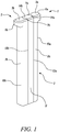
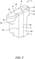
- Figures 1 and 2 show perspective views of a gauge 1 in the inspection configuration.
- the gauge comprises an elongate rod 2 and a head 3 having a transverse dimension perpendicular to the elongate axis of the rod 2.
- the head 3 has a larger transverse dimension than the rod 2.
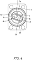
- the gauge 1 has an inspection configuration (shown in Figures 1 to 3 & 5 ) wherein the transverse dimension (and the perimeter) of the head 3 is greater than in an insertion configuration shown in Figure 4 .
- the gauge 1 allows insertion of the gauge 1 into a bore 4 of a gas turbine component 5 (e.g. a low pressure nozzle guide vane vent and oil scavenge pipe) in its reduced size insertion configuration (as shown in Figure 4 ) so that the head 3 can pass any restriction 15 within the bore 4.
- a gas turbine component 5 e.g. a low pressure nozzle guide vane vent and oil scavenge pipe
- the gauge 1 can be converted to its inspection configuration (as shown in Figures 3 and 4 ) to ensure that the bore 4 (at the position to be measured) meets the minimum dimension requirements matching the (larger) transverse dimension of the head 3 in the inspection configuration.
- the head 3 comprises two symmetrical head portions 3a, 3b each with a longitudinally-extending outer surface 6a, 6b and longitudinally-extending inner surface 7a, 7b.
- the outer surfaces 6a, 6b have curved end portions and substantially planar front/rear portions such that the head 3 has an obround end face.
- Each inner surface 7a, 7b comprises an elongate v-shaped channel 8a, 8b that is centrally disposed i.e. equally spaced from the front/rear portions of the respective outer surfaces 6a, 6b.
- the inner surfaces 7a, 7b of the head portions 3a, 3b are partly in abutment with each other with the elongate channels 8a, 8b aligned such that a central bore 9 (having a square transverse profile) is provided within the gauge 1.
- the rod 2 also comprises two symmetrical rod portions 2a, 2b each with a longitudinally-extending outer surface 10a, 10b and longitudinally-extending inner surface with a centrally disposed v-shaped channel (not shown) that is continuous with the elongate channels 8a, 8b of the head portions 3a, 3b.
- the central bore 9 extends through both the head 3 and rod 2.
- the inner surfaces 7a, 7b of the head portions 3a, 3b and the inner surfaces of the rod portions 2a, 3b are spaced from each other in a transverse dimension by an elongate insert 11.
- the insert 11 has opposing longitudinally-extending transverse surfaces 12a, 12b which, in the inspection configuration abut the inner surfaces 7a, 7b of the head portions 3a, 3b and rod portions 2a, 2b.
- the insert also comprises outer front/rear surfaces 13a, 13b which are flush with the outer surfaces 6a, 6b of the head portions 3a, 3b and the rod portions 2a, 2b in the inspection configuration.
- the outer front/rear surfaces 13a, 13b of the insert and the outer surfaces 6a, 6b of the head portions 3a, 3b are chamfered towards the end face of the head 3 and also towards the rod 2.
- Each transverse surface 12a, 12b of the insert 11 (abutting the inner surfaces 7a, 7b of the head portions 3a, 3b in the inspection configuration) has a centrally disposed elongate v-shaped ridge 14a, 14b which is equidistant from each of the outer front/rear surfaces 13a, 13b of the insert 11.
- the insert 11 is inserted into the central bore 9 such that the ridges 14a, 14b are received in the channels 8a, 8b on the inner surfaces 7a, 7b of the head portions 3a, 3b and rod portions 2a, 2b.
- the v-shaped profiles ensure the correct alignment of the insert 11 within the central bore 9 so that the outer (front/rear) surfaces 13a, 13b are flush with the outer surfaces 6a, 6b of the head portions 2a, 2b.
- the outer (front/rear) surfaces 13a, 13b of the insert 11 extend the transverse dimension and the perimeter of the head 3 in the inspection configuration to the minimum dimension required for the bore of the component to pass the inspection criteria.
Landscapes
- Physics & Mathematics (AREA)
- General Physics & Mathematics (AREA)
- Length-Measuring Instruments Using Mechanical Means (AREA)
- A Measuring Device Byusing Mechanical Method (AREA)
Abstract
A gauge comprising an elongate rod and a head. The rod has an elongate axis. The head has a transverse dimension perpendicular to the elongate axis of the rod. The gauge has an insertion configuration and an inspection configuration, wherein the transverse dimension of the head is greater in the inspection configuration than in the insertion configuration. The head comprises two head portions each with a longitudinally-extending outer surface and a longitudinally-extending inner surface and, in the insertion configuration, the inner surfaces of the head portions are at least partly in abutment with each other. The gauge can be used in a method of measuring an internal dimension of a bore within a component.
Description
- The present disclosure relates to a gauge and in particular to a gauge for assessing the internal dimensions of a component. The present disclosure also relates to a method of using the gauge to assess the internal dimensions of a component, e.g. a gas turbine engine component.
- There is often the need to measure the internal dimensions of a component e.g. to ensure that the dimensions are within acceptable tolerances. This quality control is essential to ensure optimum and/or safe performance of the component.
- Such measurement of internal dimensions can be problematic where the component has a complex geometry rendering the internal dimension inaccessible. In particular, where access to the internal dimension for measurement is limited by a restricted portion (having reduced dimensions), use of many of the known gauges may be prevented.
- For example, known go/no go plug gauges are used to measure the internal dimensions of a bore and typically comprise a rod having cylindrical plugs at opposing ends. One of the plugs (the 'go' plug) is of a smaller diameter than the other (the 'no go' plug). The 'go' plug must fit into the bore and the 'no go' plug must not fit into the bore for the component to pass the quality control test. If the portion of the bore requiring measurement is beyond a restriction, such a go/no gauge cannot be used as the both plugs will be prevented from passing the restriction.
- Similarly, known sprung internal bore callipers cannot easily access internal dimensions of complex components and, furthermore, can only provide local point measurements thus necessitating multiple point measurements in order to ensure full assessment of the internal dimension.
- Whilst known methods such as CT scanning and flow measurement can be used where access is restricted, these methods are time consuming and costly.
- Destructive methods where sacrificial components are destroyed during measurement are wasteful.
- It is critical that internal dimensions of gas turbine components meet predefined requirements for safe and optimum performance of the gas turbine engine. Nozzle guide vane vents and scavenge oil pipes are examples of gas turbine engine components that present difficulties in such quality control processes. These pipes include weld beads and checking the maximum dimensions of the weld bead and thus the minimum area of the pipe is hampered by restrictions in the pipe geometry.
- An improved method for measuring internal dimensions of a component e.g. a gas turbine engine component such as a nozzle guide vane vent and scavenge oil pipe is needed.
- The present disclosure provides a gauge and a method of measuring an internal dimension of a bore within a component, as set out in the appended claims.
- According to a first aspect of the disclosure there is provided a gauge comprising an elongate rod and a head; the rod has an elongate axis; the head has a transverse dimension perpendicular to the elongate axis of the rod; and the gauge has an insertion configuration and an inspection configuration, wherein the transverse dimension of the head is greater in the inspection configuration than in the insertion configuration; characterised in that the head comprises two head portions each with a longitudinally-extending outer surface and a longitudinally-extending inner surface and, in the insertion configuration, the inner surfaces of the head portions are at least partly in abutment with each other.
- By providing a gauge having a head that has a reduced transverse dimension in an insertion configuration, the head can pass a restricted portion within a bore within a component (e.g. a bore within an vent and oil scavenge pipe) and then be expanded to the inspection configuration to ensure that the portion of the bore beyond the restriction meets the minimum required dimension (cross-sectional area) required for effective operation of the component.
- The outer surfaces may be chamfered towards an end face of the head (distal the rod) to prevent the end faces snagging on the weld bead geometry or surface to be measured. The outer surfaces may additionally or alternatively be chamfered towards the rod.
- The outer surfaces may be at least partly curved such that the head has a circular or oval or obround end face at least in the insertion configuration. For example, the outer surface of each head portion may have a curved end portion and substantially planar front and rear portions, the front and rear portions being spaced by the inner surface.
- The two head portions may be symmetrical head portions.
- The inner surfaces of the head portions may be spaced from each other in a transverse direction (perpendicular to the elongate axis of the rod) in the inspection configuration. This spacing increases the transverse dimension of the head in the inspection configuration.
- In some embodiments, the gauge further comprises an insert for spacing the inner surfaces of the head portions in the inspection configuration.
- In some embodiments, a transverse dimension of the rod (perpendicular to the elongate axis of the rod) is greater in the inspection configuration than in the insertion configuration.
- In some embodiments, the rod comprises two rod portions e.g. two symmetrical rod portions each with a longitudinally-extending outer surface and longitudinally-extending inner surface. In the insertion configuration, the inner surfaces of the rod portions are at least partly in abutment with each other.
- Where the rod comprises two rod portions e.g. two symmetrical rod portions, the inner surfaces of the rod portions may be spaced from each other in a transverse direction in the inspection configuration.
- In some embodiments, the insert is an elongate insert and spaces both the inner surfaces of the head portions and the inner surfaces of the rod portions in the inspection configuration.
- In some embodiments, each head portion is integrally formed with a respective rod portion. In these embodiments, the inner surfaces of the head portions are each continuous with the inner surface of the respective rod portion.
- In some embodiments, the inner surface of the head/rod portions define a bore (e.g. a central/axial bore) therebetween in the insertion configuration for receiving the insert for conversion to the inspection configuration.
- The inner surface of each head/rod portion may comprise an elongate channel e.g. a centrally disposed elongate channel, the opposing channels abutting to form the bore e.g. the central bore through the head and elongate rod. Each channel may have a v-shaped transverse profile (perpendicular to the elongate axis of the channel). Where the channels are v-shaped, the (central) bore will have a substantially square transverse profile.
- The insert, e.g. the elongate insert may have opposing longitudinally-extending transverse surfaces which, in the inspection configuration abut the inner surfaces of the head/rod portions. The insert may also have opposing front and rear surfaces (spacing the transverse surfaces). The front and rear surfaces may be chamfered towards an end face of the insert (proximal the head) to prevent the end faces snagging on the weld bead or surface to be measured. The front and rear surfaces may additionally/alternatively be chamfered towards the rod.
- Each transverse surface of the insert may have an elongate ridge e.g. a centrally disposed elongate ridge. It may have a v-shaped transverse profile (perpendicular to the elongate axis of the ridge). Thus in the inspection configuration, the opposing ridges may be received in the channels on the inner surfaces of the head/rod portions. This assists with alignment of the insert between the head/rod portions.
- Upon insertion of the insert to convert the gauge to the inspection configuration, the front and rear surfaces of the insert may be flush with the outer surfaces of the head portions (e.g. with the front and rear portions of the outer surfaces of the head portions) and may extend the perimeter/transverse dimension of the head.
- In a second aspect of the disclosure, there is provided a method of measuring an internal dimension of a bore in a component, the method comprising the steps of: providing a gauge according to the first aspect in the insertion configuration of the gauge; inserting the gauge into the bore until the head is positioned at the position to be inspected; converting the gauge to its inspection configuration; and determining if the position of the bore to be inspected has a greater dimension than the transverse dimension of the head.
- In some embodiments, converting the gauge to its inspection configuration comprises moving the inner surfaces of the head portions from abutment with each other such that they are spaced from each other in a transverse dimension.
- In some embodiments, the method comprises providing a gauge further comprising an insert and converting the gauge to its inspection configuration comprises spacing the inner surfaces of the head portions with the insert.
- In some embodiments, method comprises providing the inner surface of each head portion with an elongate channel and providing the insert with opposing longitudinally-extending transverse surfaces each having an elongate ridge and wherein converting the gauge to its inspection configuration comprises seating the opposing ridges within the channels on the inner surfaces of the head portions.
- In some embodiments, the bore is a bore within a gas turbine engine component. The gas turbine engine component may be a nozzle guide vane vent and scavenge oil pipe.
- The skilled person will appreciate that except where mutually exclusive, a feature or parameter described in relation to any one of the above aspects may be applied to any other aspect. Except where mutually exclusive, any of the features may be employed separately or in combination with any other features and the disclosure extends to and includes all combinations and sub-combinations of one or more features described herein.
- Embodiments will now be described by way of example only, with reference to the Figures, in which:
-
Figure 1 is perspective view of the gauge in the inspection configuration; -
Figure 2 is a perspective view of the head of the gauge in the inspection configuration; and -
Figure 3 is a top view of the gauge within a component bore in the inspection configuration; -
Figure 4 is a top view of the gauge within a component bore in the insertion configuration; and -
Figure 5 is a section view of the gauge within a component bore in the inspection configuration showing the head passing beyond the restriction. - Aspects and embodiments of the present disclosure will now be discussed with reference to the accompanying figures. Further aspects and embodiments will be apparent to those skilled in the art.
-
Figures 1 and2 show perspective views of agauge 1 in the inspection configuration. - The gauge comprises an
elongate rod 2 and ahead 3 having a transverse dimension perpendicular to the elongate axis of therod 2. Thehead 3 has a larger transverse dimension than therod 2. - The
gauge 1 has an inspection configuration (shown inFigures 1 to 3 &5 ) wherein the transverse dimension (and the perimeter) of thehead 3 is greater than in an insertion configuration shown inFigure 4 . - This allows insertion of the
gauge 1 into abore 4 of a gas turbine component 5 (e.g. a low pressure nozzle guide vane vent and oil scavenge pipe) in its reduced size insertion configuration (as shown inFigure 4 ) so that thehead 3 can pass anyrestriction 15 within thebore 4. Once the restriction has been passed, thegauge 1 can be converted to its inspection configuration (as shown inFigures 3 and4 ) to ensure that the bore 4 (at the position to be measured) meets the minimum dimension requirements matching the (larger) transverse dimension of thehead 3 in the inspection configuration. - The
head 3 comprises twosymmetrical head portions 3a, 3b each with a longitudinally-extendingouter surface inner surface 7a, 7b. - The
outer surfaces head 3 has an obround end face. - Each
inner surface 7a, 7b comprises an elongate v-shapedchannel 8a, 8b that is centrally disposed i.e. equally spaced from the front/rear portions of the respectiveouter surfaces - In the insertion configuration (
Figure 4 ), theinner surfaces 7a, 7b of thehead portions 3a, 3b are partly in abutment with each other with theelongate channels 8a, 8b aligned such that a central bore 9 (having a square transverse profile) is provided within thegauge 1. - The
rod 2 also comprises twosymmetrical rod portions 2a, 2b each with a longitudinally-extendingouter surface elongate channels 8a, 8b of thehead portions 3a, 3b. - Accordingly, the
central bore 9 extends through both thehead 3 androd 2. - In the inspection configuration, the
inner surfaces 7a, 7b of thehead portions 3a, 3b and the inner surfaces of therod portions 2a, 3b are spaced from each other in a transverse dimension by anelongate insert 11. - The
insert 11 has opposing longitudinally-extendingtransverse surfaces 12a, 12b which, in the inspection configuration abut theinner surfaces 7a, 7b of thehead portions 3a, 3b androd portions 2a, 2b. - The insert also comprises outer front/
rear surfaces 13a, 13b which are flush with theouter surfaces head portions 3a, 3b and therod portions 2a, 2b in the inspection configuration. The outer front/rear surfaces 13a, 13b of the insert and theouter surfaces head portions 3a, 3b are chamfered towards the end face of thehead 3 and also towards therod 2. - Each
transverse surface 12a, 12b of the insert 11 (abutting theinner surfaces 7a, 7b of thehead portions 3a, 3b in the inspection configuration) has a centrally disposed elongate v-shapedridge rear surfaces 13a, 13b of theinsert 11. - To convert the
gauge 1 from the insertion configuration (Figure 4 ) to the inspection configuration (Figure 3 ) within the bore, theinsert 11 is inserted into thecentral bore 9 such that theridges channels 8a, 8b on theinner surfaces 7a, 7b of thehead portions 3a, 3b androd portions 2a, 2b. The v-shaped profiles ensure the correct alignment of theinsert 11 within thecentral bore 9 so that the outer (front/rear) surfaces 13a, 13b are flush with theouter surfaces head portions 2a, 2b. - The outer (front/rear) surfaces 13a, 13b of the
insert 11 extend the transverse dimension and the perimeter of thehead 3 in the inspection configuration to the minimum dimension required for the bore of the component to pass the inspection criteria. - It will be understood that the disclosure is not limited to the embodiments above-described and various modifications and improvements can be made without departing from the concepts described herein within the scope of the following claims.
Claims (15)
- A gauge (1) comprising an elongate rod (2) and a head (3);
the rod (2) has an elongate axis;
the head has a transverse dimension perpendicular to the elongate axis of the rod (2); and the gauge has an insertion configuration and an inspection configuration, wherein the transverse dimension of the head (3) is greater in the inspection configuration than in the insertion configuration;
characterised in that the head (3) comprises two head portions (3a, 3b) each with a longitudinally-extending outer surface (6a, 6b) and a longitudinally-extending inner surface (7a, 7b) and, in the insertion configuration, the inner surfaces (7a, 7b) of the head portions (3a, 3b) are at least partly in abutment with each other. - The gauge of Claim 1, wherein in the inspection configuration, the inner surfaces (7a, 7b) of the head portions (3a, 3b) are spaced from each other in a transverse direction.
- The gauge of Claim 1 or 2, wherein a transverse dimension of the rod (2) is greater in the inspection configuration than in the insertion configuration.
- The gauge of Claim 3, wherein the rod (2) comprises two rod portions (2a, 2b) each with a longitudinally-extending outer surface (10a, 10b) and longitudinally-extending inner surface and wherein, in the insertion configuration, the inner surfaces of the rod portions (2a, 2b) are at least partly in abutment with each other.
- The gauge of Claim 4 wherein, in the inspection configuration, the inner surfaces of the rod portions (2a, 2b) are spaced from each other in a transverse dimension.
- The gauge of Claim 4 or 5, wherein each head portion (3a, 3b) is integrally formed with one of the rod portions (2a, 2b).
- The gauge of any preceding Claim, wherein the inner surface of each head/rod portion (3a, 3b; 2a, 2b) comprises an elongate channel (8a, 8b).
- The gauge of any one of Claims 4 to 7, further comprising an insert (11) for spacing the inner surfaces of the head/rod portions (3a, 3b; 2a, 2b) in the inspection configuration.
- The gauge of Claim 8, wherein the insert (11) comprises opposing longitudinally-extending transverse surfaces (12a, 12b) which, in the inspection configuration abut the inner surfaces of the head/rod portions (3a, 3b; 2a, 2b).
- The gauge of Claim 9, wherein each transverse surface (12a, 12b) comprises an elongate ridge (14a, 14b).
- A method of measuring an internal dimension of a bore (4) within a component (5), the method comprising the steps of:providing a gauge (1) according to any one of Claims 1 to 10 in the insertion configuration of the gauge;inserting the gauge (1) into the bore (4) until the head (3) is positioned at the position to be inspected;converting the gauge (1) to its inspection configuration; anddetermining if the position of the bore (4) to be measured has a greater dimension than the transverse dimension of the head (3).
- The method of Claim 11, wherein converting the gauge to its inspection configuration comprises moving the inner surfaces of the head portions (3a, 3b) from abutment with each other such that they are spaced from each other in a transverse dimension.
- The method of Claim 11 or 12, further comprising providing an insert (11) and converting the gauge (1) to its inspection configuration by spacing the inner surfaces (7a, 7b) of the head portions (3a, 3b) with the insert.
- The method of Claim 13, comprising providing the inner surface (7a, 7b) of each head portion (3a, 3b) with an elongate channel (8a, 8b) and providing the insert (11) with opposing longitudinally-extending transverse surfaces (12a, 12b) each having an elongate ridge (14a, 14b) and wherein converting the gauge to its inspection configuration comprises seating the opposing ridges (14a, 14b) in the channels on the inner surfaces (7a, 7b) of the head portions (3a, 3b).
- The method of any one of Claims 11 to 14, wherein the component (5) is a gas turbine component.
Applications Claiming Priority (1)
| Application Number | Priority Date | Filing Date | Title |
|---|---|---|---|
| GB201915424A GB201915424D0 (en) | 2019-10-24 | 2019-10-24 | Gauge |
Publications (1)
| Publication Number | Publication Date |
|---|---|
| EP3812695A1 true EP3812695A1 (en) | 2021-04-28 |
Family
ID=68768846
Family Applications (1)
| Application Number | Title | Priority Date | Filing Date |
|---|---|---|---|
| EP20201244.9A Withdrawn EP3812695A1 (en) | 2019-10-24 | 2020-10-12 | Gauge |
Country Status (3)
| Country | Link |
|---|---|
| US (1) | US20210123713A1 (en) |
| EP (1) | EP3812695A1 (en) |
| GB (1) | GB201915424D0 (en) |
Families Citing this family (2)
| Publication number | Priority date | Publication date | Assignee | Title |
|---|---|---|---|---|
| CN110736406B (en) * | 2019-11-25 | 2024-05-14 | 中信戴卡股份有限公司 | Paint surface checking fixture |
| US12611764B2 (en) * | 2024-02-16 | 2026-04-28 | Jacob Ethan Verduin | Trim gauge |
Citations (3)
| Publication number | Priority date | Publication date | Assignee | Title |
|---|---|---|---|---|
| US3660928A (en) * | 1970-08-28 | 1972-05-09 | Jorge Picazo Michel | Modular building blocks with interfitting grooved surfaces |
| US20100192394A1 (en) * | 2009-02-03 | 2010-08-05 | Choi Kem Susan Cheng Tam | Method and apparatus for measuring the interior dimensions of a glove |
| WO2018139002A1 (en) * | 2017-01-27 | 2018-08-02 | 株式会社Kmc | Measuring system and attachment for hole diameter measurement |
Family Cites Families (10)
| Publication number | Priority date | Publication date | Assignee | Title |
|---|---|---|---|---|
| US2199052A (en) * | 1937-12-10 | 1940-04-30 | Lee Frederick Walter Madeley | Measuring gauge |
| US2429511A (en) * | 1945-10-29 | 1947-10-21 | Standard Gage Co Inc | Dial bore gage |
| US3845568A (en) * | 1973-12-03 | 1974-11-05 | Deere & Co | Tapered bore checking gauge |
| US4200987A (en) * | 1978-10-10 | 1980-05-06 | Schmitt Marvin G | Gauge |
| US4788772A (en) * | 1987-04-17 | 1988-12-06 | Gte Valeron Corporation | Dimensioning head for plug gage |
| US5377421A (en) * | 1993-04-30 | 1995-01-03 | Isler; David | Centering tool for cylinder gauge |
| US6490805B1 (en) * | 2000-10-31 | 2002-12-10 | Utvecklings Ab Uranienburg | Bore gage head assembly |
| ITBO20060336A1 (en) * | 2006-05-08 | 2007-11-09 | Marposs Spa | MEASUREMENT AND CONTROL UNIT |
| US7665221B2 (en) * | 2006-05-25 | 2010-02-23 | The Boeing Company | Method and apparatus for hole diameter profile measurement |
| US11359904B1 (en) * | 2020-12-08 | 2022-06-14 | Monte Lutz | Valve clearance measuring method and assembly |
-
2019
- 2019-10-24 GB GB201915424A patent/GB201915424D0/en not_active Ceased
-
2020
- 2020-09-28 US US17/034,633 patent/US20210123713A1/en not_active Abandoned
- 2020-10-12 EP EP20201244.9A patent/EP3812695A1/en not_active Withdrawn
Patent Citations (3)
| Publication number | Priority date | Publication date | Assignee | Title |
|---|---|---|---|---|
| US3660928A (en) * | 1970-08-28 | 1972-05-09 | Jorge Picazo Michel | Modular building blocks with interfitting grooved surfaces |
| US20100192394A1 (en) * | 2009-02-03 | 2010-08-05 | Choi Kem Susan Cheng Tam | Method and apparatus for measuring the interior dimensions of a glove |
| WO2018139002A1 (en) * | 2017-01-27 | 2018-08-02 | 株式会社Kmc | Measuring system and attachment for hole diameter measurement |
Also Published As
| Publication number | Publication date |
|---|---|
| US20210123713A1 (en) | 2021-04-29 |
| GB201915424D0 (en) | 2019-12-11 |
Similar Documents
| Publication | Publication Date | Title |
|---|---|---|
| EP3812695A1 (en) | Gauge | |
| US4706997A (en) | Coupling for tubing or casing and method of assembly | |
| EP3037193B1 (en) | Hole inspection device | |
| CA1216871A (en) | Coupling for tubing or casing and method of assembly | |
| US9791076B2 (en) | Swage visual indicator for fluid coupling | |
| US11458523B2 (en) | Plug assembly for use in a vehicle | |
| US20150308201A1 (en) | Method for checking a screwing state of a tubular threaded seal | |
| CN112255238A (en) | Automatic identification and intelligent evaluation method for corrosion and pit defects of outer surface of oil-gas pipeline based on three-dimensional laser scanning | |
| CN112513596A (en) | Temperature sensor system | |
| WO2020201031A1 (en) | Monitoring system for a strand-type flexible element, and strand-type flexible element | |
| US4835873A (en) | Gauging device and method for coupling threaded, tubular articles and a coupling assembly | |
| Potts et al. | The effect of aspect ratio on the drag of bare cylinders | |
| JP2006198689A (en) | Ruling tool | |
| US8775100B2 (en) | Cable for inspecting heat tubes and method of analyzing insertion force of cable | |
| US6932389B2 (en) | Connector with fluid line installation indicator | |
| US20170097233A1 (en) | Method for qualification testing of a tubular connector | |
| US20190383106A1 (en) | Threaded Connection for Oil Well | |
| KR20200122562A (en) | Socket preventing damage of socket welding part | |
| US20200319002A1 (en) | Process connection for connecting a flow measuring device to a pipeline, field device for automation technology and method for fastening a flow rectifier to a process connection | |
| EP3011211B1 (en) | Visual indicator for swage fluid coupling | |
| Westwood et al. | Smart pig defect tolerances: quantifying the benefits of standard and high resolution pigs | |
| CN112833824A (en) | Method for calculating transverse section area and section defects of oil casing | |
| DE102020102686A1 (en) | Device for depth testing of threads with undercut in the thread run-out | |
| US11927286B2 (en) | Crimped end connection for flexible hose | |
| CN222298656U (en) | AMT interlocking device checking fixture |
Legal Events
| Date | Code | Title | Description |
|---|---|---|---|
| PUAI | Public reference made under article 153(3) epc to a published international application that has entered the european phase |
Free format text: ORIGINAL CODE: 0009012 |
|
| STAA | Information on the status of an ep patent application or granted ep patent |
Free format text: STATUS: THE APPLICATION HAS BEEN PUBLISHED |
|
| AK | Designated contracting states |
Kind code of ref document: A1 Designated state(s): AL AT BE BG CH CY CZ DE DK EE ES FI FR GB GR HR HU IE IS IT LI LT LU LV MC MK MT NL NO PL PT RO RS SE SI SK SM TR |
|
| AX | Request for extension of the european patent |
Extension state: BA ME |
|
| STAA | Information on the status of an ep patent application or granted ep patent |
Free format text: STATUS: THE APPLICATION IS DEEMED TO BE WITHDRAWN |
|
| 18D | Application deemed to be withdrawn |
Effective date: 20211029 |